EP3657895B1 - Procédés de transmission d'informations et dispositifs de réseau - Google Patents
Procédés de transmission d'informations et dispositifs de réseau Download PDFInfo
- Publication number
- EP3657895B1 EP3657895B1 EP18845912.7A EP18845912A EP3657895B1 EP 3657895 B1 EP3657895 B1 EP 3657895B1 EP 18845912 A EP18845912 A EP 18845912A EP 3657895 B1 EP3657895 B1 EP 3657895B1
- Authority
- EP
- European Patent Office
- Prior art keywords
- field
- network device
- frame
- allocation
- communication
- Prior art date
- Legal status (The legal status is an assumption and is not a legal conclusion. Google has not performed a legal analysis and makes no representation as to the accuracy of the status listed.)
- Active
Links
Images




Classifications
-
- H—ELECTRICITY
- H04—ELECTRIC COMMUNICATION TECHNIQUE
- H04W—WIRELESS COMMUNICATION NETWORKS
- H04W92/00—Interfaces specially adapted for wireless communication networks
- H04W92/16—Interfaces between hierarchically similar devices
- H04W92/20—Interfaces between hierarchically similar devices between access points
-
- H—ELECTRICITY
- H04—ELECTRIC COMMUNICATION TECHNIQUE
- H04L—TRANSMISSION OF DIGITAL INFORMATION, e.g. TELEGRAPHIC COMMUNICATION
- H04L5/00—Arrangements affording multiple use of the transmission path
- H04L5/003—Arrangements for allocating sub-channels of the transmission path
- H04L5/0032—Distributed allocation, i.e. involving a plurality of allocating devices, each making partial allocation
- H04L5/0035—Resource allocation in a cooperative multipoint environment
-
- H—ELECTRICITY
- H04—ELECTRIC COMMUNICATION TECHNIQUE
- H04B—TRANSMISSION
- H04B7/00—Radio transmission systems, i.e. using radiation field
- H04B7/02—Diversity systems; Multi-antenna system, i.e. transmission or reception using multiple antennas
- H04B7/04—Diversity systems; Multi-antenna system, i.e. transmission or reception using multiple antennas using two or more spaced independent antennas
- H04B7/06—Diversity systems; Multi-antenna system, i.e. transmission or reception using multiple antennas using two or more spaced independent antennas at the transmitting station
- H04B7/0613—Diversity systems; Multi-antenna system, i.e. transmission or reception using multiple antennas using two or more spaced independent antennas at the transmitting station using simultaneous transmission
- H04B7/0615—Diversity systems; Multi-antenna system, i.e. transmission or reception using multiple antennas using two or more spaced independent antennas at the transmitting station using simultaneous transmission of weighted versions of same signal
- H04B7/0617—Diversity systems; Multi-antenna system, i.e. transmission or reception using multiple antennas using two or more spaced independent antennas at the transmitting station using simultaneous transmission of weighted versions of same signal for beam forming
-
- H—ELECTRICITY
- H04—ELECTRIC COMMUNICATION TECHNIQUE
- H04L—TRANSMISSION OF DIGITAL INFORMATION, e.g. TELEGRAPHIC COMMUNICATION
- H04L5/00—Arrangements affording multiple use of the transmission path
-
- H—ELECTRICITY
- H04—ELECTRIC COMMUNICATION TECHNIQUE
- H04W—WIRELESS COMMUNICATION NETWORKS
- H04W48/00—Access restriction; Network selection; Access point selection
- H04W48/08—Access restriction or access information delivery, e.g. discovery data delivery
- H04W48/12—Access restriction or access information delivery, e.g. discovery data delivery using downlink control channel
-
- H—ELECTRICITY
- H04—ELECTRIC COMMUNICATION TECHNIQUE
- H04W—WIRELESS COMMUNICATION NETWORKS
- H04W72/00—Local resource management
- H04W72/04—Wireless resource allocation
- H04W72/044—Wireless resource allocation based on the type of the allocated resource
- H04W72/0446—Resources in time domain, e.g. slots or frames
-
- H—ELECTRICITY
- H04—ELECTRIC COMMUNICATION TECHNIQUE
- H04W—WIRELESS COMMUNICATION NETWORKS
- H04W72/00—Local resource management
- H04W72/20—Control channels or signalling for resource management
-
- H—ELECTRICITY
- H04—ELECTRIC COMMUNICATION TECHNIQUE
- H04W—WIRELESS COMMUNICATION NETWORKS
- H04W72/00—Local resource management
- H04W72/20—Control channels or signalling for resource management
- H04W72/23—Control channels or signalling for resource management in the downlink direction of a wireless link, i.e. towards a terminal
-
- H—ELECTRICITY
- H04—ELECTRIC COMMUNICATION TECHNIQUE
- H04W—WIRELESS COMMUNICATION NETWORKS
- H04W74/00—Wireless channel access
- H04W74/002—Transmission of channel access control information
-
- H—ELECTRICITY
- H04—ELECTRIC COMMUNICATION TECHNIQUE
- H04W—WIRELESS COMMUNICATION NETWORKS
- H04W76/00—Connection management
- H04W76/10—Connection setup
- H04W76/11—Allocation or use of connection identifiers
-
- H—ELECTRICITY
- H04—ELECTRIC COMMUNICATION TECHNIQUE
- H04W—WIRELESS COMMUNICATION NETWORKS
- H04W8/00—Network data management
- H04W8/005—Discovery of network devices, e.g. terminals
-
- H—ELECTRICITY
- H04—ELECTRIC COMMUNICATION TECHNIQUE
- H04W—WIRELESS COMMUNICATION NETWORKS
- H04W48/00—Access restriction; Network selection; Access point selection
- H04W48/08—Access restriction or access information delivery, e.g. discovery data delivery
-
- H—ELECTRICITY
- H04—ELECTRIC COMMUNICATION TECHNIQUE
- H04W—WIRELESS COMMUNICATION NETWORKS
- H04W74/00—Wireless channel access
- H04W74/04—Scheduled access
-
- H—ELECTRICITY
- H04—ELECTRIC COMMUNICATION TECHNIQUE
- H04W—WIRELESS COMMUNICATION NETWORKS
- H04W76/00—Connection management
- H04W76/10—Connection setup
- H04W76/14—Direct-mode setup
-
- H—ELECTRICITY
- H04—ELECTRIC COMMUNICATION TECHNIQUE
- H04W—WIRELESS COMMUNICATION NETWORKS
- H04W8/00—Network data management
- H04W8/26—Network addressing or numbering for mobility support
-
- H—ELECTRICITY
- H04—ELECTRIC COMMUNICATION TECHNIQUE
- H04W—WIRELESS COMMUNICATION NETWORKS
- H04W84/00—Network topologies
- H04W84/02—Hierarchically pre-organised networks, e.g. paging networks, cellular networks, WLAN [Wireless Local Area Network] or WLL [Wireless Local Loop]
- H04W84/10—Small scale networks; Flat hierarchical networks
- H04W84/12—WLAN [Wireless Local Area Networks]
Definitions
- This application relates to communications technologies, and in particular, to an information transmission method and a network device.
- WLAN Wireless Local Area Networks
- devices in a wireless local area network mostly operate on 2.4 GHz to 5 GHz frequency bands.
- spectrum resources on the frequency bands become quite dense, while a 60 GHz millimeter-wave frequency band has a large quantity of available spectrum resources. Therefore, the 60 GHz frequency band is widely used in the future.
- BSS Basic Service Set
- a method for communicating Neighborhood Information includes generating the Neighborhood Information at an access point.
- wireless access points may automatically discover each other and establish connections based on accumulated credit values incremented via mutual exchanges of identifiers.
- CN 106 102127 A describes enabling communication between access point devices operating in a neighbor awareness network cluster.
- CN 100 417 114 C relates to a load equalization method between access equipment wireless local area networks.
- an access point may advertise (e.g., broadcast) identifying information (e.g., a neighbor report and access point capability information) on a dedicated channel in a wireless network.
- identifying information e.g., a neighbor report and access point capability information
- This application provides an information transmission method and a network device, to implement information transmission between network devices.
- An information transmission method and a network device that are provided in the embodiments of this application are applicable to a WLAN system, and in particular, to a WLAN system in the 802.11ad standard, the 802.11ay standard, and a subsequent improved standard thereof.
- the information transmission method is applicable to a scenario formed by different BSSs.
- the different BSSs may be any two of a plurality of BSSs, for example, two adjacent BSSs.
- the different BSSs may alternatively be any two BSSs in a BSS cluster (BSS cluster).
- Each BSS may include at least one user equipment and one network device.
- the network device may be a personal basic service set control point (Personal Basic Service Set Control Point, PCP)/an access point (Access Point, AP).
- the user equipment may be a station (station, STA).
- first may also be referred to as a second network device.
- second network device may also be referred to as the first network device.
- FIG. 1 is a flowchart of an information transmission method according to an embodiment of this application. As shown in FIG. 1 , the information transmission method may include the following steps.
- a first network device sends a first frame.
- the first network device may send the first frames in a plurality of sending directions. Each sending direction corresponds to one first frame. For each sending direction, the first network device may send the first frame in a broadcast or multicast manner.
- the first network device may send the first frame on a preset channel.
- the preset channel may be a primary channel in a plurality of channels or any secondary channel in the plurality of channels.
- the first network device may further send the first frame on the plurality of channels.
- the first frame may be used to indicate whether the first network device supports communication between network devices.
- the communication between the network devices may include training and/or coordination between the network devices.
- a second network device listens to the first frame sent by the first network device.
- the first network device and the second network device may be network devices in different BSSs, for example, network devices in two adjacent BSSs.
- the first network device may be referred to as a neighbor (neighbor) network device of the second network device.
- the second network device may obtain, through listening by using an omnidirectional receive (Omnidirectional RX) antenna, the first frame sent by the first network device.
- an omnidirectional receive (Omnidirectional RX) antenna may obtain, through listening by using an omnidirectional receive (Omnidirectional RX) antenna, the first frame sent by the first network device.
- the second network device may further determine information about a sending direction of the first network device based on the first frame obtained through listening.
- the information about the sending direction of the first network device may include at least one of the following information: an optimal sending direction of the first network device, a sequence of a plurality of sending directions of the first network device, and the like.
- the sending direction may be a sending direction corresponding to a transmit sector or a transmit beam.
- the information about the sending direction of the first network device may be determined by the second network device based on information such as a channel quality indicator (Channel Quality Indicator, CQI) of the first frame obtained through listening that is sent in each sending direction.
- CQI Channel Quality Indicator
- the information about the sending direction of the first network device may be information about a transmit beam (TX Beam) of the first network device, and may include an optimal transmit beam of the first network device and/or a sequence of a plurality of transmit beams of the first network device.
- TX Beam transmit beam
- the second network device may listen, on a preset channel, to the first frame sent by the first network device, or may listen, on a plurality of channels, to the first frame sent by the first network device.
- the preset channel may be a primary channel in the plurality of channels or any secondary channel in the plurality of channels.
- the first frame is used to indicate whether the first network device supports the communication between the network devices.
- the second network device may determine, based on the first frame, whether the first network device supports the communication between the network devices. For example, the second network device may determine, based on a type of the first frame and/or information carried in the first frame, whether the first network device supports the communication between the network devices.
- the second network device transmits information with the first network device.
- the second network device may determine, based on the first frame sent by the first network device, that the first network device also supports the communication between the network devices, the second network device may transmit the information with the first network device.
- the second network device may masquerade as a station in a BSS in which the first network device is located, participate in a beacon interval (Beacon Interval, BI) of the first network device, and transmit the information with the first network device.
- Beacon Interval, BI Beacon Interval
- That the second network device transmits information with the first network device includes: The second network device transmits information to the first network device, and/or receives information transmitted by the first network device.
- the second network device may first perform beamforming training with the first network device, determine a directional link between the second network device and the first network device, and then transmit the information with the first network device by using the directional link.
- the second network device may transmit the information with the first network device in a process of performing beamforming training with the first network device.
- the second network device may transmit the information with the first network device in another phase.
- the directional link between the second network device and the first network device may include a directional transmit beam link between the second network device and the first network device and/or a directional receive beam link between the second network device and the first network device.
- the second network device may determine, based on the first frame obtained through listening that is sent by the first network device, whether the first network device supports the communication between the network devices; and if both the first network device and the second network device support the communication between the network devices, transmit the information with the first network device, so that information transmission between different network devices is implemented, to effectively ensure that the different network devices may perform operations such as interference management, resource management and allocation, and mobile handover management for user equipment through coordinated communication, so as to better use resources such as a time domain resource, a frequency domain resource, and a space resource.
- that the first frame is used to indicate whether the first network device supports communication between network devices may include: The first frame includes a bit used to indicate whether the first network device supports the communication between the network devices.
- the bit indicating whether the first network device supports the communication between the network devices may carry capability indication information indicating whether the first network device supports the communication between the network devices.
- the second network device may determine, based on the capability indication information, whether the first network device supports the communication between the network devices.
- the capability indication information may include information indicating a capability of communication between network devices, and/or capability information that a network device supports a wireless mesh (Mesh) network or a distributed network (distributed network).
- a PCP/an AP is used as an example.
- the capability indication information may include inter-PCP/AP training and/or communication capability (Inter-PCP/AP Training and/or Communication Capability) indication information and/or capability information that the PCP/AP supports the wireless mesh network or the distributed network.
- the foregoing first frame is a beacon frame (beacon frame).
- a directional multi-gigabit beacon (Directional Multi-Gigabit Beacon) frame is used as an example. If the first frame is the beacon frame, the bit used to indicate whether the first network device supports the communication between the network devices may be located in a reserved field, a newly added field, a multiplexable field, or an extendable field in a directional multi-gigabit parameter field (DMG Parameter field) in a DMG beacon frame.
- DMG Parameter field directional multi-gigabit parameter field
- FIG. 2 is a schematic structural diagram of a DMG beacon frame in an information transmission method according to an embodiment of this application.
- the DMG beacon frame may include a 2-byte frame control (Frame Control) field, a 2-byte duration (Duration) field, a 6-byte basic service set identifier (BSS ID) field, a variable-byte frame body (Frame Body) field, and a 4-byte frame check sequence (Frame Check Sequence, FCS) field.
- Frame Control 2-byte frame control
- Duration 2-byte duration
- BSS ID basic service set identifier
- FCS 4-byte frame check sequence
- the frame body field may include a 1-byte DMG parameter field.
- the DMG parameter field may include a 2-bit basic service set type (BSS Type) field, a 1-bit contention based access period only (Contention Based Access Period Only) field, a 1-bit contention based access period source (CBAP Source) field, a 1-bit DMG privacy (Privacy) field, a 1-bit extended centralized access point or personal basic service set cluster (Extended centralized access point (AP) or personal basic service set (PBSS) control point (PCP) cluster, EPAPC) policy enforced (Policy Enforced) field, a 1-bit enhanced directional multi-gigabit supported (Enhanced Directional Multi-Gigabit Supported) field, and a 1-bit inter-PCP/AP beamforming training and/or communication supported (inter-PCP/AP BeamForming Training and/or Communication Supported) field.
- BSS Type basic service set type
- CBAP Source contention based access period source
- CBAP Source contention based access period source
- the inter-PCP/AP beamforming training and/or communication supported field may be a reserved (Reserved) field in the DMG parameter field.
- the bit used to indicate whether the first network device supports the communication between the network devices may be located in the inter-PCP/AP beamforming training and/or communication supported field in the DMG parameter field in the DMG beacon frame shown in FIG. 2 , namely, B7 shown in FIG. 2 .
- Different values of B7 may be used to indicate different capabilities of communication between network devices.
- B7 may be used to indicate that the first network supports the communication between the network devices; or if B7 has a bit value 0, B7 may be used to indicate that the first network does not support the communication between the network devices.
- FIG. 2 merely shows a structure of the DMG beacon frame.
- the DMG beacon frame may alternatively be in another structure. Details are not described herein.
- bit indicating whether the first network device supports the communication between the network devices is described by using the DMG beacon frame as an example in FIG. 2 .
- the bit indicating whether the first network device supports the communication between the network devices may be located in an EDMG beacon frame.
- that the first frame is used to indicate whether the first network device supports communication between network devices includes: The first frame is used for implicit indication by using a frame type.
- the first frame may alternatively not include the bit used to indicate whether the first network device supports the communication between the network devices, and whether the first network device supports the communication between the network devices is indicated by using the frame type of the first frame.
- different types of the first frame may correspond to different capabilities of communication between network devices.
- the frame type of the first frame may be used to indicate that the first network device supports the communication between the network devices. If the first frame is of a type 2, the frame type of the first frame may be used to indicate that the first network device does not support the communication between the network devices.
- the first frame may further include other information.
- the second network device may also learn of the other information carried in the first frame.
- the second network device may transmit first transmission information to the first network device, and the first network device may transmit second transmission information to the second network device, so that information exchange between the first network device and the second network device is implemented.
- the first transmission information may be information transmitted by the second network device to the first network device, and may include capability information that the second network device supports a wireless mesh network or a distributed network.
- the second transmission information may be information transmitted by the first network device to the second network device, and may include capability information that the first network device supports a wireless mesh network or a distributed network.
- the second network device may first transmit information to the first network device, and then the first network device transmits information to the second network device.
- the first network device may first transmit information to the second network device, and then the second network device transmits information to the first network device.
- the second network device in the information transmission process, may initiate information transmission, or the first network device may initiate information transmission.
- the first network device may transmit information with the second network device in at least one of the following periods: an association beamforming training (Association BeamForming Training, A-BFT) period, an announcement transmission slot (Announcement Transmission Interval, ATI), a data transfer slot (Data Transfer Interval, DTI), and the like.
- A-BFT Association BeamForming Training
- A-BFT announcement Transmission Interval
- ATI Announcement Transmission Interval
- DTI Data Transfer Interval
- that the second network device transmits information with the first network device may include:
- the second network device sends a sweep frame to the first network device, for example, a sector sweep (Sector Sweep, SSW) frame, a short sector sweep (Short Sector Sweep, SSSW) frame, or another type of sweep frame, and the second network device receives a sweep feedback frame sent by the first network device, for example, a sector sweep feedback (Sector Sweep Feedback, SSW Feedback) frame, a short sector sweep feedback (Short Sector Sweep Feedback, SSSW Feedback) frame, or another type of sweep feedback frame.
- the second network device may first transmit the information to the first network device.
- the second network device may send the SSW frames to the first network device in a plurality of sending directions, and each sending direction corresponds to one SSW frame.
- Each SSW frame may carry information about a sending direction of the first network device.
- the information about the sending direction of the first network device may include at least one of the following information: an optimal sending direction of the first network device, a sequence of a plurality of sending directions of the first network device, and the like.
- the information transmitted by the second network device to the first network device may include the foregoing information about the sending direction of the first network device.
- the information transmitted by the second network device to the first network device may further include other transmission information. Details are not described herein.
- the first network device may select a sending direction from the plurality of sending directions of the first network device based on the information about the sending direction of the first network device, and send the SSW feedback frame to the second network device in the selected sending direction, to implement directional sending from the first network device to the second network device. Therefore, in this implementation, the second network device sends the SSW frame to the first network device, so that the first network device can establish a directional sending link with the second network device.
- the SSW feedback frame may carry information about a sending direction of the second network device.
- the information about the sending direction of the second network device may include at least one of the following information: an optimal sending direction of the second network device, a sequence of a plurality of sending directions of the second network device, and the like.
- the information transmitted by the first network device to the second network device may include the foregoing information about the sending direction of the second network device.
- the information transmitted by the first network device to the second network device may further include other transmission information. Details are not described herein.
- the second network device may select a sending direction from the plurality of sending directions of the second network device based on the information about the sending direction of the second network device, to send a subsequent frame of another type to the first network device, so as to implement directional sending from the second network device to the first network device. Therefore, in this implementation, the first network device sends the SSW feedback frame to the second network device, so that the second network device can establish a directional sending link with the first network device.
- the second network device and the first network device may transmit the information about the sending directions in the A-BFT period, so that the second network device and the first network device may establish the directional sending links between the first network device and the second network device by performing beamforming training, to effectively ensure that information transmission between the first network device and the second network device is faster and more reliable, and reduce information exchange overheads and an information exchange delay.
- either of the first network device and the second network device may serve as a link maintenance party.
- the first network device serves as the maintenance party
- a timer is disposed on a side of the first network device, and the first network device periodically initiates a beam training process. Because relative locations of the first network device and the second network device are usually fixed, a link maintenance period, namely, duration that may be set by the timer, may be greater than or equal to preset duration, to reduce overheads as much as possible.
- that the second network device transmits information with the first network device may include:
- the second network device receives a request frame (request frame) sent by the first network device; and the second network device sends a response frame (response frame) or an acknowledgement frame (ACK frame) to the first network device.
- the first network device may first transmit the information to the second network device.
- the first network device may first send the request frame to the second network device, and after receiving the request frame, the second network device sends the response frame to the first network device.
- the request frame may carry the information transmitted by the first network device to the second network device
- the response frame carries the information transmitted by the second network device to the first network device, to implement information transmission between the first network device and the second network device in the ATI.
- that the second network device transmits information with the first network device may include:
- the second network device sends a data frame, a control frame, a management frame, or the like to the first network device, and the second network device receives a data frame, a control frame, a management frame, or the like sent by the first network device.
- the preset time period may be referred to as a scheduling time period between network devices in the DTI.
- the preset time period may be a preset CBAP or a preset SP in the DTI.
- information transmission between the second network device and the first network device is not performed in sequence.
- the second network device may first transmit the information to the first network device, or may then transmit the information to the first network device.
- information transmission between the first network device and the second network device may be alternatively performed in the A-BFT period and the ATI, or in the three phases, namely, the A-BFT period, the ATI, and the DTI.
- the SSW frame sent by the second network device to the first network device may carry a first part of transmission information.
- the response frame sent by the second network device to the first network device carries a second part of transmission information.
- the first part of transmission information and the second part of transmission information constitute the information transmitted by the second network device to the first network device.
- the SSW feedback frame sent by the first network device to the second network device carries a third part of transmission information.
- the request frame sent by the first network device to the second network device may carry a fourth part of transmission information.
- the third part of transmission information and the fourth part of transmission information may constitute the information transmitted by the first network device to the second network device.
- FIG. 3 is a flowchart 1 of signaling interaction between APs in an information transmission method in this application.
- a BI may include a beacon transmission slot (Beacon Transmission Interval, BTI), an A-BFT period, an ATI, and a DTI.
- BTI Beacon Transmission Interval
- the neighbor AP may serve as the first network device, and send beacon frames in a plurality of sending directions; and the AP 1 serves as the second network device, and obtains, through listening by using an omnidirectional receive antenna, the beacon frame sent by the neighbor AP.
- the AP 1 may determine information about a sending direction of the neighbor AP based on the beacon frame obtained through listening.
- the AP 1 successively sends SSW frames to the neighbor AP in a plurality of sending directions, and each sending direction corresponds to one SSW frame.
- Each SSW frame may carry the information about the sending direction of the neighbor AP.
- the neighbor AP may select a sending direction based on the information that is about the sending direction of the neighbor AP and that is carried in the SSW frame, and send an SSW feedback frame to the AP 1 in the selected sending direction.
- the neighbor AP sends a request frame to the AP 1 in the selected sending direction.
- the AP 1 may further send a response frame to the neighbor AP.
- the neighbor AP and the AP 1 may exchange a data frame, a control frame, a management frame, or the like in a preset time period in the DTI.
- the neighbor AP and the AP 1 may transmit information by using the SSW frame and the SSW feedback frame in the A-BFT period, or may transmit information by using the request frame and the response frame in the ATI, or may transmit information by using the data frame, the control frame, or the management frame in the DTI, or may transmit information in any combination of the A-BFT period, the ATI, and the DTI.
- the first frame may further include information used to indicate a scheduling time of the first network device.
- the information used to indicate the scheduling time of the first network device may include a field used to indicate a start time point and a field used to indicate duration.
- a device that obtains the first frame through listening or receives the first frame may learn of the scheduling time of the first network device based on the first frame.
- the foregoing first frame may be a beacon frame in a BTI of the first network device.
- the field used to indicate the start time point may be located in a preset information element in an extended schedule element (Extended Schedule Element) in the beacon frame in the BTI of the first network device, for example, an allocation start field in an allocation field in the extended schedule element.
- the field used to indicate the duration may be located in the preset information element in the extended schedule element in the beacon frame in the BTI of the first network device, for example, an allocation block duration field in the allocation field in the extended schedule element.
- the field used to indicate the start time point and the field used to indicate the duration may be located in another information element in the extended schedule element in the beacon frame in the BTI of the first network device, for example, a newly added information element, a multiplexable information element, or an extendable information element in the extended schedule element.
- the field used to indicate the start time point and the field used to indicate the duration may alternatively be located in a preset information element in an EDMG extended schedule element in the beacon frame in the BTI of the first network device, for example, a newly added information element, a multiplexable information element, or an extendable information element in the EDMG extended schedule element.
- the first frame includes first allocation information used to indicate whether the first network device supports the communication between the network devices.
- the first frame includes the first allocation information used to indicate whether the first network device supports the communication between the network devices, so that a device that obtains the first frame through listening or receives the first frame, for example, the second network device and a device in a BSS in which the first network device is located, can learn whether the first network device supports the communication between the network devices.
- that the first network device supports the communication between the network devices may include: Scheduling of the first network device, for example, a scheduling time of the first network device, is used for the communication between the network devices.
- That the first network device does not support the communication between the network devices may include: Scheduling of the first network device, for example, a scheduling time of the first network device, is used for communication between non-network devices, and is common scheduling.
- the first frame includes the first allocation information, so that the device that obtains the first frame through listening or receives the first frame, for example, the second network device and the device in the BSS in which the first network device is located, can learn whether information about a scheduled object allocated by the first network device indicates a network device or user equipment. If the information about the scheduled object indicates the network device, it may be determined that the scheduling of the first network device, for example, the scheduling time of the first network device, is used for the communication between the network devices. If the information about the scheduled object indicates the user equipment, it may be determined that the scheduling of the first network device, for example, the scheduling time of the first network device, is used for the communication between the non-network devices, and is the common scheduling.
- the second network device can transmit information with the first network device, and a non-network device in the BSS in which the first network device is located may not participate in the scheduling of the first network device.
- the non-network device is silent in the scheduling time of the first network device and does not transmit information with the first network device.
- the first allocation information includes a field used to indicate the communication between the network devices, and/or a field used to indicate a source network device identifier and a field used to indicate a target network device identifier.
- the field indicating the communication between the network devices is used to indicate that scheduling of the first network device is used for the communication between the network devices, namely, two scheduling parties are network devices.
- the first network device may send the first frame that includes the field indicating the communication between the network devices, to indicate, to the second network device and user equipment in a BSS in which the first network device is located, that current scheduling is used for the communication between the network devices, in other words, an object scheduled by the first network device is a network device. Therefore, the user equipment in the BSS in which the first network device is located may not participate in the scheduling of the first network device, to be specific, does not transmit information in a scheduling range, such as a scheduling time, of the first network device.
- the source network device identifier and the target network device identifier refer to two devices that perform current scheduling.
- the field indicating the source network device identifier may carry an identifier of the first network device.
- the field indicating the target network device identifier may carry an identifier of the second network device.
- the field indicating the source network device identifier may further carry a multicast or broadcast address.
- the field indicating the target network device identifier may also carry the multicast or broadcast address.
- the field indicating the source network device identifier may further carry a multicast or broadcast address.
- the field indicating the target network device identifier may also carry an identifier of the second network device.
- the field indicating the source network device identifier may further carry an identifier of the first network device.
- the field indicating the target network device identifier may also carry a multicast or broadcast address.
- the field indicating the communication between the network devices, the field indicating the source network device identifier, and the field indicating the target network device identifier that are included in the first allocation information are separately described below by using an example in several instances. It should be noted that locations, in the first frame, of the field indicating the communication between the network devices, the field indicating the source network device identifier, and the field indicating the target network device identifier may not be limited to the following descriptions.
- the foregoing field indicating the communication between the network devices may include at least one of the following locations in the first frame:
- the field indicating the communication between the network devices that is included in the first allocation information is described below with reference to an instance.
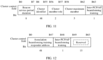
- FIG. 4 is a schematic structural diagram 1 of a channel allocation field in an EDMG extended schedule element in a beacon frame in an information transmission method according to an embodiment of this application. As shown in FIG. 4 , if a value of a scheduling type field in the channel allocation field in the EDMG extended schedule element shown in FIG.
- the channel allocation field may include a 1-bit scheduling type (Scheduling Type) field, a 24-bit allocation key field, a 2-bit channel aggregation (channel aggregation) field, an 8-bit bandwidth (BandWidth, BW) field, a 1-bit asymmetric beamforming training (Asymmetric Beamforming Training) field, a 9-bit receive direction (Receive Direction) field, a 1-bit inter-PCP/AP beamforming training or communication (Inter-PCP/AP Beamforming/communication) field, and a 3-bit reserved bit.
- the inter-PCP/AP beamforming training or communication field may be located in a reserved bit in a channel allocation field in an existing EDMG extended schedule element. If the value of the scheduling type field in the channel allocation field in the EDMG extended schedule element shown in FIG. 4 is the bit value 0, the field indicating the communication between the network devices may be located in the inter-PCP/AP beamforming training or communication field in the channel allocation field in the EDMG extended schedule element shown in FIG. 4 , namely, B44 shown in FIG. 4 .
- the device that receives the first frame sent by the first network device or obtains the first frame through listening for example, the second network device and the user equipment in the BSS in which the first network device is located, may determine that the scheduling of the first network device is used for the communication between the network devices, and the user equipment in the BSS in which the first network device is located may not participate in the scheduling of the first network device, to be specific, does not transmit information with the first network device.
- the device that receives the first frame sent by the first network device or obtains the first frame through listening may determine that the scheduling of the first network device is the common scheduling, and is not used for coordination between the network devices, to be specific, an object scheduled by the first network device is the user equipment. Therefore, the user equipment in the BSS in which the first network device is located can participate in the scheduling of the first network device and transmit information with the first network device.
- FIG. 4 merely shows a structure of the channel allocation field.
- the channel allocation field may alternatively be in another structure. Details are not described herein.
- FIG. 5 is a schematic structural diagram of an allocation key field in a channel allocation field in an EDMG extended schedule element in a beacon frame in an information transmission method according to an embodiment of this application. As shown in FIG. 5 , if the value of the scheduling type field in the channel allocation field in the EDMG extended schedule element shown in FIG. 5 , if the value of the scheduling type field in the channel allocation field in the EDMG extended schedule element shown in FIG. 5 , if the value of the scheduling type field in the channel allocation field in the EDMG extended schedule element shown in FIG.
- the allocation key field in the channel allocation field may include a 4-bit allocation identifier (Allocation ID) field, an 8-bit source association identifier (source AID) field, an 8-bit destination association identifier (Destination AID) field, a 1-bit inter-PCP/AP beamforming training or communication field, and a 3-bit reserved bit.
- the inter-PCP/AP beamforming training or communication field may be located in a reserved bit in an allocation key field in a channel allocation field in an existing EDMG extended schedule element. If the value of the scheduling type field in the channel allocation field in the EDMG extended schedule element shown in FIG. 4 is the bit value 0, the field indicating the communication between the network devices may be located in the inter-PCP/AP beamforming training or communication field in the allocation key field in the channel allocation field in the EDMG extended schedule element shown in FIG. 5 , namely, B20 shown in FIG. 5 .
- the device that receives the first frame sent by the first network device or obtains the first frame through listening may determine that the scheduling of the first network device is used for the communication between the network devices, to be specific, an object scheduled by the first network device is the network device, and the user equipment in the BSS in which the first network device is located may not participate in the scheduling of the first network device, to be specific, does not transmit information with the first network device.
- the device that receives the first frame sent by the first network device or obtains the first frame through listening may determine that the scheduling of the first network device is the common scheduling, and is not used for the communication between the network devices, to be specific, an object scheduled by the first network device is the user equipment. Therefore, the user equipment in the BSS in which the first network device is located can participate in the scheduling of the first network device and transmit information with the first network device.
- the field indicating the communication between the network devices may be further located in the source association identifier field and the destination association identifier field that are in the allocation key field in the channel allocation field in the EDMG extended schedule element shown in FIG. 5 , namely, B4-B 11 and B12-B19 that are shown in FIG. 5 .
- a value of the source association identifier field and a value of the destination association identifier field each are a value of an identifier of user equipment in a BSS in which a non-first network device is located, for example, each are 0, in other words, the value of B4-B 11 is 0 and the value of B 12-B 19 is also 0, the device that receives the first frame sent by the first network device or obtains the first frame through listening, for example, the second network device and the user equipment in the BSS in which the first network device is located, may determine that the scheduling of the first network device is used for the communication between the network devices, to be specific, each object scheduled by the first network device is the network device.
- the user equipment in the BSS in which the first network device is located may not participate in the scheduling of the first network device, to be specific, does not transmit information with the first network device.
- the value of the identifier of the user equipment in the BSS in which the non-first network device is located may alternatively be another value. Details are not described herein.
- FIG. 5 merely shows a structure of the allocation key field in the channel allocation field.
- the allocation key field in the channel allocation field may alternatively be in another structure. Details are not described herein.
- FIG. 6 is a schematic structural diagram 2 of an allocation key field in a channel allocation field in an EDMG extended schedule element in a beacon frame in an information transmission method according to an embodiment of this application. As shown in FIG. 6 , if a value of a scheduling type field in the channel allocation field in the EDMG extended schedule element shown in FIG.
- the channel allocation field in the EDMG extended schedule element may include a 1-bit scheduling type field, a 2-bit channel aggregation field, an 8-bit bandwidth field, a 1-bit asymmetric beamforming training field, a 9-bit receive direction field, a 1-bit inter-PCP/AP beamforming training or communication field, a 3-bit reserved bit, and an (8 x 15)-bit allocation field.
- the inter-PCP/AP beamforming training or communication field may be located in a reserved bit in a channel allocation field in an existing EDMG extended schedule element. If the value of the scheduling type field in the channel allocation field in the EDMG extended schedule element shown in FIG. 6 is the bit value 1, the field indicating the communication between the network devices may be located in the inter-PCP/AP beamforming training or communication field in the channel allocation field in the EDMG extended schedule element shown in FIG. 6 , namely, B20 shown in FIG. 6 .
- the device that receives the first frame sent by the first network device or obtains the first frame through listening may determine that the scheduling of the first network device is used for the communication between the network devices, to be specific, an object scheduled by the first network device is the network device, and the user equipment in the BSS in which the first network device is located may not participate in the scheduling of the first network device, to be specific, does not transmit information with the first network device.
- the device that receives the first frame sent by the first network device or obtains the first frame through listening may determine that the scheduling of the first network device is the common scheduling, and is not used for the communication between the network devices, to be specific, an object scheduled by the first network device is the user equipment. Therefore, the user equipment in the BSS in which the first network device is located can participate in the scheduling of the first network device and transmit information with the first network device.
- FIG. 6 merely shows a structure of the channel allocation field.
- the channel allocation field may alternatively be in another structure. Details are not described herein.
- FIG. 7 is a schematic structural diagram of an allocation field in an extended schedule element in a beacon frame in an information transmission method according to an embodiment of this application.
- the extended schedule element includes a 1-byte element identifier field, a 1-byte length field, and n allocation fields. Each allocation field has 15 bytes.
- Each allocation field includes a 2-byte allocation control field, a 2-byte beamforming control (BF control) field, a 1-byte source AID field, a 1-byte destination AID field, a 4-byte allocation start (allocation start) field, a 2-byte allocation block duration (allocation block duration) field, a 1-byte numbers of blocks (numbers of blocks) subfield, and a 2-byte allocation block period (allocation block period) field.
- BF control beamforming control
- allocation start allocation start
- allocation block duration allocation block duration
- allocation block period allocation block period
- the allocation control field may include a 4-bit allocation identifier (Allocation ID) field, a 3-bit allocation type (Allocation Type) field, a 1-bit pseudo-static (Pseudo-Static) field, a 1-bit truncatable (Truncatable) field, a 1-bit extendable (Extendable) field, a 1-bit personal basic service set active (PCP Active) field, a 1-bit low power single carrier used (LP SC Used) field, and a four-bit reserved bit.
- the field indicating the communication between the network devices may be located in the reserved bit in the allocation control field in the allocation field in the extended schedule element shown in FIG. 7 , namely, any bit in B12-B15 shown in FIG. 7 .
- B 12 is used as an example. If B 12 has a bit value 1, the device that receives the first frame sent by the first network device or obtains the first frame through listening, for example, the second network device and the user equipment in the BSS in which the first network device is located, may determine that the scheduling of the first network device is used for the communication between the network devices, to be specific, an object scheduled by the first network device is the network device, and the user equipment in the BSS in which the first network device is located may not participate in the scheduling of the first network device, to be specific, does not transmit information with the first network device.
- the device that receives the first frame sent by the first network device or obtains the first frame through listening may determine that the scheduling of the first network device is the common scheduling, and is not used for the communication between the network devices, to be specific, an object scheduled by the first network device is the user equipment. Therefore, the user equipment in the BSS in which the first network device is located can participate in the scheduling of the first network device and transmit information with the first network device.
- the field indicating the communication between the network devices may be further located in the allocation type field, namely, B4-B6, in the allocation control field in the allocation field shown in FIG. 7 .
- the device that receives the first frame sent by the first network device or obtains the first frame through listening may determine that the scheduling of the first network device is used for SP allocation.
- the SP allocation may be used for a non-contention-based network device and non-contention-based user equipment, or non-contention-based user equipments.
- Objects scheduled by the first network device are the user equipments, or the user equipment and the network device.
- the device that receives the first frame sent by the first network device or obtains the first frame through listening may determine that the scheduling of the first network device is used for CBAP allocation.
- the CBAP allocation may be used for a contention-based network device and contention-based user equipment, or contention-based user equipments.
- Objects scheduled by the first network device are the user equipments, or the user equipment and the network device.
- B4-B6 is a "value indicating the communication between the network devices", for example, 010, where 010 is the "value indicating the communication between the network devices" agreed on by each network element in a communications system
- the device that receives the first frame sent by the first network device or obtains the first frame through listening, for example, the second network device and the user equipment in the BSS in which the first network device is located may determine that the scheduling of the first network device is used for the communication between the network devices, to be specific, each object scheduled by the first network device is the network device. Therefore, the user equipment in the BSS in which the first network device is located may not participate in the scheduling of the first network device, to be specific, does not transmit information with the first network device.
- the foregoing "value indicating the communication between the network devices" may also be replaced with 000, 011, 101, 110, or 111.
- FIG. 7 merely shows a structure of the allocation control field in the allocation field.
- the allocation control subfield in the allocation field may alternatively be in another structure. Details are not described herein.
- the field indicating the communication between the network devices may be further located in the source association identifier field and the destination association identifier field that are in the allocation field in the extended schedule element shown in FIG. 7 .
- a value of the source association identifier field and a value of the destination association identifier field each may be a value of an identifier of user equipment in a BSS in which a non-first network device is located, for example, each are 0, in other words, the value of the source association identifier field in FIG. 7 is 0 and the value of the destination association identifier field in FIG. 7 is also 0, the device that receives the first frame sent by the first network device or obtains the first frame through listening, for example, the second network device and the user equipment in the BSS in which the first network device is located, may determine that the scheduling of the first network device is used for the communication between the network devices, to be specific, each object scheduled by the first network device is the network device.
- the user equipment in the BSS in which the first network device is located may not participate in the scheduling of the first network device, to be specific, does not transmit information with the first network device.
- the value of the identifier of the user equipment in the BSS in which the non-first network device is located may alternatively be another value. Details are not described herein.
- the foregoing field indicating the source network device identifier and the foregoing field indicating the target network device identifier may include at least one of the following locations in the first frame:
- both the field used to indicate the source network device identifier and the field used to indicate the target network device identifier can enable a network device that obtains, through listening, a frame in which the network device is located to accurately determine two scheduling parties, so as to distinguish between other devices.
- the field used to indicate the source network device identifier and the field used to indicate the target network device identifier are described below with reference to an instance.
- the field indicating the source network device identifier and the field indicating the target network device identifier that are included in the first allocation information are located in the source association identifier field and the destination association identifier field that are in the allocation key field in the channel allocation field in the EDMG extended schedule element.
- the field indicating the source network device identifier and the field indicating the target network device identifier may be located in the source association identifier field and the destination association identifier field that are in the allocation key field in the channel allocation field in the EDMG extended schedule element shown in FIG. 5 , namely, B4-B 11 and B 12-B 19 that are shown in FIG. 5 .
- the field indicating the source network device identifier may be located in the source association identifier field, namely, B4-B 11, in the allocation key field in the channel allocation field in the EDMG extended schedule element shown in FIG. 5 .
- the field indicating the target network identifier may be located in the destination association identifier field, namely, B 12-B 19, in the allocation key field in the channel allocation field in the EDMG extended schedule element shown in FIG. 5 .
- a value of the field indicating the source network device identifier namely, the value of B4-B 11 shown in FIG. 5
- a value of the field indicating the target network device identifier namely, the value of B 12-B 19 shown in FIG. 5
- the field indicating the source network device identifier and the field indicating the target network device identifier that are included in the first allocation information are located in the source association identifier field and the destination association identifier field that are in the allocation field in the extended schedule element.
- the field indicating the source network device identifier and the field indicating the target network device identifier may be located in the source association identifier field and the destination association identifier field that are in the allocation field in the extended schedule element shown in FIG. 7 .
- the field indicating the source network device identifier may be located in the source association identifier field in the allocation field in the extended schedule element shown in FIG. 7 .
- the field indicating the target network identifier may be located in the destination association identifier field in the allocation field in the extended schedule element shown in FIG. 7 .
- a value of the field indicating the source network device identifier namely, the value of the source association identifier field shown in FIG. 7
- a value of the field indicating the target network device identifier namely, the value of the destination association identifier field shown in FIG. 7
- the foregoing source network device identifier includes at least one of the following: a media access control (Media Access Control, MAC) address of the source network device, an identifier of a BSS in which the source network device is located, an AID of the BSS in which the source network device is located, an identifier obtained by preprocessing at least one of the foregoing identifiers, and the like.
- Media Access Control Media Access Control
- the target network device identifier includes at least one of the following: a MAC address of the target network device, an identifier of a BSS in which the target network device is located, an AID of the BSS in which the target network device is located, an identifier obtained by preprocessing at least one of foregoing identifiers, and the like.
- the preprocessing may include at least one processing manner such as scrambling processing or hash processing.
- the first allocation information indicating whether the first network device supports the communication between the network devices that is included in the first frame is described below by using an example with reference to a plurality of instances.
- the first allocation information may include a field used to indicate the communication between the network devices, and a field used to indicate a source network device identifier and a field used to indicate a target network device identifier.
- the field indicating the communication between the network devices may be the allocation type field, namely, B4-B6, in the allocation control field in the allocation field in the extended schedule element shown in FIG. 7 .
- the field indicating the source network device identifier and the field indicating the target network device identifier may be the source association identifier field and the destination association identifier field that are in the allocation field in the extended schedule element shown in FIG. 7 .
- a value of the allocation type field, namely, B4-B6, in the allocation control field in the allocation field in the extended schedule element shown in FIG. 7 is a "value indicating the communication between the network devices", for example, 010, where 010 is the "value indicating the communication between the network devices" agreed on by each network element in a communications system
- the device that obtains the first frame through listening or receives the first frame for example, the second network device and the user equipment in the BSS in which the first network device is located, may determine that the scheduling of the first network device is used for the communication between the network devices, to be specific, each object scheduled by the first network device is the network device.
- a value of the source association identifier field in the allocation field in the extended schedule element shown in FIG. 7 may be an identifier of the first network device, for example, some MAC addresses of the first network device, all MAC addresses of the first network device, or an AID of a BSS in which the first network device is located, and a value of the destination association identifier field in the allocation field in the extended schedule element shown in FIG.
- the 7 may be an identifier of the second network device, for example, some MAC addresses of the second network device, all MAC addresses of the second network device, or an AID of a BSS in which the second network device is located, the device that obtains the first frame through listening or receives the first frame, for example, the second network device and the user equipment in the BSS in which the first network device is located, may determine that a source network device that performs current scheduling is the first network device, and a target network device is the second network device, to distinguish between other devices.
- the some MAC addresses of the first network device may be addresses obtained after all the MAC addresses of the first network device are processed. In this way, there is a mapping relationship between all the MAC addresses and the some MAC addresses.
- the some MAC addresses of the second network device may be addresses obtained after all the MAC addresses of the second network device are processed. In this way, there is a mapping relationship between all the MAC addresses and the some MAC addresses.
- the processing may include truncation processing, scrambling processing, or another type of processing.
- all the MAC addresses may be 48-bit MAC addresses.
- the first allocation information may include a field used to indicate the communication between the network devices, and a field used to indicate a source network device identifier and a field used to indicate a target network device identifier.
- the field indicating the communication between the network devices may include the allocation type field, namely, B4-B6, that may be located in the allocation control field in the allocation field in the extended schedule element shown in FIG. 7 , and the source association identifier field and the destination association identifier field that are in the allocation field in the extended schedule element shown in FIG. 7 .
- the field indicating the source network device identifier and the field indicating the target network device identifier may be fields in an information element other than the extended schedule element in the first frame, for example, fields in a newly added information element, a multiplexable information element, an extendable information element, or another information element.
- the device that obtains the first frame through listening or receives the first frame for example, the second network device and the user equipment in the BSS in which the first network device is located, may determine that the scheduling of the first network device is used for the communication between the network devices, to be specific, each object scheduled by the first network device is the network device.
- a value of the source association identifier field and a value of the destination association identifier field in the allocation field in the extended schedule element shown in FIG. 7 each are a value of an identifier of user equipment in a BSS in which a non-first network device is located, for example, each are 0, the device that obtains the first frame through listening or receives the first frame, for example, the second network device and the user equipment in the BSS in which the first network device is located, may further determine that the scheduling of the first network device is used for the communication between the network devices, to be specific, an object scheduled by the first network device is the network device.
- a source address included in a newly added information element, a multiplexable information element, an extendable information element, or another information element in the first frame is an identifier of the first network device, for example, all MAC addresses of the first network device or an AID of a BSS in which the first network device is located
- a target address is an identifier of the second network device, for example, all MAC addresses of the second network device or an AID of a BSS in which the second network device is located
- the device that obtains the first frame through listening or receives the first frame for example, the second network device and the user equipment in the BSS in which the first network device is located, may determine that a source network device that performs current scheduling is the first network device, and a target network device is the second network device, to distinguish between other devices.
- the first allocation information may include a field used to indicate the communication between the network devices, and a field used to indicate a source network device identifier and a field used to indicate a target network device identifier.
- the field indicating the communication between the network devices may be the allocation type field, namely, B4-B6, in the allocation control field in the allocation field in the extended schedule element shown in FIG. 7 .
- the field indicating the source network device identifier and the field indicating the target network device identifier may be included in a newly added information element, a multiplexable information element, an extendable information element, or an information element other than the extended schedule element in the first frame.
- a value of the allocation type field, namely, B4-B6, in the allocation control field in the allocation field in the extended schedule element shown in FIG. 7 is a "value indicating the communication between the network devices", for example, 010, where 010 is the "value indicating the communication between the network devices" agreed on by each network element in a communications system
- the device that obtains the first frame through listening or receives the first frame for example, the second network device and the user equipment in the BSS in which the first network device is located, may determine that the scheduling of the first network device is used for the communication between the network devices, to be specific, an object scheduled by the first network device is the network device.
- a source address included in a newly added information element, a multiplexable information element, an extendable information element, or another information element in the first frame is an identifier of the first network device, for example, all MAC addresses of the first network device or an AID of a BSS in which the first network device is located
- a target address is an identifier of the second network device, for example, all MAC addresses of the second network device or an AID of a BSS in which the second network device is located
- the device that obtains the first frame through listening or receives the first frame for example, the second network device and the user equipment in the BSS in which the first network device is located, may determine that a source network device that performs current scheduling is the first network device, and a target network device is the second network device, to distinguish between other devices.
- the first allocation information may include a field used to indicate the communication between the network devices, and a field used to indicate a source network device identifier and a field used to indicate a target network device identifier.
- the field indicating the communication between the network devices may be the source association identifier field and the destination association identifier field that are in the allocation field in the extended schedule element shown in FIG. 7 .
- the field indicating the source network device identifier and the field indicating the target network device identifier may be located in a newly added information element, a multiplexable information element, an extendable information element, or another information element in the first frame.
- a value of the source association identifier field and a value of the destination association identifier field in the allocation field in the extended schedule element shown in FIG. 7 each are a value of an identifier of user equipment in a BSS in which a non-first network device is located, for example, each are 0, the device that obtains the first frame through listening or receives the first frame, for example, the second network device and the user equipment in the BSS in which the first network device is located, may determine that the scheduling of the first network device is used for the communication between the network devices, to be specific, each object scheduled by the first network device is the network device.
- a source address included in a newly added information element, a multiplexable information element, an extendable information element, or another information element in the first frame is an identifier of the first network device, for example, all MAC addresses of the first network device or an AID of a BSS in which the first network device is located
- a target address is an identifier of the second network device, for example, all MAC addresses of the second network device or an AID of a BSS in which the second network device is located
- the device that obtains the first frame through listening or receives the first frame for example, the second network device and the user equipment in the BSS in which the first network device is located, may determine that a source network device that performs current scheduling is the first network device, and a target network device is the second network device, to distinguish between other devices.
- the first allocation information may include a field used to indicate a source network device identifier and a field used to indicate a target network device identifier.
- the field indicating the source network device identifier and the field indicating the target network device identifier are the source association identifier field and the destination association identifier field that are in the allocation field in the extended schedule element shown in FIG. 7 .
- a value of the source association identifier field in the allocation field in the extended schedule element shown in FIG. 7 may be an identifier of the first network device, for example, some MAC addresses of the first network device, all MAC addresses of the first network device, or an AID of a BSS in which the first network device is located, and a value of the destination association identifier field in the allocation field in the extended schedule element shown in FIG.
- the 7 may be an identifier of the second network device, for example, some MAC addresses of the second network device, all MAC addresses of the second network device, or an AID of a BSS in which the second network device is located, the device that obtains the first frame through listening or receives the first frame, for example, the second network device and the user equipment in the BSS in which the first network device is located, may determine that a source network device that performs current scheduling is the first network device, and a target network device is the second network device, to distinguish between other devices.
- the some MAC addresses of the first network device may be addresses obtained after all the MAC addresses of the first network device are processed. In this way, there is a mapping relationship between all the MAC addresses and the some MAC addresses.
- the some MAC addresses of the second network device may be addresses obtained after all the MAC addresses of the second network device are processed. In this way, there is a mapping relationship between all the MAC addresses and the some MAC addresses.
- the processing may include truncation processing, scrambling processing, or another type of processing.
- all the MAC addresses may be 48-bit MAC addresses.
- the AID of the BSS in which the first network device is located and the AID of the BSS in which the second network device is located may be centrally allocated based on a central controller or the like.
- each network device may select, based on an AID that is of a surrounding BSS and that is obtained through listening, an identifier different from the AID that is of the BSS and that is obtained by the network device through listening.
- first allocation information used to indicate whether the first network device supports the communication between the network devices that is included in the first frame is not limited to the foregoing five implementations.
- the foregoing description is merely an example, and is not limited in this application.
- the method may further include:
- the second network device sends a second frame to the first network device, and the second frame is used to indicate whether the second network device supports the communication between the network devices.
- the second network device may further send the second frame to the first network device, so that the first network device learns that the second network device also supports the communication between the network devices, to effectively ensure information transmission between the network devices.
- that the second frame may be used to indicate whether the second network device supports the communication between the network devices includes: The second frame includes a bit used to indicate whether the second network device supports the communication between the network devices.
- a location, in the second frame, of the bit used to indicate whether the second network device supports the communication between the network devices may be similar to or the same as the location, in the first frame, of the bit used to indicate whether the first network device supports the communication between the network devices.
- that the second frame is used to indicate whether the second network device supports the communication between the network devices may include: The second frame is used for implicit indication by using a frame type.
- the second frame is used to indicate whether the first network device supports the communication between the network devices includes:
- the second frame includes second allocation information used to indicate whether the second network device supports the communication between the network devices.
- the second allocation information may include a field used to indicate the communication between the network devices, and/or a field used to indicate a source network device identifier and a field used to indicate a target network device identifier.
- the second frame further includes a field used to indicate a start time point and a field used to indicate duration.
- the first network device and the second network device have respective BIs, to ensure communication between network devices and avoid a slot conflict, the first network device and the second network device need to perform time scheduling negotiation, so that a network device can transmit information with a peer network device based on the scheduling negotiation. Descriptions are separately provided below by using an example in two different scheduling negotiation manners.
- FIG. 8 is a flowchart of a method in which a first network device initiates scheduling in an information transmission method in this application. The method may include the following steps.
- the first network device sends a first frame, where the first frame includes a field used to indicate a start time point and a field used to indicate duration.
- the field used to indicate the start time point and the field used to indicate the duration may be used to carry a scheduling time of the first network device.
- the scheduling time of the first network device may include a time in a DTI of the first network device.
- the scheduling time of the first network device may include a part or all of the time in the DTI of the first network device. If the scheduling time of the first network device includes the part of the time in the DTI of the first network device, the scheduling time of the first network device may include a preset SP or CBAP in the DTI of the first network device.
- the first frame may be a beacon frame, an announcement frame, a management frame, or another control frame in a beacon transmission slot (Beacon Transmission Interval, BTI) of the first network device.
- BTI Beacon Transmission Interval
- a second network device listens to the first frame sent by the first network device.
- the second network device may obtain, through listening, the first frame sent by the first network device, then obtain the start time point and the duration that are included in the first frame, and learn of the scheduling time of the first network device based on the start time point and the duration that are included in the first frame.
- the second network device sends a second frame based on the first frame, where the second frame includes a field used to indicate a start time point and a field used to indicate duration.
- the field used to indicate the start time point and the field used to indicate the duration that are in the second frame may be used to carry a scheduling time of the second network device.
- the scheduling time of the second network device may be determined by the second network device based on the scheduling time of the first network device, namely, the start time point and the duration that are in the first frame. If the scheduling time of the second network device may include a part of a time in a DTI of the second network device, the scheduling time of the second network device may include a preset SP or CBAP in the DTI of the second network device.
- the second network device may determine, based on the scheduling time of the first network device and an idle time of the second network device, the scheduling time of the second network device from a time at which the scheduling time of the first network device overlaps the idle time of the second network device.
- the idle time of the second network device may include the time in the DTI of the second network device.
- the idle time of the second network device may include a part or all of the time in the DTI of the second network device.
- the second network device may set the scheduling time of the first network device to the scheduling time of the second network device, to start to exchange information with the first network device at the beginning of the scheduling time of the second network device.
- the second network device may set the DTI of the second network device to a CBAP only.
- the second network device may send the second frame in a broadcast or multicast manner, or may directionally send the second frame.
- the second frame may be a beacon frame, an announcement frame, a management frame, or another control frame of the second network device.
- the first network device listens to the second frame sent by the second network device.
- the second network device can listen to the first frame that is sent by the first network device and that includes the field used to indicate the start time point and the field used to indicate the duration, and send, based on the first frame, the second frame that includes the field used to indicate the start time point and the field used to indicate the duration, so that mutual scheduling between the first network device and the second network device is implemented.
- That the second network device transmits information with the first network device in S103 in the foregoing method may include:
- the second network device may transmit the information with the first network device in the scheduling time of the second network device.
- the frame sent by the second network device to the first network device and the frame sent by the first network device to the second network device each may be a frame transmitted in the scheduling time of the second network device.
- the first network device may trigger the second network device to allocate a scheduling time, namely, the foregoing scheduling time of the second network device, so that the first network device and the second network device can exchange information in the scheduling time of the second network device, to avoid time asynchronization between different network devices and ensure information transmission.
- a scheduling time namely, the foregoing scheduling time of the second network device
- information interference is avoided because the allocated scheduling time is dedicated to information exchange between the network devices.
- FIG. 9 is a flowchart of a method in which a second network device initiates scheduling in an information transmission method in this application. The method may further include the following steps.
- the second network device sends a second frame, where the second frame includes a field used to indicate a start time point and a field used to indicate duration.
- the field used to indicate the start time point and the field used to indicate the duration may be used to carry a scheduling time of the second network device.
- the scheduling time of the second network device may include a time in a DTI of the second network device.
- the scheduling time of the second network device may include a part or all of the time in the DTI of the second network device. If the scheduling time of the second network device includes the part of the time in the DTI of the second network device, the scheduling time of the second network device may include a preset SP or CBAP in the DTI of the second network device.
- the second frame may be a beacon frame, an announcement frame, a management frame, or another control frame in a BTI of the second network device.
- a first network device listens to the second frame sent by the second network device.
- the first network device may obtain, through listening, the second frame sent by the second network device, then obtain the start time point and the duration that are included in the second frame, and learn of the scheduling time of the second network device based on the start time point and the duration that are included in the second frame.
- the first network device sends a first frame based on the second frame, where the first frame includes a field used to indicate a start time point and a field used to indicate duration.
- the field used to indicate the start time point and the field used to indicate the duration that are in the first frame may be used to carry a scheduling time of the first network device.
- the scheduling time of the first network device may be determined by the first network device based on the scheduling time of the second network device, namely, the start time point and the duration that are in the second frame. If the scheduling time of the first network device may include a part of a time in a DTI of the first network device, the scheduling time of the first network device may include a preset SP or CBAP in the DTI of the first network device.
- the first network device may determine, based on the scheduling time of the second network device and an idle time of the first network device, the scheduling time of the first network device from a time at which the scheduling time of the second network device overlaps the idle time of the first network device.
- the idle time of the first network device may include the time in the DTI of the first network device.
- the idle time of the first network device may include a part or all of the time in the DTI of the first network device.
- the first network device may set the scheduling time of the second network device to the scheduling time of the first network device, to start to exchange information with the second network device at the beginning of the scheduling time of the first network device.
- the first network device may set the DTI of the first network device to a CBAP only.
- the first network device may send the first frame in a broadcast or multicast manner, or may directionally send the first frame.
- the first frame is a beacon frame.
- the second network device listens to the first frame sent by the first network device.
- the first network device can listen to the second frame that is sent by the second network device and that includes the field used to indicate the start time point and the field used to indicate the duration, and send, based on the second frame, the first frame that includes the field used to indicate the start time point and the field used to indicate the duration, and send, based on the second frame, the first frame that includes the field used to indicate the start time point and the field used to indicate the duration, so that mutual scheduling between the first network device and the second network device is implemented.
- That the second network device transmits information with the first network device in S 103 in the foregoing method may include:
- the second network device may transmit the information with the first network device in the scheduling time of the first network device.
- the frame sent by the second network device to the first network device and the frame sent by the first network device to the second network device each may be a frame transmitted in the scheduling time of the first network device.
- the second network device may trigger the first network device to allocate a scheduling time, namely, the foregoing scheduling time of the first network device, so that the first network device and the second network device can exchange information in the scheduling time of the first network device, to avoid time asynchronization between different network devices and ensure information transmission.
- a scheduling time namely, the foregoing scheduling time of the first network device
- the first network device and the second network device can exchange information in the scheduling time of the first network device, to avoid time asynchronization between different network devices and ensure information transmission.
- information interference is avoided because the allocated scheduling time is dedicated to information exchange between the network devices.
- FIG. 10 is a flowchart 2 of signaling interaction between APs in an information transmission method in this application.
- the neighbor AP may serve as the first network device, and send beacon frames in a plurality of sending directions in a first BTI of the neighbor AP; and the AP 1 serves as the second network device, and obtains, through listening by using an omnidirectional receive antenna, the beacon frame sent by the neighbor AP.
- the AP 1 may determine, based on capability indication information in the beacon frame, that both the neighbor AP and the AP 1 support inter-AP training or communication, the AP 1 may send beacon frames in a plurality of sending directions in a BTI of the AP 1.
- the beacon frame includes second allocation information used to indicate that the AP 1 supports coordination between APs, and a field used to indicate a start time point and a field used to indicate duration.
- the neighbor AP obtains, through listening by using an omnidirectional receive antenna, the beacon frame sent by the AP 1, learns of the field used to indicate the start time point and the field used to indicate the duration, learns that a scheduling time of the AP 1 is used for communication between the APs, and then determines a scheduling time of the neighbor AP based on the scheduling time of the AP 1 and an idle time of the neighbor AP.
- the neighbor AP may send beacon frames in a plurality of sending directions in a second BTI of the neighbor AP.
- the beacon frame may include first allocation information used to indicate that the neighbor AP supports the coordination between the APs, and a field used to indicate a start time point and a field used to indicate duration.
- the AP 1 obtains, through listening by using an omnidirectional receive antenna, the beacon frame sent by the neighbor AP, learns of the field used to indicate the start time point and the field used to indicate the duration, and then learns that the scheduling time of the neighbor AP is used for the communication between the APs.
- the scheduling time of the neighbor AP is a scheduling time determined by the neighbor AP and the AP 1 through negotiation. After learning that the scheduling time of the neighbor AP is used for the communication between the APs, the AP 1 may transmit information with the neighbor AP in the scheduling time of the neighbor AP.
- a network device may be a network device cluster, for example, a personal basic service set control point cluster (PCP/AP Clustering).
- PCP/AP Clustering personal basic service set control point cluster
- An establisher of the network device cluster also referred to as a synchronization access point (Synchronization Access Point, S-AP) may serve as a first network device and send a first frame.
- the first frame may carry a cluster parameter and cluster control information.
- the first frame is a beacon frame.
- the cluster control information may be used to indicate whether beamforming training needs to be performed between network devices in a cluster in which the first network device is located.
- the beacon frame is used as an example.
- the cluster control information may be located in a preset bit in a cluster (clustering) control field in the beacon frame.
- a structure of the cluster control field may be shown in FIG. 11.
- FIG. 11 is a schematic structural diagram 1 of a cluster control field in a beacon frame in an information transmission method in this application. As shown in FIG.
- the cluster control field may include an 8-bit beacon service period duration (Beacon SP Duration) field, a 48-bit cluster identifier (Clustering ID) field, a 2-bit cluster member role (Clustering Member Role) field, a 5-bit cluster maximum member (ClusteringMaxMem) field, and a 1-bit inter-PCP/AP beamforming training (Inter-PCP/AP Beamforming Training) field.
- Beacon SP Duration 8-bit beacon service period duration
- Clustering ID cluster identifier
- Clustering Member Role 2-bit cluster member role
- ClusteringMaxMem 5-bit cluster maximum member
- Inter-PCP/AP Beamforming Training 1-bit inter-PCP/AP beamforming training
- the inter-PCP/AP beamforming training field may be located in a reserved bit in a cluster control field in an existing beacon frame. If the value of the discovery mode field in the beacon frame is the bit value 0, the cluster control information may be located in the inter-PCP/AP beamforming training field in the cluster control field in the beacon frame shown in FIG. 11 , namely, B63 shown in FIG. 11 .
- B63 has a bit value 1
- a device that obtains the beacon frame through listening for example, the second network device or another network device, may determine that beamforming training needs to be performed between the network devices in a cluster in which the first network device is located.
- B63 has a bit value 1
- a device that obtains the beacon frame through listening for example, the second network device or another network device, may determine that beamforming training does not need to be performed between the network devices in a cluster in which the first network device is located.
- FIG. 12 is a schematic structural diagram 2 of a cluster control field in a beacon frame in an information transmission method in this application.
- the cluster control field may include a 48-bit association beamforming training responder address (A-BFT Responder Address) field, a 1-bit inter-PCP/AP beamforming training field, and a 15-bit reserved bit.
- the inter-PCP/AP beamforming training field may be located in a reserved bit in a cluster control field in an existing beacon frame. If the value of the discovery mode field in the beacon frame is the bit value 1, the cluster control information may be located in the inter-PCP/AP beamforming training field in the cluster control field in the beacon frame shown in FIG. 12 , namely, B48 shown in FIG. 12 .
- a device that obtains the beacon frame through listening may determine that beamforming training needs to be performed between the network devices in a cluster in which the first network device is located.
- a device that obtains the beacon frame through listening may determine that beamforming training does not need to be performed between the network devices in a cluster in which the first network device is located.
- the cluster control information may alternatively be located in a reserved bit in an ECAPC policy detail field (ECAPC Policy Detail Field) in an ECAPC policy element (ECAPC Policy Element) in the beacon frame.
- FIG. 13 is a schematic structural diagram of an ECAPC policy detail field in an ECAPC policy element in a beacon frame in an information transmission method in this application. As shown in FIG.
- the ECAPC policy element may include a 1-byte element identifier (Element ID) field, a 1-byte length (length) field, a 1-byte ECAPC policy detail field, a 6-byte centralized coordination service root identifier (Centralized Coordination service Root ID, CCSR ID) field, a 4-byte available cluster time offset bitmap (Available Cluster Time Offset Bitmap) field, a 0-byte or 2-byte TXSS contention based access period offset (TXSS CBAP Offset) field, a 0-byte or 1-byte TXSS contention based access period duration (TXSS CBAP Duration) field, and a 0-byte or 1-byte TXSS contention based access period maximum member (TXSS CBAP MaxMem) field.
- element ID element identifier
- length length
- ECAPC policy detail field a 6-byte centralized coordination service root identifier
- CCSR ID Centralized Coordination service Root ID
- 4-byte available cluster time offset bitmap Available Cluster Time Offset Bitmap
- the TXSS contention based access period offset field, the TXSS contention based access period duration field, and the TXSS contention based access period maximum member field may be optional fields in the ECAPC policy element.
- the ECAPC policy detail field may include a 1-bit beacon header slot enforced (BHI Enforced) field, a 1-bit TXSS contention based access period enforced (TXSS CBAP Enforced) field, a 1-bit protected period enforced (Protected Period Enforced) field, a 1-bit inter-PCP/AP beamforming training (inter-PCP/AP beamforming training) enforced field, and a 4-bit reserved field.
- BHI Enforced beacon header slot enforced
- TXSS CBAP Enforced TXSS contention based access period enforced
- Protected Period Enforced Protected Period Enforced
- inter-PCP/AP beamforming training inter-PCP/AP beamforming training
- the inter-PCP/AP beamforming training enforced field may be located in a reserved bit in an ECAPC policy detail field in an ECAPC policy element in an existing beacon frame.
- the cluster control information may be located in the inter-PCP/AP beamforming training enforced field in the ECAPC policy detail field in the ECAPC policy element in the beacon frame shown in FIG. 13 , namely, B3 shown in FIG. 13 .
- B3 has a bit value 1
- a device that obtains the beacon frame through listening for example, the second network device or another network device, may determine that beamforming training needs to be performed between network devices in a cluster in which the first network device is located.
- B3 has a bit value 1
- a device that obtains the beacon frame through listening for example, the second network device or another network device, may determine that beamforming training does not need to be performed between network devices in a cluster in which the first network device is located.
- FIG. 14 is a schematic structural diagram 1 of a second network device according to an embodiment of this application. As shown in FIG. 14 , the second network device 1400 may include:
- the first frame may be used to indicate whether the first network device supports the communication between the network devices includes: the first frame includes a bit used to indicate whether the first network device supports the communication between the network devices.
- the first frame is used to indicate whether the first network device supports the communication between the network devices includes: the first frame is used for implicit indication by using a frame type.
- the first frame is used to indicate whether the first network device supports the communication between the network devices includes: the first frame includes first allocation information used to indicate whether the first network device supports the communication between the network devices.
- the first allocation information includes a field used to indicate the communication between the network devices, and/or a field used to indicate a source network device identifier and a field used to indicate a target network device identifier.
- the field indicating the communication between the network devices includes at least one of the following locations in the first frame:
- the field indicating the source network device identifier and the field indicating the target network device identifier include at least one of the following locations in the first frame:
- the field indicating the communication between the network devices includes an allocation type field in an allocation control field in an allocation field in an extended schedule element in the first frame; and the field indicating the source network device identifier and the field indicating the target network device identifier are a source association identifier field and a destination association identifier field that are in the allocation field in the extended schedule element in the first frame.
- the field indicating the communication between the network devices includes an allocation type field in an allocation control field in an allocation field in an extended schedule element in the first frame, and a source association identifier field and a destination association identifier field that are in the allocation field; and the field indicating the source network device identifier and the field indicating the target network device identifier are fields in an information element other than the extended schedule element in the first frame.
- the field indicating the communication between the network devices includes an allocation type field in an allocation control field in an allocation field in an extended schedule element in the first frame; and the field indicating the source network device identifier and the field indicating the target network device identifier are fields in an information element other than the extended schedule element in the first frame.
- the field indicating the communication between the network devices includes a source association identifier field and a destination association identifier field that are in an allocation field in an extended schedule element in the first frame; and the field indicating the source network device identifier and the field indicating the target network device identifier are fields in an information element other than the extended schedule element in the first frame.
- the field indicating the source network device identifier and the field indicating the target network device identifier are a source association identifier field and a destination association identifier field that are in an allocation field in an extended schedule element in the first frame.
- the first frame further includes a field used to indicate a start time point and a field used to indicate duration.
- the processing module 1401 is further configured to control to send a second frame to the first network device, where the second frame indicates whether the second network device supports the communication between the network devices; and the transceiver module 1402 is configured to send the second frame to the first network device.
- the second frame is used to indicate whether the second network device supports the communication between the network devices includes: the second frame includes a bit used to indicate whether the second network device supports the communication between the network devices.
- the second frame is used to indicate whether the second network device supports the communication between the network devices includes: the second frame is used for implicit indication by using a frame type.
- the second frame is used to indicate whether the first network device supports the communication between the network devices includes: the second frame includes second allocation information used to indicate whether the second network device supports the communication between the network devices.
- the second allocation information includes a field used to indicate the communication between the network devices, and/or a field used to indicate a source network device identifier and a field used to indicate a target network device identifier.
- the field indicating the communication between the network devices includes at least one of the following locations in the second frame:
- the field indicating the source network device identifier and the field indicating the target network device identifier include at least one of the following locations in the second frame:
- the field indicating the communication between the network devices includes an allocation type field in an allocation control field in an allocation field in an extended schedule element in the second frame; and the field indicating the source network device identifier and the field indicating the target network device identifier are a source association identifier field and a destination association identifier field that are in the allocation field in the extended schedule element in the second frame.
- the field indicating the communication between the network devices includes an allocation type field in an allocation control field in an allocation field in an extended schedule element in the second frame, and a source association identifier field and a destination association identifier field that are in the allocation field; and the field indicating the source network device identifier and the field indicating the target network device identifier are fields in an information element other than the extended schedule element in the second frame.
- the field indicating the communication between the network devices includes an allocation type field in an allocation control field in an allocation field in an extended schedule element in the second frame; and the field indicating the source network device identifier and the field indicating the target network device identifier are fields in an information element other than the extended schedule element in the second frame.
- the field indicating the communication between the network devices includes a source association identifier field and a destination association identifier field that are in an allocation field in an extended schedule element in the second frame; and the field indicating the source network device identifier and the field indicating the target network device identifier are fields in an information element other than the extended schedule element in the second frame.
- the field indicating the source network device identifier and the field indicating the target network device identifier are a source association identifier field and a destination association identifier field that are in an allocation field in an extended schedule element in the second frame.
- the second frame further includes a field used to indicate a start time point and a field used to indicate duration.
- the processing module 1401 is configured to: in an A-BFT period, control to send a sweep frame to the first network device, and control to receive a sweep feedback frame sent by the first network device; and the transceiver module 1402 is configured to: send the sweep frame to the first network device, and receive the sweep feedback frame sent by the first network device.
- the processing module 1401 is configured to: in an ATI, control to receive a request frame sent by the first network device, and control to send a response frame to the first network device; and the transceiver module 1402 is configured to: receive the request frame sent by the first network device, and send the response frame to the first network device.
- the processing module 1401 is configured to: in a preset time period in a DTI, control to send a data frame, a control frame, or a management frame to the first network device, and control to receive a data frame, a control frame, or a management frame sent by the first network device; and the transceiver module 1402 is configured to: send the data frame, the control frame, or the management frame to the first network device, and receive the data frame, the control frame, or the management frame sent by the first network device.
- FIG. 15 is a schematic structural diagram 2 of a second network device according to an embodiment of this application.
- the second network device in FIG. 14 may be implemented in a plurality of product forms.
- the second network device may be implemented by using a bus 1501 as a general bus architecture.
- the bus 1501 may include any quantity of interconnect buses and bridges based on a specific application and an overall design constraint of the second network device.
- the bus 1501 connects various circuits together. These circuits include a processor 1502, a storage medium 1503, a bus interface 1504, and a user interface 1506.
- the second network device uses the bus interface 1504 to connect a network adapter 1505 and the like by using the bus 1501.
- the network adapter 1505 may be configured to: implement a signal processing function at a physical layer in a wireless local area network, and send and receive a radio frequency signal by using an antenna 1507.
- the antenna 1507 is configured to implement information receiving and sending performed by the second network device in the foregoing method embodiments.
- the user interface 1506 may be connected to a user terminal such as a keyboard, a display, a mouse, or a joystick.
- the bus 1501 may be further connected to various other circuits such as a timing source, a peripheral device, a voltage regulator, and a power management circuit. These circuits are well-known in the art, and therefore are not described in detail.
- the processor 1502 is responsible for bus management and general processing (including executing software stored in the storage medium 1503).
- the processor 1502 may be implemented by using one or more general purpose processors and/or dedicated processors.
- the processor includes a microprocessor, a microcontroller, a DSP processor, and another circuit that can execute software.
- the software should be broadly construed as representation of an instruction, data, or any combination thereof, regardless of whether the software is referred to as software, firmware, middleware, microcode, a hardware description language, or the like.
- the processor 1502 is configured to implement all processing except information receiving and sending performed by the second network device in the foregoing method embodiments.
- the storage medium 1503 is separated from the processor 1502.
- the storage medium 1503 or any part of the storage medium 1503 may be located outside the second network device.
- the storage medium 1503 may include a transmission line, a carrier waveform modulated by using data, and/or a computer product separated from a wireless node. These media may be accessed by the processor 1502 by using the bus interface 1504.
- the storage medium 1503 or any part of the storage medium 1503 may be integrated into the processor 1502.
- the storage medium 1503 may be a cache and/or a general-purpose register.
- the storage medium 1803 is configured to store a computer program, and the computer program is executed by the processor 1502, to implement all processing performed by the processor 1502.
- the second network device may be configured as a general-purpose processing system, for example, collectively referred to as a chip.
- the general-purpose processing system includes one or more microprocessors providing a processor function, and an external memory providing at least a part of the storage medium 1503. All of these are connected to another support circuit by using an external bus architecture.
- the second network device may be implemented by using the following: an application-specific integrated circuit (application-specific integrated circuit, ASIC) having the processor 1502, the bus interface 1504, and the user interface 1506, and at least a part of the storage medium 1503 integrated into a single chip.
- ASIC application-specific integrated circuit
- the second network device may be implemented by using the following: one or more field-programmable gate arrays (field-programmable gate array, FPGA), a programmable logic device (programmable logic device, PLD), a controller, a state machine, gate logic, a discrete hardware component, any other suitable circuit, or any combination of circuits that can perform various functions described in this application.
- field-programmable gate array FPGA
- programmable logic device programmable logic device
- PLD programmable logic device
- controller a state machine, gate logic, a discrete hardware component, any other suitable circuit, or any combination of circuits that can perform various functions described in this application.
- the second network device in FIG. 14 and FIG. 15 has any function of the second network device in the foregoing method embodiments. Details are not described herein again.
- an embodiment of this application further provides a computer readable storage medium.
- the computer readable storage medium may include an instruction.
- the instruction When the instruction is run on a computer, the computer is enabled to perform the information transmission method performed by the second network device shown in any one of the foregoing embodiments.
- an embodiment of this application further provides a computer program product including an instruction.
- the computer program product When the computer program product is run on a computer, the computer is enabled to perform the information transmission method performed by the second network device shown in any one of the foregoing embodiments.
- Functions of the computer program product may be implemented by using hardware or software.
- the functions When the functions are implemented by using software, the functions may be stored in a computer readable medium or transmitted as one or more instructions or code in the computer readable storage medium.
- the second network device, the computer readable storage medium, and the computer program product in the embodiments of this application may perform the information transmission method performed by the second network device shown in any one of the foregoing descriptions.
- the second network device may perform the information transmission method performed by the second network device shown in any one of the foregoing descriptions.
- FIG. 16 is a schematic structural diagram 1 of a first network device according to an embodiment of this application. As shown in FIG. 16 , the first network device 1600 may include:
- that the first frame is used to indicate whether the first network device supports the communication between the network devices includes: the first frame includes a bit used to indicate whether the first network device supports the communication between the network devices.
- the first frame is used to indicate whether the first network device supports the communication between the network devices includes: the first frame is used for implicit indication by using a frame type.
- that the first frame is used to indicate whether the first network device supports the communication between the network devices includes: the first frame includes first allocation information used to indicate whether the first network device supports the communication between the network devices.
- the first allocation information includes a field used to indicate the communication between the network devices, and/or a field used to indicate a source network device identifier and a field used to indicate a target network device identifier.
- the field indicating the communication between the network devices includes at least one of the following locations in the first frame:
- the field indicating the source network device identifier and the field indicating the target network device identifier include at least one of the following locations in the first frame:
- the field indicating the communication between the network devices includes an allocation type field in an allocation control field in an allocation field in an extended schedule element in the first frame; and the field indicating the source network device identifier and the field indicating the target network device identifier are a source association identifier field and a destination association identifier field that are in the allocation field in the extended schedule element in the first frame.
- the field indicating the communication between the network devices includes an allocation type field in an allocation control field in an allocation field in an extended schedule element in the first frame, and a source association identifier field and a destination association identifier field that are in the allocation field; and the field indicating the source network device identifier and the field indicating the target network device identifier are fields in an information element other than the extended schedule element in the first frame.
- the field indicating the communication between the network devices includes an allocation type field in an allocation control field in an allocation field in an extended schedule element in the first frame; and the field indicating the source network device identifier and the field indicating the target network device identifier are fields in an information element other than the extended schedule element in the first frame.
- the field indicating the communication between the network devices includes a source association identifier field and a destination association identifier field that are in an allocation field in an extended schedule element in the first frame; and the field indicating the source network device identifier and the field indicating the target network device identifier are fields in an information element other than the extended schedule element in the first frame.
- the field indicating the source network device identifier and the field indicating the target network device identifier are a source association identifier field and a destination association identifier field that are in an allocation field in an extended schedule element in the first frame.
- the first frame further includes a field used to indicate a start time point and a field used to indicate duration.
- the processing module 1601 is further configured to: before controlling to transmit the information with the second network device, control to receive a second frame sent by the second network device, where the second frame indicates whether the second network device supports the communication between the network devices; and the transceiver module 1602 is further configured to receive the second frame sent by the second network device.
- that the second frame is used to indicate whether the second network device supports the communication between the network devices includes: the second frame includes a bit used to indicate whether the second network device supports the communication between the network devices.
- the second frame is used to indicate whether the second network device supports the communication between the network devices includes: the second frame is used for implicit indication by using a frame type.
- that the second frame is used to indicate whether the second network device supports the communication between the network devices includes: the second frame includes second allocation information used to indicate whether the second network device supports the communication between the network devices.
- the second allocation information includes a field used to indicate the communication between the network devices, and/or a field used to indicate a source network device identifier and a field used to indicate a target network device identifier.
- the field indicating the communication between the network devices includes at least one of the following locations in the second frame:
- the field indicating the source network device identifier and the field indicating the target network device identifier include at least one of the following locations in the second frame:
- the field indicating the communication between the network devices includes an allocation type field in an allocation control field in an allocation field in an extended schedule element in the second frame; and the field indicating the source network device identifier and the field indicating the target network device identifier are a source association identifier field and a destination association identifier field that are in the allocation field in the extended schedule element in the second frame.
- the field indicating the communication between the network devices includes an allocation type field in an allocation control field in an allocation field in an extended schedule element in the second frame, and a source association identifier field and a destination association identifier field that are in the allocation field; and the field indicating the source network device identifier and the field indicating the target network device identifier are fields in an information element other than the extended schedule element in the second frame.
- the field indicating the communication between the network devices includes an allocation type field in an allocation control field in an allocation field in an extended schedule element in the second frame; and the field indicating the source network device identifier and the field indicating the target network device identifier are fields in an information element other than the extended schedule element in the second frame.
- the field indicating the communication between the network devices includes a source association identifier field and a destination association identifier field that are in an allocation field in an extended schedule element in the second frame; and the field indicating the source network device identifier and the field indicating the target network device identifier are fields in an information element other than the extended schedule element in the second frame.
- the field indicating the source network device identifier and the field indicating the target network device identifier are a source association identifier field and a destination association identifier field that are in an allocation field in an extended schedule element in the second frame.
- the second frame may further include a field used to indicate a start time point and a field used to indicate duration.
- the processing module 1601 is configured to: in an A-BFT period, control to receive a sweep frame sent by the second network device, and control to send a sweep feedback frame to the second network device; and the transceiver module 1602 is configured to: receive the sweep frame sent by the second network device, and send the sweep feedback frame to the second network device.
- the processing module 1601 is configured to: in an ATI, control to send a request frame to the second network device, and control to receive a response frame sent by the second network device; and the transceiver module 1602 is configured to: send the request frame to the second network device, and receive the response frame sent by the second network device.
- the processing module 1601 is configured to: in a preset time period in a DTI, control to receive a data frame, a control frame, or a management frame sent by the second network device, and control to send a data frame, a control frame, or a management frame to the second network device; and the transceiver module 1602 is configured to: receive the data frame, the control frame, or the management frame sent by the second network device, and send the data frame, the control frame, or the management frame to the second network device.
- FIG. 17 is a schematic structural diagram 2 of a first network device according to an embodiment of this application.
- the first network device in FIG. 16 may be implemented in a plurality of product forms.
- the first network device may be implemented by using a bus 1701 as a general bus architecture.
- the bus 1701 may include any quantity of interconnect buses and bridges based on a specific application and an overall design constraint of the first network device.
- the bus 1701 connects various circuits together. These circuits include a processor 1702, a storage medium 1703, a bus interface 1704, and a user interface 1706.
- the first network device uses the bus interface 1704 to connect a network adapter 1705 and the like by using the bus 1701.
- the network adapter 1705 may be configured to: implement a signal processing function at a physical layer in a wireless local area network, and send and receive a radio frequency signal by using an antenna 1707.
- the antenna 1707 is configured to implement information receiving and sending performed by the first network device in the foregoing method embodiments.
- the user interface 1706 may be connected to a user terminal such as a keyboard, a display, a mouse, or a joystick.
- the bus 1701 may be further connected to various other circuits such as a timing source, a peripheral device, a voltage regulator, and a power management circuit. These circuits are well-known in the art, and therefore are not described in detail.
- the processor 1702 is responsible for bus management and general processing (including executing software stored in the storage medium 1703).
- the processor 1702 may be implemented by using one or more general purpose processors and/or dedicated processors.
- the processor includes a microprocessor, a microcontroller, a DSP processor, and another circuit that can execute software.
- the software should be broadly construed as representation of an instruction, data, or any combination thereof, regardless of whether the software is referred to as software, firmware, middleware, microcode, a hardware description language, or the like.
- the processor 1702 is configured to implement all processing except information receiving and sending performed by the first network device in the foregoing method embodiments.
- the storage medium 1703 is separated from the processor 1702.
- the storage medium 1703 or any part of the storage medium 1703 may be located outside the first network device.
- the storage medium 1703 may include a transmission line, a carrier waveform modulated by using data, and/or a computer product separated from a wireless node. These media may be accessed by the processor 1702 by using the bus interface 1704.
- the storage medium 1703 or any part of the storage medium 1703 may be integrated into the processor 1702.
- the storage medium 1703 may be a cache and/or a general-purpose register.
- the storage medium 1703 is configured to store a computer program, and the computer program is executed by the processor 1702, to implement all processing performed by the processor 1702.
- the first network device may be configured as a general-purpose processing system, for example, collectively referred to as a chip.
- the general-purpose processing system includes one or more microprocessors providing a processor function, and an external memory providing at least a part of the storage medium 1703. All of these are connected to another support circuit by using an external bus architecture.
- the first network device may be implemented by using the following: an ASIC having the processor 1702, the bus interface 1704, and the user interface 1706, and at least a part of the storage medium 1703 integrated into a single chip.
- the first network device may be implemented by using the following: one or more FPGAs, a PLD, a controller, a state machine, gate logic, a discrete hardware component, any other suitable circuit, or any combination of circuits that can perform various functions described in this application.
- the first network device in FIG. 16 and FIG. 17 has any function of the first network device in the foregoing method embodiments. Details are not described herein again.
- an embodiment of this application further provides a computer readable storage medium.
- the computer readable storage medium may include an instruction.
- the instruction When the instruction is run on a computer, the computer is enabled to perform the information transmission method performed by the first network device shown in any one of the foregoing embodiments.
- an embodiment of this application further provides a computer program product including an instruction.
- the computer program product When the computer program product is run on a computer, the computer is enabled to perform the information transmission method performed by the first network device shown in any one of the foregoing embodiments.
- Functions of the computer program product may be implemented by using hardware or software.
- the functions When the functions are implemented by using software, the functions may be stored in a computer readable medium or transmitted as one or more instructions or code in the computer readable storage medium.
- the first network device, the computer readable storage medium, and the computer program product in the embodiments of this application may perform the information transmission method performed by the first network device shown in any one of the foregoing descriptions.
- the first network device, the computer readable storage medium, and the computer program product in the embodiments of this application may perform the information transmission method performed by the first network device shown in any one of the foregoing descriptions.
- the embodiments may be implemented by using software, hardware, firmware, or any combination thereof.
- the embodiments may be implemented completely or partially in a form of a computer program product.
- the computer program product includes one or more computer instructions.
- the computer may be a general-purpose computer, a dedicated computer, a computer network, or another programmable apparatus.
- the computer instructions are stored in a computer readable storage medium, or transmitted from a computer readable storage medium to another computer readable storage medium.
- the computer instructions may be transmitted from a website, computer, server, or data center to another website, computer, server, or data center in a wired (for example, a coaxial cable, an optical fiber, or a digital subscriber line (DSL)) or wireless (for example, infrared, radio, or microwave) manner.
- the computer readable storage medium may be any usable medium accessible by a computer, or a data storage device, such as a server or a data center, integrating one or more usable media.
- the usable medium may be a magnetic medium (for example, a floppy disk, a hard disk, or a magnetic tape), an optical medium (for example, a DVD), a semiconductor medium (for example, a solid state disk solid state disk (SSD)), or the like.
- a magnetic medium for example, a floppy disk, a hard disk, or a magnetic tape
- an optical medium for example, a DVD
- a semiconductor medium for example, a solid state disk solid state disk (SSD)
Landscapes
- Engineering & Computer Science (AREA)
- Signal Processing (AREA)
- Computer Networks & Wireless Communication (AREA)
- Computer Security & Cryptography (AREA)
- Databases & Information Systems (AREA)
- Mobile Radio Communication Systems (AREA)
- Data Exchanges In Wide-Area Networks (AREA)
Claims (12)
- Second dispositif de réseau (1400), comprenant un module de traitement (1401) et un module émetteur-récepteur (1402), dans lequel le module de traitement (1401) est connecté au module émetteur-récepteur (1402) ;le module émetteur-récepteur (1401) est configuré pour écouter une première trame, dans lequel la première trame est utilisée pour indiquer si un premier dispositif de réseau prend en charge la communication entre des dispositifs de réseau ; etle module de traitement (1402) est configuré pour contrôler la transmission d'informations avec le premier dispositif de réseau si le premier dispositif de réseau et le second dispositif de réseau tous deux prennent en charge la communication entre les dispositifs de réseau ;dans lequel le fait que la première trame soit utilisée pour indiquer si le premier dispositif de réseau prend en charge la communication entre des dispositifs de réseau comprend le fait que : la première trame comprend des premières informations d'allocation utilisées pour indiquer si le premier dispositif de réseau prend en charge la communication entre les dispositifs de réseau,dans lequel les premières informations d'allocation comprennent un champ indiquant la communication entre les dispositifs de réseau, et/ou un champ indiquant un identifiant de dispositif de réseau source et un champ indiquant un identifiant de dispositif de réseau cible, etcaractérisé en ce quele champ indiquant la communication entre les dispositifs de réseau comprend un champ d'identifiant d'association source et un champ d'identifiant d'association de destination qui se trouvent dans un champ d'allocation dans un élément de programme étendu, ou un champ d'identifiant d'association source et un champ d'identifiant d'association de destination qui se trouvent dans un champ de clé d'allocation dans un champ d'allocation de canal dans un élément de programme étendu multi-gigabit directionnel amélioré EDMG ;le module de traitement (1402) est en outre configuré pour déterminer que la programmation du premier dispositif de réseau est utilisée pour la communication entre des dispositifs de réseau, si une valeur du champ d'identifiant d'association source et une valeur du champ d'identifiant d'association de destination sont chacune 0.
- Second dispositif de réseau (1400) selon la revendication 1, dans lequel le champ indiquant la communication entre les dispositifs de réseau comprend au moins l'un des emplacements suivants dans la première trame :un bit réservé dans un champ de contrôle d'allocation dans le champ d'allocation dans l'élément de programme étendu ;un champ de type d'allocation dans le champ de contrôle d'allocation dans le champ d'allocation dans l'élément de programme étendu ;un bit réservé dans le champ d'allocation de canal dans l'élément de programme étendu EDMG ; etun bit réservé dans le champ de clé d'allocation dans le champ d'allocation de canal dans l'élément de programme étendu EDMG.
- Second dispositif de réseau (1400) selon la revendication 1, dans lequel le champ indiquant l'identifiant de dispositif de réseau source et le champ indiquant l'identifiant de dispositif de réseau cible comprennent au moins l'un des emplacements suivants dans la première trame :un champ d'identifiant d'association source et un champ d'identifiant d'association de destination qui se trouvent dans un champ d'allocation dans un élément de programme étendu ;des champs dans un élément d'information autre que l'élément de programme étendu dans la première trame ;un champ d'identifiant d'association source et un champ d'identifiant d'association de destination qui se trouvent dans un champ de clé d'allocation dans un champ d'allocation de canal dans un élément de programme étendu EDMG ; etdes champs dans un élément d'information autre que l'élément de programme étendu EDMG dans la première trame.
- Second dispositif de réseau (1400) selon la revendication 1, dans lequel le champ indiquant la communication entre les dispositifs de réseau comporte un champ de type d'allocation dans un champ de contrôle d'allocation dans un champ d'allocation dans un élément de programme étendu dans la première trame ; et le champ indiquant l'identifiant de dispositif de réseau source et le champ indiquant l'identifiant de dispositif de réseau cible sont un champ d'identifiant d'association source et un champ d'identifiant d'association de destination qui se trouvent dans le champ d'allocation dans l'élément de programme étendu dans la première trame ; oule champ indiquant la communication entre les dispositifs de réseau comprend un champ de type d'allocation dans un champ de contrôle d'allocation dans un champ d'allocation dans un élément de programme étendu dans la première trame, et un champ d'identifiant d'association source et un champ d'identifiant d'association de destination qui se trouvent dans le champ d'allocation ; et le champ indiquant l'identifiant de dispositif de réseau source et le champ indiquant l'identifiant de dispositif de réseau cible sont des champs dans un élément d'information autre que l'élément de programme étendu dans la première trame ; oule champ indiquant la communication entre les dispositifs de réseau comporte un champ de type d'allocation dans un champ de contrôle d'allocation dans un champ d'allocation dans un élément de programme étendu dans la première trame ; et le champ indiquant l'identifiant de dispositif de réseau source et le champ indiquant l'identifiant de dispositif de réseau cible sont des champs dans un élément d'information autre que l'élément de programme étendu dans la première trame ; oule champ indiquant la communication entre les dispositifs de réseau comporte un champ d'identifiant d'association source et un champ d'identifiant d'association de destination qui se trouvent dans un champ d'allocation dans un élément de programme étendu dans la première trame ; et le champ indiquant l'identifiant de dispositif de réseau source et le champ indiquant l'identifiant de dispositif de réseau cible sont des champs dans un élément d'information autre que l'élément de programme étendu dans la première trame ; oule champ indiquant l'identifiant de dispositif de réseau source et le champ indiquant l'identifiant de dispositif de réseau cible sont un champ d'identifiant d'association source et un champ d'identifiant d'association de destination qui se trouvent dans un champ d'allocation dans un élément de programme étendu dans la première trame.
- Premier dispositif de réseau (1600), comprenant un module de traitement (1601) et un module émetteur-récepteur (1602), dans lequel le module de traitement (1601) est connecté au module émetteur-récepteur (1602) ;le module émetteur-récepteur (1602) est configuré pour envoyer une première trame, dans lequel la première trame est utilisée pour indiquer si le premier dispositif de réseau prend en charge la communication entre des dispositifs de réseau ; etle module de traitement (1601) est configuré pour contrôler la transmission d'informations avec un second dispositif de réseau si le premier dispositif de réseau et le second dispositif de réseau tous deux prennent en charge la communication entre les dispositifs de réseau ;dans lequel le fait que la première trame soit utilisée pour indiquer si le premier dispositif de réseau prend en charge la communication entre des dispositifs de réseau comprend le fait que : la première trame comprend des premières informations d'allocation utilisées pour indiquer si le premier dispositif de réseau prend en charge la communication entre les dispositifs de réseau,dans lequel les premières informations d'allocation comprennent un champ indiquant la communication entre les dispositifs de réseau, et/ou un champ indiquant un identifiant de dispositif de réseau source et un champ indiquant un identifiant de dispositif de réseau cible,caractérisé en ce quele champ indiquant la communication entre les dispositifs de réseau comprend un champ d'identifiant d'association source et un champ d'identifiant d'association de destination qui se trouvent dans un champ d'allocation dans un élément de programme étendu, ou un champ d'identifiant d'association source et un champ d'identifiant d'association de destination qui se trouvent dans un champ de clé d'allocation dans un champ d'allocation de canal dans un élément de programme étendu multi-gigabit directionnel amélioré EDMG ; etdans lequel si la programmation du premier dispositif de réseau est utilisée pour la communication entre des dispositifs de réseau, une valeur du champ d'identifiant d'association source et une valeur du champ d'identifiant d'association de destination sont chacune 0.
- Premier dispositif de réseau (1600) selon la revendication 5, dans lequel le champ indiquant la communication entre les dispositifs de réseau comprend au moins l'un des emplacements suivants dans la première trame :un bit réservé dans un champ de contrôle d'allocation dans le champ d'allocation dans l'élément de programme étendu ;un champ de type d'allocation dans le champ de contrôle d'allocation dans le champ d'allocation dans l'élément de programme étendu ;un bit réservé dans le champ d'allocation de canal dans l'élément de programme étendu EDMG ; etun bit réservé dans le champ de clé d'allocation dans le champ d'allocation de canal dans l'élément de programme étendu EDMG.
- Premier dispositif de réseau (1600) selon la revendication 5, dans lequel le champ indiquant l'identifiant de dispositif de réseau source et le champ indiquant l'identifiant de dispositif de réseau cible comprennent au moins l'un des emplacements suivants dans la première trame :un champ d'identifiant d'association source et un champ d'identifiant d'association de destination qui se trouvent dans un champ d'allocation dans un élément de programme étendu ;des champs dans un élément d'information autre que l'élément de programme étendu dans la première trame ;un champ d'identifiant d'association source et un champ d'identifiant d'association de destination qui se trouvent dans un champ de clé d'allocation dans un champ d'allocation de canal dans un élément de programme étendu EDMG ; etdes champs dans un élément d'information autre que l'élément de programme étendu EDMG dans la première trame.
- Premier dispositif de réseau (1600) selon la revendication 5, dans lequel le champ indiquant la communication entre les dispositifs de réseau comporte un champ de type d'allocation dans un champ de contrôle d'allocation dans un champ d'allocation dans un élément de programme étendu dans la première trame ; et le champ indiquant l'identifiant de dispositif de réseau source et le champ indiquant l'identifiant de dispositif de réseau cible sont un champ d'identifiant d'association source et un champ d'identifiant d'association de destination qui se trouvent dans le champ d'allocation dans l'élément de programme étendu dans la première trame ; oule champ indiquant la communication entre les dispositifs de réseau comprend un champ de type d'allocation dans un champ de contrôle d'allocation dans un champ d'allocation dans un élément de programme étendu dans la première trame, et un champ d'identifiant d'association source et un champ d'identifiant d'association de destination qui se trouvent dans le champ d'allocation ; et le champ indiquant l'identifiant de dispositif de réseau source et le champ indiquant l'identifiant de dispositif de réseau cible sont des champs dans un élément d'information autre que l'élément de programme étendu dans la première trame ; oule champ indiquant la communication entre les dispositifs de réseau comporte un champ de type d'allocation dans un champ de contrôle d'allocation dans un champ d'allocation dans un élément de programme étendu dans la première trame ; et le champ indiquant l'identifiant de dispositif de réseau source et le champ indiquant l'identifiant de dispositif de réseau cible sont des champs dans un élément d'information autre que l'élément de programme étendu dans la première trame ; oule champ indiquant la communication entre les dispositifs de réseau comporte un champ d'identifiant d'association source et un champ d'identifiant d'association de destination qui se trouvent dans un champ d'allocation dans un élément de programme étendu dans la première trame ; et le champ indiquant l'identifiant de dispositif de réseau source et le champ indiquant l'identifiant de dispositif de réseau cible sont des champs dans un élément d'information autre que l'élément de programme étendu dans la première trame ; oule champ indiquant l'identifiant de dispositif de réseau source et le champ indiquant l'identifiant de dispositif de réseau cible sont un champ d'identifiant d'association source et un champ d'identifiant d'association de destination qui se trouvent dans un champ d'allocation dans un élément de programme étendu dans la première trame.
- Procédé de transmission d'informations, comprenant :l'écoute (S102), par un second dispositif de réseau, d'une première trame envoyée par un premier dispositif de réseau, dans lequel la première trame est utilisée pour indiquer si le premier dispositif de réseau prend en charge la communication entre des dispositifs de réseau ; etsi le premier dispositif de réseau et le second dispositif de réseau tous deux prennent en charge la communication entre les dispositifs de réseau, la transmission (S103), par le second dispositif de réseau, d'informations avec le premier dispositif de réseau ;dans lequel le fait que la première trame soit utilisée pour indiquer si le premier dispositif de réseau prend en charge la communication entre des dispositifs de réseau comprend le fait que : la première trame comprend des premières informations d'allocation utilisées pour indiquer si le premier dispositif de réseau prend en charge la communication entre les dispositifs de réseau, etdans lequel les premières informations d'allocation comprennent un champ indiquant la communication entre les dispositifs de réseau, et/ou un champ indiquant un identifiant de dispositif de réseau source et un champ indiquant un identifiant de dispositif de réseau cible, etcaractérisé en ce quele champ indiquant la communication entre les dispositifs de réseau comprend un champ d'identifiant d'association source et un champ d'identifiant d'association de destination qui se trouvent dans un champ d'allocation dans un élément de programme étendu, ou un champ d'identifiant d'association source et un champ d'identifiant d'association de destination qui se trouvent dans un champ de clé d'allocation dans un champ d'allocation de canal dans un élément de programme étendu multi-gigabit directionnel amélioré EDMG ;le procédé comprend en outre :
si une valeur du champ d'identifiant d'association source et une valeur du champ d'identifiant d'association de destination sont chacune 0, la détermination, par le second dispositif de réseau, que la programmation du premier dispositif de réseau est utilisée pour la communication entre des dispositifs de réseau. - Procédé de transmission d'informations, comprenant :l'envoi (S101), par un premier dispositif de réseau, d'une première trame, dans lequel la première trame est utilisée pour indiquer si le premier dispositif de réseau prend en charge la communication entre des dispositifs de réseau ; etsi le premier dispositif de réseau et un second dispositif de réseau tous deux prennent en charge la communication entre les dispositifs de réseau, la transmission (S103), par le premier dispositif de réseau, d'informations avec le second dispositif de réseau ;dans lequel le fait que la première trame soit utilisée pour indiquer si le premier dispositif de réseau prend en charge la communication entre des dispositifs de réseau comprend le fait que : la première trame comprend des premières informations d'allocation utilisées pour indiquer si le premier dispositif de réseau prend en charge la communication entre les dispositifs de réseau,dans lequel les premières informations d'allocation comprennent un champ indiquant la communication entre les dispositifs de réseau, et/ou un champ indiquant un identifiant de dispositif de réseau source et un champ indiquant un identifiant de dispositif de réseau cible,caractérisé en ce quele champ indiquant la communication entre les dispositifs de réseau comprend un champ d'identifiant d'association source et un champ d'identifiant d'association de destination qui se trouvent dans un champ d'allocation dans un élément de programme étendu, ou un champ d'identifiant d'association source et un champ d'identifiant d'association de destination qui se trouvent dans un champ de clé d'allocation dans un champ d'allocation de canal dans un élément de programme étendu multi-gigabit directionnel amélioré EDMG ; etdans lequel si la programmation du premier dispositif de réseau est utilisée pour la communication entre des dispositifs de réseau, une valeur du champ d'identifiant d'association source et une valeur du champ d'identifiant d'association de destination sont chacune 0.
- Produit de programme informatique, dans lequel le produit de programme informatique comprend un code de programme correspondant utilisé pour exécuter le procédé de transmission d'informations selon l'une quelconque des revendications 9 à 10.
- Support de stockage lisible par ordinateur, dans lequel le support de stockage est configuré pour stocker un produit de programme informatique, le produit de programme informatique comprend un code de programme, et le code de programme comprend un code de programme correspondant utilisé pour exécuter le procédé de transmission d'informations selon l'une quelconque des revendications 9 à 10.
Priority Applications (1)
| Application Number | Priority Date | Filing Date | Title |
|---|---|---|---|
| EP23201183.3A EP4325999A3 (fr) | 2017-08-14 | 2018-07-19 | Procédé de transmission d'informations et dispositif de réseau |
Applications Claiming Priority (2)
| Application Number | Priority Date | Filing Date | Title |
|---|---|---|---|
| CN201710691261.6A CN109391455B (zh) | 2017-08-14 | 2017-08-14 | 信息传输方法及网络设备 |
| PCT/CN2018/096321 WO2019033898A1 (fr) | 2017-08-14 | 2018-07-19 | Procédé de transmission d'informations et dispositif de réseau |
Related Child Applications (1)
| Application Number | Title | Priority Date | Filing Date |
|---|---|---|---|
| EP23201183.3A Division EP4325999A3 (fr) | 2017-08-14 | 2018-07-19 | Procédé de transmission d'informations et dispositif de réseau |
Publications (4)
| Publication Number | Publication Date |
|---|---|
| EP3657895A1 EP3657895A1 (fr) | 2020-05-27 |
| EP3657895A4 EP3657895A4 (fr) | 2020-07-22 |
| EP3657895B1 true EP3657895B1 (fr) | 2023-10-11 |
| EP3657895C0 EP3657895C0 (fr) | 2023-10-11 |
Family
ID=65361788
Family Applications (2)
| Application Number | Title | Priority Date | Filing Date |
|---|---|---|---|
| EP18845912.7A Active EP3657895B1 (fr) | 2017-08-14 | 2018-07-19 | Procédés de transmission d'informations et dispositifs de réseau |
| EP23201183.3A Pending EP4325999A3 (fr) | 2017-08-14 | 2018-07-19 | Procédé de transmission d'informations et dispositif de réseau |
Family Applications After (1)
| Application Number | Title | Priority Date | Filing Date |
|---|---|---|---|
| EP23201183.3A Pending EP4325999A3 (fr) | 2017-08-14 | 2018-07-19 | Procédé de transmission d'informations et dispositif de réseau |
Country Status (7)
| Country | Link |
|---|---|
| US (3) | US11424876B2 (fr) |
| EP (2) | EP3657895B1 (fr) |
| CN (2) | CN115396075B (fr) |
| AU (1) | AU2018317274B2 (fr) |
| BR (1) | BR112020003069A2 (fr) |
| ES (1) | ES2963334T3 (fr) |
| WO (1) | WO2019033898A1 (fr) |
Families Citing this family (7)
| Publication number | Priority date | Publication date | Assignee | Title |
|---|---|---|---|---|
| CN110167145B (zh) | 2018-02-12 | 2024-04-09 | 华为技术有限公司 | 一种空间复用的方法和装置 |
| CN117939666A (zh) * | 2019-10-24 | 2024-04-26 | 华为技术有限公司 | 通信方法及装置 |
| CN113383596B (zh) * | 2020-01-10 | 2025-09-16 | 北京小米移动软件有限公司 | 网络分配向量的确定方法、装置及存储介质 |
| US11764856B2 (en) * | 2020-12-09 | 2023-09-19 | Qualcomm Incorporated | Enhanced frequency range 2 (FR2) sidelink re-discovery |
| WO2023097625A1 (fr) * | 2021-12-02 | 2023-06-08 | 北京小米移动软件有限公司 | Procédé et appareil de gestion de faisceau pour second dispositif de réseau, dispositif et support de stockage |
| CN116414753A (zh) * | 2021-12-31 | 2023-07-11 | 华为技术有限公司 | 控制展频的方法和装置 |
| WO2026049384A1 (fr) * | 2024-08-26 | 2026-03-05 | 엘지전자 주식회사 | Procédé et appareil d'émission d'informations de planification pour effectuer un accès à un canal de sta non ap spécifique fonctionnant dans une bande d'ondes millimétriques par l'intermédiaire d'une trame de gestion dans un système lan sans fil |
Family Cites Families (22)
| Publication number | Priority date | Publication date | Assignee | Title |
|---|---|---|---|---|
| CN100417114C (zh) * | 2005-03-01 | 2008-09-03 | 华为技术有限公司 | 在无线局域网中接入设备间实现负载均衡的方法 |
| KR100694105B1 (ko) | 2005-04-25 | 2007-03-12 | 삼성전자주식회사 | 무선 메시 망에서 이동 스테이션 정보를 배포하는 방법 및장치 |
| JP4960372B2 (ja) * | 2005-11-04 | 2012-06-27 | ノキア コーポレイション | マルチキャスト及び/又は同報可変待機期間 |
| US8767640B2 (en) | 2009-11-09 | 2014-07-01 | Adeptence, Llc | Method and apparatus for directional centralized contention based period in a wireless communication system |
| CN102256356B (zh) * | 2010-05-20 | 2014-03-12 | 鼎桥通信技术有限公司 | 一种hsdpa中的hs-pdsch资源分配方法和装置 |
| US8923252B2 (en) * | 2012-01-11 | 2014-12-30 | Intel Corporation | Device, system and method of communicating during a contention based access period |
| US9225671B2 (en) * | 2012-08-17 | 2015-12-29 | Cisco Technology, Inc. | Auto management of a virtual device context enabled network infrastructure |
| US9025527B2 (en) | 2012-12-13 | 2015-05-05 | Qualcomm Incorporated | Adaptive channel reuse mechanism in communication networks |
| CN108541044B (zh) * | 2013-08-13 | 2019-12-24 | 华为终端有限公司 | 用于加入邻近感知网络设备群的方法及设备 |
| WO2015038175A1 (fr) * | 2013-09-10 | 2015-03-19 | Intel Corporation | Procédés et appareil pour une gestion de bande passante dynamique dans des systèmes à ondes millimétriques |
| CN104770033B (zh) * | 2013-10-23 | 2019-03-26 | 华为技术有限公司 | 传输信息的方法、装置和系统 |
| US20150282064A1 (en) * | 2014-03-31 | 2015-10-01 | Qualcomm Incorporated | Dedicated channel for fast initial link setup in a wireless network |
| EP3188536B1 (fr) * | 2014-08-29 | 2021-04-14 | Kabushiki Kaisha Toshiba | Circuit intégré pour communication sans fil, terminal de communication sans fil et procédé de communication sans fil |
| US10111156B2 (en) * | 2014-11-11 | 2018-10-23 | Qualcomm Incorporated | Neighborhood learning using neighbor awareness networking |
| US9693349B2 (en) * | 2015-02-22 | 2017-06-27 | Intel IP Corporation | Apparatus, system and method of dynamic allocation using a grant frame |
| US20160323925A1 (en) * | 2015-04-30 | 2016-11-03 | Nokia Technologies Oy | Method, apparatus, and computer program product for inter-ap communication in neighbor awareness networking environment |
| WO2017008044A1 (fr) * | 2015-07-08 | 2017-01-12 | Interdigital Patent Holdings, Inc. | Procédé et système d'amélioration de relais en bande directionnelle |
| WO2017043911A1 (fr) * | 2015-09-11 | 2017-03-16 | 엘지전자 주식회사 | Procédé de fonctionnement dans un système de réseau local sans fil et appareil associé |
| WO2017043912A1 (fr) * | 2015-09-11 | 2017-03-16 | 엘지전자 주식회사 | Procédé de transmission d'un signal dans un système lan sans fil et dispositif associé |
| US9699815B2 (en) * | 2015-09-28 | 2017-07-04 | Hirschmann Automation And Control Gmbh | Systems and methods for automatic wireless coupling |
| CN106936713B (zh) | 2015-12-30 | 2020-02-21 | 华为技术有限公司 | 一种标签管理方法,数据流处理方法及设备 |
| US10085261B2 (en) * | 2016-01-07 | 2018-09-25 | Intel IP Corporation | Apparatus, system and method of communicating an enhanced directional multi gigabit (EDMG) support indication |
-
2017
- 2017-08-14 CN CN202210810241.7A patent/CN115396075B/zh active Active
- 2017-08-14 CN CN201710691261.6A patent/CN109391455B/zh active Active
-
2018
- 2018-07-19 EP EP18845912.7A patent/EP3657895B1/fr active Active
- 2018-07-19 AU AU2018317274A patent/AU2018317274B2/en active Active
- 2018-07-19 WO PCT/CN2018/096321 patent/WO2019033898A1/fr not_active Ceased
- 2018-07-19 ES ES18845912T patent/ES2963334T3/es active Active
- 2018-07-19 BR BR112020003069-4A patent/BR112020003069A2/pt unknown
- 2018-07-19 EP EP23201183.3A patent/EP4325999A3/fr active Pending
-
2020
- 2020-02-13 US US16/790,044 patent/US11424876B2/en active Active
-
2022
- 2022-07-26 US US17/873,472 patent/US11876738B2/en active Active
-
2023
- 2023-12-04 US US18/527,690 patent/US12244525B2/en active Active
Also Published As
| Publication number | Publication date |
|---|---|
| US11876738B2 (en) | 2024-01-16 |
| US11424876B2 (en) | 2022-08-23 |
| EP4325999A2 (fr) | 2024-02-21 |
| EP3657895A4 (fr) | 2020-07-22 |
| AU2018317274B2 (en) | 2021-08-05 |
| US20240106586A1 (en) | 2024-03-28 |
| CN109391455B (zh) | 2022-07-26 |
| CN115396075B (zh) | 2023-10-03 |
| AU2018317274A1 (en) | 2020-03-12 |
| US20220360383A1 (en) | 2022-11-10 |
| WO2019033898A1 (fr) | 2019-02-21 |
| EP3657895A1 (fr) | 2020-05-27 |
| CN115396075A (zh) | 2022-11-25 |
| EP4325999A3 (fr) | 2024-05-01 |
| CN109391455A (zh) | 2019-02-26 |
| US12244525B2 (en) | 2025-03-04 |
| US20200186305A1 (en) | 2020-06-11 |
| BR112020003069A2 (pt) | 2020-08-25 |
| ES2963334T3 (es) | 2024-03-26 |
| EP3657895C0 (fr) | 2023-10-11 |
Similar Documents
| Publication | Publication Date | Title |
|---|---|---|
| US12244525B2 (en) | Information transmission method and network device | |
| CN116349188B (zh) | 用于wlan系统的多ap建立和传输程序 | |
| US11602002B2 (en) | Method and apparatus for multi-link operations | |
| JP5280470B2 (ja) | ミリ波無線システムにおけるクラスタリング管理 | |
| CN108541073B (zh) | 一种网络控制器、站点、以及建立保护期的方法 | |
| WO2019029434A1 (fr) | Procédé, dispositif, appareil et support d'informations permettant l'indication et la réception d'un emplacement de ressource | |
| CN115915167A (zh) | 一种通信方法及通信装置 | |
| JP2025028847A (ja) | Mldを探索するための要求および応答方法、局、ならびにアクセスポイント | |
| CN113395702A (zh) | 多接入点协调中的被共享的发送机会操作 | |
| WO2024137384A1 (fr) | Demande d'envoi de liaison (rts)-autorisation d'envoi (cts) | |
| EP3863361B1 (fr) | Ap eht configuré pour les opérations multi-ap utilisant une trame d'annonce coordonnée (coa) | |
| CN111771338B (zh) | 用于物理上行链路共享信道跳频分配的方法和装置 | |
| CN109428703B (zh) | 信息传输方法及网络设备 | |
| WO2010114487A1 (fr) | Procédés de transmission d'un message, procédés de stockage d'informations, dispositifs de transmission de message et dispositifs de stockage d'informations | |
| TWI915347B (zh) | 設定存取點的條件的方法以及連接至共用存取點的站 | |
| WO2019183913A1 (fr) | Procédé et dispositif de transmission d'informations et support d'informations lisible par ordinateur | |
| WO2025195003A1 (fr) | Procédés et appareils de transmission d'informations et support de stockage | |
| WO2025144837A1 (fr) | Protection d'opportunité de transmission (txop) pour un accès multiple par répartition dans le temps coordonné (ctdma) | |
| WO2024244521A1 (fr) | Procédé et appareil de communication, support de stockage lisible par ordinateur | |
| TW202135595A (zh) | 設定存取點的條件的方法、設定共用存取點的條件的方法、共用傳輸機會切換的方法、使站與共用存取點相關聯的方法、以及連接至共用存取點的站 | |
| WO2017206642A1 (fr) | Procédé de transmission de données, dispositif de réseau, et équipement d'utilisateur |
Legal Events
| Date | Code | Title | Description |
|---|---|---|---|
| STAA | Information on the status of an ep patent application or granted ep patent |
Free format text: STATUS: THE INTERNATIONAL PUBLICATION HAS BEEN MADE |
|
| PUAI | Public reference made under article 153(3) epc to a published international application that has entered the european phase |
Free format text: ORIGINAL CODE: 0009012 |
|
| STAA | Information on the status of an ep patent application or granted ep patent |
Free format text: STATUS: REQUEST FOR EXAMINATION WAS MADE |
|
| 17P | Request for examination filed |
Effective date: 20200221 |
|
| AK | Designated contracting states |
Kind code of ref document: A1 Designated state(s): AL AT BE BG CH CY CZ DE DK EE ES FI FR GB GR HR HU IE IS IT LI LT LU LV MC MK MT NL NO PL PT RO RS SE SI SK SM TR |
|
| AX | Request for extension of the european patent |
Extension state: BA ME |
|
| A4 | Supplementary search report drawn up and despatched |
Effective date: 20200622 |
|
| RIC1 | Information provided on ipc code assigned before grant |
Ipc: H04W 92/20 20090101ALI20200616BHEP Ipc: H04W 8/00 20090101ALI20200616BHEP Ipc: H04B 7/06 20060101ALI20200616BHEP Ipc: H04W 48/10 20090101ALI20200616BHEP Ipc: H04W 84/12 20090101ALI20200616BHEP Ipc: H04W 72/04 20090101ALI20200616BHEP Ipc: H04W 76/14 20180101AFI20200616BHEP Ipc: H04L 5/00 20060101ALI20200616BHEP |
|
| DAV | Request for validation of the european patent (deleted) | ||
| DAX | Request for extension of the european patent (deleted) | ||
| STAA | Information on the status of an ep patent application or granted ep patent |
Free format text: STATUS: EXAMINATION IS IN PROGRESS |
|
| 17Q | First examination report despatched |
Effective date: 20211208 |
|
| REG | Reference to a national code |
Ref country code: DE Ref legal event code: R079 Ipc: H04B0007060000 Ref country code: DE Ref legal event code: R079 Ref document number: 602018059316 Country of ref document: DE Free format text: PREVIOUS MAIN CLASS: H04W0076140000 Ipc: H04B0007060000 |
|
| GRAP | Despatch of communication of intention to grant a patent |
Free format text: ORIGINAL CODE: EPIDOSNIGR1 |
|
| STAA | Information on the status of an ep patent application or granted ep patent |
Free format text: STATUS: GRANT OF PATENT IS INTENDED |
|
| RIC1 | Information provided on ipc code assigned before grant |
Ipc: H04W 84/12 20090101ALN20230429BHEP Ipc: H04W 76/14 20180101ALN20230429BHEP Ipc: H04W 74/04 20090101ALN20230429BHEP Ipc: H04W 48/08 20090101ALN20230429BHEP Ipc: H04W 92/20 20090101ALI20230429BHEP Ipc: H04W 74/00 20090101ALI20230429BHEP Ipc: H04W 8/00 20090101ALI20230429BHEP Ipc: H04B 7/06 20060101AFI20230429BHEP |
|
| INTG | Intention to grant announced |
Effective date: 20230522 |
|
| RIC1 | Information provided on ipc code assigned before grant |
Ipc: H04W 84/12 20090101ALN20230508BHEP Ipc: H04W 76/14 20180101ALN20230508BHEP Ipc: H04W 74/04 20090101ALN20230508BHEP Ipc: H04W 48/08 20090101ALN20230508BHEP Ipc: H04W 92/20 20090101ALI20230508BHEP Ipc: H04W 74/00 20090101ALI20230508BHEP Ipc: H04W 8/00 20090101ALI20230508BHEP Ipc: H04B 7/06 20060101AFI20230508BHEP |
|
| GRAS | Grant fee paid |
Free format text: ORIGINAL CODE: EPIDOSNIGR3 |
|
| GRAA | (expected) grant |
Free format text: ORIGINAL CODE: 0009210 |
|
| STAA | Information on the status of an ep patent application or granted ep patent |
Free format text: STATUS: THE PATENT HAS BEEN GRANTED |
|
| AK | Designated contracting states |
Kind code of ref document: B1 Designated state(s): AL AT BE BG CH CY CZ DE DK EE ES FI FR GB GR HR HU IE IS IT LI LT LU LV MC MK MT NL NO PL PT RO RS SE SI SK SM TR |
|
| REG | Reference to a national code |
Ref country code: GB Ref legal event code: FG4D |
|
| REG | Reference to a national code |
Ref country code: CH Ref legal event code: EP |
|
| REG | Reference to a national code |
Ref country code: DE Ref legal event code: R096 Ref document number: 602018059316 Country of ref document: DE |
|
| REG | Reference to a national code |
Ref country code: IE Ref legal event code: FG4D |
|
| U01 | Request for unitary effect filed |
Effective date: 20231012 |
|
| U07 | Unitary effect registered |
Designated state(s): AT BE BG DE DK EE FI FR IT LT LU LV MT NL PT SE SI Effective date: 20231020 |
|
| REG | Reference to a national code |
Ref country code: ES Ref legal event code: FG2A Ref document number: 2963334 Country of ref document: ES Kind code of ref document: T3 Effective date: 20240326 |
|
| PG25 | Lapsed in a contracting state [announced via postgrant information from national office to epo] |
Ref country code: GR Free format text: LAPSE BECAUSE OF FAILURE TO SUBMIT A TRANSLATION OF THE DESCRIPTION OR TO PAY THE FEE WITHIN THE PRESCRIBED TIME-LIMIT Effective date: 20240112 |
|
| PG25 | Lapsed in a contracting state [announced via postgrant information from national office to epo] |
Ref country code: IS Free format text: LAPSE BECAUSE OF FAILURE TO SUBMIT A TRANSLATION OF THE DESCRIPTION OR TO PAY THE FEE WITHIN THE PRESCRIBED TIME-LIMIT Effective date: 20240211 |
|
| PG25 | Lapsed in a contracting state [announced via postgrant information from national office to epo] |
Ref country code: IS Free format text: LAPSE BECAUSE OF FAILURE TO SUBMIT A TRANSLATION OF THE DESCRIPTION OR TO PAY THE FEE WITHIN THE PRESCRIBED TIME-LIMIT Effective date: 20240211 Ref country code: GR Free format text: LAPSE BECAUSE OF FAILURE TO SUBMIT A TRANSLATION OF THE DESCRIPTION OR TO PAY THE FEE WITHIN THE PRESCRIBED TIME-LIMIT Effective date: 20240112 |
|
| PG25 | Lapsed in a contracting state [announced via postgrant information from national office to epo] |
Ref country code: RS Free format text: LAPSE BECAUSE OF FAILURE TO SUBMIT A TRANSLATION OF THE DESCRIPTION OR TO PAY THE FEE WITHIN THE PRESCRIBED TIME-LIMIT Effective date: 20231011 Ref country code: PL Free format text: LAPSE BECAUSE OF FAILURE TO SUBMIT A TRANSLATION OF THE DESCRIPTION OR TO PAY THE FEE WITHIN THE PRESCRIBED TIME-LIMIT Effective date: 20231011 Ref country code: NO Free format text: LAPSE BECAUSE OF FAILURE TO SUBMIT A TRANSLATION OF THE DESCRIPTION OR TO PAY THE FEE WITHIN THE PRESCRIBED TIME-LIMIT Effective date: 20240111 Ref country code: HR Free format text: LAPSE BECAUSE OF FAILURE TO SUBMIT A TRANSLATION OF THE DESCRIPTION OR TO PAY THE FEE WITHIN THE PRESCRIBED TIME-LIMIT Effective date: 20231011 |
|
| REG | Reference to a national code |
Ref country code: DE Ref legal event code: R097 Ref document number: 602018059316 Country of ref document: DE |
|
| PG25 | Lapsed in a contracting state [announced via postgrant information from national office to epo] |
Ref country code: CZ Free format text: LAPSE BECAUSE OF FAILURE TO SUBMIT A TRANSLATION OF THE DESCRIPTION OR TO PAY THE FEE WITHIN THE PRESCRIBED TIME-LIMIT Effective date: 20231011 |
|
| PG25 | Lapsed in a contracting state [announced via postgrant information from national office to epo] |
Ref country code: SK Free format text: LAPSE BECAUSE OF FAILURE TO SUBMIT A TRANSLATION OF THE DESCRIPTION OR TO PAY THE FEE WITHIN THE PRESCRIBED TIME-LIMIT Effective date: 20231011 |
|
| PG25 | Lapsed in a contracting state [announced via postgrant information from national office to epo] |
Ref country code: SM Free format text: LAPSE BECAUSE OF FAILURE TO SUBMIT A TRANSLATION OF THE DESCRIPTION OR TO PAY THE FEE WITHIN THE PRESCRIBED TIME-LIMIT Effective date: 20231011 Ref country code: SK Free format text: LAPSE BECAUSE OF FAILURE TO SUBMIT A TRANSLATION OF THE DESCRIPTION OR TO PAY THE FEE WITHIN THE PRESCRIBED TIME-LIMIT Effective date: 20231011 Ref country code: RO Free format text: LAPSE BECAUSE OF FAILURE TO SUBMIT A TRANSLATION OF THE DESCRIPTION OR TO PAY THE FEE WITHIN THE PRESCRIBED TIME-LIMIT Effective date: 20231011 Ref country code: CZ Free format text: LAPSE BECAUSE OF FAILURE TO SUBMIT A TRANSLATION OF THE DESCRIPTION OR TO PAY THE FEE WITHIN THE PRESCRIBED TIME-LIMIT Effective date: 20231011 |
|
| PLBE | No opposition filed within time limit |
Free format text: ORIGINAL CODE: 0009261 |
|
| STAA | Information on the status of an ep patent application or granted ep patent |
Free format text: STATUS: NO OPPOSITION FILED WITHIN TIME LIMIT |
|
| U20 | Renewal fee for the european patent with unitary effect paid |
Year of fee payment: 7 Effective date: 20240731 |
|
| 26N | No opposition filed |
Effective date: 20240712 |
|
| PG25 | Lapsed in a contracting state [announced via postgrant information from national office to epo] |
Ref country code: MC Free format text: LAPSE BECAUSE OF FAILURE TO SUBMIT A TRANSLATION OF THE DESCRIPTION OR TO PAY THE FEE WITHIN THE PRESCRIBED TIME-LIMIT Effective date: 20231011 |
|
| REG | Reference to a national code |
Ref country code: CH Ref legal event code: PL |
|
| PG25 | Lapsed in a contracting state [announced via postgrant information from national office to epo] |
Ref country code: CH Free format text: LAPSE BECAUSE OF NON-PAYMENT OF DUE FEES Effective date: 20240731 |
|
| PGFP | Annual fee paid to national office [announced via postgrant information from national office to epo] |
Ref country code: GB Payment date: 20250529 Year of fee payment: 8 |
|
| PG25 | Lapsed in a contracting state [announced via postgrant information from national office to epo] |
Ref country code: IE Free format text: LAPSE BECAUSE OF NON-PAYMENT OF DUE FEES Effective date: 20240719 |
|
| U20 | Renewal fee for the european patent with unitary effect paid |
Year of fee payment: 8 Effective date: 20250731 |
|
| PGFP | Annual fee paid to national office [announced via postgrant information from national office to epo] |
Ref country code: ES Payment date: 20250805 Year of fee payment: 8 |
|
| PG25 | Lapsed in a contracting state [announced via postgrant information from national office to epo] |
Ref country code: CY Free format text: LAPSE BECAUSE OF FAILURE TO SUBMIT A TRANSLATION OF THE DESCRIPTION OR TO PAY THE FEE WITHIN THE PRESCRIBED TIME-LIMIT; INVALID AB INITIO Effective date: 20180719 |
|
| PG25 | Lapsed in a contracting state [announced via postgrant information from national office to epo] |
Ref country code: HU Free format text: LAPSE BECAUSE OF FAILURE TO SUBMIT A TRANSLATION OF THE DESCRIPTION OR TO PAY THE FEE WITHIN THE PRESCRIBED TIME-LIMIT; INVALID AB INITIO Effective date: 20180719 |