EP3657930B1 - Collecteur pour une machine de récolte ayant un tablier latéral torsadé - Google Patents
Collecteur pour une machine de récolte ayant un tablier latéral torsadé Download PDFInfo
- Publication number
- EP3657930B1 EP3657930B1 EP18837627.1A EP18837627A EP3657930B1 EP 3657930 B1 EP3657930 B1 EP 3657930B1 EP 18837627 A EP18837627 A EP 18837627A EP 3657930 B1 EP3657930 B1 EP 3657930B1
- Authority
- EP
- European Patent Office
- Prior art keywords
- roller
- draper
- header
- discharge
- discharge end
- Prior art date
- Legal status (The legal status is an assumption and is not a legal conclusion. Google has not performed a legal analysis and makes no representation as to the accuracy of the status listed.)
- Active
Links
Images





Classifications
-
- A—HUMAN NECESSITIES
- A01—AGRICULTURE; FORESTRY; ANIMAL HUSBANDRY; HUNTING; TRAPPING; FISHING
- A01D—HARVESTING; MOWING
- A01D61/00—Elevators or conveyors for binders or combines
- A01D61/02—Endless belts
-
- A—HUMAN NECESSITIES
- A01—AGRICULTURE; FORESTRY; ANIMAL HUSBANDRY; HUNTING; TRAPPING; FISHING
- A01D—HARVESTING; MOWING
- A01D34/00—Mowers; Mowing apparatus of harvesters
- A01D34/01—Mowers; Mowing apparatus of harvesters characterised by features relating to the type of cutting apparatus
- A01D34/02—Mowers; Mowing apparatus of harvesters characterised by features relating to the type of cutting apparatus having reciprocating cutters
- A01D34/13—Cutting apparatus
- A01D34/14—Knife-bars
-
- A—HUMAN NECESSITIES
- A01—AGRICULTURE; FORESTRY; ANIMAL HUSBANDRY; HUNTING; TRAPPING; FISHING
- A01D—HARVESTING; MOWING
- A01D41/00—Combines, i.e. harvesters or mowers combined with threshing devices
- A01D41/12—Details of combines
- A01D41/14—Mowing tables
-
- A—HUMAN NECESSITIES
- A01—AGRICULTURE; FORESTRY; ANIMAL HUSBANDRY; HUNTING; TRAPPING; FISHING
- A01D—HARVESTING; MOWING
- A01D57/00—Delivering mechanisms for harvesters or mowers
- A01D57/20—Delivering mechanisms for harvesters or mowers with conveyor belts
-
- A—HUMAN NECESSITIES
- A01—AGRICULTURE; FORESTRY; ANIMAL HUSBANDRY; HUNTING; TRAPPING; FISHING
- A01D—HARVESTING; MOWING
- A01D61/00—Elevators or conveyors for binders or combines
- A01D61/002—Elevators or conveyors for binders or combines transversal conveying devices
- A01D61/006—Elevators or conveyors for binders or combines transversal conveying devices with rollers, e.g. adjustable
Definitions
- This invention relates to a header for a crop harvesting machine
- a side draper includes a draper belt which is carried on a discharge end roller and an outer end roller where the rear end of the discharge end roller can be located at a different height from the rear end of the outer end roller.
- this uses two side drapers for transferring the cut crop to a discharge opening.
- the arrangement can be used on a swather where the cut crop is discharged to the ground from the discharge end.
- the arrangement can also be used in a harvesting machine with a feeder house where there is provided a feed draper between the two side drapers running rearwardly to carry the crop to the feeder house of a harvester. While typically the machine is a combine harvester for seed crops, other types of harvesting machines can use the header, including a forage harvester.
- Headers for a crop harvesting machine generally comprises a main longitudinal support member in the form of an elongate tube which extends across substantially the full width of the header frame and defines a main structural member for the header frame.
- the tube carries a plurality of forwardly and downwardly extending support beams which include a first portion extending downwardly and a second portion attached to a lower end of the first portion and extending forwardly therefrom toward a forward end of the support beams.
- the cutter bar is attached to the forward end of the support beams and is thus held thereby in a position generally parallel to the main support tube.
- headers are of a type in which the cutter bar is intended to be in a fixed rigid position relative to the main support tube so that the cutter bar is not intended to flex or float relative to the main structural tube in response to changes in ground contour.
- This rigid type of header has the advantage that it allows more accurate control of the position of the fingers or bats of the reel relative to the cutter bar so as to more accurately control the crop as it is swept onto the cutter bar and the table rearwardly of the cutter bar.
- the support beams extending forwardly from the main structural tube are substantially rigid and hold the cutter bar in fixed position.
- headers mount the cutter bar for floating or flexing movement relative to the main structural support tube.
- This type of header is used to provide an improved action in following the contour of the ground and is advantageous in some circumstances.
- the cutter bar of larger headers greater than of the order of 20 feet, is somewhat flexible to follow the ground contour.
- a header which includes two side drapers for transporting the crop inwardly from the sides of the header toward the central discharge section at which is located a feed draper to carry the crop rearwardly to a discharge opening.
- the use of drapers can provide an arrangement which allows the header table to flex although the arrangement shown in the patent and the product manufactured in accordance with the patent provides a rigid header of the type described above.
- the header of Patterson includes a central link by which the position of the upper end of the header can be pulled toward or released from the supporting vehicle so as to change the angle of the frame of the header about an axis across the width of the header.
- a skid plate can be provided just behind the cutter bar which can run across the ground so that the change in angle of the header changes the angle of the cutter bar in front of the skid plate.
- headers where a flexibility is provided allowing the cutter bar to follow the ground contour while the frame remains attached to the propulsion vehicle. This causes relative movement between the cutter bar, the side drapers and the feed draper which must be accommodated while properly transferring the crop from the cutter bar to the harvester.
- the header also includes at the discharge end of the two side drapers a feed draper having a front roller behind the cutter bar and parallel thereto and a rear roller spaced rearwardly from the front roller so that crop discharged from the discharge end falls onto the feed draper to be carried rearwardly.
- EP2695510 discloses a crop harvesting header according to the preamble of claim 1.
- This draper header may have a side conveyor that is either pivotable to or holdable in a pivoted position by a height adjuster (or both).
- a crop harvesting header comprising:
- the rear end of the discharge end roller is movable to both a height below and a height above a height of the rear end of the outer end roller relative to the plane along the roller and including a position in which the axis of the discharge end roller lies in the plane along the draper.
- the second roller support arrangement holds the discharge end roller for movement of the axis thereof to raise and lower the rear end thereof relative to the front end thereof.
- the second roller support arrangement is arranged to move the rear end of the discharge roller in a direction at a right angle to the plane along the draper.
- This arrangement is particularly effective where a main portion of the draper belt extending from the outer roller inwardly lies in a plane which is inclined upwardly and rearwardly from the cutter bar.
- the discharge roller can be arranged at an angle so that the rear end is lower than the plane of the rear end of the main portion. This has the effect that the crop material travelling along the belt adjacent the rear edge does not have to fall by such a large distance as it transitions off the end of the belt over the discharge end roller.
- the end portion of the belt adjacent the discharge end roller lies in a plane at an angle to the plane of the main portion of the belt so that it transitions gradually to the end of the belt at which the discharge roller is closer to the ground at the rear edge of the belt.
- the front end of the discharge roller lies in a common plane with front end of the outer roller.
- the front end of the rollers and the front edge of the belt may move upwardly and downwardly to follow flexing of the cutter bar. This movement is independent of the change in angle of the discharge roller according to the present invention which causes the rear end to move to a plane lower than that of the main body of the rear of the belt for better guiding the crop as it discharges from the belt.
- the movement of the rear end of the discharge roller allows that rear end to be attached to the adapter or mounting assembly which connects the header frame to the feeder house of the harvesting machine. In this way the rear end of the discharge roller and the rear roller of the feed draper can move together as a common structure. This common movement avoids the possibility of interference between components if they can move relative to one another.
- this arrangement can be used in a system where the roller support arrangement holds the discharge end roller for movement of the axis thereof to raise and lower the rear end thereof. In this way the rear end of the discharge roller can remain closer to the ground as the rear edge of the main portion of the belt moves upwardly and downwardly as the header moves upward and downward and tilts forwardly and rearwardly as it floats.
- the roller support arrangement holds the discharge end roller for movement of the axis thereof to raise and lower the rear end thereof between a position in which the discharge end roller is parallel to the an end roller at the end of the draper belt opposite the discharge end so that the draper belt lies in a common plane and the above tilted operating position.
- a guide member for the upper run of the draper belt at a position spaced from the discharge end where the guide member lies in a common plane with the outer end roller so that the main portion of the belt is carried by the outer end roller and the guide in the common plane and a smaller portion of the draper belt between the guide member and the discharge end roller is twisted from this common plane.
- the roller support arrangement is arranged to move the rear end of the discharge roller transverse to the plane of the belt.
- the movement of the rear end of the roller may pivot around an axis moving in an arc around the guide so that the distance from the guide to the rear end of the discharge roller remain constant and equal to the distance of the guide to the front end of the roller so maintain accurate tracking of the belt on the outer and discharge end rollers.
- the guide member comprises a roller but it can simply be formed by a stationary guide surface lying typically at right angles to the direction of movement of the belt.
- the guide member may extend only part way from the rear edge of the draper belt and stops short of the front edge. This allows the front edge of the belt to lie in a straight line from the front end of the outer end roller to the front end of the discharge end roller while the rear part of the belt closer to the rear edge is guided by the rollers and the guide member as the rear part changes angle at the guide.
- This preferred arrangement thus allows the front edge of the draper belt to located at a fixed position adjacent the cutter bar to receive the crop therefrom.
- the rear roller of the feed draper is mounted relative to the header for movement upwardly and downwardly relative to the cutter bar and the front roller to accommodate changes in position between the cutter bar and the propulsion vehicle or harvester.
- the rear end of the discharge roller is preferably arranged to move upwardly and downwardly at least partly in response to the movement of the rear roller.
- the rear end of the discharge roller is directly carried by a mounting fixed relative to the rear roller so as to directly follow the movement of the rear roller.
- the rear end of the discharge end roller may be primarily in its lowered position out of the plane of the belt and may be raised simply by a stop member when the height of the rear roller of the feed draper raises above a certain location.
- the intention of course is to keep the distance of the rear end of the discharge roller as close as possible or sufficiently close to the feed draper to obtain improved transfer while avoiding undue complexity.
- a main portion of the draper belt lies extending from the outer roller inwardly lies in a plane which is inclined upwardly and rearwardly from the cutter bar. Also typically the discharge end roller overlies the edge of the feed draper.
- Figures 1 , 2 and 3 show in rear elevational view and in plan view respectively the header 10 carried on an adapter 11 attached to the feeder house 12 of a combine harvester.
- the adapter is omitted for convenience of illustration.
- the header 10 includes a frame 13 defined by a main rear beam 14 and a plurality of downwardly and forwardly extending arms 15 which extend downwardly from the beam 14 and then forwardly underneath a table 16 which extends across the header.
- a cutter bar 17 At the forward end of the table 16 is provided a cutter bar 17.
- a draper transport system 18 On top of the table 16 is provided a draper transport system 18 which carries the crop from the cutter bar across the header to a discharge location at the feeder house 12.
- the draper thus include two side drapers 18A extending from respective ends of the header inwardly toward the feeder house and a center adapter section 18B which acts to feed the crop from the side drapers 18A rearwardly to the feeder housing.
- the header further includes a reel 19 including a beam on which is mounted a plurality of reel bats (not shown) which are carried on the beam for rotation with the beam around the axis of the beam.
- the beam is carried on reel support arms 19B which extend from the beam rearwardly and upwardly to a support bracket attached to the transverse main beam 14.
- the reel arms can be raised and lowered by hydraulic cylinders connected between the respective arm and the beam 14.
- the adapter 11 provides a center support for the header at a center frame portion 10A and comprises a frame 20 which attaches to the feeder house 12 and carries at its lower end a pair of forwardly extending pivotal arms 21 which extend forwardly underneath respective ones of the frame members 15 of the header.
- the pivotal arms 21 can pivot upwardly and downwardly about a respective pivot pins 23 each independently of the other arm.
- Each arm is supported by a respective spring 24 carried on a respective stub arm 25 attached to the respective arm 21.
- the spring 24 provides tension on the stub arm 25 pulling it upwardly around the pin 23 which acts to pull up the respective arm 21 and provide a lifting force underneath the header at a lifting point partway along the respective frame member 15 and underneath the draper 18 and the table 16.
- a link 26 which extends from the frame 20 forwardly to the central bracket 19C of the beam arm support brackets.
- the link 26 is provided in the form of a hydraulic tilt cylinder which allows adjustment of the length of the cylinder thus pivoting the header forwardly and rearwardly about the support point of the arms 21 on the underside of the header.
- the attitude of the header that is the angle of the table 16 to the horizontal can be tilted by operation of the cylinder forming the link 26.
- attitude of the header about an axis extending forwardly of the direction of movement that is at right angles to the transverse beam 14 is effected by the independent pivotal movement of the arms 21 provided by the springs 24 which act as a floatation system.
- the whole header can float upwardly and downwardly on the springs 24 with the link 26 pivoting to accommodate the upward and downward movement and the arms 21 pivoting about the respective pin 23.
- the table 16 provides behind the cutter bar 17 a skid plate 16A typically including a polymeric wear shield which is arranged to engage the ground.
- a skid plate 16A typically including a polymeric wear shield which is arranged to engage the ground.
- the springs are adjusted so that the springs act to support the majority of the weight of the header leaving a relatively small proportion of the weight to rest on the ground.
- the header can float upwardly and downwardly as the ground provides areas of different height with one end of the header being movable upwardly independently of the other end by independent flexing of the springs 24.
- the header tends to follow the ground level.
- the header is formed in a number of sections which are independently pivotal each relative to the next about an axis parallel to forward movement and in which adjustment of the lifting force provided by the springs 24 is transferred to each of the sections proportionally so that each section can float upwardly and downwardly and each section applies a force to the ground which is proportional to the total force of the whole header.
- the beam 14 is divided into a number of separate pieces depending upon the number of sections of the header.
- three sections including a center frame portion or section 10A carried on the propulsion vehicle by the adapter or center support 11, a first wing frame portion or section 10B and a second wing frame portion or section 10C.
- the center section 10A is mounted at the adapter so that the arms 21 extend into engagement with the center section.
- the wing sections are pivotally connected to the center section such that each can pivot upwardly and downwardly about a respective pivot axis generally parallel to the direction of movement.
- each section of the beam 14 includes respective ones of the frame members 15 which support the respective portion of the table.
- the end most frame member 15A of the wing section 10B is arranged at the break.
- the end frame member 15B of the center section 10A is spaced inwardly from the break leaving space for a pivot coupling 27 extending from the frame member 15A to the frame member 15B and defining a pivot pin 27A lying on the pivot axis between the wing section 10B and the center section10A.
- the cutter bar 17 is also visible underneath the header at the forward end of the frame members 15 and at the front of the table 16.
- the cutter bar 17 is split at a junction lying along the axis of a hinge pin so as to provide a pivot within the cutter bar allowing the cutter bar to bend at the junction.
- the cutter bar can be formed in a manner which allows it to flex on the axis of the pin thus avoiding the necessity for a break in the cutter bar.
- the two sections 10A and 10B are supported each relative to the other for pivotal movement of the wing section 10B about an axis extending through the hinge pin and through the break in the cutter bar 17 so that the wing section is supported at its inner end on the center section but can pivot downwardly at its outer end so that the weight at the outboard end is unsupported by the center section and causes downward or counter clockwise pivotal movement of the wing section 10B.
- the wing section 10C is mounted in an identical or symmetrical manner for pivotal movement about the other end of the center section 10A.
- the amount of pivotal movement allowed of the wing section relative to the center section about the axis of the pivot pin is maintained at a small angle generally less than 6° and preferably less than 4° as controlled by suitable mechanical stop members which are provided at a suitable location with the required mechanical strength to support the wing frame section against upward or downward movement beyond the stop members.
- suitable stop members can be designed by a person skilled in the art and the details of the stop members are not described herein.
- the outboard weight of the wing section 10B is supported on an interconnecting linkage 30 which communicates that weight from the inner end of the beam 14 of the section 10B through to the support for the center section 10A at the springs 24.
- the linkage operates to transfer the outboard weight of the wing section inwardly to the center section and at the same time to balance the lifting force provided by the springs 24 so that it is proportionally applied to the center section and to the wing section.
- the header is attached to the combine feeder house using the float system described previously that supports the header so that it can be moved up when a vertical force about 1% to 15% of its weight is applied to the cutter bar from the ground.
- the reaction of the float linkage that typically supports 85% to 99% of the header weight on the header is used to balance the weight of the wings.
- the system is designed so that if the operator sets the float so that the float system supports 99% of the header weight then the remaining 1% will be evenly distributed across the cutter bar. If the operator changes the float so that 85% is supported by the combine harvester then the remaining 15% would also be evenly distributed across the cutter bar without the operator making adjustments.
- the total lifting force to each sections varied in proportion to the total lifting force but also that lifting force on each section is balanced across the width of section. As the sections are rigid between the ends, this requires that the lifting forces be balance between the ends to ensure the even distribution across the cutter bar of each section and thus of all the sections.
- This provides an arrangement in which the force required to lift the header is the same force at any location along the length of the cutter bar, whether that location is at the center section, at a junction between the center section and the wing section or at the wing section.
- This is achieved in this embodiment by the balancing system which transfers lifting force between the sections with the forces being balanced by a balance beam of the linkages 30.
- the header frame sections and the reel sections are hinged and supported so that the reel will stay in approximately the same position relative to the cutter bar.
- the balance beam as described in more detail hereinafter balances the lifting force applied to the ends of the center section relative to the lifting force which is applied to the outboard weight of the wing section so that the lifting force is even across the width of the header.
- a lifting force is applied by the ground or any other lifting mechanism for example merely manually lifting the header at a particular location across its width, that would cause the header to rise at that point and to fall at other points.
- the amount of force necessary to lift the header at that point will be the same as it is at other points and this lifting force can be varied for the total header and proportioned across the width of the header automatically by the balance beams as described hereinafter.
- the inboard weight of the wing section is transferred through the pivot 27 to the outboard end of the center section and that weight is transferred directly to the balance beam. Also the outboard weight of the wing section is transferred through the linkages 30. Yet further a lifting force from the arm 21 is applied to the balance beam.
- the whole support assembly including the linkages 30, the lift arm 21 and the springs 24 are arranged to provide a floating movement for each of the first and second frame portions that is the center and wing frame portions relative to each other and relative to the propulsion vehicle such that upward pressure from the ground on the skid element 16A which is greater in a downward force for a part of the weight of the header and supported by the lifting force tends to lift each of the center and wing frame portions relative to the propulsion vehicle.
- the height of the header is primarily controlled by controlling the height of the feeder house 12 of the combine harvester relative to the ground using a height control mechanism.
- the feeder house is pivotally supported on a main frame of the combine harvester and an actuator member is mounted between the feeder house and the main frame to raise and lower the feeder house.
- the height of the main structure of the header is in turn supported for up and down movement relative to the adapter 11 by supporting the main frame structure on the pivot arms 21 which are supported for floating movement by the springs 24 by providing a total spring lifting force to the header.
- the linkages 30 in turn distribute this total spring force into a center lifting force F c which provides lift to the center frame section and the inboard ends of the wing frame sections pivotally coupled thereto as well as a first lifting force and a second lifting force acting upon the first and second wing frame sections respectively in a direction intending to cause the outboard ends of the wing frames to be raised upwardly.
- the balance linkages 30 serve to balance the total lifting force provided by the combine harvester through the pivot arms 21 to the center lifting force at the forward ends of the balance beams and the first and second lifting forces at the rear ends of the balance beams so as to vary the lifting forces as the total lifting force varies and so as to balance the lifting forces from the ground applied along the length of the skid element.
- a guide sheet or pan 50 which extends from the rear end of the draper rearwardly through a rear positon 59 behind the draper to a rear end 60 at the feeder house 12.
- the feed draper 18A and the pan or guide sheet 50 are mounted on two parallel side arms 501 fixed to the adapter 11 which extend to the front end 59 or the pan 50.
- the feed draper 18A includes a belt 23 mounted on front roller 24 which is attached to the header frame rearward of the cutter bar.
- the rear roller 25 of the draper is mounted between the arms 501 rearward of the front roller.
- the arms 501 carry the rear roller 25 while the front roller 24 is carried by the header.
- the rear roller 25 of the draper 18A is thus mounted on the arms 501 and is fixed to the feeder house and the adapter 11 and therefore also the draper belt 23 flexes and twists to accommodate the relative movement.
- the header and the adapter as the header floats on the suspension springs and as the feeder house moves up and down as controlled by the height control system of the combine harvester.
- the pan 50 has a width substantially equal to the width of the draper belt 23 so that the material discharged from the draper 18A across the full width of the draper is carried rearwardly over the pan 50 to the feeder house.
- the feed draper 18A is wider than the space between the side drapers 18B so that the feed draper extends underneath the side drapers to carry the crop therefrom and to reduce the possibility of crop back feeding underneath the side drapers.
- the movement of the crop material to the feeder house is assisted by a rotary feed member 70 carried above the pan 50 with a width substantially equal to the width of the pan 50.
- the rotary feed member 70 includes a drum 71 which carries on its outside surface two helical auger sections 72 arranged at respective ends of the drum 70 and arranged so that rotation of the drum in a counter clockwise direction acts to carry the crop material underneath the rotary feed member across the pan 50 and causes the crop material at the side edges of the pan 50to be drawn inwardly toward a c.
- the feed draper 18A is located between the side drapers 18B.
- Each of the side drapers includes a belt 80 mounted on rollers 81 and 82 generally parallel to the forward direction including an outer end roller 81 and an inner end roller 82 at the feed draper 18A so that the an upper run of the draper belt 80 carries the crop transverse to the forward direction to the discharge end of the draper belt.
- the draper belt 80 has a front edge 83 adjacent the cutter bar and a rear edge 84 adjacent the rear wall of the header.
- An end most portion 80A of the side draper 18B projects beyond the side frame and overlies the edge of the feed draper 18A.
- the present arrangement provides a support arrangement 85 including front and rear components 85A, 85B supporting the front and the rear ends of the discharge end roller 82.
- the support 85B is attached to the adapter at the front end of the arms 501.
- the support 85A is attached to the header adjacent the cutter bar and across the arms 15.
- the support 85 is arranged so that the discharge end roller 82 has an operating position 82A shown in Figures 7 an 9 in which an axis 82C of the discharge end roller 82 is at an angle to an axis 81A of the outer end roller 81.
- the rear end 82D of the discharge end roller 82 is located at a height below a height of the rear end 81D of the outer end roller 81.
- the roller support arrangement 85 holds the discharge end roller 82 for movement of the axis thereof to raise and lower the rear end thereof between the positions shown at 82A and 82B. That is the roller support arrangement 85 holds the discharge end roller 82 for movement of the axis 82C thereof to raise and lower the rear end 82D thereof.
- a guide member 86 for the upper run of the draper belt at a position spaced from the discharge end roller 82.
- This guide is parallel to the roller 81 and thus lies in a common plane with the outer end roller 81 so that the main portion 80M of the belt lies in a common plane defined by the guide member and the outer end roller.
- a smaller portion 80S of the draper belt between the guide member 86 and the discharge end roller 82 is twisted from the common plane as the rear end of the roller 82 moves up and down with the adapter.
- the guide member 86 comprises a roller mounted at a rear 86A on the rear of the draper deck and cantilevered forwardly therefrom. The guide member 86 extends only part way from the rear edge of the draper belt and stops short of the front edge at a front end 86B.
- the guide roller 86 can also be replaced by track portions which support the belt which are hinged to allow the change in angle at the required location to allow the belt to twist.
- the roller support arrangement 85 and particularly the component 85B at the rear is arranged to move the rear end of the discharge roller generally vertically upwardly and downwardly thus at a right angle to the plane of the belt 80.
- the rear end of the roller 82 is connected by the link 85B to the arms 501 of the adapter so that the rear end 82D moves upwardly and downwardly in conjunction with the adapter 11 and the rear roller 25 of the feed draper attached thereto.
- These components thus move in unison and move relative to the front end 82F of the roller 82 which is attached by the linkage 85A to the cutter bar 17.
- the components can also be connected by a slotted link (not shown) so that they move in unison over a predetermined path length less than the total amount of movement and then the movement of the rear end of the roller is halted at an extreme positon of the allowed movement.
- This arrangement allows the use of a feed system including the belt 18A and the roller 70 which is of increased width relative to the opening at the frame through which the crop passes.
- This use of a wider feed system which may include a double width belt can better transfer the crop to the opening at the front of the feeder house, even though the feed system is wider than the feeder house.
- the provision of a rear end of the roller which can rise and fall with the adapter provides a geometry which can accommodate the extension of the feed draper beyond the width of the feeder house.
- the movement of the rear end 82D of the roller is effected by a linkage 85E which pivots around an axis 85C carried on a support so that it moves in an arc around the guide 86 so that the distance from the guide 86 to the rear end 82D of the discharge roller 82 remains constant during the movement and equal to the distance of the guide 86 to the front end 82F of the roller so maintain accurate tracking of the belt on the outer and discharge end rollers.
- the feed draper 18A having a front roller 24 behind the cutter bar and parallel thereto and a rear roller 25 spaced rearwardly from the front roller so that crop discharged from the discharge end falls onto the feed draper to be carried rearwardly to the feeder house.
- the rear roller 25 of the feed draper is mounted on a mounting 25A attached to the adapter 11 for movement relative to the header and the cutter bar as the header floats upwardly and downwardly. This causes the relative movement of the rear roller 25 relative to the front roller 24 to accommodate changes in position between the cutter bar and the feeder house.
- the rear end 82D of the discharge roller 82 is arranged to move upwardly and downwardly at least partly in response to the movement of the rear roller on a connecting linkage schematically indicated at 87.
- the rear end of the discharge roller 82 is carried by the linkage 87 fixed relative to the rear roller 25 so as to directly follow the movement of the rear roller.
- first and second support arrangements 85A and 85B are mounted so that at least the rear end of the discharge end roller 82 is movable in an upward and downward direction relative to the rear end of the outer end roller 81 so that the discharge end roller 82 has an operating position in which the axis 82C of the discharge end roller is movable to a position at an angle shown in Figure 9 to a plane P along the draper containing the axis 81A of the outer end roller 81.
- the rear end of the discharge end roller 82 is movable upwardly and downwardly to a height below a height of the rear end of the outer end roller and to a height above a height of the rear end of the outer end roller relative to the plane along the roller.
- the roller support arrangement 85 for the roller 82 holds the discharge end roller 82 for movement of the axis 82C thereof to raise and lower the rear end thereof relative to the front end thereof. This passes through or includes a position in which the axis 82C of the discharge end roller lies in the plane P along the draper.
- the guide member 86 lies in a common plane with the outer end roller 81 so that a main portion 80M of the upper run of the draper belt lies in the common plane P defined and a smaller portion 80S of the upper run of the draper belt between the guide member and the discharge end roller is twisted from the common plane.
- the front edge 83 of the draper belt 80 is located at a fixed position adjacent the cutter bar to receive the crop therefrom. This edge 83 and the front end of the roller 82 is thus fixed and closely adjacent the cutter bar. In some cases the edge may move with the cutter bar as it flexes with the wings 10B and 10C. In other cases the cutter bar may be mounted so that it moves by flexing relative to the front edge.
- the rear end 82D of the discharge roller 82 is carried by a mounting 85B fixed relative to the rear roller 25 and its mounting 25A by their common connection to the adapter so as to directly follow the movement of the rear roller.
- the discharge end roller overlies the edge of the feed draper.
- the main portion 80M of the draper belt extending from the outer roller inwardly lies in the plane P which is inclined upwardly and rearwardly from the cutter bar.
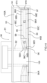
- FIG. 10 there is shown schematically a swather tractor 90 including a header 91 carried on front arms 92 of the tractor.
- the heard includes a front cutter bar 89 carried at the front of a frame 93 including end walls 94.
- a crop transportation system includes two drapers 95A and 95B carrying the cut crop to a center discharge 100 where the crop is discharged to the ground in the space between the drapers and behind the cutter bar 89.
- Each draper 95A, 95B comprises a draper belt 98 mounted on rollers 96 and 97 generally parallel to the forward direction so that the an upper run of the draper belt carries the crop transverse to the forward direction to the discharge end of the draper belt at the opening 100.
- the draper belt 98 has a front edge 98A adjacent the cutter bar and a rear edge 98B adjacent a back sheet 93A.
- the rollers thus include the discharge end roller 96 at the discharge end 100 and an outer end roller 97 at the end opposite the discharge end at the end sheet 94.
- the draper belt 98 is wrapped around the discharge end roller 96 and around the outer end roller 97.
- the outer end roller is carried on a first support arrangement 97A attached to the end sheet supporting the front and the rear ends of the outer end roller and including drive systems for the outer roller. This supports the outer roller 97 in a plane P1 of a main portion 98C of the belt.
- the belt is supported by one or more guide tracks 98D, 98E carried on the frame 93 so as to maintain the belt in the plane P1.
- the front and the rear ends 96B, 96A of the discharge end roller 96 are supported by a second support arrangement 96C forming part of the frame member 92 of the header.
- the support arrangement 96C supporting the front and the rear ends of the discharge end roller 96 support the discharge end roller in an operating position of which the axis 96D of the discharge end roller is at an angle to the plane P1 of the main portion 98C containing the axis 97B of the outer end roller 97.
- the draper belt may curve through a smooth curvature as it transitions between the angle of the axis 97B and the axis 96D with the curvature defined by the tracks 98D, 98E.
- the tracks may include a bend line 99 at which there is a sharp change in angle.
- the rear end 96A of the discharge end roller 96 is below the plane defined by the main or initial portion of the belt as defined by the axis 97B. this defines a plane P2 at the discharge end containing the axis 96D.
- This arrangement provides the discharge end roller 96 at an angle closer to the horizontal plane of the ground to reduce the change in discharge height from the front of the discharge roller to the rear.
- the angle of the roller 96 can thus be arranged as close as possible to horizontal but of course will change as the angle of the header is changed during operation.
- the support arrangement supporting the front and the rear ends of the discharge end roller provide an operating position of the discharge end roller in which the axis of the discharge end roller is at an angle to the plane P1 along the draper containing the axis of the outer end roller, with the rear end of the discharge end roller at a height below a height of the rear end of the outer end roller.
- the roller support arrangement holds the discharge end roller in a fixed positon relative to said plane along the draper and does not require the changes in angle which are provided in the embodiment described above.
- the angle may also be adjustable, for example in dependence on the changes in angle of the header.
Landscapes
- Life Sciences & Earth Sciences (AREA)
- Environmental Sciences (AREA)
- Soil Working Implements (AREA)
- Harvester Elements (AREA)
- Harvesting Machines For Specific Crops (AREA)
Claims (15)
- Tête de récolte (10) comprenant :une structure principale (13) s'étendant sur la largeur de la tête pour se déplacer vers l'avant, généralement à angle droit par rapport à la largeur, sur un sol comprenant une culture à récolter ;un ensemble de montage (11) pour porter la structure du cadre principal sur un véhicule de propulsion ;une barre de coupe (17) conçue pour se déplacer sur le sol dans une action de coupe et portant un couteau de coupe capable de couper la récolte lorsque la tête est déplacée vers l'avant sur le sol pour déposer la récolte sur la table (16) ;une drapeuse (18) comprenant une bande drapeuse (80) montée sur des rouleaux (81, 82) généralement parallèles à la direction d'avancement, de sorte qu'un parcours supérieur de la bande drapeuse transporte la récolte transversalement à la direction d'avancement jusqu'à une extrémité de décharge de la bande drapeuse ;la bande d'égouttage (80) a un bord avant (83) adjacent à la barre de coupe et un bord arrière (84) ;les rouleaux comprennent un rouleau d'extrémité de décharge (82) à l'extrémité de décharge et un rouleau d'extrémité extérieure (81) à l'extrémité opposée à l'extrémité de décharge, chacun ayant un axe de rouleau longitudinal ;la bande d'égouttage (80) est enroulée autour du rouleau d'évacuation (81) et autour du rouleau d'extrémité extérieure (82), l'extrémité avant de chacun des rouleaux d'évacuation et des rouleaux extérieurs se trouvant au niveau du bord avant de la bande ou à proximité de celui-ci et l'extrémité arrière des rouleaux d'évacuation et des rouleaux extérieurs se trouvant au niveau du bord arrière ou à proximité de celui-ci ;un premier dispositif de support (85A, 85B) supportant les extrémités avant et arrière du rouleau d'extrémité extérieur (81) ;un deuxième dispositif de support (85A, 85B ) supportant les extrémités avant et arrièredu rouleau d'extrémité de décharge (82) ; et caractérisé par le fait que les premier et second arrangements de support (85A, 85B) sont montés de telle sorte qu'au moins l'extrémité arrière (82D) du rouleau d'extrémité de décharge (82) est mobile dans une direction ascendante et descendante par rapport à l'extrémité arrière (81 D) du rouleau d'extrémité extérieur (81) de telle sorte que le rouleau d'extrémité de décharge (82) a une position de fonctionnement dans laquelle l'axe (82C) du rouleau d'extrémité de décharge est à un angle d'un plan le long de l'étireur contenant l'axe (81 A) du rouleau d'extrémité extérieur (81).
- La Tête de récolte (10) selon la revendication 1, dans lequel l'extrémité arrière (82D) du rouleau d'extrémité de décharge (82) est mobile à une hauteur inférieure à une hauteur de l'extrémité arrière (81 D) du rouleau d'extrémité extérieur (81) par rapport au plan le long du rouleau.
- La Tête de récolte (10) selon la revendication 1 ou 2, dans lequel l'extrémité arrière (82D) du rouleau d'extrémité de décharge (82) est mobile à une hauteur supérieure à une hauteur de l'extrémité arrière (81 D) du rouleau d'extrémité extérieur (81) par rapport au plan le long du rouleau.
- La Tête de récolte (10) selon toute revendication précédente, dans lequel le deuxième dispositif de support de rouleau (85B) maintient le rouleau d'extrémité de décharge (82) pour le mouvement de son axe afin de lever et d'abaisser l'extrémité arrière (82D) de celui-ci par rapport à l'extrémité avant.
- La Tête de récolte (10) selon toute revendication précédente, dans lequel le second dispositif de support de rouleau (85B) maintient le rouleau d'extrémité de décharge (82) pour un mouvement de son axe afin de lever et d'abaisser son extrémité arrière (82D), y compris une position dans laquelle l'axe du rouleau d'extrémité de décharge (82) se trouve dans le plan le long de l'égouttoir.
- La Tête de récolte (10) selon toute revendication précédente, dans lequel le deuxième dispositif de support de rouleau (85B) est conçu pour déplacer l'extrémité arrière (82D) du rouleau de décharge (82) dans une direction perpendiculaire au plan le long de l'égouttoir.
- La Tête de récolte (10) selon toute revendication précédente dans lequel il est prévu un élément de guidage (86) pour le brin supérieur de la bande d'égouttage (80) à une position espacée du rouleau d'extrémité de décharge (82) où l'élément de guidage (86) se trouve dans un plan commun avec le rouleau d'extrémité extérieur (81) de sorte qu'une partie principale (80M) du brin supérieur de la bande d'égouttage (80) se trouve dans un plan commun défini par l'élément de guidage (86) et le rouleau d'extrémité extérieur (81) et qu'une partie plus petite (80S) du brin supérieur de la bande d'égouttage (80) entre l'élément de guidage (86) et le rouleau d'extrémité de décharge (82) est tordue par rapport au plan commun.
- La tête de récolte (10) selon toute revendication précédente, dans laquelle le bord avant (83) de la bande d'égouttage (80) est situé à une position fixe adjacente à la barre de coupe (17) pour recevoir la récolte.
- La tête de récolte (10) selon toute revendication précédente, comprenant en outre : un second drapeur symétrique au drapeur et alimentant la récolte à partir d'une extrémité respective de la tête de récolte vers une section d'alimentation centrale (18B) de la tête de récolte ;un drapeur d'alimentation (23) ayant un rouleau avant (24) derrière la barre de coupe (17) et parallèle à celle-ci et un rouleau arrière (25) espacé vers l'arrière du rouleau avant de sorte que la récolte déchargée de l'extrémité de décharge du drapeur et du second drapeur tombe sur le drapeur d'alimentation (23) pour être transportée vers l'arrière ;un élément de fixation (11) pour la fixation de la structure du cadre principal (13) à une chambre d'alimentation (12) d'une moissonneuse ;un dispositif de suspension reliant la structure principale (13) à l'élément de fixation (11) pour un mouvement flottant de haut en bas de la structure principale (13) et de la barre de coupe (17) par rapport à l'élément de fixation :
dans lequel le rouleau arrière (25) de l'extracteur d'alimentation est monté par rapport à l'élément de fixation (11) pour se déplacer vers le haut et vers le bas par rapport à la barre de coupe (17) et au rouleau avant (24) afin de s'adapter aux changements de position entre la barre de coupe (17) et la chambre d'alimentation (12) causés par ledit mouvement flottant vers le haut et vers le bas :
et dans lequel l'extrémité arrière (82D) du rouleau de décharge (82) est conçue pour se déplacer vers le haut et vers le bas au moins en partie en réponse au mouvement du rouleau arrière (25). - La Tête de récolte (10) selon la revendication 9, dans lequel l'extrémité arrière (82D) du rouleau de décharge (82) est portée par un support (25A) fixé par rapport au rouleau arrière (25) de manière à suivre directement le mouvement du rouleau arrière (25).
- La Tête de récolte (10) selon l'une quelconque des revendications 9 à 10, dans lequel le rouleau d'extrémité de décharge (82) recouvre le bord de l'égouttoir d'alimentation (23).
- La Tête de récolte (10) selon toute revendication précédente, dans lequel une partie principale (80M) de la courroie d'égouttage (80) s'étendant du rouleau extérieur (81) vers l'intérieur se trouve dans un plan incliné vers le haut et vers l'arrière par rapport à la barre de coupe (17).
- La Tête de récolte (10) selon l'une des revendications 9 à 12, dans lequel le rouleau arrière (25) du drapeur d'alimentation (23) et l'extrémité arrière (82D) du rouleau d'évacuation (82) du drapeur et du second drapeur sont tous reliés à l'élément de fixation (11) pour se déplacer avec la chambre d'alimentation.
- La Tête de récolte (10) selon l'une quelconque des revendications 9 à 13, dans lequel le rouleau avant (24) du drapeur d'alimentation (23), l'extrémité avant du rouleau de décharge (82) du drapeur et du second drapeur sont tous reliés à la structure du cadre principal (13) pour se déplacer avec elle.
- La Tête de récolte (10) selon l'une des revendications 9 à 14, dans lequel la structure du cadre principal (13) comprend une section centrale (10A) montée sur l'élément de fixation (11) et deux sections d'aile (10B, 10C) montées sur la section centrale (10A) pour un mouvement pivotant autour d'un axe généralement parallèle à la direction vers l'avant.
Applications Claiming Priority (2)
| Application Number | Priority Date | Filing Date | Title |
|---|---|---|---|
| US201762537245P | 2017-07-26 | 2017-07-26 | |
| PCT/CA2018/050876 WO2019018923A1 (fr) | 2017-07-26 | 2018-07-19 | Collecteur pour une machine de récolte de récolte ayant un tablier latéral torsadé |
Publications (3)
| Publication Number | Publication Date |
|---|---|
| EP3657930A1 EP3657930A1 (fr) | 2020-06-03 |
| EP3657930A4 EP3657930A4 (fr) | 2021-04-14 |
| EP3657930B1 true EP3657930B1 (fr) | 2023-08-16 |
Family
ID=65039238
Family Applications (1)
| Application Number | Title | Priority Date | Filing Date |
|---|---|---|---|
| EP18837627.1A Active EP3657930B1 (fr) | 2017-07-26 | 2018-07-19 | Collecteur pour une machine de récolte ayant un tablier latéral torsadé |
Country Status (7)
| Country | Link |
|---|---|
| US (1) | US11849675B2 (fr) |
| EP (1) | EP3657930B1 (fr) |
| AU (1) | AU2018305787B2 (fr) |
| BR (1) | BR112020001593A2 (fr) |
| CA (1) | CA3070236A1 (fr) |
| HU (1) | HUE064270T2 (fr) |
| WO (1) | WO2019018923A1 (fr) |
Families Citing this family (4)
| Publication number | Priority date | Publication date | Assignee | Title |
|---|---|---|---|---|
| US11510367B2 (en) * | 2019-05-13 | 2022-11-29 | Macdon Industries Ltd. | Draper header for a crop harvesting machine |
| EP3982712B1 (fr) * | 2019-06-12 | 2025-02-26 | CNH Industrial Belgium NV | Bras de rabatteur réglable |
| CN112840837B (zh) * | 2020-12-31 | 2022-02-08 | 安徽工程大学 | 农业收割机的使用方法 |
| DE102022127703A1 (de) | 2022-10-20 | 2024-04-25 | Deere & Company | Erntevorsatz zur Ganzpflanzenernte |
Family Cites Families (21)
| Publication number | Priority date | Publication date | Assignee | Title |
|---|---|---|---|---|
| US635264A (en) * | 1899-04-04 | 1899-10-17 | James C Lynch | Grain-header. |
| US1509124A (en) * | 1922-11-25 | 1924-09-23 | Bloor Frank | Trailer feeder attachment for combined harvester thrashers |
| US3304699A (en) * | 1964-08-11 | 1967-02-21 | Sperry Rand Corp | Harvester header construction |
| US5005343A (en) * | 1988-06-22 | 1991-04-09 | Macdon Industries Ltd. | Header for a combine harvesting machine |
| US4956966A (en) * | 1988-06-22 | 1990-09-18 | Macdon Industries Ltd. | Header for a combine harvesting machine |
| US20080271426A1 (en) * | 2006-02-10 | 2008-11-06 | Agco Corporation | Draper belt with crop-retaining rib |
| US20070193243A1 (en) * | 2006-02-10 | 2007-08-23 | Schmidt James R | Combine Harvester Draper Header Having Flexible Cutterbar |
| US20090277148A1 (en) * | 2008-05-09 | 2009-11-12 | Agco Corporation | Flexible draper and cutter bar having shiftable crop divider with deflector |
| US20090277145A1 (en) * | 2008-05-09 | 2009-11-12 | Agco Corporation | Header height control system with multiple potentiometer input |
| US7958711B1 (en) * | 2010-06-16 | 2011-06-14 | Agco Corporation | Crop deflector for ends of draper belt of flexible draper header |
| US8065865B1 (en) * | 2010-08-17 | 2011-11-29 | Deere & Company | Spring assisted translating draper belt drive rollers for an agricultural harvesting machine |
| US8087224B1 (en) * | 2010-09-16 | 2012-01-03 | Deere & Company | Flexible draper platform with pivot geometry |
| US8495855B1 (en) * | 2012-04-05 | 2013-07-30 | Deere & Company | Draper header with pivoting conveyor rollers |
| US8695315B2 (en) * | 2012-08-09 | 2014-04-15 | Deere & Company | Draper header with pivoting side draper conveyors |
| US8752359B2 (en) * | 2012-08-31 | 2014-06-17 | Macdon Industries Ltd. | Draper support of a crop harvesting header |
| US9402343B1 (en) * | 2015-04-23 | 2016-08-02 | Jose Luis Allochis | Flexible cutterbar assembly for a harvesting platform |
| US10292331B2 (en) * | 2017-06-30 | 2019-05-21 | Cnh Industrial America Llc | Draper belt system with frame pivot joint and roller sharing same axis |
| US10349580B2 (en) * | 2017-07-06 | 2019-07-16 | Mac Don Industries Ltd. | Draper header for attachment to a harvesting machine |
| US20190029177A1 (en) * | 2017-07-27 | 2019-01-31 | Macdon Industries Ltd. | Header for a Crop Harvesting Machine |
| CA2974636A1 (fr) * | 2017-07-27 | 2019-01-27 | Macdon Industries Ltd. | Bec cueilleur pour machine de recolte de culture |
| CA3026913C (fr) * | 2018-12-10 | 2020-07-14 | Macdon Industries Ltd. | Andaineuse comportant un couteau de recolte flexible |
-
2018
- 2018-07-19 BR BR112020001593-8A patent/BR112020001593A2/pt active Search and Examination
- 2018-07-19 WO PCT/CA2018/050876 patent/WO2019018923A1/fr not_active Ceased
- 2018-07-19 AU AU2018305787A patent/AU2018305787B2/en active Active
- 2018-07-19 CA CA3070236A patent/CA3070236A1/fr active Pending
- 2018-07-19 HU HUE18837627A patent/HUE064270T2/hu unknown
- 2018-07-19 EP EP18837627.1A patent/EP3657930B1/fr active Active
- 2018-07-19 US US16/632,134 patent/US11849675B2/en active Active
Also Published As
| Publication number | Publication date |
|---|---|
| AU2018305787B2 (en) | 2024-08-15 |
| BR112020001593A2 (pt) | 2020-07-21 |
| EP3657930A1 (fr) | 2020-06-03 |
| CA3070236A1 (fr) | 2019-01-31 |
| US11849675B2 (en) | 2023-12-26 |
| HUE064270T2 (hu) | 2024-03-28 |
| EP3657930A4 (fr) | 2021-04-14 |
| WO2019018923A1 (fr) | 2019-01-31 |
| US20200229347A1 (en) | 2020-07-23 |
| AU2018305787A1 (en) | 2020-02-13 |
Similar Documents
| Publication | Publication Date | Title |
|---|---|---|
| US11632902B2 (en) | Draper header with flexible crop cutting knife | |
| US7918076B2 (en) | Device for maintaining wing balance on a multi-section header | |
| CA2913937C (fr) | Roues de jauge pour un organe de coupe agricole a plusieurs sections | |
| EP3657930B1 (fr) | Collecteur pour une machine de récolte ayant un tablier latéral torsadé | |
| US6865871B2 (en) | Crop feed arrangement for the header of a combine harvester | |
| EP1401256B1 (fr) | Tete de coupe en plusieurs parties a lame de coupe flexible | |
| US20190029177A1 (en) | Header for a Crop Harvesting Machine | |
| AU2002257470A1 (en) | Multi-section header with flexible crop cutting knife | |
| CA3026913C (fr) | Andaineuse comportant un couteau de recolte flexible | |
| EP3466241B1 (fr) | Tête de récolte agricole comportant des pivots de bras de flotteur en dessous des couteaux à mouvement alternatif | |
| EP3434095A1 (fr) | Tête pour machine de récolte | |
| AU2020204231B2 (en) | Multi-section header with flexible crop cutting knife | |
| AU2019204082B2 (en) | A crop harvesting header |
Legal Events
| Date | Code | Title | Description |
|---|---|---|---|
| STAA | Information on the status of an ep patent application or granted ep patent |
Free format text: STATUS: THE INTERNATIONAL PUBLICATION HAS BEEN MADE |
|
| PUAI | Public reference made under article 153(3) epc to a published international application that has entered the european phase |
Free format text: ORIGINAL CODE: 0009012 |
|
| STAA | Information on the status of an ep patent application or granted ep patent |
Free format text: STATUS: REQUEST FOR EXAMINATION WAS MADE |
|
| 17P | Request for examination filed |
Effective date: 20200219 |
|
| AK | Designated contracting states |
Kind code of ref document: A1 Designated state(s): AL AT BE BG CH CY CZ DE DK EE ES FI FR GB GR HR HU IE IS IT LI LT LU LV MC MK MT NL NO PL PT RO RS SE SI SK SM TR |
|
| AX | Request for extension of the european patent |
Extension state: BA ME |
|
| DAV | Request for validation of the european patent (deleted) | ||
| DAX | Request for extension of the european patent (deleted) | ||
| REG | Reference to a national code |
Ref country code: DE Ref legal event code: R079 Free format text: PREVIOUS MAIN CLASS: A01D0041060000 Ipc: A01D0061020000 Ref country code: DE Ref legal event code: R079 Ref document number: 602018055618 Country of ref document: DE Free format text: PREVIOUS MAIN CLASS: A01D0041060000 Ipc: A01D0061020000 |
|
| A4 | Supplementary search report drawn up and despatched |
Effective date: 20210317 |
|
| RIC1 | Information provided on ipc code assigned before grant |
Ipc: A01D 61/02 20060101AFI20210311BHEP Ipc: A01D 41/14 20060101ALI20210311BHEP Ipc: A01D 57/20 20060101ALI20210311BHEP |
|
| GRAP | Despatch of communication of intention to grant a patent |
Free format text: ORIGINAL CODE: EPIDOSNIGR1 |
|
| STAA | Information on the status of an ep patent application or granted ep patent |
Free format text: STATUS: GRANT OF PATENT IS INTENDED |
|
| INTG | Intention to grant announced |
Effective date: 20230320 |
|
| GRAS | Grant fee paid |
Free format text: ORIGINAL CODE: EPIDOSNIGR3 |
|
| GRAA | (expected) grant |
Free format text: ORIGINAL CODE: 0009210 |
|
| STAA | Information on the status of an ep patent application or granted ep patent |
Free format text: STATUS: THE PATENT HAS BEEN GRANTED |
|
| AK | Designated contracting states |
Kind code of ref document: B1 Designated state(s): AL AT BE BG CH CY CZ DE DK EE ES FI FR GB GR HR HU IE IS IT LI LT LU LV MC MK MT NL NO PL PT RO RS SE SI SK SM TR |
|
| REG | Reference to a national code |
Ref country code: CH Ref legal event code: EP |
|
| REG | Reference to a national code |
Ref country code: DE Ref legal event code: R096 Ref document number: 602018055618 Country of ref document: DE |
|
| REG | Reference to a national code |
Ref country code: IE Ref legal event code: FG4D |
|
| REG | Reference to a national code |
Ref country code: LT Ref legal event code: MG9D |
|
| REG | Reference to a national code |
Ref country code: NL Ref legal event code: MP Effective date: 20230816 |
|
| REG | Reference to a national code |
Ref country code: AT Ref legal event code: MK05 Ref document number: 1599067 Country of ref document: AT Kind code of ref document: T Effective date: 20230816 |
|
| PG25 | Lapsed in a contracting state [announced via postgrant information from national office to epo] |
Ref country code: GR Free format text: LAPSE BECAUSE OF FAILURE TO SUBMIT A TRANSLATION OF THE DESCRIPTION OR TO PAY THE FEE WITHIN THE PRESCRIBED TIME-LIMIT Effective date: 20231117 |
|
| PG25 | Lapsed in a contracting state [announced via postgrant information from national office to epo] |
Ref country code: IS Free format text: LAPSE BECAUSE OF FAILURE TO SUBMIT A TRANSLATION OF THE DESCRIPTION OR TO PAY THE FEE WITHIN THE PRESCRIBED TIME-LIMIT Effective date: 20231216 |
|
| PG25 | Lapsed in a contracting state [announced via postgrant information from national office to epo] |
Ref country code: SE Free format text: LAPSE BECAUSE OF FAILURE TO SUBMIT A TRANSLATION OF THE DESCRIPTION OR TO PAY THE FEE WITHIN THE PRESCRIBED TIME-LIMIT Effective date: 20230816 Ref country code: RS Free format text: LAPSE BECAUSE OF FAILURE TO SUBMIT A TRANSLATION OF THE DESCRIPTION OR TO PAY THE FEE WITHIN THE PRESCRIBED TIME-LIMIT Effective date: 20230816 Ref country code: PT Free format text: LAPSE BECAUSE OF FAILURE TO SUBMIT A TRANSLATION OF THE DESCRIPTION OR TO PAY THE FEE WITHIN THE PRESCRIBED TIME-LIMIT Effective date: 20231218 Ref country code: NO Free format text: LAPSE BECAUSE OF FAILURE TO SUBMIT A TRANSLATION OF THE DESCRIPTION OR TO PAY THE FEE WITHIN THE PRESCRIBED TIME-LIMIT Effective date: 20231116 Ref country code: NL Free format text: LAPSE BECAUSE OF FAILURE TO SUBMIT A TRANSLATION OF THE DESCRIPTION OR TO PAY THE FEE WITHIN THE PRESCRIBED TIME-LIMIT Effective date: 20230816 Ref country code: LV Free format text: LAPSE BECAUSE OF FAILURE TO SUBMIT A TRANSLATION OF THE DESCRIPTION OR TO PAY THE FEE WITHIN THE PRESCRIBED TIME-LIMIT Effective date: 20230816 Ref country code: LT Free format text: LAPSE BECAUSE OF FAILURE TO SUBMIT A TRANSLATION OF THE DESCRIPTION OR TO PAY THE FEE WITHIN THE PRESCRIBED TIME-LIMIT Effective date: 20230816 Ref country code: IS Free format text: LAPSE BECAUSE OF FAILURE TO SUBMIT A TRANSLATION OF THE DESCRIPTION OR TO PAY THE FEE WITHIN THE PRESCRIBED TIME-LIMIT Effective date: 20231216 Ref country code: HR Free format text: LAPSE BECAUSE OF FAILURE TO SUBMIT A TRANSLATION OF THE DESCRIPTION OR TO PAY THE FEE WITHIN THE PRESCRIBED TIME-LIMIT Effective date: 20230816 Ref country code: GR Free format text: LAPSE BECAUSE OF FAILURE TO SUBMIT A TRANSLATION OF THE DESCRIPTION OR TO PAY THE FEE WITHIN THE PRESCRIBED TIME-LIMIT Effective date: 20231117 Ref country code: FI Free format text: LAPSE BECAUSE OF FAILURE TO SUBMIT A TRANSLATION OF THE DESCRIPTION OR TO PAY THE FEE WITHIN THE PRESCRIBED TIME-LIMIT Effective date: 20230816 Ref country code: AT Free format text: LAPSE BECAUSE OF FAILURE TO SUBMIT A TRANSLATION OF THE DESCRIPTION OR TO PAY THE FEE WITHIN THE PRESCRIBED TIME-LIMIT Effective date: 20230816 |
|
| PG25 | Lapsed in a contracting state [announced via postgrant information from national office to epo] |
Ref country code: PL Free format text: LAPSE BECAUSE OF FAILURE TO SUBMIT A TRANSLATION OF THE DESCRIPTION OR TO PAY THE FEE WITHIN THE PRESCRIBED TIME-LIMIT Effective date: 20230816 |
|
| REG | Reference to a national code |
Ref country code: HU Ref legal event code: AG4A Ref document number: E064270 Country of ref document: HU |
|
| PG25 | Lapsed in a contracting state [announced via postgrant information from national office to epo] |
Ref country code: ES Free format text: LAPSE BECAUSE OF FAILURE TO SUBMIT A TRANSLATION OF THE DESCRIPTION OR TO PAY THE FEE WITHIN THE PRESCRIBED TIME-LIMIT Effective date: 20230816 |
|
| PG25 | Lapsed in a contracting state [announced via postgrant information from national office to epo] |
Ref country code: SM Free format text: LAPSE BECAUSE OF FAILURE TO SUBMIT A TRANSLATION OF THE DESCRIPTION OR TO PAY THE FEE WITHIN THE PRESCRIBED TIME-LIMIT Effective date: 20230816 Ref country code: RO Free format text: LAPSE BECAUSE OF FAILURE TO SUBMIT A TRANSLATION OF THE DESCRIPTION OR TO PAY THE FEE WITHIN THE PRESCRIBED TIME-LIMIT Effective date: 20230816 Ref country code: ES Free format text: LAPSE BECAUSE OF FAILURE TO SUBMIT A TRANSLATION OF THE DESCRIPTION OR TO PAY THE FEE WITHIN THE PRESCRIBED TIME-LIMIT Effective date: 20230816 Ref country code: EE Free format text: LAPSE BECAUSE OF FAILURE TO SUBMIT A TRANSLATION OF THE DESCRIPTION OR TO PAY THE FEE WITHIN THE PRESCRIBED TIME-LIMIT Effective date: 20230816 Ref country code: DK Free format text: LAPSE BECAUSE OF FAILURE TO SUBMIT A TRANSLATION OF THE DESCRIPTION OR TO PAY THE FEE WITHIN THE PRESCRIBED TIME-LIMIT Effective date: 20230816 Ref country code: CZ Free format text: LAPSE BECAUSE OF FAILURE TO SUBMIT A TRANSLATION OF THE DESCRIPTION OR TO PAY THE FEE WITHIN THE PRESCRIBED TIME-LIMIT Effective date: 20230816 Ref country code: SK Free format text: LAPSE BECAUSE OF FAILURE TO SUBMIT A TRANSLATION OF THE DESCRIPTION OR TO PAY THE FEE WITHIN THE PRESCRIBED TIME-LIMIT Effective date: 20230816 |
|
| REG | Reference to a national code |
Ref country code: DE Ref legal event code: R097 Ref document number: 602018055618 Country of ref document: DE |
|
| PLBE | No opposition filed within time limit |
Free format text: ORIGINAL CODE: 0009261 |
|
| STAA | Information on the status of an ep patent application or granted ep patent |
Free format text: STATUS: NO OPPOSITION FILED WITHIN TIME LIMIT |
|
| 26N | No opposition filed |
Effective date: 20240517 |
|
| PG25 | Lapsed in a contracting state [announced via postgrant information from national office to epo] |
Ref country code: SI Free format text: LAPSE BECAUSE OF FAILURE TO SUBMIT A TRANSLATION OF THE DESCRIPTION OR TO PAY THE FEE WITHIN THE PRESCRIBED TIME-LIMIT Effective date: 20230816 |
|
| PG25 | Lapsed in a contracting state [announced via postgrant information from national office to epo] |
Ref country code: BG Free format text: LAPSE BECAUSE OF FAILURE TO SUBMIT A TRANSLATION OF THE DESCRIPTION OR TO PAY THE FEE WITHIN THE PRESCRIBED TIME-LIMIT Effective date: 20230816 |
|
| PG25 | Lapsed in a contracting state [announced via postgrant information from national office to epo] |
Ref country code: BG Free format text: LAPSE BECAUSE OF FAILURE TO SUBMIT A TRANSLATION OF THE DESCRIPTION OR TO PAY THE FEE WITHIN THE PRESCRIBED TIME-LIMIT Effective date: 20230816 |
|
| PG25 | Lapsed in a contracting state [announced via postgrant information from national office to epo] |
Ref country code: MC Free format text: LAPSE BECAUSE OF FAILURE TO SUBMIT A TRANSLATION OF THE DESCRIPTION OR TO PAY THE FEE WITHIN THE PRESCRIBED TIME-LIMIT Effective date: 20230816 |
|
| REG | Reference to a national code |
Ref country code: CH Ref legal event code: PL |
|
| PG25 | Lapsed in a contracting state [announced via postgrant information from national office to epo] |
Ref country code: LU Free format text: LAPSE BECAUSE OF NON-PAYMENT OF DUE FEES Effective date: 20240719 |
|
| PG25 | Lapsed in a contracting state [announced via postgrant information from national office to epo] |
Ref country code: LU Free format text: LAPSE BECAUSE OF NON-PAYMENT OF DUE FEES Effective date: 20240719 |
|
| PG25 | Lapsed in a contracting state [announced via postgrant information from national office to epo] |
Ref country code: BE Free format text: LAPSE BECAUSE OF NON-PAYMENT OF DUE FEES Effective date: 20240731 Ref country code: CH Free format text: LAPSE BECAUSE OF NON-PAYMENT OF DUE FEES Effective date: 20240731 |
|
| REG | Reference to a national code |
Ref country code: BE Ref legal event code: MM Effective date: 20240731 |
|
| PG25 | Lapsed in a contracting state [announced via postgrant information from national office to epo] |
Ref country code: IE Free format text: LAPSE BECAUSE OF NON-PAYMENT OF DUE FEES Effective date: 20240719 |
|
| PGFP | Annual fee paid to national office [announced via postgrant information from national office to epo] |
Ref country code: HU Payment date: 20250723 Year of fee payment: 8 |
|
| PGFP | Annual fee paid to national office [announced via postgrant information from national office to epo] |
Ref country code: DE Payment date: 20250731 Year of fee payment: 8 |
|
| PGFP | Annual fee paid to national office [announced via postgrant information from national office to epo] |
Ref country code: IT Payment date: 20250724 Year of fee payment: 8 |
|
| PGFP | Annual fee paid to national office [announced via postgrant information from national office to epo] |
Ref country code: GB Payment date: 20250722 Year of fee payment: 8 |
|
| PGFP | Annual fee paid to national office [announced via postgrant information from national office to epo] |
Ref country code: FR Payment date: 20250725 Year of fee payment: 8 |
|
| PG25 | Lapsed in a contracting state [announced via postgrant information from national office to epo] |
Ref country code: CY Free format text: LAPSE BECAUSE OF FAILURE TO SUBMIT A TRANSLATION OF THE DESCRIPTION OR TO PAY THE FEE WITHIN THE PRESCRIBED TIME-LIMIT; INVALID AB INITIO Effective date: 20180719 |