EP3658290B1 - Fluidisches bauteil - Google Patents
Fluidisches bauteil Download PDFInfo
- Publication number
- EP3658290B1 EP3658290B1 EP18750113.5A EP18750113A EP3658290B1 EP 3658290 B1 EP3658290 B1 EP 3658290B1 EP 18750113 A EP18750113 A EP 18750113A EP 3658290 B1 EP3658290 B1 EP 3658290B1
- Authority
- EP
- European Patent Office
- Prior art keywords
- outlet
- component
- channel
- oscillation
- boundary wall
- Prior art date
- Legal status (The legal status is an assumption and is not a legal conclusion. Google has not performed a legal analysis and makes no representation as to the accuracy of the status listed.)
- Active
Links
Images








Classifications
-
- B—PERFORMING OPERATIONS; TRANSPORTING
- B05—SPRAYING OR ATOMISING IN GENERAL; APPLYING FLUENT MATERIALS TO SURFACES, IN GENERAL
- B05B—SPRAYING APPARATUS; ATOMISING APPARATUS; NOZZLES
- B05B1/00—Nozzles, spray heads or other outlets, with or without auxiliary devices such as valves, heating means
- B05B1/02—Nozzles, spray heads or other outlets, with or without auxiliary devices such as valves, heating means designed to produce a jet, spray, or other discharge of particular shape or nature, e.g. in single drops, or having an outlet of particular shape
- B05B1/08—Nozzles, spray heads or other outlets, with or without auxiliary devices such as valves, heating means designed to produce a jet, spray, or other discharge of particular shape or nature, e.g. in single drops, or having an outlet of particular shape of pulsating nature, e.g. delivering liquid in successive separate quantities
-
- B—PERFORMING OPERATIONS; TRANSPORTING
- B05—SPRAYING OR ATOMISING IN GENERAL; APPLYING FLUENT MATERIALS TO SURFACES, IN GENERAL
- B05B—SPRAYING APPARATUS; ATOMISING APPARATUS; NOZZLES
- B05B1/00—Nozzles, spray heads or other outlets, with or without auxiliary devices such as valves, heating means
- B05B1/12—Nozzles, spray heads or other outlets, with or without auxiliary devices such as valves, heating means capable of producing different kinds of discharge, e.g. either jet or spray
Definitions
- the invention relates to a fluidic component according to the preamble of claim 1 and a fluid distribution device that includes such a fluidic component.
- fluid jets In fluid distribution devices such as cleaning devices, it is desirable to be able to generate fluid jets with different spray characteristics in order to meet the requirements in different areas of use. For example, there is a need for a device that can selectively generate omnidirectional and fan beams. In this way, stubborn dirt can be treated and cleaned with the high jet impulse of an omnidirectional jet and sensitive surfaces can be treated and cleaned extensively with the locally lower jet impulse of a fan jet (i.e. with a lower area performance). A fan jet or a fluid jet with a large spatial distribution of the fluid is well suited for rinsing.
- nozzle systems are known from the prior art in which, for example, a slide or a rotary mechanism is used to switch back and forth between a plurality of nozzles, each with different spray characteristics.
- Each nozzle has a defined and unchangeable spray characteristic and gives the fluid jet a jet shape.
- nozzle systems generate quasi-static or static and non-oscillating fluid jets.
- nozzles are known from the prior art, which are set in motion by means of kinematics or a (movable) device.
- the kinematics or (moving) device includes moving components that are subject to high wear are exposed. The costs associated with manufacture and maintenance are correspondingly high.
- due to the moving components a relatively large installation space is required overall.
- fluidic components In order to generate a moving fluid flow (or fluid jet), fluidic components are also known which generate a fluid jet oscillating in one plane.
- the fluidic components do not include any moving components that serve to generate a moving fluid flow. As a result, they do not have the disadvantages resulting from the moving components compared to the nozzles with moving components.
- the fluidic component is intended to generate a moving, oscillating or pulsating fluid jet.
- fluid flow patterns of an oscillating jet are sinusoidal jet oscillations, rectangular, sawtooth or triangular jets, spatial or temporal jet pulsations and switching.
- Such fluid jets are used, for example, to evenly distribute a fluid jet (or fluid stream) over a target area.
- the fluid flow can be a liquid flow, a gas flow, a multi-phase flow (for example wet steam) or a fluid containing particles.
- the fluidic components known from the prior art for generating a moving fluid flow usually have a fixed spray property with a constant volume flow and/or inlet pressure of the fluid.
- US 6,497,375 B1 and WO 02/07893 A1 fluidic components with different operating points are described, at which air can be directed into the fluidic components by means of closable air penetration holes and the oscillation can be switched on and off in a targeted manner. It is thus possible to switch between a spray jet with a fixed oscillation angle and a punctiform spray jet. From the U.S.
- a device which comprises a plurality of fluidic components, each with different spray properties, of which one fluidic component can optionally be rotated into the fluid jet and thus (depending on the choice of fluidic component) a fluid flow with different spray properties can be generated.
- Such a device requires a relatively large amount of space overall.
- the spray characteristics of the exiting fluid flow can only be varied between a predetermined number of possibilities.
- the object of the present invention is to create a device that is designed to generate a moving fluid jet, the spray characteristics of which can be set before operation or changed during operation, the device having a high level of reliability and correspondingly low maintenance costs.
- the fluidic component comprises a flow chamber through which a fluid stream can flow, which enters the flow chamber through an inlet opening of the flow chamber and exits the flow chamber through an outlet opening of the flow chamber.
- the inlet port and the outlet port are located on opposite sides of the flow chamber.
- At least one means for generating an oscillation of the fluid flow at the outlet opening is provided in the flow chamber.
- the means for forming an oscillation can be at least one bypass channel, for example. Alternatively, other means for forming an oscillation of the fluid flow can also be provided.
- the fluidic component is characterized in that the flow chamber has a changeable shape.
- a device can be provided which acts in a targeted manner on the fluidic component and thus brings about a change in the shape of the flow chamber.
- the change in shape of the flow chamber is preferably reversible. This means that the device can bring about a change in shape and also reverse it again.
- various parameters of the fluidic component such as the shape or the volume, can be changed. This allows the spray characteristics of the exiting fluid stream to be changed without changing the parameters of the fluid flowing through the fluidic component, such as the type of fluid, the inlet pressure of the fluid, the inlet velocity of the fluid and the volumetric flow rate.
- the shape can be changed steplessly (or alternatively in steps), so that the spray characteristics of the emerging fluid flow also change steplessly (in steps) and can thus be specifically adapted to a specific application.
- the spray characteristics can relate in particular to the spray angle that is achieved by means of the invention fluidic component is adjustable.
- the exiting fluid jet can be modulated between a point jet and a fan jet.
- the fluidic component according to the invention can be used to generate a directed fluid jet with adjustable spray characteristics for targeted wetting, dripping or sweeping over a surface. Since the fluidic component according to the invention allows the emerging fluid flow to perform an oscillating movement and its spray properties to be adjusted, the cleaning, surface wetting or surface treatment performance can be massively increased.
- the fluidic component can be adapted to different cleaning requirements.
- the fluidic component according to the invention is therefore of interest for high, medium and low-pressure cleaning, as well as for surface treatment and surface coating.
- the change in the shape of the flow chamber can take place before the fluidic component is put into operation or during operation, that is to say while a fluid is flowing through the fluidic component.
- the fluid entering the flow chamber through the inlet port may be pressurized from 0.001 to 6000 bar (relative to ambient pressure).
- the pressure can be between 0.005 and 1800 bar.
- a pressure range between 0.05 and 1100 bar is particularly preferred.
- so-called low-pressure applications such as washing machines, dishwashers and fluid distribution devices (sprinklers, hand showers or cleaning systems)
- an inlet pressure of 0.01 bar to 12 bar above ambient pressure is advantageous.
- the inlet pressure is preferably between 6 bar and 120 bar above ambient pressure.
- the inlet pressure can be over 40 bar.
- the oscillation frequency of the oscillating fluid flow emerging from the fluidic component can be between 0.25 Hz and 40 kHz.
- a preferred frequency range is between 3 Hz and 600 Hz.
- the fluid can be a gaseous, liquid or multi-phase, free-flowing medium, which can also be afflicted with particles.
- the fluid is a liquid (e.g. water)
- the geometric parameters (shape, size, number and shape of the bypass channels, (relative) size of the inlet and outlet openings) of the fluidic component are selected in such a way that the pressure to which the fluid flow is subjected when it passes through the inlet opening enters the fluidic component, is essentially broken down at the outlet opening.
- the parameters can be selected such that the pressure to which the fluid flow is subjected when it enters the fluidic component via the inlet opening is already reduced before (upstream) the outlet opening.
- the flow chamber is delimited by a boundary wall.
- the boundary wall does not have to form the external appearance of the fluidic component.
- the boundary wall can be formed by the inner surface of a hollow body, with the cavity of the hollow body forming the flow chamber.
- the outer appearance of the fluidic component is then defined by the outer surface of the hollow body.
- the outer surface of the hollow body can in particular be essentially cuboid and have interruptions for the inlet opening and the outlet opening.
- the flow chamber has a main flow channel, which connects the inlet opening and the outlet opening to one another, and at least one secondary flow channel as a means for creating an oscillation of the fluid flow at the outlet opening.
- the direction from the inlet opening to the outlet opening can be regarded as the main flow direction of the fluid flow.
- the main flow channel and the at least one secondary flow channel are separated from one another by at least one inner block, so that the main flow channel, the at least one inner block and the at least one secondary flow channel are arranged essentially in one plane.
- the exiting fluid flow then oscillates in a plane of oscillation that corresponds to the plane defined by the main flow channel, the at least one inner block and the at least one side flow channel.
- the flow chamber can have two secondary flow ducts which lie in one plane with the main flow duct, the main flow duct (viewed transversely to the main flow direction) lying between the two secondary flow ducts.
- each bypass duct is separated from the main flow duct by at least one internal block.
- the secondary flow channels can each have an input and an output via which they are fluidically connected to the main flow channel.
- the boundary wall can have at least one section that is deformable.
- the at least one section can have different material properties compared to the rest of the boundary wall, such as material thickness or extensibility (elasticity).
- the at least one deformable section of the boundary wall can then be deformed under the targeted action of an external force.
- a targeted action of an external force is not to be understood in particular as the pressure of the fluid flowing through the fluidic component. Rather, a device for exerting the external force can be provided, which can be actuated by a user. This also applies to the other embodiments.
- an internal force which essentially results from the pressure of the fluid flowing through the fluidic component, can be used to deform the at least one deformable (e.g. elastic) section of the boundary wall in a targeted manner .
- the at least one deformable section can be designed in such a way that it can be reversibly deformed by the action of the internal force, i.e. it changes from a first to a second configuration when the mass flow at the inlet opening (the input pressure) increases and when the mass flow falls at the inlet port (of the inlet pressure) returns from the second to the first configuration.
- the transition between more than two configurations or a stepless transition is also conceivable.
- the mass flow-dependent deformation of the at least one deformable section of the boundary wall and depending on the specific position of the at least one deformable section in the flow chamber and in particular at the outlet opening can be used to set an almost constant pressure or volume flow.
- the fluidic component can become a so-called self-regulating system that has an almost constantly high volume flow at the outlet opening despite the varying admission pressure or fluid inlet pressure and generates an almost constant droplet spectrum.
- the spray angle of the exiting fluid flow can remain almost constant or decrease (increase).
- the at least one deformable section of the boundary wall can be designed as an elastically deformable wall delimiting the outlet opening (transverse to the direction of fluid flow), which deforms when the fluid pressure at the outlet opening changes and the cross-sectional area of the outlet opening changes to such an extent that the resulting droplet sizes of the exiting Fluid stream are hardly dependent on the admission pressure, and that the pressure at the outlet port essentially returns to the previously prevailing level or remains at this level.
- the Sauter diameter of the droplets of the exiting fluid flow decreases less sharply in comparison to an almost rigid, unchangeable system with increasing inlet pressure, or remains almost stable despite increasing inlet pressure.
- the material of the at least one deformable section of the boundary wall should be selected in such a way that it does not deform at any pressure of the fluid flowing through the fluidic component, which exerts the so-called internal force on the at least one deformable section, but only at a predetermined pressure Pressure range or pressure change range.
- the fluidic component according to the invention can be used for various applications in which, on the one hand, the dimensions of the fluidic component and, on the other hand, the volume flow to be provided at the outlet opening can vary to a greater or lesser extent. The narrowest point of the fluidic component through which a flow can flow plays a particularly important role in the dimension.
- the narrowest point through which a fluidic component can be flowed is the point (outside the bypass channels) at which the fluidic component has its smallest cross-sectional area, which extends essentially transversely to the fluid flow direction.
- the narrowest point can be formed by the inlet opening, the outlet opening or by a point in the main flow channel at which the distance (transverse to the fluid flow direction) between the inner blocks is smallest.
- Fluidic components for cleaning, wetting, coating or rinsing applications can have a cross-sectional area of 0.005 mm 2 to 200 mm 2 at their narrowest point.
- the narrowest point can have a cross-sectional area of 0.005 mm 2 to 5 mm 2 .
- the fluidic component can have a narrowest point with a cross-sectional area of 0.01 mm 2 to approx. 30 mm 2 .
- Typical inlet pressures for the fluid in this area of application are 0.25 bar to 16 bar above ambient pressure.
- the at least one deformable section of the boundary wall can be arranged in such a way that it closes the inlet opening and /or limits the outlet opening or that it allows a movement of a movable part of the boundary wall, the movement leading to a change in the cross-sectional area of the inlet opening or the outlet opening.
- the specific alignment of the movable part of the boundary wall can be used to determine whether the movement of the movable part of the boundary wall increases or decreases the cross-sectional area due to a deformation (stretching as a result of an increase in the inlet pressure) of the at least one deformable section.
- the inner blocks may have at least one deformable section at or near the point in the main flow channel where the distance (transverse to the fluid flow direction) between the inner blocks is smallest, so that a change in the cross-sectional area of this point in the main flow channel is possible is.
- the material used for this at least one deformable section (the boundary wall or the inner blocks) can be a material that can expand or compress according to the pressure changes in order to change the size of the cross-sectional areas.
- the material should be so deformable that with a pressure drop around the Factor 100 increases this cross-sectional area by a factor of 10.
- this cross-sectional area should increase by a factor of 10 (from approx. 0.75 mm 2 to approx. 0.075 mm 2 ). to reduce.
- the extent of the change in the cross-sectional area depends in particular on the (partially pressure-dependent) drag coefficient of the fluidic component.
- a self-regulating nozzle system can also be designed in such a way that with varying volume flows at the narrowest point (inlet opening, outlet opening or point in the main flow channel), which result from varying inlet pressures, the same pressure reduction takes place within the fluidic component.
- the cross-sectional area (1 mm 2 ) increases by approx. 14% when the volume flow at the narrowest point increases from 1.4 l/min to 1.6 l/min.
- elastically deformable sections of the boundary wall or the inner blocks can be used.
- an increased (internal) force can act on the boundary wall and the inner blocks. This force causes a reversible (elastic) deformation of a section of the wall, which then causes a deformation of another section of the wall, depending on the operating principle.
- a change in flow can also be achieved by adjusting the pressure loss coefficient.
- the wall section delimiting the narrowest point can be designed such that it deforms this wall section elastically or reversibly depending on the increasing pressure, for example due to the elasticity (resilience) of the material.
- the at least one deformable section of the boundary wall can form the at least one bypass channel in sections.
- two such deformable sections can be provided, so that both bypass ducts can be constructed in the same way.
- the deformable section can be designed in such a way that the cross-sectional area of the bypass channel(s) can be locally changed (reduced) by deforming the section.
- the cross-sectional area of the bypass duct can be changed by means of a slide that can be introduced into the bypass duct in a targeted manner.
- the change in cross section can also be achieved by a bolt or a threaded rod that can be screwed into the bypass duct.
- the boundary wall can comprise at least two parts, one of the two parts being movable relative to the other of the two parts.
- the movement can be a displacement or a rotation.
- the axis of rotation can in particular be aligned perpendicular to the plane of oscillation.
- the angle between the plane of oscillation and the axis of rotation can also deviate from 90°.
- the displacement can take place in particular in the oscillation plane.
- a displacement that occurs at an angle to the plane of oscillation e.g. 90° is conceivable.
- the flow chamber has an outlet channel (immediately) upstream of the outlet opening.
- the outlet channel opens into the outlet opening.
- the outlet channel can be designed without obstructions, which means that no elements that impede or influence the fluid flow are arranged in the outlet channel.
- the outlet channel tapers downstream along the main flow direction.
- two sections of the boundary wall extend above and below the plane of oscillation essentially parallel to the plane of oscillation. These two sections are connected to one another by two further sections of the boundary wall, which extend essentially perpendicularly to the plane of oscillation and enclose an angle with one another in the plane of oscillation.
- the sections of the boundary wall that form the outlet channel can be formed together in one piece.
- the outlet channel can also be designed in one piece with the rest of the boundary wall that forms the rest of the flow chamber.
- the outlet opening represents an interruption in the boundary wall.
- the two sections of the boundary wall which extend substantially perpendicularly to the plane of oscillation and are part of the outlet channel, can be designed as two movable parts (sections) of the boundary wall, which are opposite to a third part of the boundary wall (the rest of the outlet channel, the rest Flow chamber or the rest of the boundary wall) are movable.
- These two movable parts of the boundary wall can be rotatable with respect to the third part of the boundary wall.
- Each of the two movable parts can be rotatable relative to the third part of the boundary wall independently of the other of the two movable parts.
- the axis of rotation(s) can extend essentially perpendicularly to the plane of oscillation.
- the width of the outlet opening can also be varied.
- the width of the outlet opening is the extent of the outlet opening perpendicular to the main flow direction within the oscillation plane. The further away the axes of rotation are from the outlet opening, the greater the change in the width of the outlet opening when the two movable parts of the boundary wall rotate. Changing the width of the orifice can result in a change in jet momentum and pressure drop across the orifice. By reducing the outlet width, the jet impulse can be increased while the internal pressure remains the same, which can lead to an increase in cleaning performance by focusing the jet force.
- the axes of rotation can be provided as close as possible to the outlet opening.
- an eccentric can be provided instead of a rotation axis. In the extreme case it is possible to keep the outlet width constant while changing said angle.
- These two movable parts of the boundary wall can also be displaceable relative to the third part of the boundary wall.
- the displacement can take place in particular in the oscillation plane.
- the displacement can take place in such a way that the outlet width is changed, but not the angle between the two movable parts of the boundary wall.
- the displacement can take place along the width of the outlet opening or along those axes in which the planes that are spanned by the two movable parts of the boundary wall and the oscillation plane intersect. In the latter case, the width of the outlet opening changes without changing the cross-sectional area of the bypass duct at the entrance of the bypass duct. In both cases, the width of the emerging fluid jet can be changed.
- the width of the outlet opening can be changed to almost a value of zero.
- a screen-like device can be provided, which is arranged in the area of the outlet opening and extends essentially transversely to the main flow direction of the fluid flow.
- the outlet opening can be changed, in particular made smaller, by means of such a screen.
- these two movable parts of the boundary wall can be displaced along the main flow direction in the direction of the inlet opening. In this way, the cross-sectional area of the inlet of the at least one bypass channel can be reduced.
- the oscillation mechanism can be reduced or brought to a standstill, so that the emerging fluid jet between an oscillating fluid jet and a compact straight fluid jet (or a fluid jet similar to a perforated nozzle) can be varied.
- the displacement takes place along the main flow direction of the fluid flow away from the inlet opening.
- the width of the outlet opening and the angle between the two separate parts of the boundary wall that are part of the outlet channel do not change, but the volume of the outlet channel does. This can result in the oscillation angle changing only slightly, while the oscillation frequency and the time profile of the exiting fluid jet change to a greater extent.
- a device which can be actuated by a user.
- the two separate parts can in particular be moved independently of one another. In this way, the angle at which the fluid flow emerges from the fluidic component can be changed. For example, one of the two parts can be moved downstream and the other of the two parts can be moved upstream. As a result, the angle at which the fluid flow exits the fluidic component is deflected towards the upstream moving part.
- the boundary wall that forms the outlet channel is made of a different material, namely a harder or more wear-resistant material, than the rest of the boundary wall.
- the boundary wall that forms the outlet channel can be made of a ceramic material, while the rest of the boundary wall is made of stainless steel.
- the at least one inner block can be deformable and/or movable relative to the boundary wall in order to change the shape of the flow chamber (and thus in order to change the spray characteristics of the exiting fluid flow).
- the shape and the volume of the main flow channel and/or the at least one secondary flow channel can be influenced.
- the movement may be rotational (about an axis of rotation extending substantially perpendicular to the plane of oscillation) or translational (within the plane of oscillation).
- An eccentric can also be provided instead of an axis of rotation.
- the at least one inner block can be formed in two parts, so that one part of the inner block can be moved relative to the other part of the inner block, or the two parts of the inner block can be moved independently of one another relative to the boundary wall.
- the shape of the main flow duct can be changed, for example, without influencing the at least one secondary flow duct, and vice versa.
- a gap or channel can form between the two parts.
- the separation of the at least one inner block into the two parts can be provided in such a way that the gap created by the movement does not connect the main flow duct and the at least one secondary flow duct, but rather that the resulting gap extends from the entrance of the at least one secondary flow duct to the Output of the at least one bypass channel extends through the at least one inner block. This avoids a leakage flow between the main flow channel and the at least one secondary flow channel.
- the at least one inner block can have a channel which extends through the at least one inner block in such a way that the channel fluidly connects the main flow channel and the at least one secondary flow channel to one another.
- the at least one inner block does not necessarily have to be constructed in two parts.
- the channel can also extend tubularly through the at least one inner block.
- the described orientation of the channel from the main flow channel to the at least one secondary flow channel provides an additional fluid connection between the main flow channel and the at least one secondary flow channel.
- the channel can act as an additional bypass channel and thus influence the spray characteristics of the exiting fluid flow.
- the duct and/or the at least one bypass duct can be/is closable.
- either the channel or the at least one bypass channel can be closed, so that the other of the two is permeable for the fluid and influences the formation of the oscillation.
- the fluidic component has a component length, a component width and a component depth.
- the component length is defined along a direction that essentially extends from the inlet opening to the outlet opening (the main flow direction of the fluid flow).
- the component width and the component depth are each defined perpendicular to each other and to the component length.
- the ratio of component length to component width can be 1/3 to 5/1.
- the ratio is preferably in the range of 1/1 to 4/1.
- the component width can range from 0.1 mm to 1.75 m. In a preferred embodiment variant, the component width is between 1.5 mm and 300 mm.
- the dimensions mentioned depend in particular on the application for which the fluidic component is to be used.
- the component width is typically between 4 mm and 50 mm.
- the expansion of the flow chamber along the component length, the component depth or the component width can be variable. In this way, in particular, the volume of the flow chamber can be changed. With increasing component length, the temporal beam curve can be approximated to a rectangular function. By further increasing the length of the component, the oscillation angle can be reduced down to the borderline case where a quasi-static hole jet occurs.
- the boundary wall can be made telescopic or bellows-like to change the component length, depth or width.
- the length, depth or width of the at least one inner block can also be variable (due to a telescopic or bellows-like structure).
- the boundary wall and the at least one inner block can be changed independently of one another. According to an advantageous embodiment, either the length of the at least one inner block or the length of the flow chamber is changed.
- a change in the length of the component can take place in particular in the area of the outlet channel.
- the outlet channel can be moved by a telescoping structure in the direction of the inlet opening along the main flow direction while shortening the component length, or moved away from the inlet opening along the main flow direction while lengthening the component length.
- the outlet extension comprises two sections of the boundary wall which extend substantially perpendicularly to the plane of oscillation. These two sections are designed to be movable relative to the rest of the boundary wall.
- the two movable sections of the boundary wall can be aligned in such a way that they enclose an angle in the plane of oscillation, with the outlet enlargement widening downstream along the width of the outlet opening.
- the angle between the two movable sections of the boundary wall that are part of the outlet extension can be variable.
- the movable sections can be rotatable about an axis which extends essentially perpendicularly to the plane of oscillation.
- the angle of oscillation of the exiting fluid flow can be changed.
- the outlet enlargement should have a length (along the component length) that is at least 25% of the width of the outlet opening. Due to the outlet extension, the spray jet is guided within the oscillation level, which leads to an increase in the spray impulse.
- An outlet channel can be provided upstream of the outlet opening and an outlet widening can be provided downstream of the outlet opening.
- the outlet opening can form the transition between the outlet channel and the outlet widening.
- the transition can be formed in particular by a radius.
- a radius is to be understood here as an arc of a circle segment.
- the size of the radius in the plane of oscillation is variable. If the radius is zero, the outlet opening is formed by a sharp edge. By increasing the radius, the drop spectrum can be shifted towards smaller drops.
- the radius changes in particular the shape of the outlet channel adjoining the outlet opening upstream and/or the shape of the outlet enlargement adjoining the outlet opening downstream can also change.
- the width of the outlet opening (that is to say its extent in the plane of oscillation transversely to the direction of fluid flow) can be changed simultaneously with the change in the radius.
- the spray angle and/or the fluid distribution within the spray fan of the emerging fluid stream can be changed in addition to the droplet spectrum.
- the radius can also be converted into another rounded shape, which can be represented by a polygon, for example.
- the previously mentioned angle of the outlet enlargement can also change here.
- a stamp device can be provided, for example, which is integrated into a wall of the fluidic component that extends parallel to the plane of oscillation and can be displaced perpendicularly to the plane of oscillation.
- the stamping device can have a variety of shapes for designing the radius of the outlet opening, which can be moved into the plane of oscillation as required.
- the material of the respective wall is elastically deformable.
- the elastic material can have a spring sheet metal or an elastic plastic.
- a body that can be displaced in the plane of oscillation can be provided, which can exert a force on the elastic material by displacement and thus bring about a deformation of the elastic material with a change in the radius of the outlet opening.
- the angle subtended by the walls of the outlet enlargement adjoining the outlet opening downstream, which extend substantially perpendicularly to the plane of oscillation, can be changed.
- the change in angle can be achieved with deformation of the elastically deformable material in the area of the outlet enlargement adjacent to the outlet opening by a force effect or displacement of a body transverse to or in the plane of oscillation.
- the spray angle of the fluid jet can be changed by changing the angle of the outlet widening and changing the radius of the outlet opening.
- the inlet opening can have a variable width.
- the width of the inlet opening is essentially defined perpendicular to the main flow direction of the fluid flow within the oscillation plane.
- the flow chamber has at least two bypass channels connected in parallel as a means for forming an oscillation of the fluid flow at the outlet opening.
- the at least two bypass channels connected in parallel have different shapes.
- the fluid flow can only flow through one of the at least two bypass flow channels connected in parallel. This means that the at least two parallel secondary flow channels cannot be flowed through by the fluid flow at the same time.
- a bypass channel with a specific shape can be selected for flow.
- a displaceable partition wall can be provided, which can be pushed into a bypass channel transversely to the direction of fluid flow by means of a closing mechanism such that it closes the bypass channel over the entire cross section. It can be provided that when one (exactly one) of the at least two bypass channels connected in parallel is/are closed at the same time, the other(s) of the at least two bypass channels connected in parallel is/are closed.
- the at least two bypass channels connected in parallel form a unit.
- the fluidic component can include two such units, with the main flow channel being arranged, for example, between the two units.
- two bypass channels are always released for the throughflow, with the two bypass channels each belonging to a unit.
- a unit can, for example, comprise two bypass channels connected in parallel. However, there can also be more than two.
- the parallel-connected bypass channels of a unit can be arranged in a plane that corresponds, for example, to the oscillation plane.
- the bypass channels connected in parallel can be arranged in different levels in order to save space. This arrangement can be of particular interest when a unit comprises more than two bypass ducts connected in parallel or when a relatively long bypass duct is provided.
- the oscillation frequency of the exiting fluid flow can be changed. If, for example, you switch from a shorter bypass channel to a longer bypass channel, the oscillation frequency is reduced.
- the at least one bypass duct or the at least two bypass ducts connected in parallel can each have an input and an output and extend between the respective input and the respective output. This input and output represent the transition at which the main flow channel is fluidically connected to the secondary flow channels.
- one or more elements protrude into the flow chamber in such a way that the fluid flow can flow around them.
- the at least one element is within the range of the at least one input and/or the at least one Starting position adjustable.
- an adjustment device can be provided which is suitable for adjusting the at least one element (continuously).
- the at least one element can be displaceable in the plane of oscillation or rotatable about an axis which extends essentially perpendicularly to the plane of oscillation.
- the axis of rotation can run through the center of the respective element or eccentrically.
- the adjustability of the position is limited to the at least one element remaining in the area of the respective entrance or exit.
- the at least one element cannot be adjusted in such a way that it enters the outlet channel located upstream of the outlet opening.
- the position of the at least one element can be adjusted in such a way that it can be moved like a plunger transversely to the plane of oscillation into the flow chamber (by means of a translational or screwing movement).
- the corresponding front or rear wall of the fluidic component that delimits the flow chamber can be designed to be elastic in sections.
- the at least one element can be adjustable (continuously) between two maximum deflections, in which the at least one element either extends over the entire depth of the fluidic component or does not protrude into the flow chamber at all.
- the at least one element can have various forms. For example, it can have a round, elliptical, sickle-shaped or polygonal cross-section (viewed in the oscillation plane) or mixed forms thereof.
- a rotatable element has, in particular, a shape that is not rotationally symmetrical. If several elements are provided, they can differ in shape and/or adjustability (translation, rotation).
- the jet characteristics of the fluid flow emerging from the fluidic component can be changed.
- the flow is influenced to such an extent that the spray angle and/or the time course of the emerging fluid flow change/t.
- the at least one element preferably extends over the entire depth of the fluidic component, ie over the entire extent of the fluidic component perpendicular to the plane of oscillation. However, the at least one element may only extend over a portion of the depth.
- the fluidic component has at least two bypass channels through which a fluid flow can flow simultaneously.
- Each of the at least two bypass channels has an opening.
- the at least two bypass channels are connected to a connecting channel via the openings is designed to be closable.
- At least one partition can be provided to close the connecting channel, which can be moved into and out of the connecting channel.
- a plurality of partitions can be provided which correspond in number to the number of openings in the at least two bypass channels.
- the partition walls can each be arranged in the area of an opening of the at least two secondary flow channels in order to close or open the openings. If the connecting channel is not closed, it fluidly connects the at least two bypass channels to one another. This reduces the oscillation frequency of the exiting fluid flow (and thus the shape of the spray fan) and influences the spray angle.
- the connecting channel is closed, the fluid only flows through the at least two secondary flow channels and the main flow channel.
- the various embodiments of the fluidic component can also be combined with one another in order to achieve a desired spray characteristic.
- the movement or deformation of individual elements of the fluidic component is carried out by a device that exerts a force on the corresponding element in a targeted manner and thereby brings about the movement or deformation.
- This device is designed to reverse the movement or deformation.
- outlet opening in the oscillation plane has a radius whose size is variable, with a change in the radius in particular also changing the shape of an outlet channel adjoining the outlet opening upstream and/or the shape of an outlet channel adjoining the outlet opening downstream subsequent outlet extension change/changes.
- the inlet opening has a variable width, the width of the inlet opening being oriented substantially perpendicularly to a direction which extends from the inlet opening to the outlet opening and lying in the plane of oscillation
- the flow chamber has at least two bypass channels connected in parallel as a means for forming an oscillation of the fluid flow at the outlet opening, with the at least two bypass channels having a different shape and with only one of the at least two connected in parallel being active at a given point in time Bypass flow channels can be flowed through by the fluid flow.
- a further development of the invention provides that the at least one bypass duct or the at least two bypass ducts connected in parallel each have an input and an output and extend between the respective input and the respective output and that in the area of at least one input and /or at least one outlet, one or more elements protrude into the flow chamber in such a way that the fluid flow can flow around them, the one or more elements within the area of the at least one inlet and/or the at least one outlet is/are adjustable in position.
- a development of the invention provides that at least two bypass channels are provided, which can be connected to one another via a closable connecting channel.
- the invention also relates to a fluidic assembly.
- the fluidic assembly comprises the fluidic component according to the invention and a sealing body in which the fluidic component is embedded.
- the sealing body seals the entire fluidic component with the exception of the inlet opening and the outlet opening of the fluidic component.
- the sealing body can ensure that in the event that a leak occurs when the shape of the flow chamber changes, the fluid cannot enter the flow chamber or exit from the flow chamber outside the inlet opening and the outlet opening.
- the sealing body can comprise a flexible material, for example a flexible plastic material, which is suitable for deforming, in particular for stretching, with a corresponding change in the shape of the flow chamber.
- the invention is also aimed at a fluidic assembly with a fluidic component according to the invention, the fluidic component being embedded in a sealing body which seals the entire fluidic component with the exception of the inlet opening and the outlet opening of the fluidic component.
- the invention also relates to a fluid distribution device which comprises the fluidic component according to the invention or the fluidic assembly according to the invention.
- the fluid distribution device can in particular be a cleaning device or a watering device.
- the watering device can be used, for example, in sprinkler systems, lawn sprinklers or hand showers.
- the invention is therefore also applicable to a fluid distribution device, in particular for cleaning and/or irrigation purposes, with a device for generating a fluid jet directed, wherein the device comprises a fluidic component according to the invention or a fluidic assembly according to the invention.
- FIG 1 a cross section through a fluidic component is shown schematically parallel to its plane of oscillation.
- Figures 2 and 3 show a sectional representation of this fluidic component 1 along the lines A′-A′′ and B′-B′′.
- the fluidic component 1 comprises a flow chamber 10 through which a fluid flow can flow.
- the flow chamber 10 is also known as an interaction chamber.
- the flow chamber 10 is formed by a boundary wall 5 .
- the flow chamber 10 includes an inlet port 101 through which the fluid stream enters the flow chamber 10 and an outlet port 102 through which the fluid stream exits the flow chamber 10 .
- the inlet opening 101 and the outlet opening 102 are arranged on two (flow-wise) opposite sides of the fluidic component 1 between a front wall 12 and a rear wall 13 .
- the front wall 12 and the rear wall 13 are part of the boundary wall 5 of the flow chamber 10.
- the fluid stream 2 moves in the flow chamber 10 essentially along a longitudinal axis A of the fluidic component 1 (which connects the inlet opening 101 and the outlet opening 102 to one another) from the Inlet opening 101 to the outlet opening 102.
- the inlet opening 101 has an inlet width b IN and the Outlet opening 102 has an outlet width b ⁇ x.
- the latitudes are defined in the plane of oscillation substantially perpendicular to the longitudinal axis A.
- the flow chamber 10 includes a main flow channel 103 which extends centrally through the fluidic component 1 .
- the main flow channel 103 extends essentially in a straight line along the longitudinal axis A, so that the fluid flow in the main flow channel 103 flows essentially along the longitudinal axis A of the fluidic component 1 .
- the main flow channel 103 transitions into an outlet channel 107 which, viewed in the plane of oscillation, tapers downstream and ends in the outlet opening 102 .
- the flow chamber 10 comprises, for example, two secondary flow channels 104a, 104b, with the main flow channel 103 (viewed transversely to the longitudinal axis A) being arranged between the two secondary flow channels 104a, 104b.
- the flow chamber 10 divides into the main flow channel 103 and the two secondary flow channels 104a, 104b, which are then combined upstream of the outlet opening 102.
- the two bypass channels 104a, 104b are here, for example, of identical shape and are arranged symmetrically with respect to the longitudinal axis A ( figure 1 ). According to an alternative that is not shown, the bypass channels cannot be arranged symmetrically.
- bypass channels 104a, 104b each initially extend at an angle of essentially 90° to the longitudinal axis A in opposite directions.
- the secondary flow channels 104a, 104b then bend so that they each extend essentially parallel to the longitudinal axis A (in the direction of the outlet opening 102) (second section).
- the secondary flow channels 104a, 104b change their direction again at the end of the second section, so that they are each directed essentially in the direction of the longitudinal axis A (third section).
- the direction of the bypass channels 104a, 104b changes by an angle of approximately 120° during the transition from the second to the third section.
- angles other than those mentioned here can also be selected.
- the bypass channels 104a, 104b are a means of influencing the direction of the fluid flow flowing through the flow chamber 10, and ultimately a means of forming an oscillation of the fluid flow at the outlet opening 102.
- the bypass channels 104a, 104b each have an input 104a1, 104b1, which is formed by the end of the bypass channels 104a, 104b facing the outlet opening 102, and an outlet 104a2, 104b2, which is formed by the end of the bypass channels 104a, 104b facing the inlet opening 101.
- the remaining part of the fluid flow emerges from the fluidic component 1 via the outlet opening 102 .
- the secondary flows emerge from the secondary flow channels 104a, 104b at the outlets 104a2, 104b2, where they can exert a lateral (transverse to the longitudinal axis A) impulse on the fluid flow entering through the inlet opening 101.
- the direction of the fluid flow is influenced in such a way that the main flow exiting at the outlet opening 102 oscillates spatially, specifically in a plane, the so-called oscillation plane, in which the main flow channel 103 and the secondary flow channels 104a, 104b are arranged.
- the plane of oscillation is parallel to the main extension plane of the fluidic component 1.
- the moving emerging fluid jet oscillates within the plane of oscillation with the so-called oscillation angle.
- bypass channels can be used instead of other means for forming the oscillation of the exiting fluid jet. Examples of this are edges reaching into the flow chamber 10 or steps that are visible to the fluid flow, in order to generate a periodically alternating flow within the component 1 .
- the flow chamber 10 is shaped in such a way that so-called recirculation areas can alternately build up and break down within this flow chamber.
- the bypass channels can not be arranged symmetrically with respect to the longitudinal axis A.
- the bypass channels can also be positioned outside the oscillation plane shown. These channels can be realized, for example, by means of hoses outside the plane of oscillation or by channels that run at an angle to the plane of oscillation.
- the bypass channels 104a, 104b each have a cross-sectional area that is almost constant over the entire length (from the inlet 104a1, 104b1 to the outlet 104a2, 104b2) of the bypass channels 104a, 104b.
- the cross-sectional areas can be in a manner not shown here Design variant not be constant.
- the size of the cross-sectional area of the main flow channel 103 in the direction of flow of the main flow increases essentially continuously.
- the main flow channel 103 is separated from each side flow channel 104a, 104b by an inner block 11a, 11b.
- the two blocks 11a, 11b are off in the embodiment figure 1 identical in shape and size and arranged symmetrically with respect to the longitudinal axis A. In principle, however, they can also be configured differently and/or not aligned symmetrically. If the orientation is not symmetrical, the shape of the main flow channel 103 is also not symmetrical to the longitudinal axis A.
- the shape of the blocks 11a, 11b, which are shown in FIG figure 1 shown is only an example and can be varied.
- the blocks 11a, 11b off figure 1 have rounded edges.
- the blocks 11a, 11b each have a radius 119 at their end facing the inlet opening 101 and the main flow channel 103 .
- the edges can also be sharp. Downstream, the distance between the two inner blocks 11a, 11b increases steadily along the component width b, so that they enclose a wedge-shaped main flow channel 103 (viewed in the oscillation plane).
- the shape of the main flow channel 103 is formed in particular by the inwardly facing (in the direction of the main flow channel 103) surfaces 110a, 110b of the blocks 11a, 11b, which extend essentially perpendicularly to the oscillation plane.
- the angle subtended by the inwardly facing surfaces 110a, 110b is referred to herein as ⁇ .
- the inwardly pointing surfaces 110a, 110b can have a (slight) curvature or be formed by one or more radii, a polynomial and/or one or more straight lines or by a mixed form thereof.
- the blocks 11a, 11b also have surfaces 111a, 111b pointing outwards (in the direction of the bypass channels 104a, 104b).
- Separators 105a, 105b in the form of indentations are provided at the entrance 104a1, 104b1 of the bypass channels 104a, 104b. From a flow perspective, the separators are bulges. At the entrance 104a1, 104b1 of each bypass duct 104a, 104b, an indentation 105a, 105b protrudes over a section of the peripheral edge of the bypass duct 104a, 104b into the respective bypass duct 104a, 104b and changes its cross-sectional shape at this point, reducing the cross-sectional area.
- each indentation 105a, 105b (among other things also) is directed towards the inlet opening 101 (aligned substantially parallel to the longitudinal axis A).
- the separators 105a, 105b can be different aligned or omitted entirely.
- a separator 105a, 105b can also be provided on only one of the bypass channels 104a, 104b. Separation of the secondary streams from the main stream is influenced and controlled by the separators 105a, 105b.
- the amount of fluid that flows into the bypass channels 104a, 104b and the direction of the bypass flows can be influenced by the shape, size and orientation of the separators 105a, 105b.
- the profile of the main flow exiting at the outlet opening 102 can thus be influenced in a targeted manner. It is particularly advantageous if the separators 105a, 105b are located (viewed along the longitudinal axis A) downstream of the position where the main flow separates from the inner blocks 11a, 11b and part of the fluid flow enters the bypass channels 104a, 104b.
- the inlet opening 101 of the flow chamber 10 is upstream of a funnel-shaped extension 106 which tapers (in the plane of oscillation) in the direction of the inlet opening 101 (downstream).
- the flow chamber 10 also tapers upstream of the outlet opening 102 (in the plane of oscillation).
- the taper is formed by the outlet channel 107 already mentioned, which extends between the inlets 104a1, 104b1 of the bypass channels 104a, 104b and the outlet opening 102.
- the inputs 104a1, 104b1 of the bypass channels 104a, 104b are specified by the separators 105a, 105b.
- the funnel-shaped projection 106 and the outlet channel 107 taper in such a way that only their width, ie their extent in the oscillation plane perpendicular to the longitudinal axis A, decreases in each case downstream.
- the funnel-shaped extension 106 and the outlet channel 107 can also taper downstream along the component depth, i.e. perpendicular to the plane of oscillation and perpendicular to the longitudinal axis A.
- only the extension 106 can taper in depth or in width, while the outlet channel 107 tapered both in width and in depth, and vice versa.
- the extent of the narrowing of the outlet channel 107 influences the directionality of the fluid flow emerging from the outlet opening 102 and thus its oscillation angle.
- the shape of the funnel-shaped extension 106 and the outlet channel 107 are in figure 1 only shown as an example. Here, their width decreases linearly downstream. Other forms of taper are possible.
- the length I 106 of the funnel-shaped projection 106 corresponds to at least 1.5 times the width b IN of the inlet opening 101 (I 106 >1.5*b IN ).
- the outlet channel 107 is formed by sections of the boundary wall 5 .
- Two sections of the boundary wall 5 are perpendicular to the plane of oscillation and enclose an angle ⁇ in the plane of oscillation. These two sections are each designed as flat surfaces. Alternatively, these two sections can be formed by curved surfaces.
- the inlet opening 101 and the outlet opening 102 each have a rectangular cross-sectional area (transverse to the longitudinal axis A). These each have the same depth t, but differ in their width b IN , b EX . Alternatively, a non-rectangular cross-sectional area for the inlet opening 101 and the outlet opening 102 is also conceivable.
- the distance between the inlet opening 101 and the outlet opening 102 can have a ratio to the component width b of 1/3 to 4/1, preferably 1/1 to 4/1.
- the component width b can be in the range between 0.1 mm and 1.75 m.
- the internal component width b i is between 1.5 mm and 150 mm.
- the width b EX of the outlet opening 102 is 1/3 to 1/50 of the component width b, preferably 1/5 to 1/20.
- the width b EX of the outlet opening 102 is selected depending on the volume flow, the component depth t, the inlet speed of the fluid or the inlet pressure of the fluid and the desired oscillation frequency.
- the width b IN of the inlet opening 101 is 1/3 to 1/30 of the component width b, preferably 1/5 to 1/15.
- the fluidic component 1 has an additional outlet enlargement 108 downstream of the outlet opening 102 .
- This outlet enlargement 108 has the length I 108 viewed in the plane of oscillation and along the longitudinal axis A and widens (in the plane of oscillation transversely to the longitudinal axis A) starting from the outlet opening 102 downstream.
- the jet quality of the oscillating fluid jet is positively influenced by the length I 108 of the outlet extension 108 .
- the greater the length I 108 the stronger the exiting fluid jet is bundled. It is preferred if I 108 corresponds to at least 1 ⁇ 4 of the width b EX of the outlet opening 102 .
- the additional outlet extension 108 is optional.
- the outlet widening 108 is formed by sections of the boundary wall 5 .
- Two sections 53a, 53b of the boundary wall 5 are perpendicular to the plane of oscillation and enclose an angle ⁇ in the plane of oscillation. These two sections 53a, 53b are each designed as flat surfaces. Alternatively, these two sections can be formed by curved surfaces.
- the angle ⁇ can have different dimensions. In particular, the angle ⁇ can be adjusted depending on the desired oscillation angle of the fluid flow. Preferably, the angle ⁇ is at least 8° greater than the oscillation angle of the fluid flow in order to obtain an undisturbed moving fluid jet. In order to obtain a defined oscillation angle or to restrict the oscillation angle, an angle ⁇ smaller than or equal to the oscillation angle of the freely oscillating (without outlet widening) fluid jet is advantageous.
- the outlet opening 102 defines the transition between the outlet channel 107 and the outlet enlargement 108.
- the transition can be formed by a radius 109.
- This radius 109 is preferably smaller than the width b IN of the inlet opening 101 or the width b 103 of the main flow channel 103 at its narrowest point in the plane of oscillation.
- the narrowest point of the main flow channel 103 in the oscillation plane is the point at which the distance between the inner blocks 11a, 11b in the oscillation plane and transverse to the longitudinal axis A is smallest. If the radius 109 is 0, the outlet opening 102 is sharp-edged. However, due to the higher mechanical stability, a radius 109 with a value greater than zero is preferable.
- figure 2 indicates the fluidic component 1 figure 1 a constant component depth t.
- the component depth t can also change along the longitudinal axis A.
- figure 3 is a section through the fluidic component 1 figure 1 along the axis B ⁇ -B".
- figure 3 shows that the cross-sectional areas of the main flow channel 103 and the side flow channels 104a, 104b are each substantially rectangular. Such cross-sectional shapes are easy to manufacture. However, the cross-sectional areas can also have other shapes, for example the bypass channels 104a, 104b can have a triangular, polygonal or round cross-sectional area.
- the components, some of which are also optional, of a fluidic component 1 with bypass channels as a means for forming an oscillation were described.
- the Optional components include, in particular, the funnel-shaped attachment 106, the separators 105a, 105b and the outlet enlargement 108.
- the shape of the flow chamber 10 of the fluidic component 1 can be changed. How a change in shape can be achieved is explained below using the Figures 4 to 22 described.
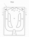
- the fluidic component 1 from figure 4 has (in contrast to the fluidic component 1 from Figures 1 to 3 ) no separators and no outlet expansion.
- the outlet channel 107 extends from the inlets 104a1, 104b1 of the bypass channels 104a, 104b to the outlet port 102.
- Sections (parts) of the boundary wall 5, which extend substantially perpendicularly to the plane of oscillation and limit the outlet channel 107, are designed to be movable.
- the movable sections (parts) of the boundary wall 5 are identified by reference numerals 51a, 51b.
- the movable portions (parts) 51a, 51b are each rotatably supported about a rotation axis Ra, Rb extending substantially perpendicular to the plane of oscillation.
- the movable sections (parts) 51a, 51b can be rotated about the axes of rotation Ra, Rb by means of a device (not shown).
- the movable portions (parts) 51a, 51b are rotatable independently of each other, but may be rotated in unison.
- the axes of rotation Ra, Rb are arranged near the entrances 104a1, 104b1 of the bypass channels 104a, 104b.
- the parts 51a, 51b can each have at least one deformable section to allow rotation of the parts 51a, 51b and deformation of the outlet channel 107.
- the parts 51a, 51b can be designed to be elastically and reversibly deformable, at least in sections. So can in Depending on the mass flow (referred to above as internal force) (or the pressure) of the fluid flow entering the fluidic component, the shape of the at least one deformable section and thus the orientation of the parts 51a, 51b change.
- the parts 51a, 51b can act like a flexure joint depending on the mass flow and can perform a rotational movement while stretching or compressing the respective at least one deformable section.
- the cross-sectional area of the outlet opening 102 can increase or decrease, for example, depending on the specific geometric configuration of the parts 51a, 51b and the specific arrangement of the deformable sections within the parts 51a, 51b. With an increasing inlet pressure, the cross-sectional area of the outlet opening can increase. This counteracts the tendency to produce smaller droplets at higher inlet pressures. In this way it can be achieved that by changing the size of the cross-sectional area of the outlet opening, the resulting droplet sizes are hardly dependent on the admission pressure.
- the volume flow at the outlet opening can be kept almost constant despite a change in the admission pressure.
- the oscillation angle and thus largely also the spray angle can be reduced as the inlet pressure increases.
- the movable portions 51a, 51b in the embodiment of FIG figure 4 can rotate through an angle between two maximum deflection positions, one of which is in figure 4 is shown with a solid line and the other with a broken line.
- the maximum deflection positions are in figure 4 shown as an example.
- the movable sections 51a, 51b can steplessly assume any position between the two maximum deflection positions.
- a rotation changes the orientation of the movable sections 51a, 51b to each other and to the rest of the boundary wall 5.
- the angle ⁇ of the outlet channel 107 changes.
- the width b EX of the outlet opening 102 changes deflection position to the other (shown in phantom) maximum deflection position, the movable sections 51a, 51b are rotated such that (increasing the width b EX of the outlet opening 102) the outlet opening 102 shifts downstream. This also changes (increases) the component length I.
- the oscillation angle of the exiting fluid flow and the possible throughflow can be influenced.
- the volume of the outlet channel 107 changes. The angle between the two maximum deflection positions and the location of the The two maximum deflection positions with respect to the longitudinal axis A can be selected depending on the area of application.
- the boundary wall 5 of the flow chamber 10 is formed by the inner surface of a hollow body, with the cavity of the hollow body forming the flow chamber 10 .
- the boundary wall 5 is connected to the outer surface of the hollow body, which determines the outer appearance of the fluidic component.
- the movable portions 51a, 51b of the boundary wall 5 are connected to corresponding portions of the outer surface of the hollow body and rotatable together with them. Accordingly, the external appearance of the fluidic component also changes when the movable sections 51a, 51b rotate.
- the angle ⁇ between the movable sections 51a, 51b of the boundary wall 5 can be changed, for example, by deforming the inner surface of the hollow body in the area of the outlet channel 107.
- the exiting Fluid jet have a strong or sudden change in acceleration or an almost constant time course without sudden changes in acceleration.
- the fluid distribution can be minimally changed within the spray fan within the oscillation angle.
- an edge-accentuated jet is desirable, i.e. an oscillating jet which, on average over time, stays more in the outer than in the inner area of the spray fan.
- the position of the axes of rotation Ra, Rb, the shape of the inner blocks 11, the shape of the separators 105a, 105b (if present), the type of fluid, the inlet pressure and the volume flow can be selected so that the Fluid flow on the average over time as long as possible to the outlet channel 107 (to the sections 51a, 51b of the boundary wall 5, which are aligned perpendicular to the plane of oscillation and are part of the outlet channel 107) applies.
- the angle ⁇ of the outlet extension 108 (if present) can be set smaller than the free oscillation angle of the fluid stream without the outlet extension 108 .
- the embodiment off figure 5 differs from that one figure 4 in particular by the position of the axes of rotation Ra, Rb. Compared to figure 4 is the distance between the rotation axes Ra, Rb to the outlet opening 102 in figure 5 smaller.
- the volume of the outlet channel 107 and the width b EX of the outlet opening 102 change (compared to figure 4 ) less when the movable portions 51a, 51b are rotated through a defined angle.
- the movable sections 51a, 51b can rotate through an angle between two maximum deflection positions, one of which is in figure 5 is shown with a solid line and the other with a broken line.
- the movable sections 51a, 51b can steplessly assume any position between the two maximum deflection positions.
- the movable sections 51a, 51b are rotated in such a way that (with a change (reduction in sections and enlargement in sections) of the width b ⁇ x of the outlet opening 102) shifts the outlet port 102 upstream.
- the angle between the two maximum deflection positions and the location of the two maximum deflection positions with respect to the longitudinal axis A can be selected depending on the area of application.
- the component length I is also changed (shortened) by the rotation of the movable sections 51a, 51b.
- the volume of the outlet channel 107 changes accordingly.
- the rotation of the movable sections 51a, 51b changes the angle ⁇ and also the width b EX of the outlet opening 102.
- the oscillation angle of the exiting fluid flow, the jet impulse and the pressure loss of the component can be changed.
- the jet impulse can be increased (while the internal pressure remains the same) and the cleaning performance can thereby be increased by focusing the jet force.
- the axes of rotation Ra, Rb can be positioned even closer to the outlet opening 102 in order to minimize the coupling between the change in the angle ⁇ and the outlet width b EX or to avoid a change in the outlet width b EX .
- the movable sections 51a, 51b of the boundary wall 5, which delimit the outlet channel 107 perpendicularly to the oscillation plane, are linearly displaced by means of a displacement device (not shown).
- the movable sections 51a, 51b move in the oscillation plane, respectively along an axis lying in the plane defined by the respective movable portion 51a, 51b.
- the displacement device can have a guide device for each movable section 51a, 51b, in which the movable section 51a, 51b is mounted.
- the guiding devices enclose the angle ⁇ (in the plane of oscillation). In addition, this angle between the guide devices can be variable.
- the movable sections 51a, 51b are slidable between two maximum deflections, one of which is shown with a solid line and the other with a dashed line. The maximum deflection positions are in figure 6 shown as an example.
- the spray behavior such as the oscillation angle
- the spray angle ⁇ By shifting the movable sections 51a, 51b, the spray behavior, such as the oscillation angle, of the fluid flow can be changed. On the one hand, this changes the spray angle ⁇ . If the width b EX of the outlet opening 102 is increased, the oscillation angle is also increased and the spray pulse (with the flow rate remaining the same) is reduced. This is advantageous, for example, for cleaning or wetting (sensitive) surfaces.
- the nozzle size can be changed by changing the width b EX of the outlet opening 102, ie the flow can be regulated with a constant inlet pressure of the fluid.
- a screen-like device can be provided in the area of the outlet opening 102, which extends essentially perpendicularly to the longitudinal axis A and by means of which the cross-sectional area of the outlet opening can be changed without influencing the angle ⁇ .
- the movable sections 51a, 51b can be displaced in the plane of oscillation transversely to the longitudinal axis A in order to change the cross-sectional area of the outlet opening without changing the angle ⁇ .
- the embodiment off figure 7 differs from that one figure 6 particularly in the direction along which the movable portions 51a, 51b are slidable.
- the movable sections 51a, 51b are displaceable along the longitudinal axis A of the fluidic component. With such a shift, the outlet width b ⁇ x and the angle ⁇ remain unchanged. Only the volume of the outlet channel 107 and the component length I of the fluidic component 1 change through the in figure 7 shift shown. It can thus be achieved that the oscillation angle changes only slightly, while the oscillation frequency and the time profile of the emerging fluid flow change significantly.
- one of the maximum deflection positions is shown with a solid line, the other with a dashed line.
- the positions are only examples.
- the two movable sections 51a, 51b can be moved independently of one another. As a result, the oscillation angle and the direction of the exiting fluid flow can be changed. For example, when the movable portion 51a is moved downstream and the movable portion 51b is moved upstream, the direction of the exiting fluid flow changes toward the movable portion 51b moved upstream.
- the two movable sections 51a, 51b can also be moved simultaneously in the same way (direction, speed). This can be achieved, for example, by a telescoping structure of the fluidic component 1 .
- the movable sections 51a, 51b are displaced along the longitudinal axis A with respect to the remaining fluidic component 1 by means of rails.
- the material of the movable sections 51a, 51b (or the other movable elements) can comprise a harder or more wear-resistant material than the rest of the boundary wall 5.
- the fluidic component could 1 can be made of a stainless steel and the movable sections 51a, 51b (or the other movable elements) can be made of a ceramic material.
- the shape of the flow chamber 10 is not achieved by changing the boundary wall 5, but by changing the inner blocks 11a, 11b.
- the two inner blocks 11a, 11b can be changed jointly or independently of one another.
- the two inner blocks can be modified in the same way or differently.
- the change in the inner blocks 11a, 11b consists in a change in the position of the inner blocks 11a, 11b by movement, in particular rotation, of the inner blocks 11a, 11b.
- the rotation can be performed by an unillustrated device. The rotation takes place around the axes of rotation Ra, Rb, extending substantially perpendicular to the plane of oscillation, between two maximum deflection positions. A maximum deflection position is shown as an example with a dashed line, while the other maximum deflection position is shown as an example with a solid line.
- the axes of rotation Ra, Rb are each located in an area of the inner blocks 11a, 11b facing the inlet opening 101 and the main flow channel 103.
- the axes of rotation Ra, Rb are arranged symmetrically with respect to the longitudinal axis A.
- the embodiment off figure 9 differs from that one figure 8 with regard to the position of the axes of rotation Ra, Rb. So the axes of rotation are in figure 9 located further upstream. This changes in the embodiment figure 9 the volume of the main flow channel 103 less than in figure 8 , when the inner blocks 11a, 11b rotate through the same angle.
- the inner blocks 11a, 11b may not be rotated about an axis of rotation, but may be displaced in the plane of oscillation to change the shape of the flow chamber 10.
- the cross-sectional areas of the inlets 104a1, 104b1 and outlets 104a2, 104b2 of the bypass channels can be changed.
- the width of the main flow channel 103 and the secondary flow channels 104a, 104b (in the second section) can be changed.
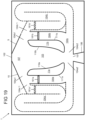
- FIG 10 two different embodiments for changing the inner blocks 11a, 11b are shown.
- the inner block 11a shown on the left is changed by deformation, in particular by deformation of the inwardly pointing surface 110a of the inner block 11a.
- the inner surface 110a faces the main flow channel 103 and extends substantially perpendicular to the plane of oscillation.
- the surface 110a to be deformed can include, for example, a spring material that can assume two stable or metastable states and can be moved back and forth between these two states by the action of an external force (by a device) or by a so-called internal force.
- the so-called internal force can result from the pressure of the fluid stream flowing in the fluidic component.
- the material of the surface 110a to be deformed in terms of material thickness and elasticity
- the material of the surface 110a to be deformed (in terms of material thickness and elasticity) can be selected such that it deforms when there is a pressure change at the inlet opening, at which the flow property in the flow chamber 10 should change , (for low-pressure cleaning) of 5 bar or (for high-pressure cleaning) of 10 bar occurs.
- This pressure data can also be used to select a suitable material for the deformable sections of the parts 51a, 51b mentioned above.
- a so-called intelligent material such as a shape memory alloy can also be used.
- the deformation of the inwardly facing surface 110a of the inner block 11a can be predetermined by additional pivots 110a1 and fixed points 110a2.
- the wall thickness of the inwardly pointing surface 110a of the inner block 11a can be designed with different thicknesses in sections, so that the deformability (resilience) of the material is selectively changed in sections and the surface 110a can then be correspondingly deformed when external forces are applied.
- the inwardly pointing surface 110a of the inner block 11a is preferably shaped in such a way that the main flow channel 103 widens or diverges continuously downstream.
- the inward-facing surface 110a of the inner block 11a is preferably shaped such that the main flow channel 103 first diverges (widens) downstream and converges along the longitudinal axis A at the level of the last third of the inner block 11a (diverges). tapered). (Basically, other shapes can also be assumed in the stable or metastable states.)
- the change in the shape of the main flow channel 103 brought about in this way reduces the change in acceleration of the fluid flow over time, or the change in acceleration assumes an approximately sinusoidal curve.
- the surface 110a pointing inwards is formed by a flat surface or a curved surface with a large radius of curvature.
- the inwardly facing surface 110a can also comprise polygons or splines, in order thus for the most part to form an almost constant angle ⁇ between the inner blocks 11a, 11b. This allows wedges are formed on the inwardly facing surface 110a which protrude into the main flow channel 103.
- the inner block 11a, 11b is constructed in such a way that the fin ray effect or the so-called fin ray effect can be utilized.
- a defined curvature of the inner delimiting wall 110a, 110b of the main flow channel 103 can be achieved with the aid of a displacement or a force effect at one point.
- This fin jet effect can also be used to specifically change the size of the cross-sectional area of the outlet opening, for example by changing the shape of sections 51a, 51b.
- the inner block 11b shown on the right is made up of two parts 11b1, 11b2.
- the dividing line between the two parts 11b1, 11b2 extends essentially from the inlet 104b1 to the outlet 104b2 of the bypass channel 104b.
- the two parts 11b1, 11b2 can be moved (slidably or rotatably) independently of one another in the plane of oscillation. In figure 10 the two parts 11b1, 11b2 are, for example, displaceable.
- the part 11b1 (11b2) facing the main flow channel 103 (side flow channel 104b) By shifting the part 11b1 (11b2) facing the main flow channel 103 (side flow channel 104b), the volume and shape of the main flow channel 103 (side flow channel 104b) can be changed, while the geometry of the side flow channel 104b (main flow channel 103) remains essentially unchanged.
- a channel 112b can arise, which essentially extends from the inlet 104b1 to the outlet 104b2 of the bypass channel 104b.
- a leakage flow between the main flow channel 103 and the secondary flow channel 104b can be avoided by the alignment of this channel 112b.
- the oscillation angle and/or the course over time of the moving fluid jet can be adjusted.
- the deformation of the inner block was described only in relation to the left inner block and the two-part design of the inner block only in relation to the right inner block, both embodiments can be applied to both inner blocks, respectively.
- the shape of the flow chamber 10 is changed by changing the cross-sectional area of the bypass channels 104a, 104b.
- the boundary wall 5 of the flow chamber 10 has a deformable section 52a, 52b downstream of each inlet 104a1, 104a2 of the bypass channels 104a, 104b.
- the deformable sections 52a, 52b are formed symmetrically with respect to the longitudinal axis A. However, only one such deformable section or two deformable sections that are not symmetrical with respect to the longitudinal axis A can also be provided.
- the local deformability of the material of the boundary wall 5 in the sections 52a, 52b can be achieved, for example, by a lower material thickness (compared to the rest of the boundary wall 5) or by a different composition of the material.
- the user can deform the deformable sections 52a, 52b in a targeted manner by means of a device that is not shown.
- the deformed sections 52a, 52b protrude into the bypass channels 104a, 404b transversely to the flow direction of the fluid flow in the bypass channels 104a, 104b.
- a deformed state of the deformable sections 52a, 52b is shown by way of example, not the non-deformed state of the deformable sections 52a, 52b.
- the deformable sections 52a, 52b can also be provided at a different position, for example closer to the outlets 104a2, 104b2 of the bypass channels 104a, 104b.
- the cross-sectional area of the bypass channels 104a, 104b can also be changed by means of a slide that can be moved into the bypass channels 104a, 104b transversely to the direction of flow in the bypass channels 104a, 104b.
- the oscillation frequency can essentially be changed in the case of compressible fluids. (However, if the cross-sectional area of the bypass channels 104a, 104b is reduced too much, the oscillation can come to a standstill.) A fan beam can thereby be generated which extends orthogonally to the original plane of oscillation.
- a fluidic component 1 in which the width b IN of the inlet opening 101 can be changed.
- the wall forming the funnel-shaped projection 106 is designed in several parts.
- the funnel-shaped extension is arranged upstream of the inlet opening 101 .
- the wall of the funnel-shaped extension 106 accordingly has two sections 1061a, 1061b which extend essentially transversely to the plane of oscillation.
- the position of the two sections 1061a, 1061b is in the Oscillation level and transverse to the longitudinal axis A displaceable.
- the width of the funnel-shaped extension 106 and thus of the inlet opening 101 can be changed.
- changing the width b IN of the inlet opening 101 can change the spray characteristics of the exiting fluid flow between a almost punctiform beam and an oscillating fan beam. In this way, for example, the area performance of the fluidic component can be adjusted depending on the task.
- the component length I of the fluidic component 1 is designed to be variable.
- the boundary wall 5 is designed telescopically or like a bellows. This requires the boundary wall 5 to be constructed in at least two parts, one of the two parts being able to be pushed along the longitudinal axis A into the other of the two parts or pulled out of the latter.
- the fluidic component 1 is shown by way of example in two different states, each of which has different component lengths I, I'.
- the part of the boundary wall 5 that can be displaced relative to the other part is shown in dashed lines and in solid lines.
- the inner blocks 11a, 11b are also designed telescopically or bellows-like in order to adapt the length I 11 , I 11 ′ of the inner blocks 11a, 11b according to the component length I, I′ of the fluidic component 1 .
- the length I of the fluidic component 1 and the length I 11 of the inner blocks 11a, 11b can be changed independently of one another or in a coupled manner. According to a further embodiment, either only the length I 11 , I 11 ′ of the inner blocks 11a, 11b or the component length I, I′ of the fluidic component 1 can be changed.
- the temporal jet course of the exiting fluid jet and the oscillation angle can be changed.
- the temporal beam curve approaches a square-wave function. If the component length is further increased when the rectangular function is reached, the oscillation angle decreases until finally a quasi-static hole jet is created.
- the orientation of the inwardly facing surfaces 110a, 110b of the inner blocks 11a, 11b can also change, so that the angle ⁇ changes at the same time. Therewith the change in the oscillation angle can be amplified. This is the case, for example, when the length I 11 of the inner blocks 11a, 11b is changed, the distance between the inner blocks 11a, 11b (in the plane of oscillation and transverse to the longitudinal axis A) remains unchanged.
- figure 14 shows one of the principle of figure 13 similar embodiment.
- the component depth t is variable.
- the cross-sectional area (transverse to the longitudinal axis A) of the main flow channel 103 and the secondary flow channels 104a, 104b can be changed.
- the boundary wall 5 and the inner blocks 11a, 11b are designed in the manner of a telescope or stamp and can be adjusted by means of a device (not shown).
- the oscillation angle can be changed. The oscillation angle is reduced when the component depth t is reduced.
- figure 15 12 shows a fluidic component 1 with two inner blocks 11a, 11b, each of which has a channel 113a, 113b which extends through the inner blocks 11a, 11b.
- Each channel 113a, 113b is aligned in such a way that it fluidly connects the main flow channel 103 to the secondary flow channel 104a, 104b, which is separated from the main flow channel 103 by the respective inner block 11a, 11b.
- the orientation of the channels 113a, 113b is in figure 15 as an example and shown differently for the two inner blocks 11a, 11b.
- the two channels 113a, 113b can be aligned symmetrically (with respect to the longitudinal axis A).
- the channels 113a, 113b can also occupy other positions within the inner blocks 11a, 11b than in FIG figure 15 shown. Also, multiple channels can be formed within an inner block.
- the channels 113a, 113b are designed to be closable, so that a fluid connection between the main flow channel 103 and the secondary flow channels 104a, 104b can be established by means of the channels 113a, 113b.
- the bypass channels 104a, 104b can be designed to be closable.
- the main flow channel 103 can be fluidically connected to the corresponding side flow channel 104a, 104b either via the channel 113a, 113b or via the input 104a1, 104b1 and the output 104a2, 104b2 of the side flow channels 104a, 104b.
- the oscillation frequency of the fluid flow and the temporal course of the emerging fluid jet can be changed.
- the embodiment off figure 16 provides for changing the shape of the flow chamber 10 by deforming the inner blocks 11a, 11b.
- the inner blocks 11a, 11b each have two deformable areas 152a, 153a, 152b, 153b. These are respectively facing the main flow passage 103 and formed in the inward facing surfaces 110a, 110b of the inner blocks 11a, 11b.
- Each of the deformable areas can take two forms. Each shape can correspond to a (meta)stable state of the material, so that when the shape changes, the material switches back and forth between the (meta)stable states.
- the two deformable zones of an inner block are arranged downstream one behind the other.
- the two deformable areas 152a, 153a of one inner block 11a are identical (in terms of shape, deformation and position) to the deformable areas 152b, 153b of the other inner block 11b.
- the two forms that these can assume are shown.
- one of the two shapes is shown with a broken line and the other of the two shapes with a solid line.
- the deformable areas 152a, 152b, 153a, 153b can be deformed individually, with a deformable area of one inner block and the corresponding deformable area of the other inner block preferably being shaped in the same way, so that a total of four combinations are possible.
- Regions 152a, 152b, 153a, 153b are deformable by means of a device operable by the user. The deformation changes the shape of the main flow channel 103, which leads to a change in the oscillation angle of the emerging fluid flow.
- the areas 152a, 153a, 152b, 153b can be moved into or out of the main flow channel 103 in the plane of oscillation by a ram-like movement of a device (not shown).
- An outlet enlargement 108 can additionally be provided downstream of the outlet opening 102 . This is for example in the embodiments from the figures 1 and 17 shown.
- the outlet enlargement 108 preferably has a length l 108 (extension along the longitudinal axis A) which is at least 25% of the outlet width b EX .
- the spray jet is thus guided within the oscillation level and thus leads to an increase in the spray impulse.
- the additional outlet extension 108 is particularly advantageous for cleaning applications.
- the outlet extension comprises two sections 53a, 53b of the boundary wall, which extend substantially perpendicularly to the plane of oscillation. These two sections 53a, 53b can be movable, in particular rotatable about an axis which extends substantially perpendicular to the plane of oscillation.
- the two sections 53a, 53b are rotatable about the axes of rotation Ra, Rb.
- the axes of rotation Ra, Rb are arranged at the transition between the outlet channel 107 and the outlet enlargement 108, that is to say (viewed along the longitudinal axis A) at the level of the outlet opening 102.
- These can also be arranged differently, similar to what is shown in figure 4 or figure 5 is shown as an example.
- the axes of rotation Ra, Rb are located slightly outside of the outlet port 102.
- the axes of rotation Ra, Rb can be located precisely at the upstream end of the two sections 53a, 53b.
- the angle ⁇ between the two sections 53a, 53b of the outlet enlargement can be changed by rotating the two sections 53a, 53b about the axes of rotation Ra, Rb.
- the rotation can be driven by a device not shown.
- Another variant for setting the angle ⁇ is when the axes of rotation Ra, Rb are located in the vicinity of the outlet opening 102, i.e. are displaced along the longitudinal axis A upstream or downstream with respect to the outlet opening 102.
- the shape of the outlet opening 102 is variable.
- the outlet opening 102 has a radius 109, 109′, 109′′, the size of which can be changed. If the radius 109, 109′, 109′′ is changed, the shape of the adjoining sections of the boundary walls of the outlet channel 107 and the Outlet extension 108 and, where appropriate, the angle ⁇ come.
- the outlet opening 102 is shown with a sharp edge as a solid line. Here the radius 109 is equal to zero.
- Alternative shapes of the outlet opening 102 are shown as dashed lines.
- the outlet opening (viewed in the oscillation plane) has a radius of 109 ⁇ on the left and a radius of 109" on the right, which are different in size and each greater than zero degrees.
- a body 190 that can be displaced in the oscillation plane which, by displacement, exerts a force on the material that delimits the outlet opening 102 and the adjacent areas of the outlet channel 107 and the outlet enlargement 108 and is elastically deformable is, can exert and thus bring about a deformation of the elastic material.
- the displacement of the body 190 is in figure 18 indicated by a double arrow.
- FIG 19 shows a further embodiment in which four bypass channels 104a, 104a', 104b, 104b' are formed.
- two side-flow ducts 104a, 104a' or 104b, 104b' form a unit in which the two side-flow ducts are connected in parallel.
- the other bypass channel of the unit is closed at this point in time by means of a partition 181a, 181a', 181b, 181b'.
- the partition walls 181a, 181a', 181b, 181b' can be moved into and out of the bypass channels by means of a device that is not shown.
- the partition walls of a unit can be coupled in this way be that a movement of a dividing wall 181a, 181b into the corresponding bypass duct 104a, 104b is linked to a movement of the other dividing wall 181a', 181b' out of the corresponding other bypass duct 104a', 104b'.
- the fluid only flows through the bypass channel, which is not closed by a partition.
- the two bypass channels 104a, 104a' and 104b, 104b' of a unit have a different shape. By actuating the device, the bypass channel can thus be released and flowed through, which has the shape required to generate the desired jet profile of the fluid flow at the outlet opening.
- each unit is identical and are each aligned mirror-symmetrically with respect to the main flow channel 103 .
- Each unit has a shorter 104a, 104b and a longer 104a', 104b' bypass duct. While the shorter side-flow channel 104a, 104b runs predominantly in a straight line, the longer side-flow channel 104a', 104b' strings together three predominantly straight, parallel sections in a meandering manner. The number of sections can also differ from three.
- Flowable elements 200, 200 ⁇ , 200" are provided, which protrude into the flow chamber 10 transversely to the oscillation plane in the area of the inlet 104a1, 104b1 and the outlet 104b2 of the bypass channels 104a, 104b.
- the arrangement in the area of the inlets 104a1, 104b1 and the outlet 104b2 is only an example insofar as any combination of the inputs 104a1, 104b1 and the outputs 104a2, 104b2 is conceivable.
- FIG 20 different configurations (shape, relative arrangement) of the flow-around elements 200, 200', 200" are shown, whereby these configurations are also only to be understood as examples.
- a flow-around element 200 is shown, which is shown in Oscillation plane has an elliptical cross-section and which is rotatable about an axis which extends substantially perpendicularly to the oscillation plane.
- the rotatability is indicated by the curved double arrow.
- the axis of rotation is here in the center of the element 200, but can also be eccentric.
- other shapes can also be used, preferably those (elongated) shapes which, when rotated, result in a significant change in the shape of the inlet 104a1 of the bypass channel 104a.
- a plurality of elements 200' (here three by way of example) around which a flow can flow are shown, which have a round cross-section (here by way of example) in the oscillation plane and in the oscillation plane are movable.
- a device provided for displacing the elements 200' is in figure 20 not shown. The displaceability is indicated by double arrows.
- a translationally adjustable element 200" is shown, which is sickle-shaped in the oscillation plane (here by way of example).
- the element 200" is attached to a device 201, which is used to change the position and/or the orientation of the Element 200 "is used.
- the position of the adjustable element 200 " can additionally influence the flow in the main flow channel, and thus the spray characteristics of the exiting fluid flow can be adjusted in a targeted manner.
- the elements 200, 200', 200" shown can be moved between two positions or several positions (e.g. intermediate positions between the two positions) or can be moved continuously. The extent of the movement is limited to the elements 200, 200', 200" in remain in the respective inlet or outlet region 104a1, 104b1, 104a2, 104b2 and in particular do not reach the outlet channel 107 or main flow channel 103.
- FIG. 21 and 22 another embodiment is shown.
- figure 22 a sectional view through the fluidic component figure 21 transverse to the plane of oscillation along the line A'-A".
- the fluidic component has two bypass channels 104a, 104b, each of which has an opening 170a, 170b.
- the openings 170a, 170b are here, for example, approximately in the middle between the inlet 104a1, 104b1 and the exit 104a2, 104b2 of each bypass passage 104a, 104b
- the openings 170a, 170b may also be arranged at other positions between the entrance 104a1, 104b1 and the exit 104a2, 104b2 of the bypass passages 104a, 104b
- the two openings 170a, 170b are essentially at the same height in the fluid flow direction (or along the line A ⁇ -A") considered.
- the openings 170a, 170b are each formed in the front wall 12 of the fluidic component.
- a closable connecting channel 170 opens out into the two openings 170a, 170b
- the openings 170a, 170b and the connecting channel 170 have in the embodiment of FIG figures 21 and 22 a rectangular cross section. However, other cross-sectional shapes are also possible.
- the connecting channel 170 can be closed by means of a partition wall 171 which can be moved (transversely to the fluid flow direction) into and out of the connecting channel 170 (by means of rotation or translation).
- the partition wall 171 can be located at any point between the openings 170a, 170b.
- a partition wall 171 can be provided in each case, which already separates the secondary flow channels 104a, 104b from the connecting channel 170 in the region of the openings 170a, 170b.
- the position of the partition wall 170 can be changed by means of a mechanism that is not shown.
- the component depth t of the fluidic component is shown as constant as an example. Alternatively, the component depth t cannot be constant.
- an eccentric can be used instead of the axis of rotation. This makes it possible to reduce the connection between an angle change (e.g. the angle ⁇ or the angle ⁇ ) and a change in distance (e.g. the outlet width b EX or between the ends of the inner blocks 11a, 11b facing the inlet opening) or to change the angle, without changing the distance at the same time.
- an angle change e.g. the angle ⁇ or the angle ⁇
- a change in distance e.g. the outlet width b EX or between the ends of the inner blocks 11a, 11b facing the inlet opening
- the movement of these parts can be coupled or independent of one another and can be simultaneous or staggered in time.
- the speed at which the movement takes place can also be the same or different for the several parts.
Landscapes
- Nozzles (AREA)
- Reciprocating Pumps (AREA)
Description
- Die Erfindung betrifft ein fluidisches Bauteil nach dem Oberbegriff des Anspruchs 1 und ein Fluidverteilungsgerät, das ein solches fluidisches Bauteil umfasst.
- Bei Fluidverteilungsgeräten wie beispielsweise Reinigungsgeräten ist es wünschenswert, Fluidstrahlen mit unterschiedlichen Sprühcharakteristiken erzeugen zu können, um den Anforderungen in unterschiedlichen Einsatzbereichen gerecht zu werden. So besteht beispielsweise Bedarf an einem Gerät, das wahlweise Rund- und Fächerstrahlen erzeugen kann. So können stark festsitzende Verschmutzungen mit dem hohen Strahlimpuls eines Rundstrahls punktartig und sensible Oberflächen mit dem örtlich geringeren Strahlimpuls eines Fächerstrahls (das heißt mit einer geringeren Flächenleistung) flächig behandelt und gereinigt werden. Ein Fächerstrahl beziehungsweise ein Fluidstrahl mit großer räumlicher Verteilung des Fluids ist gut zum Abspülen geeignet.
- Zur Erzeugung eines Fluidstrahls mit unterschiedlichen Sprühcharakteristiken sind aus dem Stand der Technik Düsensysteme bekannt, bei denen zum Beispiel mittels eines Schiebers oder eines Drehmechanismus zwischen einer Mehrzahl von Düsen mit jeweils unterschiedlichen Sprühcharakteristiken hin und her geschaltet wird. Hierbei weist jede Düse für sich eine definierte und unveränderliche Sprühcharakteristik auf und gibt dem Fluidstrahl eine Strahlform fest vor.
- Diese Düsensysteme erzeugen quasistatische beziehungsweise statische und nicht oszillierende Fluidstrahlen. Zur Erzeugung eines sich bewegenden Fluidstrahls sind aus dem Stand der Technik Düsen bekannt, die mittels einer Kinematik beziehungsweise einer (beweglichen) Vorrichtung in Bewegung versetzt werden. Die Kinematik beziehungsweise (bewegliche) Vorrichtung umfasst bewegliche Komponenten, die hohem Verschleiß ausgesetzt sind. Die mit der Herstellung und Wartung verbundenen Kosten sind entsprechend hoch. Zudem ist aufgrund der beweglichen Komponenten insgesamt ein relativ großer Bauraum erforderlich.
- Zur Erzeugung eines beweglichen Fluidstroms (oder Fluidstrahls) sind ferner fluidische Bauteile bekannt, die einen in einer Ebene oszillierenden Fluidstrahl erzeugen. Die fluidischen Bauteile umfassen keine beweglichen Komponenten, die der Erzeugung eines beweglichen Fluidstroms dienen. Dadurch weisen sie im Vergleich zu den Düsen mit beweglichen Komponenten nicht die aus den beweglichen Komponenten resultierenden Nachteile auf.
- Das fluidische Bauteil ist zur Erzeugung eines sich bewegenden, oszillierenden oder pulsierenden Fluidstrahls vorgesehen. Beispiele für Fluidfließmuster eines oszillierenden Strahls sind sinusförmige Strahloszillationen, rechteckige, sägezahnförmige oder dreieckige Strahlverläufe, räumliche oder zeitliche Strahlpulsationen und Schaltvorgänge. Solche Fluidstrahlen werden eingesetzt, um beispielsweise einen Fluidstrahl (oder Fluidstrom) auf einem Zielgebiet gleichmäßig zu verteilen. Der Fluidstrom kann ein Flüssigkeitsstrom, ein Gasstrom, ein Mehrphasenstrom (zum Beispiel Nassdampf) oder auch ein partikelbehaftetes Fluid sein.
- Die aus dem Stand der Technik bekannten fluidischen Bauteile zur Erzeugung eines sich bewegenden Fluidstroms weisen in der Regel eine feste Sprüheigenschaft bei gleichbleibenden Volumenstrom und/oder Eingangsdruck des Fluids auf. In
US 6,497,375 B1 undWO 02/07893 A1 US 2006/0065765 A1 ist eine Vorrichtung bekannt, die eine Mehrzahl von fluidischen Bauteilen mit jeweils unterschiedlichen Sprüheigenschaften umfasst, von denen wahlweise ein fluidisches Bauteil in den Fluidstrahl gedreht werden und somit (je nach Wahl des fluidischen Bauteils) ein Fluidstrom mit unterschiedlichen Sprüheigenschaften erzeugt werden kann. Eine solche Vorrichtung erfordert insgesamt einen relativ großen Bauraum. Zudem kann die Sprühcharakteristik des austretenden Fluidstroms nur zwischen einer vorgegebenen Anzahl von Möglichkeiten variiert werden. -
US 4,508,267 A offenbart ein weiteres fluidisches Bauteil aus dem Stand der Technik. - Der vorliegenden Erfindung liegt die Aufgabe zugrunde, eine Vorrichtung zu schaffen, die ausgebildet ist, einen sich bewegenden Fluidstrahl zu erzeugen, dessen Sprühcharakteristik vor dem Betrieb einstellbar beziehungsweise während des Betriebes veränderbar ist, wobei die Vorrichtung eine hohe Ausfallsicherheit und einen entsprechend geringen Wartungsaufwand aufweist.
- Diese Aufgabe wird erfindungsgemäß durch ein fluidisches Bauteil mit den Merkmalen des Anspruchs 1 gelöst. Ausgestaltungen der Erfindung sind in den Unteransprüchen angegeben.
- Danach umfasst das fluidisches Bauteil eine Strömungskammer, die von einem Fluidstrom durchströmbar ist, der durch eine Einlassöffnung der Strömungskammer in die Strömungskammer eintritt und durch eine Auslassöffnung der Strömungskammer aus der Strömungskammer austritt. Vorzugsweise sind die Einlassöffnung und die Auslassöffnung auf sich gegenüberliegenden Seiten der Strömungskammer angeordnet. In der Strömungskammer ist mindestens ein Mittel zur Ausbildung einer Oszillation des Fluidstroms an der Auslassöffnung vorgesehen. Das Mittel zur Ausbildung einer Oszillation kann beispielsweise mindestens ein Nebenstromkanal sein. Alternativ können auch andere Mittel zur Ausbildung einer Oszillation des Fluidstroms vorgesehen sein.
- Das fluidische Bauteil zeichnet sich dadurch aus, dass die Strömungskammer eine veränderbare Form aufweist. Zur Veränderung der Form der Strömungskammer kann insbesondere eine Vorrichtung vorgesehen sein, die gezielt auf das fluidische Bauteil einwirkt und somit eine Veränderung der Form der Strömungskammer herbeiführt. Die Formveränderung der Strömungskammer ist dabei vorzugsweise reversibel. Das heißt, dass die Vorrichtung eine Formveränderung herbeiführen und auch wieder rückgängig machen kann. Zur Veränderung der Form der Strömungskammer können verschiedenen Parameter des fluidischen Bauteils (beziehungsweise Teile davon), wie beispielsweise die Form oder das Volumen verändert werden. Hierdurch kann eine Veränderung der Sprühcharakteristik des austretenden Fluidstroms herbeigeführt werden, ohne die Parameter des das fluidische Bauteil durchströmenden Fluids, wie beispielsweise die Art des Fluids, den Eingangsdruck des Fluids, die Eingangsgeschwindigkeit des Fluids und den Volumendurchfluss, zu verändern. Die Veränderung der Form kann stufenlos (oder wahlweise auch in Stufen) erfolgen, so dass sich entsprechend auch die Sprühcharakteristik des austretenden Fluidstroms stufenlos (in Stufen) ändert und somit gezielt an eine konkrete Anwendung angepasst werden kann. Die Sprühcharakteristik kann sich insbesondere auf den Sprühwinkel beziehen, der mittels des erfindungsgemäßen fluidischen Bauteils einstellbar ist. So kann der austretende Fluidstrahl zwischen einem Punktstrahl und einem Fächerstrahl moduliert werden. Das erfindungsgemäße fluidische Bauteil kann zur Erzeugung eines gerichteten Fluidstrahls mit verstellbarer Sprühcharakteristik für die gezielte Benetzung, Betropfung oder Überstreichung einer Oberfläche eingesetzt werden. Da mittels des erfindungsgemäßen fluidischen Bauteils der austretende Fluidstrom einerseits eine Oszillationsbewegung ausführt und andererseits hinsichtlich seiner Sprüheigenschaften verstellt werden kann, kann die Reinigungs-, die Oberflächenbenetzungs- oder die Oberflächenbearbeitungsleistung massiv erhöht werden. Da zur Ausbildung der Oszillation keine beweglichen Komponenten eingesetzt werden, kann zudem die Ausfallwahrscheinlichkeit reduziert werden. Durch Änderung der Sprühcharakteristik des austretenden Fluidstroms kann das fluidische Bauteil an unterschiedliche Reinigungsanforderungen angepasst werden. Damit ist das erfindungsgemäße fluidische Bauteil für die Hoch-, die Mittel-, die Niederdruckreinigung, sowie für die Oberflächenbearbeitung und für die Oberflächenbeschichtung interessant. Die Veränderung der Form der Strömungskammer kann vor Inbetriebnahme oder auch während des Betriebes des fluidischen Bauteils, das heißt während das fluidische Bauteil von einem Fluid durchströmt wird, erfolgen.
- Das Fluid, das durch die Einlassöffnung in die Strömungskammer eintritt, kann mit einem Druck von 0,001 bis 6000 bar (gegenüber dem Umgebungsdruck) beaufschlagt sein. Vorzugsweise kann der Druck zwischen 0,005 und 1800 bar liegen. Insbesondere bevorzugt ist ein Druckbereich zwischen 0,05 und 1100 bar. Für einige Anwendungen, sogenannte Niederdruckanwendungen, wie beispielsweise für Waschmaschinen, Geschirrspüler und Fluidverteilungsvorrichtungen (Beregnungsgeräte, Handbrausen oder Reinigungsanlangen), ist ein Eingangsdruck von 0,01 bar bis 12 bar über dem Umgebungsdruck vorteilhaft. Für Mitteldruckanwendungen, wie z.B. Hochdruckreinigungsgeräte mit geringer Leistung, oder Küchengeräte mit integrierten Reinigungsgeräten liegt der Eingangsdruck vorzugsweise zwischen 6 bar und 120 bar über dem Umgebungsdruck. Bei Hochdruckanwendungen kann der Eingangsdruck über 40 bar betragen. Die Oszillationsfrequenz des aus dem fluidischen Bauteil austretenden oszillierenden Fluidstroms kann zwischen 0,25 Hz und 40 kHz liegen. Ein bevorzugter Frequenzbereich liegt zwischen 3 Hz und 600 Hz.
- Das Fluid kann ein gasförmiges, flüssiges oder mehrphasiges, fließfähiges Medium sein, welches auch mit Partikeln behaftet sein kann. Wenn das Fluid eine Flüssigkeit (zum Beispiel Wasser) ist, ist es vorteilhaft, die Geometrie des fluidischen Bauteils so zu wählen, dass innerhalb des fluidischen Bauteils (stromaufwärts der Auslassöffnung) ein im Vergleich zu dem an der Auslassöffnung erfolgenden Druckabbau geringer Druckabbau erfolgt. Die geometrischen Parameter (Form, Größe, Anzahl und Form der Nebenstromkanäle, (relative) Größe der Ein- und Auslassöffnung) des fluidischen Bauteils sind in diesem Fall so gewählt, dass der Druck, mit dem der Fluidstrom beaufschlagt ist, wenn er über die Einlassöffnung in das fluidische Bauteil eintritt, im Wesentlichen an der Auslassöffnung abgebaut wird. Wenn das Fluid Wasserdampf ist, können die Parameter so gewählt werden, dass der Druck, mit dem der Fluidstrom beaufschlagt ist, wenn er über die Einlassöffnung in das fluidische Bauteil eintritt, bereits vor (stromaufwärts) der Auslassöffnung abgebaut wird.
- Gemäß einer Ausführungsform wird die Strömungskammer durch eine Begrenzungswand begrenzt. Dabei muss die Begrenzungswand nicht die äußere Erscheinungsform des fluidischen Bauteils bilden. Die Begrenzungswand kann durch die Innenoberfläche eines Hohlkörpers gebildet sein, wobei der Hohlraum des Hohlkörpers die Strömungskammer bildet. Die äußere Erscheinungsform des fluidischen Bauteils wird dann von der Außenoberfläche des Hohlkörpers definiert. Die Außenoberfläche des Hohlkörpers kann insbesondere im Wesentlichen quaderförmig sein und Unterbrechungen für die Einlassöffnung und die Auslassöffnung aufweisen.
- Die Strömungskammer weist einen Hauptstromkanal, der die Einlassöffnung und die Auslassöffnung miteinander verbindet, und mindestens einen Nebenstromkanal als Mittel zur Ausbildung einer Oszillation des Fluidstroms an der Auslassöffnung auf.
- Die Richtung von der Einlassöffnung zur Auslassöffnung kann dabei als Hauptstromrichtung des Fluidstroms angesehen werden. Dabei sind der Hauptstromkanal und der mindestens eine Nebenstromkanal durch mindestens einen inneren Block voneinander getrennt, so dass der Hauptstromkanal, der mindestens eine innere Block und der mindestens eine Nebenstromkanal im Wesentlichen in einer Ebene angeordnet sind. Der austretende Fluidstrom oszilliert dann in einer Oszillationsebene, die der Ebene entspricht, die durch den Hauptstromkanal, den mindestens einen inneren Block und den mindestens einen Nebenstromkanal definiert ist. Insbesondere kann die Strömungskammer zwei Nebenstromkanäle aufweisen, die mit dem Hauptstromkanal in einer Ebene liegen, wobei der Hauptstromkanal (quer zur Hauptstromrichtung betrachtet) zwischen den beiden Nebenstromkanälen liegt. In diesem Fall ist jeder Nebenstromkanal durch mindestens einen inneren Block von dem Hauptstromkanal getrennt. Die Nebenstromkanäle können jeweils einen Eingang und einen Ausgang aufweisen, über die sie mit dem Hauptstromkanal fluidisch verbunden sind.
- Um die Form der Strömungskammer verändern zu können, kann die Begrenzungswand gemäß einer Ausführungsform mindestens einen Abschnitt aufweisen, der verformbar ist. Dazu kann der mindestens eine Abschnitt im Vergleich zu der restlichen Begrenzungswand andere Materialeigenschaften aufweisen, wie zum Beispiel Materialstärke oder Dehnbarkeit (Elastizität). Unter gezielter Einwirkung einer äußeren Kraft kann dann der mindestens eine verformbare Abschnitt der Begrenzungswand verformt werden.
- Unter einer gezielten Einwirkung einer äußeren Kraft ist insbesondere nicht der Druck des das fluidische Bauteil durchströmenden Fluids zu verstehen. Vielmehr kann eine Vorrichtung zur Ausübung der äußeren Kraft vorgesehen sein, die durch einen Benutzer betätigbar ist. Dies gilt ebenso für die anderen Ausführungsformen.
- Alternativ zu der oben erwähnten gezielten Einwirkung einer äußeren Kraft kann eine innere Kraft, die im Wesentlichen aus dem Druck des das fluidische Bauteil durchströmenden Fluids resultiert, genutzt werden, um den mindestens einen verformbaren (z. B. elastischen) Abschnitt der Begrenzungswand gezielt zu verformen. Dabei kann der mindestens eine verformbare Abschnitt derart ausgebildet sein, dass er durch Einwirkung der inneren Kraft reversibel verformbar ist, das heißt bei einer Erhöhung des Massenstroms an der Einlassöffnung (des Eingangsdrucks) von einer ersten in eine zweite Konfiguration übergeht und bei einem Abfall des Massenstroms an der Einlassöffnung (des Eingangsdrucks) von der zweiten in die erste Konfiguration zurückkehrt. Auch ist der Übergang zwischen mehr als zwei Konfigurationen oder ein stufenloser Übergang denkbar. Insbesondere kann durch die vom Massenstrom abhängige Verformung des mindestens einen verformbaren Abschnitts der Begrenzungswand und in Abhängigkeit von der konkreten Position des mindestens einen verformbaren Abschnitts in der Strömungskammer und insbesondere an der Auslassöffnung ein nahezu konstanter Druck beziehungsweise Volumenstrom eingestellt werden. Dadurch kann das fluidische Bauteil zu einem sogenannten sich selbst regelnden System werden, das trotz variierendem Vordruck beziehungsweise Fluideingangsdruck an der Auslassöffnung einen nahezu konstant hohen Volumenstrom aufweist und ein nahezu gleichbleibendes Tropfenspektrum erzeugt. Dabei kann bei steigendem (sinkendem) Druck an der Einlassöffnung der Sprühwinkel des austretenden Fluidstroms nahezu konstant bleiben oder sich verkleinern (vergrößern). Beispielsweise kann der mindestens eine verformbare Abschnitt der Begrenzungswand als eine die Auslassöffnung (quer zur Fluidstromrichtung) begrenzende elastisch verformbare Wand ausgebildet sein, die sich bei Änderung des Fluiddruckes an der Auslassöffnung verformt und dabei die Querschnittsfläche der Auslassöffnung soweit ändert, dass die resultierenden Tropfengrößen des austretenden Fluidstroms kaum vom Vordruck abhängig sind, und dass der Druck an der Auslassöffnung im Wesentlichen auf das zuvor herrschende Niveau zurückkehrt beziehungsweise auf diesem Niveau verbleibt. Mit anderen Worten, bei dem sich selbst regelnden System sinkt der Sauter-Durchmesser der Tropfen des austretenden Fluidstroms im Vergleich zu einem nahezu starren, nicht veränderbaren System mit ansteigendem Eingangsdruck weniger stark, oder bleibt trotz ansteigendem Eingangsdruck nahezu stabil.
- Das Material des mindestens einen verformbaren Abschnitts der Begrenzungswand ist dabei derart zu wählen, dass es sich nicht bei einem beliebigen Druck des das fluidische Bauteil durchströmenden Fluids, das die sogenannte innere Kraft auf den mindestens einen verformbaren Abschnitt ausübt, verformt, sondern nur in einem vorbestimmten Druckbereich beziehungsweise Druckänderungsbereich. Das erfindungsgemäße fluidische Bauteil ist für verschiedene Anwendungen einsetzbar, in denen einerseits die Abmessungen des fluidischen Bauteils und andererseits der an der Auslassöffnung bereitzustellende Volumenstrom mehr oder weniger stark variieren können. Bei der Abmessung spielt insbesondere die engste durchströmbare Stelle des fluidischen Bauteils eine Rolle. Unter der engsten durchströmbaren Stelle eines fluidischen Bauteils ist in Fluidstromrichtung betrachtet die Stelle (außerhalb der Nebenstromkanäle) zu verstehen, an der das fluidische Bauteil seine kleinste Querschnittsfläche aufweist, die sich im Wesentlichen quer zur Fluidstromrichtung erstreckt. Die engste Stelle kann dabei durch die Einlassöffnung, die Auslassöffnung oder durch eine Stelle in dem Hauptstromkanal gebildet werden, an der der Abstand (quer zur Fluidstromrichtung) zwischen den inneren Blöcken am geringsten ist.
- Fluidische Bauteile für Reinigungs-, Benetzungs-, Beschichtungs- oder Spülanwendungen können an ihrer engsten Stelle eine Querschnittsfläche von 0,005 mm2 bis zu 200 mm2 aufweisen. Für Spezialanwendungen mit geringem Durchfluss kann die engste Stelle eine Querschnittsfläche von 0,005 mm2 bis 5 mm2 aufweisen. Im Agrarbereich und für Beregnungsaufgaben kann das fluidische Bauteil eine engste Stelle mit einer Querschnittsfläche von 0,01 mm2 bis ca. 30 mm2 aufweisen. Typische Eingangsdrücke für das Fluid in diesem Anwendungsbereich (Querschnittsfläche von 0,01 mm2 bis ca. 30 mm2) sind 0,25 bar bis 16 bar über dem Umgebungsdruck. Für Anwendungen der fluidischen Bauteile in der Niederdruckreinigung sind Eingangsdrücke von 1 bar bis 60 bar über dem Umgebungsdruck üblich, wobei die engste Stelle eine Querschnittsfläche von 0,3 mm2 bis zu 200 mm2 haben kann. Für Anwendungen der fluidischen Bauteile in der Hochdruckreinigung können Drücke von 40 bar bis ca. 1500 bar über dem Umgebungsdruck eingesetzt werden, wobei die engste Stelle eine Querschnittsfläche von 0,5 mm2 bis 180 mm2 annehmen kann.
- In einem sich selbst regelnden Düsensystem, das trotz Änderungen des Eingangsdrucks (des an der Einlassöffnung in das fluidische Bauteil eintretenden Fluidstroms) an der Auslassöffnung einen nahezu konstanten Volumenstrom bereitstellt, kann der mindestens eine verformbare Abschnitt der Begrenzungswand derart angeordnet sein, dass er die Einlassöffnung und/oder die Auslassöffnung begrenzt oder dass er eine Bewegung eines bewegbaren Teils der Begrenzungswand ermöglicht, wobei die Bewegung zu einer Änderung der Querschnittsfläche der Einlassöffnung beziehungsweise der Auslassöffnung führt. So kann durch die konkrete Ausrichtung des bewegbaren Teils der Begrenzungswand bestimmt werden, ob die Bewegung des bewegbaren Teils der Begrenzungswand aufgrund einer Verformung (Dehnung infolge eines Anstiegs des Eingangsdrucks) des mindestens einen verformbaren Abschnitts die Querschnittsfläche vergrößert oder verkleinert. Zusätzlich oder alternativ können die inneren Blöcke mindestens einen verformbaren Abschnitt an oder nahe der Stelle in dem Hauptstromkanal aufweisen, an der der Abstand (quer zur Fluidstromrichtung) zwischen den inneren Blöcken am geringsten ist, so dass eine Änderung der Querschnittsfläche dieser Stelle in dem Hauptstromkanal möglich ist. Als Material für diesen mindestens einen verformbaren Abschnitt (der Begrenzungswand beziehungsweise der inneren Blöcke) kann ein Material verwendet werden, das sich entsprechend der Druckänderungen dehnen beziehungsweise stauchen kann, um die Größe der Querschnittsflächen zu ändern.
- Für ein fluidisches Bauteil mit einem Widerstandsbeiwert von 0,89 und einer engsten Stelle (Einlassöffnung, Auslassöffnung oder Stelle in dem Hauptstromkanal) mit einer Querschnittsfläche von ca. 0,75 mm2 sollte das Material derart verformbar sein, dass sich bei einem Druckabfall um den Faktor 100 diese Querschnittsfläche um den Faktor 10 vergrößert. Steigt im Gegenzug in diesem fluidischen Bauteil der Druck an der Einlassöffnung um den Faktor 100 (beispielsweise von 3 bar auf 300 bar), sollte sich diese Querschnittsfläche um einen Faktor 10 (von ca. 0,75 mm2 auf ca. 0,075 mm2) reduzieren. Das Ausmaß der Veränderung der Querschnittsfläche ist insbesondere vom (teilweise druckabhängigen) Widerstandsbeiwert des fluidischen Bauteils abhängig.
- Ein sich selbst regelndes Düsensystem kann auch derart gestaltet sein, dass bei variierenden Volumenströmen an der engsten Stelle (Einlassöffnung, Auslassöffnung oder Stelle in dem Hauptstromkanal), die von variierenden Eingangsdrücken herrühren, innerhalb des fluidischen Bauteils der gleiche Druckabbau erfolgt. Dazu sollte sich bei steigendem Volumenstrom die Querschnittsfläche der engsten Stelle vergrößern. Beispielsweise vergrößert sich die Querschnittsfläche (1 mm2) um ca. 14%, wenn an der engsten Stelle der Volumenstrom von 1,4 l/min auf 1,6 l/min steigt.
- Zur Änderung der Größe der Querschnittsfläche der engsten Stelle können beispielsweise geometrische Nichtlinearitäten, elastisch verformbare Abschnitte der Begrenzungswand beziehungsweise der inneren Blöcke (ähnlich wie bei Festkörpergelenken) oder der sogenannte Fin Ray Effekt ausgenutzt werden. Durch die Erhöhung des Eingangsdruckes kann so eine erhöhte (innere) Kraft auf die Begrenzungswand und die inneren Blöcke einwirken. Diese Kraft sorgt für eine reversible (elastische) Verformung eines Abschnitts der Wand, die je nach Wirkprinzip dann zu einer Verformung eines anderen Abschnittes der Wand sorgt. Eine Änderung des Durchflusses kann ferner durch eine Anpassung des Druckverlustbeiwertes erreicht werden. Zur Erhöhung der Querschnittsfläche der engsten Stelle kann der die engste Stelle begrenzende Wandabschnitt so ausgebildet sein, dass dieser in Abhängigkeit des ansteigenden Druckes, zum Beispiel durch die Elastizität (Nachgiebigkeit) des Materials, diesen Wandabschnitt elastisch beziehungsweise reversibel verformt.
- Gemäß einer weiteren Ausführungsform kann der mindestens eine verformbare Abschnitt der Begrenzungswand abschnittsweise den mindestens einen Nebenstromkanal bilden. Bei zwei Nebenstromkanälen können zwei solcher verformbarer Abschnitte vorgesehen sein, so dass beide Nebenstromkanäle gleichartig aufgebaut sein können. Der verformbare Abschnitt kann derart ausgebildet sein, dass durch Verformung des Abschnitts die Querschnittsfläche des/der Nebenstromkanals/Nebenstromkanäle lokal veränderbar (verringerbar) ist. Hierdurch kann bei kompressiblen Fluiden insbesondere die Oszillationsfrequenz des austretenden Fluidstroms verändert werden. Dadurch kann ferner ein Fächerstrahl erzeugt werden, der im Wesentlichen orthogonal zu der Oszillationsebene ausgerichtet ist. Als Alternative zur Verformung der Begrenzungswand im Bereich des Nebenstromkanals kann die Querschnittsfläche des Nebenstromkanals mittels eines Schiebers verändert werden, der gezielt in den Nebenstromkanal eingebracht werden kann. Die Querschnittsveränderung kann auch durch einen Bolzen oder eine Gewindestange erzielt werden, die in den Nebenstromkanal reingedreht werden können.
- Ferner ist es möglich, dass die Begrenzungswand mindestens zwei Teile umfasst, wobei eines der beiden Teile gegenüber dem anderen der beiden Teile beweglich ist. Die Bewegung kann dabei eine Verschiebung oder eine Rotation sein. Dabei kann die Rotationsachse insbesondere senkrecht zu der Oszillationsebene ausgerichtet sein.
- Jedoch kann der Winkel zwischen der Oszillationsebene und der Rotationsachse auch von 90° abweichen. Die Verschiebung kann insbesondere in der Oszillationsebene erfolgen. Jedoch ist eine Verschiebung, die in einem Winkel zu der Oszillationsebene erfolgt (zum Beispiel 90°) denkbar.
- Gemäß einer Ausführungsform weist die Strömungskammer (unmittelbar) stromaufwärts der Auslassöffnung einen Auslasskanal auf. An seinem stromabwärtigen Ende mündet der Auslasskanal in die Auslassöffnung. Insbesondere kann der Auslasskanal obstruktionsfrei ausgebildet sein, das heißt, dass in dem Auslasskanal keine den Fluidstrom behindernde oder beeinflussende Elemente angeordnet sind. In der Oszillationsebene betrachtet verjüngt sich der Auslasskanal entlang der Hauptstromrichtung stromabwärts. Zur Ausbildung des Auslasskanals erstrecken sich zwei Abschnitte der Begrenzungswand oberhalb und unterhalb der Oszillationsebene im Wesentlichen parallel zur Oszillationsebene. Diese beiden Abschnitte sind durch weitere zwei Abschnitte der Begrenzungswand miteinander verbunden, die sich im Wesentlichen senkrecht zu der Oszillationsebene erstrecken und in der Oszillationsebene einen Winkel miteinander einschließen. Die Abschnitte der Begrenzungswand, die den Auslasskanal bilden können zusammen einstückig ausgebildet sein. Auch kann der Auslasskanal einstückig mit der restlichen Begrenzungswand, die die restliche Strömungskammer bildet, ausgebildet sein. Die Auslassöffnung stellt dabei eine Unterbrechung der Begrenzungswand dar.
- Jedoch können die zwei Abschnitte der Begrenzungswand, die sich im Wesentlichen senkrecht zu der Oszillationsebene erstrecken und Teil des Auslasskanals sind, als zwei bewegliche Teile (Abschnitte) der Begrenzungswand ausgebildet sein, die gegenüber einem dritten Teil der Begrenzungswand (dem Rest des Auslasskanals, der übrigen Strömungskammer oder dem Rest der Begrenzungswand) beweglich sind.
- Diese zwei beweglichen Teile der Begrenzungswand können gegenüber dem dritten Teil der Begrenzungswand drehbar sein. Dabei kann jedes der beiden beweglichen Teile unabhängig von dem anderen der beiden beweglichen Teile gegenüber dem dritten Teil der Begrenzungswand drehbar sein. Die Rotationsachse(n) kann/können sich dabei im Wesentlichen senkrecht zu der Oszillationsebene erstrecken. Durch die Drehung dieser beiden beweglichen Teile der Begrenzungswand kann der Winkel zwischen den beiden beweglichen Teilen der Begrenzungswand in der Oszillationsebene verändert werden. Das kann zu einer Veränderung des Oszillationswinkels des austretenden Fluidstroms führen. Je nach Lage der Rotationsachsen (insbesondere deren Abstand zu der Auslassöffnung (in der Oszillationsebene betrachtet)) kann durch die Rotation der beiden beweglichen Teile der Begrenzungswand auch die Breite der Auslassöffnung variiert werden. Dabei ist die Breite der Auslassöffnung die Ausdehnung der Auslassöffnung senkrecht zu der Hauptstromrichtung innerhalb der Oszillationsebene. Je weiter die Rotationsachsen von der Auslassöffnung entfernt sind, umso stärker ändert sich bei einer Rotation der beiden beweglichen Teile der Begrenzungswand auch die Breite der Auslassöffnung. Eine Veränderung der Breite der Auslassöffnung kann zu einer Änderung des Strahlimpulses und des Druckverlusts an der Auslassöffnung führen. Durch eine Verringerung der Auslassbreite kann der Strahlimpuls bei gleichbleibendem Innendruck erhöht werden, was zu einer Steigerung der Reinigungsleistung durch die Fokussierung der Strahlkraft führen kann. Um die Kopplung zwischen der Änderung des Winkels und der Auslassbreite zu minimieren, können die Rotationsachsen möglichst nahe der Auslassöffnung vorgesehen sein. Um vorrangig den Winkel zwischen den beiden beweglichen Teilen der Begrenzungswand zu ändern, ohne gleichzeitig die Auslassbreite zu beeinflussen, kann anstelle einer Rotationsachse ein Exzenter vorgesehen sein. Im Extremfall ist es möglich, die Auslassbreite konstant zu halten, während der besagte Winkel verändert wird.
- Diese zwei beweglichen Teile der Begrenzungswand können gegenüber dem dritten Teil der Begrenzungswand auch verschiebbar sein. Die Verschiebung kann insbesondere in der Oszillationsebene erfolgen. Die Verschiebung kann dabei so erfolgen, dass die Auslassbreite, nicht jedoch der Winkel zwischen den beiden beweglichen Teilen der Begrenzungswand verändert wird. Beispielsweise kann die Verschiebung entlang der Breite der Auslassöffnung oder entlang jener Achsen erfolgen, in denen sich die Ebenen, die durch die zwei beweglichen Teile der Begrenzungswand aufgespannt werden, und die Oszillationsebene schneiden. Im letzteren Fall ändert sich die Breite der Auslassöffnung, ohne die Querschnittsfläche des Nebenstromkanals am Eingang des Nebenstromkanals zu verändern. In beiden Fällen kann die Breite des austretenden Fluidstrahls verändert werden. Gemäß einer vorteilhaften Ausführungsform ist die Breite der Auslassöffnung bis annähernd zum Wert Null veränderbar. Alternativ kann zwecks Änderung der Auslassbreite eine blendenartige Vorrichtung vorgesehen sein, die im Bereich der Auslassöffnung angeordnet ist und sich im Wesentlichen quer zur Hauptstromrichtung des Fluidstroms erstreckt. Mittels einer solchen Blende kann die Auslassöffnung verändert, insbesondere verkleinert werden. Ferner kann eine Verschiebung dieser zwei beweglichen Teile der Begrenzungswand entlang der Hauptstromrichtung in Richtung der Einlassöffnung erfolgen. Dabei kann die Querschnittsfläche des Eingangs des mindestens einen Nebenstromkanals reduziert werden. Durch diese Maßnahme kann der Oszillationsmechanismus verringert werden beziehungsweise zum Erliegen gebracht werden, so dass der austretende Fluidstrahl zwischen einem oszillierenden Fluidstrahl und einem kompakten geraden Fluidstrahl (beziehungsweise einem Fluidstrahl ähnlich einer Lochdüse) variiert werden kann.
- Zudem ist denkbar, dass die Verschiebung entlang der Hauptstromrichtung des Fluidstroms von der Einlassöffnung weg erfolgt. Hierbei ändern sich die Breite der Auslassöffnung und der Winkel zwischen den beiden separaten Teilen der Begrenzungswand, die Teil des Auslasskanals sind, nicht, jedoch das Volumen des Auslasskanals. Das kann dazu führen, dass sich der Oszillationswinkel nur gering verändert, während sich die Oszillationsfrequenz und der zeitliche Verlauf des austretenden Fluidstrahls stärker verändern.
- Um die zwei beweglichen Teile der Begrenzungswand gegenüber dem dritten Teil der Begrenzungswand bewegen (drehen oder verschieben) zu können, kann eine Vorrichtung vorgesehen sein, die durch einen Benutzer betätigbar ist. Die Bewegung der beiden separaten Teile kann insbesondere unabhängig voneinander erfolgen. So kann der Winkel, unter dem der Fluidstrom aus dem fluidischen Bauteil austritt, verändert werden. Beispielsweise kann eines der beiden Teile stromabwärts und das andere der beiden Teile stromaufwärts bewegt werden. In der Folge, wird der Winkel, unter dem der Fluidstrom aus dem fluidischen Bauteil austritt, in Richtung des stromaufwärts bewegten Teils abgelenkt.
- Gemäß einer vorteilhaften Ausführungsform ist die Begrenzungswand, die den Auslasskanal bildet, aus einem anderen, nämlich einem härteren beziehungsweise verschleißfesteren Werkstoff gefertigt als die restliche Begrenzungswand. So kann die Begrenzungswand, die den Auslasskanal bildet, aus einem keramischen Werkstoff gebildet sein, während die restliche Begrenzungswand aus einem rostfreien Stahl gefertigt ist.
- Gemäß einer weiteren Ausführungsform kann zwecks Änderung der Form der Strömungskammer (und somit zwecks Änderung der Sprühcharakteristik des austretenden Fluidstroms) der mindestens eine innere Block verformbar und/oder gegenüber der Begrenzungswand beweglich sein. Hierdurch können die Form und das Volumen des Hauptstromkanals und/oder des mindestens einen Nebenstromkanals beeinflusst werden. Durch diese Veränderung kann der Oszillationswinkel und die Oszillationsfrequenz sowie das zeitliche Verhalten des austretenden Fluidstrahls verändert werden. Die Bewegung kann eine Drehbewegung (um eine Rotationsachse, die sich im Wesentlichen senkrecht zu der Oszillationsebene erstreckt) oder eine Verschiebung (innerhalb der Oszillationsebene) sein. Anstelle einer Rotationsachse kann auch ein Exzenter vorgesehen sein.
- Der mindestens eine innere Block kann zweiteilig ausgebildet sein, so dass der eine Teil des inneren Blocks gegenüber dem anderen Teil des inneren Blocks beweglich ist oder die beiden Teile des inneren Blocks unabhängig voneinander gegenüber der Begrenzungswand beweglich sind. Durch Bewegung der beiden Teile des mindestens einen inneren Blocks gegeneinander kann beispielsweise die Form des Hauptstromkanals geändert werden, ohne dabei den mindestens einen Nebenstromkanal zu beeinflussen, und vice versa. Dabei kann zwischen den beiden Teilen eine Spalte beziehungsweise ein Kanal entstehen. Die Trennung des mindestens einen inneren Blocks in die beiden Teile kann dabei derart vorgesehen sein, dass die durch die Bewegung entstehende Spalte nicht den Hauptstromkanal und den mindestens einen Nebenstromkanal miteinander verbindet, sondern dass sich die entstehende Spalte vielmehr von dem Eingang des mindestens einen Nebenstromkanals zum Ausgang des mindestens einen Nebenstromkanals durch den mindestens einen inneren Block erstreckt. Dadurch wird eine Leckströmung zwischen dem Hauptstromkanal und dem mindestens einen Nebenstromkanal vermieden.
- In einer weiteren Ausführungsform kann der mindestens eine innere Block einen Kanal aufweisen, der sich derart durch den mindestens einen inneren Block erstreckt, dass der Kanal den Hauptstromkanal und den mindestens einen Nebenstromkanal fluidisch miteinander verbindet. Dabei muss der mindestens eine innere Block nicht zwingend zweiteilig aufgebaut sein. Der Kanal kann sich auch röhrenförmig durch den mindestens einen inneren Block erstrecken. Durch die beschriebene Ausrichtung des Kanals von dem Hauptstromkanal zu dem mindestens einen Nebenstromkanal wird gezielt eine zusätzliche Fluidverbindung zwischen dem Hauptstromkanal und dem mindestens einen Nebenstromkanal bereitgestellt. Der Kanal kann als zusätzlicher Nebenstromkanal fungieren und damit die Sprühcharakteristik des austretenden Fluidstroms beeinflussen. Insbesondere kann vorgesehen sein, dass der Kanal und/oder der mindestens eine Nebenstromkanal verschließbar sind/ist. Somit kann wahlweise entweder der Kanal oder der mindestens eine Nebenstromkanal verschlossen werden, so dass der andere von beiden für das Fluid durchgängig ist und die Ausbildung der Oszillation beeinflusst.
- Gemäß einer Ausführungsform weist das fluidische Bauteil eine Bauteillänge, eine Bauteilbreite und eine Bauteiltiefe auf. Dabei ist die Bauteillänge entlang einer Richtung, die sich im Wesentlichen von der Einlassöffnung zur Auslassöffnung erstreckt (der Hauptstromrichtung des Fluidstroms), definiert. Die Bauteilbreite und die Bauteiltiefe sind jeweils senkrecht zueinander und zu der Bauteillänge definiert.
- Bei einem im Wesentlichen quaderförmigen fluidischen Bauteil kann das Verhältnis von Bauteillänge zu Bauteilbreite 1/3 bis 5/1 betragen. Das Verhältnis liegt bevorzugt im Bereich von 1/1 bis 4/1. Die Bauteilbreite kann in einem Bereich von 0,1 mm bis 1,75 m liegen. Bei einer bevorzugten Ausführungsvariante liegt die Bauteilbreite zwischen 1,5 mm und 300 mm. Die genannten Dimensionen hängen insbesondere von der Anwendung, für die das fluidische Bauteil eingesetzt werden soll, ab. Beispielsweise für Reinigungsbrausen im Niedrigdruckbereich liegt die Bauteilbreite typischerweise zwischen 4 mm und 50 mm.
- Die Ausdehnung der Strömungskammer entlang der Bauteillänge, der Bauteiltiefe oder der Bauteilbreite kann variabel sein. Hierdurch kann insbesondere das Volumen der Strömungskammer geändert werden. Mit steigender Bauteillänge kann der zeitliche Strahlverlauf einer Rechteckfunktion angenähert werden. Durch eine weitere Verlängerung der Bauteillänge kann der Oszillationswinkel reduziert werden, bis zu dem Grenzfall, wo ein quasistatischer Lochstrahl entsteht.
- Die Begrenzungswand kann zur Änderung der Bauteillänge, -tiefe oder -breite teleskopartig oder balgartig ausgebildet sein. Dabei kann auch die Länge, Tiefe beziehungsweise Breite des mindestens einen inneren Blockes (durch teleskopartigen oder balgartigen Aufbau) veränderlich sein. Dabei können die Begrenzungswand und der mindestens eine innere Block unabhängig voneinander verändert werden. Gemäß einer vorteilhaften Ausführungsform wird entweder die Länge des mindestens einen inneren Blocks oder die Länge der Strömungskammer verändert.
- Eine Änderung der Bauteillänge kann insbesondere im Bereich des Auslasskanals erfolgen. Das heißt, der Auslasskanal kann unter Verkürzung der Bauteillänge durch einen teleskopartigen Aufbau in Richtung der Einlassöffnung entlang der Hauptstromrichtung bewegt werden, oder unter Verlängerung der Bauteillänge von der Einlassöffnung entlang der Hauptstromrichtung weg bewegt werden.
- Stromabwärts der Auslassöffnung schließt sich eine Auslasserweiterung an. Die Auslasserweiterung umfasst zwei Abschnitte der Begrenzungswand, die sich im Wesentlichen senkrecht zu der Oszillationsebene erstrecken. Diese zwei Abschnitte sind gegenüber der restlichen Begrenzungswand beweglich ausgebildet. Dabei können die beiden beweglichen Abschnitte der Begrenzungswand derart ausgerichtet sein, dass sie in der Oszillationsebene einen Winkel einschließen, wobei sich die Auslasserweiterung stromabwärts entlang der Breite der Auslassöffnung verbreitert. Der Winkel zwischen den beiden beweglichen Abschnitten der Begrenzungswand, die Teil der Auslasserweiterung sind, kann dabei variabel sein. Hierzu können die beweglichen Abschnitte um eine Achse drehbar sein, die sich im Wesentlichen senkrecht zur Oszillationsebene erstreckt. Durch eine Änderung des Winkels zwischen den beweglichen Abschnitten kann der Oszillationswinkel des austretenden Fluidstroms verändert werden. Die Auslasserweiterung sollte eine Länge (entlang der Bauteillänge) aufweisen, die mindestens 25% der Breite der Auslassöffnung ist. Durch die Auslasserweiterung wird der Sprühstrahl innerhalb der Oszillationsebene geführt, was zu einer Erhöhung des Sprühimpulses führt.
- Stromaufwärts der Auslassöffnung kann ein Auslasskanal und stromabwärts der Auslassöffnung eine Auslasserweiterung vorgesehen sein. Dabei kann die Auslassöffnung den Übergang zwischen dem Auslasskanal und der Auslasserweiterung bilden. Der Übergang kann insbesondere durch einen Radius gebildet werden. Unter einem Radius ist hier ein Kreisbogen eines Kreisabschnitts zu verstehen. Gemäß einer Ausführungsform ist die Größe des Radius in der Oszillationsebene variabel. Ist der Radius gleich null, so wird die Auslassöffnung durch eine scharfe Kante gebildet. Durch Vergrößerung des Radius kann das Tropfenspektrum hin zu kleineren Tropfen verschoben werden. Bei Änderung des Radius kann sich insbesondere auch die Form des sich stromaufwärts an die Auslassöffnung anschließenden Auslasskanals und/oder die Form der sich stromabwärts an die Auslassöffnung anschließenden Auslasserweiterung ändern. Ferner kann gleichzeitig mit der Änderung des Radius die Breite der Auslassöffnung (das heißt deren Ausdehnung in der Oszillationsebene quer zur Fluidstromrichtung) geändert werden. Durch Änderung des Radius kann neben dem Tropfenspektrum auch der Sprühwinkel und/oder die Fluidverteilung innerhalb des Sprühfächers des austretenden Fluidstroms verändert werden. Der Radius kann auch in eine andere abgerundete Form überführt werden, die beispielsweise durch ein Polygon darstellbar ist. Dabei kann sich auch der zuvor erwähnte Winkel der Auslasserweiterung ändern.
- Zur Änderung des Radius kann beispielsweise eine Stempelvorrichtung vorgesehen sein, die in eine Wand des fluidischen Bauteils, die sich parallel zur Oszillationsebene erstreckt, integriert ist und senkrecht zur Oszillationsebene verschoben werden kann. Die Stempelvorrichtung kann eine Vielzahl von Formen zur Gestaltung des Radius der Auslassöffnung aufweisen, die nach Bedarf in die Oszillationsebene hinein bewegt werden können.
- Alternativ kann zwecks Änderung des Radius vorgesehen sein, dass im Bereich der Auslassöffnung und gegebenenfalls im angrenzenden Bereich des Auslasskanals und/oder der Auslasserweiterung das Material der jeweiligen Wand (die sich im Wesentlichen senkrecht zu der Oszillationsebene erstreckt) elastisch verformbar ist. Zu diesem Zweck kann das elastische Material ein Federblech oder einen elastischen Kunststoff aufweisen. Zur Verformung des elastischen Materials kann ein in der Oszillationsebene verschiebbarer Körper vorgesehen sein, der durch Verschiebung eine Kraft auf das elastische Material ausüben und somit eine Verformung des elastischen Materials unter Änderung des Radius der Auslassöffnung herbeiführen kann.
- Gleichzeitig mit der Änderung des Radius kann der Winkel, den die Wände der sich stromabwärts an die Auslassöffnung anschließenden Auslasserweiterung, die sich Wesentlichen senkrecht zu der Oszillationsebene erstrecken, einschließen, geändert werden. Die Winkeländerung kann unter Verformung des elastisch verformbaren Materials im Bereich der an die Auslassöffnung angrenzenden Auslasserweiterung durch eine Kraftwirkung beziehungsweise Verschiebung eines Körpers quer zu oder in der Oszillationsebene erreicht werden. In Abhängigkeit der konkreten Ausgestaltung der Strömungskammer des fluidischen Bauteils kann durch die Winkeländerung der Auslasserweiterung und der Radiusänderung der Auslassöffnung der Sprühwinkel des Fluidstrahls geändert werden. So kann durch Vergrößerung des Radius in dem austretenden Fluidstrom der Anteil der kleineren Tropfen erhöht und somit der Sauter-Durchmesser der Tropfen reduziert werden, was beispielsweise für Benetzungs- und Beschichtungsprozesse vorteilhaft ist.
- Gemäß einer weiteren Ausführungsform kann die Einlassöffnung eine variable Breite aufweisen. Dabei ist die Breite der Einlassöffnung im Wesentlichen senkrecht zu der Hauptstromrichtung des Fluidstroms innerhalb der Oszillationsebene definiert. Durch eine Veränderung der Breite der Einlassöffnung kann die Sprühcharakteristik des austretenden Fluidstroms zwischen einem nahezu punktförmigen Strahl und einem oszillierenden Fluidstrahl eingestellt werden, wobei der oszillierende Fluidstrahl als ein Fächerstrahl aufgefasst werden kann. Damit kann beispielsweise die Flächenleistung des fluidischen Bauteils je nach Anwendungsgebiet eingestellt werden.
- Gemäß einer weiteren Ausführungsform weist die Strömungskammer mindestens zwei parallel geschaltete Nebenstromkanäle als Mittel zur Ausbildung einer Oszillation des Fluidstroms an der Auslassöffnung auf. Dabei weisen die mindestens zwei parallel geschalteten Nebenstromkanäle unterschiedliche Formen auf. Zu einem gegebenen Zeitpunkt ist nur einer der mindestens zwei parallel geschalteten Nebenstromkanäle von dem Fluidstrom durchströmbar. Das heißt, dass die mindestens zwei parallel geschalteten Nebenstromkanäle nicht gleichzeitig von dem Fluidstrom durchströmbar sind. Je nach dem gewünschten Profil des austretenden Fluidstroms kann ein Nebenstromkanal mit einer bestimmten Form zur Durchströmung ausgewählt werden. Zum Verschließen der Nebenstromkanäle kann eine verschiebbare Trennwand vorgesehen sein, die mittels eines Verschließmechanismus derart quer zur Fluidstromrichtung in einen Nebenstromkanal geschoben werden kann, dass sie den Nebenstromkanal über den gesamten Querschnitt verschließt. Dabei kann vorgesehen sein, dass bei der Freigabe eines (und zwar genau eines) der mindestens zwei parallel geschalteten Nebenstromkanäle gleichzeitig der oder die andere(n) der mindestens zwei parallel geschalteten Nebenstromkanäle geschlossen wird/werden.
- Die mindestens zwei parallel geschalteten Nebenstromkanäle bilden eine Einheit. Beispielsweise kann das fluidische Bauteil zwei derartige Einheiten umfassen, wobei der Hauptstromkanal beispielsweise zwischen den beiden Einheiten angeordnet ist. In diesem Fall sind stets zwei Nebenstromkanäle für die Durchströmung freigegeben, wobei die beiden Nebenstromkanäle jeweils einer Einheit angehören.
- Eine Einheit kann beispielsweise zwei parallel geschaltete Nebenstromkanäle umfassen. Jedoch können es auch mehr als zwei sein. Die parallel geschalteten Nebenstromkanäle einer Einheit können in einer Ebene angeordnet sein, die beispielsweise der Oszillationsebene entspricht. Jedoch können die parallel geschalteten Nebenstromkanäle, um Platz zu sparen, in verschiedenen Ebenen angeordnet sein. Diese Anordnung kann besonders interessant sein, wenn eine Einheit mehr als zwei parallel geschaltete Nebenstromkanäle umfasst oder wenn ein verhältnismäßig langer Nebenstromkanal vorgesehen ist.
- Durch Wahl der Form eines Nebenstromkanals, und insbesondere durch Änderung der Länge eines Nebenstromkanals, kann die Oszillationsfrequenz des austretenden Fluidstroms verändert werden. Wird beispielsweise von einem kürzeren Nebenstromkanal auf einen längeren Nebenstromkanal umgeschaltet, reduziert sich die Oszillationsfrequenz.
- Der mindestens eine Nebenstromkanal oder die mindestens zwei parallel geschalteten Nebenstromkanäle kann/können jeweils einen Eingang und jeweils einen Ausgang aufweisen und sich zwischen dem jeweiligen Eingang und dem jeweiligen Ausgang erstrecken. Dieser Eingang und Ausgang stellen dabei den Übergang dar, an dem der Hauptstromkanal fluidisch mit den Nebenstromkanälen verbunden ist. Gemäß einer Ausführungsform ragt/ragen im Bereich mindestens eines Eingangs und/oder mindestens eines Ausgangs ein oder mehrere Elemente derart in die Strömungskammer hinein, dass es/sie von dem Fluidstrom umströmbar ist/sind. Dabei ist das mindestens eine Element innerhalb des Bereichs des mindestens einen Eingangs und/oder des mindestens einen Ausgangs in der Position verstellbar. Zum Verstellen der Position kann eine Verstellvorrichtung vorgesehen sein, die geeignet ist das mindestens eine Element (stufenlos) zu verstellen. Dabei kann das mindestens eine Element in der Oszillationsebene verschiebbar oder um eine Achse, die sich im Wesentlichen senkrecht zur Oszillationsebene erstreckt, drehbar sein. Die Rotationsachse kann dabei durch das Zentrum des jeweiligen Elements oder exzentrisch verlaufen. Die Verstellbarkeit der Position ist dabei darauf beschränkt, dass das mindestens eine Element im Bereich des jeweiligen Eingangs oder Ausgangs verbleibt. Insbesondere ist das mindestens eine Element nicht derart verstellbar, dass es in den sich stromaufwärts der Auslassöffnung befindlichen Auslasskanal gelangt. Alternativ oder zusätzlich kann das mindestens eine Element derart in seiner Position verstellbar sein, dass es stempelartig quer zur Oszillationsebene in die Strömungskammer hinein bewegbar (mittels Translations- oder Schraubbewegung) ist. Hierfür kann die entsprechende die Strömungskammer begrenzende Vorder- oder Rückwand des fluidischen Bauteils abschnittsweise elastisch ausgebildet sein. So kann das mindestens eine Element (stufenlos) zwischen zwei Maximalauslenkungen verstellbar sein, in denen sich das mindestens eine Element entweder über die gesamte Tiefe des fluidischen Bauteils erstreckt oder gar nicht in die Strömungskammer hineinragt.
- Das mindestens eine Element kann diverse Formen aufweisen. So kann es beispielsweise (in der Oszillationsebene betrachtet) einen runden, elliptischen, sichelförmigen oder polygonalen Querschnitt beziehungsweise Mischformen davon aufweisen. Dabei weist ein drehbares Element insbesondere eine Form auf, die nicht rotationssymmetrisch ist. Sofern mehrere Elemente vorgesehen sind, können sich diese in der Form und/oder Verstellbarkeit (Translation, Rotation) unterscheiden. Durch Änderung der Position des mindestens einen Elements kann die Strahlcharakteristik des aus dem fluidischen Bauteil austretenden Fluidstroms geändert werden. Mit Hilfe des mindestens einen verstellbaren Elements wird die Strömung soweit beeinflusst, dass sich der Sprühwinkel und/oder der zeitliche Verlauf des austretenden Fluidstroms ändern/t.
- Das mindestens eine Element erstreckt sich vorzugsweise über die gesamte Tiefe des fluidischen Bauteils, das heißt über die gesamte Ausdehnung des fluidischen Bauteils senkrecht zur Oszillationsebene. Jedoch kann sich das mindestens eine Element nur über einen Abschnitt der Tiefe erstrecken.
- Gemäß einer weiteren Ausführungsform weist das fluidische Bauteil mindestens zwei Nebenstromkanäle auf, die gleichzeitig von einem Fluidstrom durchströmbar sind. Jeder der mindestens zwei Nebenstromkanäle weist dabei eine Öffnung auf. Über die Öffnungen sind die mindestens zwei Nebenstromkanäle mit einem Verbindungskanal verbunden, der verschließbar ausgestaltet ist. Zum Verschließen des Verbindungskanals kann mindestens eine Trennwand vorgesehen sein, die in den Verbindungskanal hinein- und aus diesem wieder herausbewegbar ist. Insbesondere können mehrere Trennwände vorgesehen sein, die in der Anzahl der Anzahl der Öffnungen der mindestens zwei Nebenstromkanäle entsprechen. Dabei können die Trennwände jeweils im Bereich einer Öffnung der mindestens zwei Nebenstromkanäle angeordnet sein, um die Öffnungen zu verschließen oder freizugeben. Wenn der Verbindungskanal nicht verschlossen ist, verbindet er die mindestens zwei Nebenstromkanäle fluidisch miteinander. Hierdurch werden die Oszillationsfrequenz des austretenden Fluidstroms (und damit die Form des Sprühfächers) reduziert und der Sprühwinkel beeinflusst. Wenn der Verbindungskanal verschlossen ist, strömt das Fluid lediglich durch die mindestens zwei Nebenstromkanäle und den Hauptstromkanal.
- Die verschiedenen Ausführungsformen des fluidischen Bauteils können auch miteinander kombiniert werden, um eine gewünschte Sprühcharakteristik zu erreichen.
- Die Bewegung oder Verformung einzelner Elemente des fluidischen Bauteils (zwecks Verformung der Strömungskammer) erfolgt in sämtlichen Ausführungsformen durch eine Vorrichtung, die zielgerichtet eine Kraft auf das entsprechende Element ausübt und dadurch die Bewegung beziehungsweise Verformung herbeiführt. Diese Vorrichtung ist ausgebildet, die Bewegung beziehungsweise Verformung rückgängig zu machen.
- Eine Weiterbildung der Erfindung sieht vor, dass die Auslassöffnung in der Oszillationsebene einen Radius aufweist, dessen Größe variabel ist, wobei bei Änderung des Radius insbesondere auch die Form eines sich stromaufwärts an die Auslassöffnung anschließenden Auslasskanals und/oder die Form einer sich stromabwärts an die Auslassöffnung anschließenden Auslasserweiterung ändern/ändert.
- Eine Weiterbildung der Erfindung sieht vor, dass die Einlassöffnung eine variable Breite aufweist, wobei die Breite der Einlassöffnung im Wesentlichen senkrecht zu einer Richtung, die sich von der Einlassöffnung zur Auslassöffnung erstreckt, gerichtet ist und in der Oszillationsebene liegt
- Eine Weiterbildung der Erfindung sieht vor, dass die Strömungskammer mindestens zwei parallel geschaltete Nebenstromkanäle als Mittel zur Ausbildung einer Oszillation des Fluidstroms an der Auslassöffnung aufweist, wobei die mindestens zwei Nebenstromkanäle eine unterschiedliche Form aufweisen und wobei zu einem gegebenen Zeitpunkt nur einer der mindestens zwei parallel geschalteten Nebenstromkanäle von dem Fluidstrom durchströmbar ist.
- Eine Weiterbildung der Erfindung sieht vor, dass der mindestens eine Nebenstromkanal oder die mindestens zwei parallel geschalteten Nebenstromkanäle jeweils einen Eingang und jeweils einen Ausgang aufweist/aufweisen und sich zwischen dem jeweiligen Eingang und dem jeweiligen Ausgang erstreckt/erstrecken und dass im Bereich mindestens eines Eingangs und/oder mindestens eines Ausgangs ein oder mehrere Elemente in die Strömungskammer derart hineinragt/hineinragen, dass es/sie von dem Fluidstrom umströmbar ist/sind, wobei das eine oder die mehreren Elemente innerhalb des Bereichs des mindestens einen Eingangs und/oder des mindestens einen Ausgangs in der Position verstellbar ist/sind.
- Eine Weiterbildung der Erfindung sieht vor, dass mindestens zwei Nebenstromkanäle vorgesehen sind, die über einen verschließbaren Verbindungskanal miteinander verbindbar sind.
- Die Erfindung betrifft ferner eine fluidische Baugruppe. Demnach umfasst die fluidische Baugruppe das erfindungsgemäße fluidische Bauteil und einen Dichtkörper, in den das fluidische Bauteil eingebettet ist. Dabei dichtet der Dichtkörper das gesamte fluidische Bauteil mit Ausnahme der Einlassöffnung und der Auslassöffnung des fluidischen Bauteils ab. Durch den Dichtkörper kann erreicht werden, dass für den Fall, dass bei einer Veränderung der Form der Strömungskammer ein Leck entsteht, das Fluid nicht außerhalb der Einlassöffnung und der Auslassöffnung in die Strömungskammer eintreten beziehungsweise aus der Strömungskammer austreten kann. Der Dichtkörper kann ein flexibles Material, beispielsweise ein flexibles Kunststoffmaterial, umfassen, das geeignet ist, sich bei entsprechender Veränderung der Form der Strömungskammer zu verformen, insbesondere zu dehnen. Die Erfindung ist also auch auf eine fluidische Baugruppe mit einem erfindungsgemäßen fluidischen Bauteil gerichtet, wobei das fluidische Bauteil in einen Dichtkörper eingebettet ist, der mit Ausnahme der Einlassöffnung und der Auslassöffnung des fluidischen Bauteils das gesamte fluidische Bauteil abdichtet.
- Die Erfindung betrifft ferner ein Fluidverteilungsgerät, das das erfindungsgemäße fluidische Bauteil oder die erfindungsgemäße fluidische Baugruppe umfasst. Bei dem Fluidverteilungsgerät kann es sich insbesondere um ein Reinigungsgerät oder ein Bewässerungsgerät handeln. Das Bewässerungsgerät kann beispielsweise in Beregnungssystemen, Rasensprengern oder Handbrausen zum Einsatz kommen. Die Erfindung ist also auch auf ein Fluidverteilungsgerät insbesondere für Reinigungs- und/oder Bewässerungszwecke mit einer Vorrichtung zum Erzeugen eines Fluidstrahls gerichtet, wobei die Vorrichtung ein erfindungsgemäßes fluidisches Bauteil oder eine erfindungsgemäße fluidische Baugruppe umfasst.
- Die Erfindung wird nachfolgend anhand von Ausführungsbeispielen in Verbindung mit den Zeichnungen näher erläutert werden.
- Es zeigen:
- Fig. 1
- einen Querschnitt durch ein fluidisches Bauteil parallel zur Oszillationsebene;
- Fig. 2
- eine Schnittdarstellung des fluidischen Bauteils aus
Figur 1 entlang der Linie A'-A"; - Fig. 3
- eine Schnittdarstellung des fluidischen Bauteils aus
Figur 1 entlang der Linie B'-B"; - Fig. 4
- einen Querschnitt durch ein fluidisches Bauteil parallel zur Oszillationsebene mit veränderlichem Auslasskanal gemäß einer Ausführungsform der Erfindung;
- Fig. 5
- einen Querschnitt durch ein fluidisches Bauteil parallel zur Oszillationsebene mit veränderlichem Auslasskanal gemäß einer weiteren Ausführungsform der Erfindung;
- Fig. 6
- einen Querschnitt durch ein fluidisches Bauteil parallel zur Oszillationsebene mit veränderlichem Auslasskanal gemäß einer weiteren Ausführungsform der Erfindung;
- Fig. 7
- einen Querschnitt durch ein fluidisches Bauteil parallel zur Oszillationsebene mit veränderlichem Auslasskanal gemäß einer weiteren Ausführungsform der Erfindung;
- Fig. 8
- einen Querschnitt durch ein fluidisches Bauteil parallel zur Oszillationsebene mit drehbaren inneren Blöcken gemäß einer Ausführungsform der Erfindung;
- Fig. 9
- einen Querschnitt durch ein fluidisches Bauteil parallel zur Oszillationsebene mit drehbaren inneren Blöcken gemäß einer weiteren Ausführungsform der Erfindung;
- Fig. 10
- einen Querschnitt durch ein fluidisches Bauteil parallel zur Oszillationsebene mit einem verformbaren inneren Block und einem zweiteiligen inneren Block gemäß einer Ausführungsform der Erfindung;
- Fig. 11
- einen Querschnitt durch ein fluidisches Bauteil parallel zur Oszillationsebene mit verformbarer Begrenzungswand der Strömungskammer gemäß einer Ausführungsform der Erfindung;
- Fig. 12
- einen Querschnitt durch ein fluidisches Bauteil parallel zur Oszillationsebene mit veränderlicher Einlassöffnung gemäß einer Ausführungsform der Erfindung;
- Fig. 13
- einen Querschnitt durch ein fluidisches Bauteil parallel zur Oszillationsebene mit veränderlicher Bauteillänge gemäß einer Ausführungsform der Erfindung;
- Fig. 14
- einen Querschnitt durch ein fluidisches Bauteil entsprechend der Ansicht aus
Figur 3 mit veränderlicher Bauteiltiefe gemäß einer Ausführungsform der Erfindung; - Fig. 15
- einen Querschnitt durch ein fluidisches Bauteil parallel zur Oszillationsebene mit von einem Kanal durchzogenen inneren Blöcken gemäß einer Ausführungsform der Erfindung;
- Fig. 16
- einen Querschnitt durch ein fluidisches Bauteil parallel zur Oszillationsebene mit verformbaren inneren Blöcken gemäß einer Ausführungsform der Erfindung;
- Fig. 17
- einen Querschnitt durch ein fluidisches Bauteil parallel zur Oszillationsebene mit einer veränderlichen Auslasserweiterung gemäß einer Ausführungsform der Erfindung;
- Fig. 18
- einen Querschnitt durch ein fluidisches Bauteil parallel zur Oszillationsebene mit einer veränderlichen Auslassöffnung gemäß einer Ausführungsform der Erfindung;
- Fig. 19
- einen Querschnitt durch ein fluidisches Bauteil parallel zur Oszillationsebene mit zwei Einheiten, die jeweils zwei parallel geschaltete Nebenstromkanäle umfassen gemäß einer Ausführungsform der Erfindung;
- Fig. 20
- einen Querschnitt durch ein fluidisches Bauteil parallel zur Oszillationsebene mit einer Vielzahl von umströmbaren Elementen gemäß einer Ausführungsform der Erfindung;
- Fig. 21
- einen Querschnitt durch ein fluidisches Bauteil parallel zur Oszillationsebene mit einem zusätzlichen zwei Nebenstromkanäle verbindenden Kanal gemäß einer Ausführungsform der Erfindung; und
- Fig. 22
- eine Schnittdarstellung des fluidischen Bauteils aus
Figur 21 entlang der Linie A`-A". - In
Figur 1 ist schematisch ein Querschnitt durch ein fluidisches Bauteil parallel zu seiner Oszillationsebene dargestellt.Figuren 2 und 3 zeigen eine Schnittdarstellung dieses fluidischen Bauteils 1 entlang der Linien A'-A" beziehungsweise B'-B". Das fluidische Bauteil 1 umfasst eine Strömungskammer 10, die von einem Fluidstrom durchströmbar ist. Die Strömungskammer 10 ist auch als Wechselwirkungskammer bekannt. Die Strömungskammer 10 wird von einer Begrenzungswand 5 gebildet. - Die Strömungskammer 10 umfasst eine Einlassöffnung 101, über die der Fluidstrom in die Strömungskammer 10 eintritt, und eine Auslassöffnung 102, über die der Fluidstrom aus der Strömungskammer 10 austritt. Die Einlassöffnung 101 und die Auslassöffnung 102 sind auf zwei sich (strömungstechnisch) gegenüberliegenden Seiten des fluidischen Bauteils 1 zwischen einer Vorderwand 12 und einer Rückwand 13 angeordnet. Die Vorderwand 12 und die Rückwand 13 sind ein Teil der Begrenzungswand 5 der Strömungskammer 10. Der Fluidstrom 2 bewegt sich in der Strömungskammer 10 im Wesentlichen entlang einer Längsachse A des fluidischen Bauteils 1 (die die Einlassöffnung 101 und die Auslassöffnung 102 miteinander verbindet) von der Einlassöffnung 101 zu der Auslassöffnung 102. Die Einlassöffnung 101 weist eine Einlassbreite bIN auf und die Auslassöffnung 102 eine Auslassbreite bεx. Die Breiten sind in der Oszillationsebene im Wesentlichen senkrecht zu der Längsachse A definiert.
- Die Strömungskammer 10 umfasst einen Hauptstromkanal 103, der sich zentral durch das fluidische Bauteil 1 erstreckt. Der Hauptstromkanal 103 erstreckt sich im Wesentlichen geradlinig entlang der Längsachse A, so dass der Fluidstrom im Hauptstromkanal 103 im Wesentlichen entlang der Längsachse A des fluidischen Bauteils 1 strömt. An seinem stromabwärtigen Ende geht der Hauptstromkanal 103 in einen Auslasskanal 107 über, der sich in der Oszillationsebene betrachtet stromabwärts verjüngt und in der Auslassöffnung 102 endet.
- Zur Ausbildung einer Oszillation des Fluidstroms an der Auslassöffnung 102 umfasst die Strömungskammer 10 beispielhaft zwei Nebenstromkanäle 104a, 104b, wobei der Hauptstromkanal 103 (quer zur Längsachse A betrachtet) zwischen den zwei Nebenstromkanälen 104a, 104b angeordnet ist. Unmittelbar stromabwärts der Einlassöffnung 101 teilt sich die Strömungskammer 10 in den Hauptstromkanal 103 und die zwei Nebenstromkanäle 104a, 104b, die dann stromaufwärts der Auslassöffnung 102 zusammengeführt werden. Die zwei Nebenstromkanäle 104a, 104b sind hier beispielhaft identisch geformt und symmetrisch bezüglich der Längsachse A angeordnet (
Figur 1 ). Gemäß einer nicht dargestellten Alternative können die Nebenstromkanäle nicht symmetrisch angeordnet sein. - Die Nebenstromkanäle 104a, 104b erstrecken sich ausgehend von der Einlassöffnung 101 in einem ersten Abschnitt jeweils zunächst in einem Winkel von im Wesentlichen 90° zu der Längsachse A in entgegengesetzte Richtungen. Anschließend biegen die Nebenstromkanäle 104a, 104b ab, so dass sie sich jeweils im Wesentlichen parallel zu der Längsachse A (in Richtung auf die Auslassöffnung 102) erstrecken (zweiter Abschnitt). Um die Nebenstromkanäle 104a, 104b und den Hauptstromkanal 103 wieder zusammenzuführen, ändern die Nebenstromkanäle 104a, 104b am Ende des zweiten Abschnitts nochmals ihre Richtung, so dass sie jeweils im Wesentlichen in Richtung auf die Längsachse A gerichtet sind (dritter Abschnitt). In der Ausführungsform der
Figur 1 ändert sich die Richtung der Nebenstromkanäle 104a, 104b beim Übergang vom zweiten in den dritten Abschnitt um einen Winkel von ca. 120°. Jedoch können für die Richtungsänderung zwischen diesen beiden Abschnitten der Nebenstromkanäle 104a, 104b auch andere als der hier genannte Winkel gewählt werden. - Die Nebenstromkanäle 104a, 104b sind ein Mittel zur Beeinflussung der Richtung des Fluidstromes, der die Strömungskammer 10 durchströmt, und letztlich ein Mittel zur Ausbildung einer Oszillation des Fluidstroms an der Auslassöffnung 102. Die Nebenstromkanäle 104a, 104b weisen hierfür jeweils einen Eingang 104a1, 104b1, der durch das der Auslassöffnung 102 zugewandte Ende der Nebenstromkanäle 104a, 104b gebildet wird, und jeweils einen Ausgang 104a2, 104b2 auf, der durch das der Einlassöffnung 101 zugewandte Ende der Nebenstromkanäle 104a, 104b gebildet wird. Durch die Eingänge 104a1, 104b1 fließt ein kleiner Teil des Fluidstroms, die Nebenströme, in die Nebenstromkanäle 104a, 104b. Der restliche Teil des Fluidstroms (der sogenannte Hauptstrom) tritt über die Auslassöffnung 102 aus dem fluidischen Bauteil 1 aus. Die Nebenströme treten an den Ausgängen 104a2, 104b2 aus den Nebenstromkanälen 104a, 104b aus, wo sie einen seitlichen (quer zur Längsachse A) Impuls auf den durch die Einlassöffnung 101 eintretenden Fluidstrom ausüben können. Dabei wird die Richtung des Fluidstromes derart beeinflusst, dass der an der Auslassöffnung 102 austretende Hauptstrom räumlich oszilliert, und zwar in einer Ebene, der sogenannten Oszillationsebene, in der der Hauptstromkanal 103 und die Nebenstromkanäle 104a, 104b angeordnet sind. Die Oszillationsebene ist parallel zu der Haupterstreckungsebene des fluidischen Bauteils 1. Der sich bewegende austretende Fluidstrahl oszilliert innerhalb der Oszillationsebene mit dem sogenannten Oszillationswinkel.
- Gemäß einer nicht dargestellten Alternative können statt der Nebenstromkanäle andere Mittel zur Ausbildung der Oszillation des austretenden Fluidstrahls verwendet werden. Beispiele dafür sind in die Strömungskammer 10 hineinreichende Kanten oder für den Fluidstrom sichtbare Stufen, um so eine periodisch ablösende Strömung innerhalb des Bauteils 1 zu erzeugen. Um diese periodisch schwingende Strömung zu verstärken, wird die Strömungskammer 10 so ausgeformt, dass sich innerhalb dieser Strömungskammer sogenannte Rezirkulationsgebiete abwechselnd auf- und abbauen können. Auch können die Nebenstromkanäle nicht symmetrisch bezüglich der Längsachse A angeordnet sein. Ferner können die Nebenstromkanäle auch außerhalb der dargestellten Oszillationsebene positioniert werden. Diese Kanäle können beispielsweise mittels Schläuchen außerhalb der Oszillationsebene realisiert werden oder durch Kanäle, die in einem Winkel zur Oszillationsebene verlaufen.
- Die Nebenstromkanäle 104a, 104b weisen in der hier dargestellten Ausführungsvariante jeweils eine Querschnittsfläche auf, die über die gesamte Länge (vom Eingang 104a1, 104b1 bis zum Ausgang 104a2, 104b2) der Nebenstromkanäle 104a, 104b nahezu konstant ist. Die Querschnittsflächen können in einer hier nicht dargestellten Ausführungsvariante nicht konstant sein. Demgegenüber nimmt die Größe der Querschnittsfläche des Hauptstromkanals 103 in Strömungsrichtung des Hauptstromes (also in Richtung von der Einlassöffnung 101 zu der Auslassöffnung 102) im Wesentlichen stetig zu.
- Der Hauptstromkanal 103 ist von jedem Nebenstromkanal 104a, 104b durch einen inneren Block 11a, 11b getrennt. Die zwei Blöcke 11a, 11b sind in der Ausführungsform aus
Figur 1 identisch in Form und Größe und symmetrisch bezüglich der Längsachse A angeordnet. Prinzipiell können sie jedoch auch unterschiedlich ausgebildet und/oder nicht symmetrisch ausgerichtet sein. Bei nicht symmetrischer Ausrichtung ist auch die Form des Hauptstromkanals 103 nicht symmetrisch zu der Längsachse A. Die Form der Blöcke 11a, 11b, die inFigur 1 dargestellt ist, ist nur beispielhaft und kann variiert werden. Die Blöcke 11a, 11b ausFigur 1 weisen abgerundete Kanten auf. So weisen die Blöcke 11a, 11b an ihrem der Einlassöffnung 101 und dem Hauptstromkanal 103 zugewandten Ende jeweils einen Radius 119 auf. Die Kanten können auch scharf sein. Stromabwärts nimmt der Abstand der beiden inneren Blöcke 11a, 11b zueinander entlang der Bauteilbreite b stetig zu, so dass sie (in der Oszillationsebene betrachtet) einen keilförmigen Hauptstromkanal 103 einschließen. Die Form des Hauptstromkanals 103 wird insbesondere durch die nach innen (in Richtung des Hauptstromkanals 103) zeigenden Flächen 110a, 110b der Blöcke 11a, 11b gebildet, die sich im Wesentlichen senkrecht zu der Oszillationsebene erstrecken. Der von den nach innen zeigenden Flächen 110a, 110b eingeschlossene Winkel wird hier als γ bezeichnet. Die nach innen zeigenden Flächen 110a, 110b können eine (leichte) Krümmung aufweisen oder durch einen beziehungsweise mehrere Radien, ein Polynom und/oder eine oder mehrere Geraden bzw. durch eine Mischform davon gebildet werden. Die Blöcke 11a, 11b weisen zudem nach außen (in Richtung der Nebenstromkanäle 104a, 104b) zeigende Flächen 111a, 111b auf. - Am Eingang 104a1, 104b1 der Nebenstromkanäle 104a, 104b, sind Separatoren 105a, 105b in Form von Einbuchtungen (in die Strömungskammer hinein) vorgesehen. Aus der Perspektive der Strömung sind die Separatoren Ausbuchtungen. Dabei ragt am Eingang 104a1, 104b1 jedes Nebenstromkanals 104a, 104b jeweils eine Einbuchtung 105a, 105b über einen Abschnitt der Umfangskante des Nebenstromkanals 104a, 104b in den jeweiligen Nebenstromkanal 104a, 104b und verändert an dieser Stelle unter Verkleinerung der Querschnittsfläche dessen Querschnittsform. In
Figur 1 ist der Abschnitt der Umfangskante so gewählt, dass jede Einbuchtung 105a, 105b (unter anderem auch) auf die Einlassöffnung 101 (im Wesentlichen parallel zu der Längsachse A ausgerichtet) gerichtet ist. Je nach Anwendungsfall können die Separatoren 105a, 105b anders ausgerichtet sein oder auch komplett weggelassen werden. Auch kann nur an einem der Nebenstromkanäle 104a, 104b ein Separator 105a, 105b vorgesehen sein. Durch die Separatoren 105a, 105b wird die Abtrennung der Nebenströme vom Hauptstrom beeinflusst und gesteuert. Durch Form, Größe und Ausrichtung der Separatoren 105a, 105b kann die Menge Fluid, die in die Nebenstromkanäle 104a, 104b strömt, sowie die Richtung der Nebenströme beeinflusst werden. Das führt wiederum zu einer Beeinflussung des Austrittswinkels des Hauptstroms an der Auslassöffnung 102 des fluidischen Bauteils 1 (und damit zu einer Beeinflussung des Oszillationswinkels) sowie der Frequenz, mit der der Hauptstrom an der Auslassöffnung 102 oszilliert. Durch Wahl der Größe, Orientierung und/oder Form der Separatoren 105a, 105b kann somit gezielt das Profil des an der Auslassöffnung 102 austretenden Hauptstroms beeinflusst werden. Besonders vorteilhaft ist, wenn die Separatoren 105a, 105b (entlang der Längsachse A betrachtet) stromabwärts der Position angeordnet sind, wo sich der Hauptstrom von den inneren Blöcken 11a, 11b löst und ein Teil des Fluidstroms in die Nebenstromkanäle 104a, 104b eintritt. - Der Einlassöffnung 101 der Strömungskammer 10 ist stromaufwärts ein trichterförmiger Ansatz 106 vorgeschaltet, der sich (in der Oszillationsebene) in Richtung auf die Einlassöffnung 101 (stromabwärts) verjüngt. Auch stromaufwärts der Auslassöffnung 102 verjüngt sich die Strömungskammer 10 (in der Oszillationsebene). Die Verjüngung wird durch den bereits erwähnten Auslasskanal 107 gebildet, der sich zwischen den Eingängen 104a1, 104b1 der Nebenstromkanäle 104a, 104b und der Auslassöffnung 102 erstreckt. In
Figur 1 werden die Eingänge 104a1, 104b1 der Nebenstromkanäle 104a, 104b durch die Separatoren 105a, 105b vorgegeben. Dabei verjüngen sich der trichterförmige Ansatz 106 und der Auslasskanal 107 derart, dass nur deren Breite, das heißt deren Ausdehnung in der Oszillationsebene senkrecht zu der Längsachse A, jeweils stromabwärts abnimmt. Zusätzlich können sich der trichterförmige Ansatz 106 und der Auslasskanal 107 stromabwärts auch entlang der Bauteiltiefe verjüngen, das heißt senkrecht zur Oszillationsebene und senkrecht zu der Längsachse A. Ferner kann sich nur der Ansatz 106 in der Tiefe oder in der Breite verjüngen, während sich der Auslasskanal 107 sowohl in der Breite als auch in der Tiefe verjüngt, und umgekehrt. Das Ausmaß der Verjüngung des Auslasskanals 107 beeinflusst die Richtcharakteristik des aus der Auslassöffnung 102 austretenden Fluidstroms und somit dessen Oszillationswinkel. Die Form des trichterförmigen Ansatzes 106 und des Auslasskanals 107 sind inFigur 1 nur beispielhaft gezeigt. Hier nimmt deren Breite stromabwärts jeweils linear ab. Andere Formen der Verjüngung sind möglich. Die Länge I106 des trichterförmigen Ansatzes 106 entspricht in dieser Ausführungsform mindestens dem 1,5-fachen der Breite bIN der Einlassöffnung 101 (I106 > 1,5·bIN). - Der Auslasskanal 107 wird durch Abschnitte der Begrenzungswand 5 gebildet. Dabei stehen zwei Abschnitte der Begrenzungswand 5 senkrecht zu der Oszillationsebene und schließen in der Oszillationsebene einen Winkel δ ein. Diese beiden Abschnitte sind jeweils als ebene Flächen ausgebildet. Alternativ können diese beiden Abschnitte durch gekrümmte Flächen gebildet werden.
- Die Einlassöffnung 101 und die Auslassöffnung 102 weisen jeweils eine rechteckige Querschnittsfläche (quer zur Längsachse A) auf. Diese weisen jeweils die gleiche Tiefe t auf, unterscheiden sich jedoch in ihrer Breite bIN, bEX. Alternativ ist auch eine nicht rechteckige Querschnittsfläche für die Einlassöffnung 101 und die Auslassöffnung 102 denkbar.
- Der Abstand zwischen der Einlassöffnung 101 und der Auslassöffnung 102 (die Bauteillänge I) kann ein Verhältnis zu der Bauteilbreite b von 1/3 bis 4/1, vorzugsweise von 1/1 bis 4/1 haben. Die Bauteilbreite b kann in dem Bereich zwischen 0,1 mm und 1,75 m liegen. Bei einer bevorzugten Ausführungsvariante liegt die interne Bauteilbreite bi zwischen 1,5 mm und 150 mm. Die Breite bEX der Auslassöffnung 102 beträgt 1/3 bis 1/50 der Bauteilbreite b, vorzugsweise 1/5 bis 1/20. Die Breite bEX der Auslassöffnung 102 wird in Abhängigkeit von dem Volumendurchfluss, der Bauteiltiefe t, der Eingangsgeschwindigkeit des Fluids beziehungsweise des Eingangsdrucks des Fluids und der gewünschten Oszillationsfrequenz gewählt. Die Breite bIN der Einlassöffnung 101 beträgt 1/3 bis 1/30 der Bauteilbreite b, vorzugsweise 1/5 bis 1/15.
- In
Figur 1 (und auch inFigur 13 ) weist das fluidische Bauteil 1 stromabwärts der Auslassöffnung 102 eine zusätzliche Auslasserweiterung 108 auf. Diese Auslasserweiterung 108 hat in der Oszillationsebene und entlang der Längsachse A betrachtet die Länge I108 und verbreitert sich (in der Oszillationsebene quer zur Längsachse A) ausgehend von der Auslassöffnung 102 stromabwärts. Durch die Länge I108 der Auslasserweiterung 108 wird die Strahlqualität des oszillierenden Fluidstrahls positiv beeinflusst. Je größer die Länge I108 ist, desto stärker wird der austretende Fluidstrahl gebündelt. Bevorzugt ist, wenn I108 mindestens ¼ der Breite bEX der Auslassöffnung 102 entspricht. Die zusätzliche Auslasserweiterung 108 ist optional. So kann auf sie je nach Anwendungsfeld verzichtet werden. Insbesondere sind die in den Figuren dargestellten Ausführungsbeispiele nicht auf die konkrete Darstellung mit beziehungsweise ohne Auslasserweiterung beschränkt. Ausführungsbeispiele ohne Auslasserweiterung können mit einer Auslasserweiterung versehen werden, und umgekehrt. - Die Auslasserweiterung 108 wird durch Abschnitte der Begrenzungswand 5 gebildet. Dabei stehen zwei Abschnitte 53a, 53b der Begrenzungswand 5 senkrecht zu der Oszillationsebene und schließen in der Oszillationsebene einen Winkel ε ein. Diese beiden Abschnitte 53a, 53b sind jeweils als ebene Flächen ausgebildet. Alternativ können diese beiden Abschnitte durch gekrümmte Flächen gebildet werden. Der Winkel ε kann unterschiedliche Maße aufweisen. Insbesondere kann der Winkel ε in Abhängigkeit von dem gewünschten Oszillationswinkel des Fluidstroms eingestellt werden. Vorzugsweise ist der Winkel ε um mindestens 8° größer als der Oszillationswinkel des Fluidstroms, um einen sich ungestört bewegenden Fluidstrahl zu erhalten. Um einen definierten Oszillationswinkel zu erhalten oder um den Oszillationswinkel einzuschränken, ist ein Winkel ε kleiner als oder gleich des Oszillationswinkels des frei schwingenden (ohne Auslasserweiterung) Fluidstrahls vorteilhaft.
- Die Auslassöffnung 102 definiert den Übergang zwischen dem Auslasskanal 107 und der Auslasserweiterung 108. Der Übergang kann durch einen Radius 109 gebildet werden. Dieser Radius 109 ist vorzugsweise kleiner als die Breite bIN der Einlassöffnung 101 oder die Breite b103 des Hauptstromkanals 103 an seiner engsten Stelle in der Oszillationsebene. Dabei ist die engste Stelle des Hauptstromkanals 103 in der Oszillationsebene die Stelle, an der der Abstand zwischen den inneren Blöcken 11a, 11b in der Oszillationsebene und quer zur Längsachse A am geringsten ist. Wenn der Radius 109 gleich 0 ist, so ist die Auslassöffnung 102 scharfkantig. Jedoch ist aufgrund der höheren mechanischen Stabilität ein Radius 109 mit einem Wert, der größer als Null ist, zu bevorzugen.
- Gemäß
Figur 2 weist das fluidische Bauteil 1 ausFigur 1 eine konstante Bauteiltiefe t auf. Die Bauteiltiefe t kann sich jedoch entlang der Längsachse A auch verändern. InFigur 3 ist ein Schnitt durch das fluidische Bauteil 1 ausFigur 1 entlang der Achse B`-B" dargestellt.Figur 3 zeigt, dass die Querschnittsflächen des Hauptstromkanals 103 und der Nebenstromkanäle 104a, 104b jeweils im Wesentlichen rechteckig sind. Derartige Querschnittsformen sind leicht zu fertigen. Jedoch können die Querschnittsflächen auch andere Formen aufweisen, z.B. können die Nebenstromkanäle 104a, 104b eine dreieckige, mehreckige oder runde Querschnittsfläche aufweisen. - Anhand des in den
Figuren 1 bis 3 dargestellten fluidischen Bauteils 1 wurden die Komponenten, von denen einige auch optional sind, eines fluidischen Bauteils 1 mit Nebenstromkanälen als Mittel zur Ausbildung einer Oszillation beschrieben. Zu den optionalen Komponenten zählen insbesondere der trichterförmige Ansatz 106, die Separatoren 105a, 105b und die Auslasserweiterung 108. Die Form der Strömungskammer 10 des fluidischen Bauteils 1 ist veränderbar. Wie eine Veränderung der Form erreicht werden kann, wird im Folgenden anhand derFiguren 4 bis 22 beschrieben. Auch wenn in denFiguren 4 bis 22 die Geometrie des fluidischen Bauteils nicht in allen Einzelheiten der Geometrie des fluidischen Bauteils aus denFiguren 1 bis 3 entspricht, so sind die Merkmale aus denFiguren 4 bis 22 hinsichtlich der Verformbarkeit der Strömungskammer 10 dennoch auf das fluidische Bauteil aus denFiguren 1 bis 3 übertragbar. Auch können Merkmale aus denFiguren 4 bis 22 untereinander kombiniert werden. - Zu den in den
Figuren 4 bis 22 dargestellten Möglichkeiten zur Veränderung der Form der Strömungskammer 10 wird auch tendenziell die entsprechende Auswirkung auf den Fluidstrom beschrieben. Aufgrund des nichtlinearen Strömungsverhaltens eines Fluids in dem fluidischen Bauteil ist jedoch keine allgemeine Aussage über das Resultat des Sprühbildes möglich. - Das fluidische Bauteil 1 aus
Figur 4 weist (im Gegensatz zu dem fluidischen Bauteil 1 aus denFiguren 1 bis 3 ) keine Separatoren und keine Auslasserweiterung auf. Der Auslasskanal 107 erstreckt sich von den Eingängen 104a1, 104b1 der Nebenstromkanäle 104a, 104b zu der Auslassöffnung 102. Zwecks Veränderung der Form der Strömungskammer sind in der Ausführungsform ausFigur 4 Abschnitte (Teile) der Begrenzungswand 5, die sich im Wesentlichen senkrecht zu der Oszillationsebene erstrecken und den Auslasskanal 107 begrenzen, beweglich ausgebildet. Die beweglichen Abschnitte (Teile) der Begrenzungswand 5 sind mit den Bezugszeichen 51a, 51b gekennzeichnet. Die beweglichen Abschnitte (Teile) 51a, 51b sind jeweils um eine Rotationsachse Ra, Rb drehbar gelagert, die sich im Wesentlichen senkrecht zu der Oszillationsebene erstreckt. Mittels einer Vorrichtung (nicht dargestellt) können die beweglichen Abschnitte (Teile) 51a, 51b um die Rotationsachsen Ra, Rb gedreht werden. Die beweglichen Abschnitte (Teile) 51a, 51b sind unabhängig voneinander drehbar, können jedoch auch gekoppelt gedreht werden. Die Rotationsachsen Ra, Rb sind nahe den Eingängen104a1, 104b1 der Nebenstromkanäle 104a, 104b angeordnet. - Alternativ zu der Ausführungsform aus
Figur 4 können die Teile 51a, 51b, anstelle um eine feste Rotationsachse Ra, Rb drehbar zu sein, jeweils mindestens einen verformbaren Abschnitt aufweisen, um eine Drehung der Teile 51a, 51b und eine Verformung des Auslasskanals 107 zu ermöglichen. Dabei können die Teile 51a, 51b zumindest abschnittsweise elastisch reversibel verformbar ausgebildet sein. So kann sich in Abhängigkeit des (weiter oben als innere Kraft bezeichneten) Massenstroms (beziehungsweise des Drucks) des in das fluidische Bauteil eintretenden Fluidstroms die Form des mindestens einen verformbaren Abschnitts und damit die Ausrichtung der Teile 51a, 51b verändern. So können die Teile 51a, 51b in Abhängigkeit des Massenstroms wie ein Festkörpergelenk fungieren und unter Dehnung beziehungsweise Stauchung des jeweiligen mindestens einen verformbaren Abschnitts eine Drehbewegung ausführen. Dabei kann sich bei Druckänderungen innerhalb des fluidischen Bauteils 1 in Abhängigkeit der konkreten geometrischen Ausgestaltung der Teile 51a, 51b und der konkreten Anordnung der verformbaren Abschnitte innerhalb der Teile 51a, 51b beispielsweise die Querschnittsfläche der Auslassöffnung 102 vergrößern oder verkleinern. So kann sich bei einem ansteigenden Eingangsdruck die Querschnittsfläche der Auslassöffnung vergrößern. Hierdurch kann der Tendenz, bei höheren Eingangsdrücken, kleinere Tropfen zu erzeugen, entgegengewirkt werden. So kann erreicht werden, dass durch Veränderung der Größe der Querschnittsfläche der Auslassöffnung die resultierenden Tropfengrößen kaum vom Vordruck abhängig sind. Ferner kann in einem solchen sich selbst regelnden System der Volumenstrom an der Auslassöffnung trotz Änderung des Vordrucks nahezu konstant gehalten werden. Je nach Ausgestaltung des Auslasskanals 107 kann bei steigendem Eingangsdruck der Oszillationswinkel und somit größtenteils auch der Sprühwinkel verkleinert werden. - Die beweglichen Abschnitte 51a, 51b in der Ausführungsform der
Figur 4 können sich um einen Winkel zwischen zwei maximalen Auslenkungspositionen drehen, von denen die eine inFigur 4 mit einer durchgezogenen Linie dargestellt ist und die andere mit einer gestrichelten Linie. Die maximalen Auslenkungspositionen sind inFigur 4 beispielhaft dargestellt. Die beweglichen Abschnitte 51a, 51b können stufenlos jede Position zwischen den beiden maximalen Auslenkungspositionen annehmen. Durch eine Drehung ändert sich die Ausrichtung der beweglichen Abschnitte 51a, 51b zueinander und bezüglich der restlichen Begrenzungswand 5. Dabei ändert sich der Winkel δ des Auslasskanals 107. Zudem ändert sich die Breite bEX der Auslassöffnung 102. Um von der mit durchgezogener Linie dargestellten maximalen Auslenkungsposition zu der anderen (gestrichelt dargestellten) maximalen Auslenkungsposition zu gelangen, werden die beweglichen Abschnitte 51a, 51b derart gedreht, dass sich (unter Vergrößerung der Breite bEX der Auslassöffnung 102) die Auslassöffnung 102 stromabwärts verschiebt. Hierdurch wird auch die Bauteillänge I verändert (vergrößert). Durch die Drehung der beweglichen Abschnitte 51a, 51b kann der Oszillationswinkel des austretenden Fluidstroms sowie der mögliche Durchfluss beeinflusst werden. Zusätzlich verändert sich das Volumen des Auslasskanals 107. Der Winkel zwischen den beiden maximalen Auslenkungspositionen und die Lage der beiden maximalen Auslenkungspositionen bezüglich der Längsachse A sind je nach Anwendungsgebiet wählbar. - Die Begrenzungswand 5 der Strömungskammer 10 wird durch die Innenoberfläche eines Hohlkörpers gebildet, wobei der Hohlraum des Hohlkörpers die Strömungskammer 10 bildet. Die Begrenzungswand 5 ist mit der Außenoberfläche des Hohlkörpers verbunden, die die äußere Erscheinungsform des fluidischen Bauteils bestimmt. In
Figur 4 sind die beweglichen Abschnitte 51a, 51b der Begrenzungswand 5 mit entsprechenden Abschnitten der Außenoberfläche des Hohlkörpers verbunden und zusammen mit diesen drehbar. Dementsprechend verändert sich auch die äußere Erscheinungsform des fluidischen Bauteils bei einer Drehung der beweglichen Abschnitte 51a, 51b. Alternativ kann der Winkel δ zwischen den beweglichen Abschnitten 51a, 51b der Begrenzungswand 5 zum Beispiel durch Verformung der Innenoberfläche des Hohlkörpers im Bereich des Auslasskanals 107 verändert werden. - In Abhängigkeit von der Lage der Rotationsachsen Ra, Rb, die wiederum abhängig von der Form der inneren Blöcke 11a, 11b, von der Form bzw. dem Vorhandensein von Separatoren sowie der Fluideigenschaften (Art des Fluids, Eingangsdruck und Volumenstrom) ist, kann der austretende Fluidstrahl eine starke beziehungsweise sprunghafte Beschleunigungsänderung oder einen nahezu gleichbleibenden zeitlichen Verlauf ohne sprunghafte Beschleunigungsänderungen aufweisen. Somit kann die Fluidverteilung minimal innerhalb des Sprühfächers innerhalb des Oszillationswinkels verändert werden.
- Für bestimmte Anwendungen, ist ein randbetonter Strahl wünschenswert, das heißt ein oszillierender Strahl, der sich im zeitlichen Mittel mehr im äußeren als im inneren Bereich des Sprühfächers aufhält. Zur Erzeugung eines solchen Strahls kann die Lage der Rotationsachsen Ra, Rb, die Form der inneren Blöcke 11, die Form der Separatoren 105a, 105b (wenn vorhanden), die Art des Fluids, der Eingangsdruck und der Volumenstrom so gewählt werden, dass sich der Fluidstrom im zeitlichen Mittel möglichst lange an den Auslasskanal 107 (an die Abschnitte 51a, 51b der Begrenzungswand 5, die senkrecht zu der Oszillationsebene ausgerichtet und Teil des Auslasskanals 107 sind) anlegt. Um einen randbetonten Strahl zu erzeugen, kann ferner der Winkel ε der Auslasserweiterung 108 (sofern eine solche vorhanden ist) kleiner als der freie Oszillationswinkel des Fluidstroms ohne die Auslasserweiterung 108 eingestellt werden.
- Die Ausführungsform aus
Figur 5 unterscheidet sich von jener ausFigur 4 insbesondere durch die Lage der Rotationsachsen Ra, Rb. Im Vergleich zuFigur 4 ist der Abstand zwischen den Rotationsachsen Ra, Rb zu der Auslassöffnung 102 inFigur 5 kleiner. Bei dieser Ausführungsform ändert sich das Volumen des Auslasskanals 107 und die Breite bEX der Auslassöffnung 102 (im Vergleich zuFigur 4 ) weniger stark, wenn die beweglichen Abschnitte 51a, 51b um einen definierten Winkel gedreht werden. Die beweglichen Abschnitte 51a, 51b können sich um einen Winkel zwischen zwei maximalen Auslenkungspositionen drehen, von denen die eine inFigur 5 mit einer durchgezogenen Linie dargestellt ist und die andere mit einer gestrichelten Linie. Die beweglichen Abschnitte 51a, 51b können stufenlos jede Position zwischen den beiden maximalen Auslenkungspositionen annehmen. Um von der mit durchgezogener Linie dargestellten maximalen Auslenkungsposition zu der anderen (gestrichelt dargestellten) maximalen Auslenkungsposition zu gelangen, werden die beweglichen Abschnitte 51a, 51b derart gedreht, dass sich (unter Veränderung (abschnittsweise Verkleinerung und abschnittsweise Vergrößerung) der Breite bεx der Auslassöffnung 102) die Auslassöffnung 102 stromaufwärts verschiebt. Der Winkel zwischen den beiden maximalen Auslenkungspositionen und die Lage der beiden maximalen Auslenkungspositionen bezüglich der Längsachse A ist je nach Anwendungsgebiet wählbar. Durch die Drehung der beweglichen Abschnitte 51a, 51b wird auch die Bauteillänge I verändert (verkürzt). Entsprechend verändert sich das Volumen des Auslasskanals 107. - Durch die Drehung der beweglichen Abschnitte 51a, 51b ändert sich der Winkel δ und auch die Breite bEX der Auslassöffnung 102. Hierdurch können der Oszillationswinkel des austretenden Fluidstroms, der Strahlimpuls und der Druckverlust des Bauteils verändert werden. Durch eine Verringerung der Breite bεx der Auslassöffnung 102 kann der Strahlimpuls (bei gleichbleibendem inneren Druck) erhöht und dadurch die Reinigungsleistung durch die Fokussierung der Strahlkraft gesteigert werden.
- Gemäß einer weiteren Ausführungsform können die Rotationsachsen Ra, Rb noch näher der Auslassöffnung 102 positioniert werden, um so die Koppelung zwischen der Änderung des Winkels δ und der Auslassbreite bEX zu minimieren beziehungsweise eine Änderung der Auslassbreite bEX zu vermeiden.
- In der Ausführungsform aus
Figur 6 werden die beweglichen Abschnitte 51a, 51b der Begrenzungswand 5, die den Auslasskanal 107 senkrecht zur Oszillationsebene begrenzen, mittels einer Verschiebungsvorrichtung (nicht dargestellt) linear verschoben. Dabei bewegen sich die beweglichen Abschnitte 51a, 51b in der Oszillationsebene jeweils entlang einer Achse, die in der Ebene liegt, die durch den jeweiligen beweglichen Abschnitt 51a, 51b definiert wird. Hierdurch kann die Breite bEX der Auslassöffnung variiert werden, ohne dabei den Winkel δ zu verändern, was zu einer Änderung des Oszillationswinkels und des Sprühimpulses führen kann. Die Verschiebungsvorrichtung kann für jeden beweglichen Abschnitt 51a, 51b eine Führungsvorrichtung aufweisen, in der der bewegliche Abschnitt 51a, 51b gelagert ist. Die Führungsvorrichtungen schließen (in der Oszillationsebene) den Winkel δ ein. Zusätzlich kann dieser Winkel zwischen den Führungsvorrichtungen variabel sein. Die beweglichen Abschnitte 51a, 51b sind zwischen zwei maximalen Auslenkungen verschiebbar, von denen die eine mit einer durchgezogenen Linie dargestellt ist und die andere mit einer gestrichelten Linie. Die maximalen Auslenkungspositionen sind inFigur 6 beispielhaft gezeigt. - Durch die Verschiebung der beweglichen Abschnitte 51a, 51b kann das Sprühverhalten, wie zum Beispiel der Oszillationswinkel, des Fluidstroms geändert werden. Damit wird zum einen der Sprühwinkel α verändert. Wenn die Breite bEX der Auslassöffnung 102 vergrößert wird, wird auch der Oszillationswinkel vergrößert und der Sprühimpuls (bei gleichbleibenden Durchfluss) verringert. Dies ist zum Beispiel zum Reinigen oder Benetzen von (empfindlichen) Oberflächen vorteilhaft.
- Durch Veränderung der Breite bEX der Auslassöffnung 102 kann die Düsengröße geändert werden, das heißt bei konstantem Eingangsdruck des Fluids kann der Durchfluss reguliert werden.
- Alternativ zu der Bewegung der beweglichen Abschnitte 51a, 51b gemäß
Figur 6 kann im Bereich der Auslassöffnung 102 eine blendenartige Vorrichtung vorgesehen sein, die sich im Wesentlich senkrecht zu der Längsachse A erstreckt und mittels welcher die Querschnittsfläche der Auslassöffnung veränderbar ist, ohne den Winkel δ zu beeinflussen. Gemäß einer weiteren Alternative können die beweglichen Abschnitte 51a, 51b in der Oszillationsebene quer zur Längsachse A verschoben werden, um die Querschnittsfläche der Auslassöffnung zu verändern, ohne den Winkel δ zu verändern. - Die Ausführungsform aus
Figur 7 unterscheidet sich von jener ausFigur 6 insbesondere in der Richtung, entlang welcher die beweglichen Abschnitte 51a, 51b verschiebbar sind. In der Ausführungsform ausFigur 7 sind die beweglichen Abschnitte 51a, 51b entlang der Längsachse A des fluidischen Bauteils verschiebbar. Bei einer solchen Verschiebung bleiben die Auslassbreite bεx sowie der Winkel δ unverändert. Lediglich das Volumen des Auslasskanals 107 und die Bauteillänge I des fluidischen Bauteils 1 ändern sich durch die inFigur 7 dargestellte Verschiebung. Damit kann erreicht werden, dass sich der Oszillationswinkel nur gering ändert, während sich die Oszillationsfrequenz und der zeitliche Verlauf des austretenden Fluidstroms deutlich ändern. - In
Figur 7 ist die eine der maximalen Auslenkungspositionen mit durchgezogener Linie dargestellt, die andere mit gestrichelter Linie. Die Positionen sind lediglich beispielhaft. Dabei können die beiden beweglichen Abschnitte 51a, 51b unabhängig voneinander bewegt werden. Hierdurch kann der Oszillationswinkel und die Richtung des austretenden Fluidstroms verändert werden. Wenn beispielsweise der bewegliche Abschnitt 51a stromabwärts und der bewegliche Abschnitt 51b stromaufwärts bewegt werden, ändert sich die Richtung des austretenden Fluidstroms in Richtung des stromaufwärts bewegten beweglichen Abschnitts 51b. - Alternativ können die beiden beweglichen Abschnitte 51a, 51b auch gleichzeitig in derselben Weise (Richtung, Geschwindigkeit) bewegt werden. Dies kann beispielsweise durch einen teleskopartigen Aufbau des fluidischen Bauteils 1 erreicht werden. Dabei werden beispielsweise die beweglichen Abschnitte 51a, 51b mittels Schienen entlang der Längsachse A bezüglich des restlichen fluidischen Bauteils 1 verschoben.
- Unabhängig von der konkreten Bewegung der beweglichen Abschnitte 51a, 51b (oder anderer beweglicher Elemente) kann das Material der beweglichen Abschnitte 51a, 51b (beziehungsweise der anderen beweglichen Elemente) ein härteres beziehungsweise verschleißfesteres Material umfassen als die restliche Begrenzungswand 5. So könnte das fluidische Bauteil 1 aus einem rostfreien Stahl gefertigt sein und die beweglichen Abschnitte 51a, 51b (beziehungsweise die anderen beweglichen Elemente) aus einem keramischen Werkstoff.
- In den
Figuren 8 bis 10 wird die Form der Strömungskammer 10 nicht durch eine Veränderung der Begrenzungswand 5, sondern durch eine Veränderung der inneren Blöcke 11a, 11b erreicht. Dabei können die beiden inneren Blöcke 11a, 11b grundsätzlich gemeinsam oder unabhängig voneinander verändert werden. Zudem können die beiden inneren Blöcke gleichartig oder unterschiedlich verändert werden. - In den
Figuren 8 undFigur 9 besteht die Veränderung der inneren Blöcke 11a, 11b in einer Veränderung der Position der inneren Blöcke 11a, 11b durch Bewegung, insbesondere Rotation, der inneren Blöcke 11a, 11b. Die Rotation kann durch eine nicht dargestellte Vorrichtung ausgeführt werden. Die Rotation erfolgt dabei um die Rotationsachsen Ra, Rb, die sich im Wesentlichen senkrecht zu der Oszillationsebene erstrecken, zwischen zwei maximalen Auslenkungspositionen. Eine maximale Auslenkungsposition ist dabei beispielhaft mit gestrichelter Linie dargestellt, während die andere maximale Auslenkungsposition beispielhaft mit durchgezogener Linie dargestellt ist. Durch die Rotation der inneren Blöcke 11a, 11b können das Volumen des Hauptstromkanals 103 und der Winkel γ zwischen den inneren Blöcken 11a, 11b verändert werden. Durch diese Veränderung kann der Oszillationswinkel und die Oszillationsfrequenz sowie das zeitliche Verhalten des austretenden Fluidstroms verändert werden. InFigur 8 befinden sich die Rotationsachsen Ra, Rb jeweils in einem der Einlassöffnung 101 und dem Hauptstromkanal 103 zugewandten Bereich der inneren Blöcke 11a, 11b. Die Rotationsachsen Ra, Rb sind symmetrisch bezüglich der Längsachse A angeordnet. - Die Ausführungsform aus
Figur 9 unterscheidet sich von jener ausFigur 8 hinsichtlich der Lage der Rotationsachsen Ra, Rb. So sind die Rotationsachsen inFigur 9 weiter stromaufwärts angeordnet. Dadurch ändert sich in der Ausführungsform ausFigur 9 das Volumen des Hauptstromkanals 103 weniger als inFigur 8 , bei Drehung der inneren Blöcke 11a, 11b um den gleichen Winkel. - Alternativ können die inneren Blöcke 11a, 11b nicht um eine Rotationsachse gedreht, sondern in der Oszillationsebene verschoben werden, um die Form der Strömungskammer 10 zu ändern. Durch eine Verschiebung entlang der Längsachse A können die Querschnittsflächen der Eingänge 104a1, 104b1 und Ausgänge 104a2, 104b2 der Nebenstromkanäle verändert werden. Durch eine Verschiebung quer zur Längsachse A können die Breite des Hauptstromkanals 103 und der Nebenstromkanäle 104a, 104b (im zweiten Abschnitt) verändert werden.
- In
Figur 10 sind zwei unterschiedliche Ausführungsformen zur Veränderung der inneren Blöcke 11a, 11b dargestellt. Der inFigur 10 links dargestellte innere Block 11a wird durch Verformung, insbesondere durch Verformung der nach innen zeigenden Fläche 110a des inneren Blocks 11a, verändert. Die innere Fläche 110a ist dem Hauptstromkanal 103 zugewandt und erstreckt sich im Wesentlichen senkrecht zu der Oszillationsebene. - Dabei kann die zu verformende Fläche 110a beispielsweise ein Federmaterial umfassen, das zwei stabile oder metastabile Zustände annehmen kann und zwischen diesen beiden Zuständen durch Einwirkung einer äußeren Kraft (durch eine Vorrichtung) oder durch eine sogenannte innere Kraft hin und her bewegt werden kann. Die sogenannte innere Kraft kann aus dem Druck des in dem fluidischen Bauteil strömenden Fluidstroms resultieren. Bei Anwendung des fluidischen Bauteils im Bereich der Agrartechnik kann das Material der zu verformenden Fläche 110a (hinsichtlich Materialstärke und Elastizität) derart gewählt werden, dass es sich verformt, wenn sich der Druck an der Einlassöffnung um mindestens 0,01 bar ändert. Bei Anwendung des fluidischen Bauteils im Bereich der Reinigung kann das Material der zu verformenden Fläche 110a (hinsichtlich Materialstärke und Elastizität) derart gewählt werden, dass es sich verformt, wenn an der Einlassöffnung eine Druckänderung, bei der sich die Strömungseigenschaft in der Strömungskammer 10 ändern soll, (für Niederdruckreinigung) von 5 bar beziehungsweise (für Hochdruckreinigung) von 10 bar eintritt. Diese Druckangaben können auch für das Auswählen eines geeigneten Materials für die weiter oben erwähnten verformbaren Abschnitte der Teile 51a, 51b dienen. Anstelle des Federmaterials kann auch ein sogenanntes intelligentes Material, wie zum Beispiel eine Formgedächtnislegierung, verwendet werden. Die Verformung der nach innen zeigenden Fläche 110a des inneren Blocks 11a kann durch zusätzliche Gelenke bzw. Drehpunkte 110a1 und Festpunkte 110a2 vorbestimmt werden. Gemäß einer weiteren Alternative kann die Wandstärke der nach innen zeigenden Fläche 110a des inneren Blocks 11a abschnittsweise unterschiedlich stark ausgebildet sein, so dass die Verformbarkeit (Nachgiebigkeit) des Materials abschnittsweise gezielt verändert wird und die Fläche 110a bei äußerer Krafteinwirkung dann entsprechend verformt werden kann.
- Vorzugsweise ist die nach innen zeigenden Fläche 110a des inneren Blocks 11a in dem einen stabilen beziehungsweise metastabilen Zustand derart geformt, dass sich der Hauptstromkanal 103 stromabwärts stetig verbreitert beziehungsweise divergiert. In dem anderen stabilen beziehungsweise metastabilen Zustand ist die nach innen zeigenden Fläche 110a des inneren Blocks 11a vorzugsweise so geformt, dass der Hauptstromkanal 103 stromabwärts zunächst divergiert (sich verbreitert) und auf Höhe des letzten Drittels des inneren Blocks 11a entlang der Längsachse A konvergiert (sich verjüngt). (Grundsätzlich können auch andere Formen in den stabilen beziehungsweise metastabilen Zuständen angenommen werden.) Durch die so herbeigeführte Änderung der Form des Hauptstromkanals 103 wird die Beschleunigungsänderung des Fluidstroms im zeitlichen Verlauf verringert, beziehungsweise nimmt die Beschleunigungsänderung einen annähernd sinusförmigen Verlauf an. Besonders vorteilhaft ist es, wenn die nach innen zeigende Fläche 110a durch eine ebene Fläche oder eine gekrümmte Fläche mit großem Krümmungsradius gebildet wird. Die nach innen zeigende Fläche 110a kann auch Polygone beziehungsweise Splines umfassen, um somit zum größten Teil einen nahezu konstanten Winkel γ zwischen den inneren Blöcken 11a, 11b zu bilden. Dadurch können Keile auf der nach innen zeigenden Fläche 110a gebildet werden, die in den Hauptstromkanal 103 hineinragen.
- Gemäß einer weiteren Ausführungsform ist der innere Block 11a, 11b so aufgebaut ist, dass der Flossenstrahleffekt beziehungsweise der sogenannte Fin Ray Effekt ausgenutzt werden kann. Mit diesem Effekt kann mit Hilfe einer Verschiebung beziehungsweise einer Kraftwirkung an einem Punkt eine definierte Krümmung der inneren begrenzenden Wand 110a, 110b des Hauptstromkanals 103 erreicht werden. Durch einen skelettartigen Aufbau des inneren Blocks 11a, 11b, der sich für den Flossenstrahleffekt (Fin Ray Effekt) eignet, kann aufgrund der zusätzlichen Hohlräume innerhalb des inneren Blocks 11a, 11b das Gewicht des fluidischen Bauteils reduziert werden. Dieser Flossenstrahleffekt kann auch zur gezielten Veränderung der Größe der Querschnittsfläche der Auslassöffnung beispielsweise durch Veränderung der Form der Abschnitte 51a, 51b verwendet werden.
- Der in
Figur 10 rechts dargestellte innere Block 11b ist aus zwei Teilen 11b1, 11b2 aufgebaut. Die Trennlinie zwischen den beiden Teile 11b1, 11b2 erstreckt sich im Wesentlichen vom Eingang 104b1 zum Ausgang 104b2 des Nebenstromkanals 104b. Die beiden Teile 11b1, 11b2 sind unabhängig voneinander in der Oszillationsebene bewegbar (verschiebbar oder drehbar). InFigur 10 sind die beiden Teile 11b1, 11b2 beispielhaft verschiebbar. Durch die Verschiebung des dem Hauptstromkanal 103 (Nebenstromkanal 104b) zugewandten Teils 11b1 (11b2) können das Volumen und die Form des Hauptstromkanals 103 (Nebenstromkanals 104b) verändert werden, während die Geometrie des Nebenstromkanals 104b (Hauptstromkanals 103) im Wesentlichen unverändert bleibt. Bei der Bewegung eines Teils oder der beiden Teile 11b1, 11b2 gegeneinander kann ein Kanal 112b entstehen, der sich im Wesentlichen vom Eingang 104b1 zum Ausgang 104b2 des Nebenstromkanals 104b erstreckt. Durch die Ausrichtung dieses Kanals 112b kann eine Leckströmung zwischen dem Hauptstromkanal 103 und dem Nebenstromkanal 104b vermieden werden. - Durch die Veränderung der Form der inneren Blöcke 11a, 11b, wie in Bezug auf
Figur 10 beschrieben, können der Oszillationswinkel und/oder der zeitliche Verlauf des sich bewegenden Fluidstrahls verstellt werden. Obwohl inFigur 10 die Verformung des inneren Blocks nur auf den linken inneren Block bezogen beschrieben wurde und die zweiteilige Ausgestaltung des inneren Blocks nur hinsichtlich des rechten inneren Blocks, können beide Ausführungsformen jeweils auf beide inneren Blöcke angewandt werden. - In
Figur 11 wird die Form der Strömungskammer 10 durch Veränderung der Querschnittsfläche der Nebenstromkanäle 104a, 104b verändert. Zu diesem Zweck weist die Begrenzungswand 5 der Strömungskammer 10 stromabwärts jedes Eingangs 104a1, 104a2 der Nebenstromkanäle 104a, 104b jeweils einen verformbaren Abschnitt 52a, 52b auf. Die verformbaren Abschnitte 52a, 52b sind symmetrisch bezüglich der Längsachse A ausgebildet. Jedoch kann/können auch nur ein solcher verformbarer Abschnitt oder zwei verformbare Abschnitte, die nicht symmetrisch bezüglich der Längsachse A sind, vorgesehen sein. Die lokale Verformbarkeit des Materials der Begrenzungswand 5 in den Abschnitten 52a, 52b kann beispielsweise durch eine (im Vergleich zur restlichen Begrenzungswand 5) niedrigere Materialstärke oder durch eine andere Zusammensetzung des Materials erreicht werden. Mittels einer nicht dargestellten Vorrichtung kann der Benutzer gezielt die verformbaren Abschnitte 52a, 52b verformen. Die verformten Abschnitte 52a, 52b ragen dabei quer zur Strömungsrichtung des Fluidstroms in den Nebenstromkanälen 104a, 104b in die Nebenstromkanäle 104a, 404b hinein. InFigur 11 ist beispielhaft nur ein verformter Zustand der verformbaren Abschnitte 52a, 52b dargestellt, nicht der nichtverformte Zustand der verformbaren Abschnitte 52a, 52b. Alternativ können die verformbaren Abschnitte 52a, 52b auch an einer anderen Position vorgesehen sein, beispielsweise näher an den Ausgängen 104a2, 104b2 der Nebenstromkanäle 104a, 104b. - Alternativ zu den verformbaren Abschnitten kann die Querschnittsfläche der Nebenstromkanäle 104a, 104b auch mittels eines Schiebers verändert werden, der quer zur Strömungsrichtung in den Nebenstromkanälen 104a, 104b in die Nebenstromkanäle 104a, 104b bewegt werden kann.
- Bei dieser Ausführungsform kann bei kompressiblen Fluiden im Wesentlichen die Oszillationsfrequenz verändert werden. (Bei zu starker Verringerung der Querschnittsfläche der Nebenstromkanäle 104a, 104b kann die Oszillation jedoch zum Erliegen kommen.) Dadurch kann ein Fächerstrahl erzeugt werden, der sich orthogonal zur ursprünglichen Oszillationsebene erstreckt.
- In
Figur 12 ist ein fluidisches Bauteil 1 dargestellt, bei dem die Breite bIN der Einlassöffnung 101 veränderbar ist. Zu diesem Zweck ist die den trichterförmigen Ansatz 106 bildende Wand mehrteilig ausgebildet. Der trichterförmige Ansatz ist stromaufwärts der Einlassöffnung 101 angeordnet. Die Wand des trichterförmigen Ansatzes 106 weist demnach zwei Abschnitte 1061a, 1061b auf, die sich im Wesentlichen quer zur Oszillationsebene erstrecken. Die Position der beiden Abschnitte 1061a, 1061b ist in der Oszillationsebene und quer zur Längsachse A verschiebbar. Hierdurch kann die Breite des trichterförmigen Ansatzes 106 und somit der Einlassöffnung 101 verändert werden. Je nach Form der inneren Blöcke 11a, 11b, Form der Separatoren 105a, 105b (wenn vorhanden) und Eigenschaften des Fluids (Art des Fluids, Eingangsdruck und Volumenstrom) kann durch Veränderung der Breite bIN der Einlassöffnung 101 die Sprühcharakteristik des austretenden Fluidstroms zwischen einem nahezu punktförmigen Strahl und einem oszillierenden Fächerstrahl eingestellt werden. Damit kann beispielsweise die Flächenleistung des fluidischen Bauteils je nach Aufgabengebiet eingestellt werden. - In
Figur 13 ist zur Änderung der Form der Strömungskammer 10 die Bauteillänge I des fluidischen Bauteils 1 variierbar ausgebildet. Dazu ist die Begrenzungswand 5 teleskopartig oder balgartig ausgebildet. Dies erfordert einen zumindest zweiteiligen Aufbau der Begrenzungswand 5, wobei einer der beiden Teile entlang der Längsachse A in den anderen der beiden Teile hineinschiebbar beziehungsweise aus letzterem herausziehbar ist. InFigur 13 ist das fluidische Bauteil 1 beispielshaft in zwei verschiedenen Zuständen dargestellt, die jeweils unterschiedliche Bauteillängen I, I' aufweisen. Dabei ist der Teil der Begrenzungswand 5, der gegenüber dem anderen Teil verschiebbar ist, einmal gestrichelt und einmal mit einer durchgezogenen Linie dargestellt. - Neben der Begrenzungswand 5 sind auch die inneren Blöcke 11a, 11b teleskopartig beziehungsweise balgartig ausgebildet, um die Länge I11, I11' der inneren Blöcke 11a, 11b entsprechend der Bauteillänge I, I' des fluidischen Bauteils 1 anzupassen. Die Änderung der Länge I des fluidischen Bauteils 1 und der Länge I11 der inneren Blöcke 11a, 11b kann dabei unabhängig voneinander oder gekoppelt erfolgen. Gemäß einer weiteren Ausführungsform kann entweder nur die Länge I11, I11' der inneren Blöcke 11a, 11b oder die Bauteillänge I, I' des fluidischen Bauteils 1 verändert werden.
- Durch die in
Figur 13 dargestellte Ausführungsform können der zeitliche Strahlverlauf des austretenden Fluidstrahls und der Oszillationswinkel verändert werden. Mit steigender Bauteillänge I nähert sich der zeitliche Strahlverlauf einer Rechteckfunktion an. Wird bei Erreichen der Rechteckfunktion die Bauteillänge weiter verlängert, so nimmt der Oszillationswinkel ab bis schließlich ein quasistatischer Lochstrahl entsteht. - Gemäß einer weiteren Ausführungsform kann sich bei Änderung der Länge I11 der inneren Blöcke 11a, 11b auch die Ausrichtung der nach innen zeigenden Flächen 110a, 110b der inneren Blöcke 11a, 11b ändern, so dass sich der Winkel γ gleichzeitig mit ändert. Somit kann die Änderung des Oszillationswinkels verstärkt werden. Das ist beispielsweise der Fall, wenn die Länge I11 der inneren Blöcke 11a, 11b geändert wird, der Abstand zwischen den inneren Blöcken 11a, 11b (in der Oszillationsebene und quer zur Längsachse A) unverändert bleibt.
-
Figur 14 zeigt eine vom Prinzip derFigur 13 ähnliche Ausführungsform. Jedoch ist inFigur 14 die Bauteiltiefe t variierbar. Hierdurch kann die Querschnittsfläche (quer zur Längsachse A) des Hauptstromkanals 103 und der Nebenstromkanäle 104a, 104b verändert werden. Dazu sind die Begrenzungswand 5 und die inneren Blöcke 11a, 11b teleskopartig oder stempelartig ausgebildet und können mittels einer Vorrichtung (nicht dargestellt) verstellt werden. Durch die Ausführungsform ausFigur 14 kann der Oszillationswinkel verändert werden. Der Oszillationswinkel wird bei Verringerung Bauteiltiefe t verkleinert. -
Figur 15 zeigt ein fluidisches Bauteil 1 mit zwei inneren Blöcken 11a, 11b, die jeweils einen Kanal 113a, 113b aufweisen, der sich durch die inneren Blöcke 11a, 11b hindurch erstreckt. Dabei ist jeder Kanal 113a, 113b derart ausgerichtet, dass er den Hauptstromkanal 103 fluidisch mit dem Nebenstromkanal 104a, 104b verbindet, der durch den jeweiligen inneren Block 11a, 11b vom Hauptstromkanal 103 getrennt ist. Die Ausrichtung der Kanäle 113a, 113b ist inFigur 15 beispielhaft und für die beiden inneren Blöcke 11a, 11b unterschiedlich dargestellt. Alternativ können die beiden Kanäle 113a, 113b symmetrisch (bezüglich der Längsachse A) ausgerichtet sein. Die Kanäle 113a, 113b können auch andere Positionen innerhalb der inneren Blöcke 11a, 11b einnehmen als in derFigur 15 dargestellt. Auch können mehrere Kanäle innerhalb eines inneren Blocks ausgebildet sein. Die Kanäle 113a, 113b sind verschließbar ausgebildet, so dass wahlweise eine Fluidverbindung zwischen dem Hauptstromkanal 103 und den Nebenstromkanälen 104a, 104b mittels der Kanäle 113a, 113b hergestellt werden kann. Zusätzlich können die Nebenstromkanäle 104a, 104b verschließbar ausgebildet sein. Somit kann der Hauptstromkanal 103 wahlweise über den Kanal 113a, 113b oder über den Eingang 104a1, 104b1 und den Ausgang 104a2, 104b2 der Nebenstromkanäle 104a, 104b mit dem entsprechenden Nebenstromkanal 104a, 104b fluidisch verbunden werden. - Je nach Anordnung der Kanäle 113a, 113b kann die Oszillationsfrequenz des Fluidstroms und der zeitliche Strahlverlauf des austretenden Fluidstrahls geändert werden.
- Die Ausführungsform aus
Figur 16 sieht eine Änderung der Form der Strömungskammer 10 durch Verformung der inneren Blöcke 11a, 11b vor. Dabei weisen die inneren Blöcke 11a, 11b jeweils zwei verformbare Bereiche 152a, 153a, 152b, 153b auf. Diese sind jeweils dem Hauptstromkanal 103 zugewandt und in den nach innen zeigenden Flächen 110a, 110b der inneren Blöcke 11a, 11 b ausgebildet. Jeder der verformbaren Bereiche kann zwei Formen annehmen. Jede Form kann dabei einem (meta)stabilen Zustand des Materials entsprechen, so dass bei Formänderung das Material zwischen den (meta)stabilen Zuständen hin und her schaltet. Die beiden verformbaren Bereiche eines inneren Blocks sind stromabwärts hintereinander angeordnet. Die beiden verformbaren Bereiche 152a, 153a des einen inneren Blocks 11a sind identisch (hinsichtlich Form, Verformung und Lage) mit den verformbaren Bereichen 152b, 153b des anderen inneren Blocks 11b. InFigur 16 sind für jeden verformbaren Bereich 152a, 152b, 153a, 153b jeweils die beiden Formen dargestellt, die diese annehmen können. Der Übersicht halber ist für jeden verformbaren Bereich eine der beiden Formen gestrichelt, die andere der beiden Formen mit einer durchgezogenen Linie dargestellt. Die verformbaren Bereiche 152a, 152b, 153a, 153b können einzeln verformt werden, wobei vorzugsweise ein verformbarer Bereich des einen inneren Blocks und der entsprechende verformbare Bereich des anderen inneren Blocks gleichartig geformt sind, so dass insgesamt vier Kombinationen möglich sind. Die Bereiche 152a, 152b, 153a, 153b sind mittels einer Vorrichtung verformbar, die durch den Benutzer betätigbar ist. Durch die Verformung ändert sich die Form des Hauptstromkanals 103, was zu einer Änderung des Oszillationswinkels des austretenden Fluidstroms führt. Alternativ können die Bereiche 152a, 153a, 152b, 153b durch eine stempelartige Bewegung einer nicht dargestellten Vorrichtung in der Oszillationsebene in den Hauptstromkanal 103 hinein oder aus diesem heraus bewegt werden. - Stromabwärts der Auslassöffnung 102 kann zusätzlich eine Auslasserweiterung 108 vorgesehen sein. Dies ist beispielsweise in den Ausführungsformen aus den
Figuren 1 und17 dargestellt. Vorzugsweise weist die Auslasserweiterung 108 eine Länge I108 (Ausdehnung entlang der Längsachse A) auf, die mindestens 25% der Auslassbreite bEX beträgt. Damit wird der Sprühstrahl innerhalb der Oszillationsebene geführt und führt somit zur Erhöhung des Sprühimpulses. Die zusätzliche Auslasserweiterung 108 ist insbesondere für Reinigungsanwendungen vorteilhaft. Die Auslasserweiterung umfasst zwei Abschnitte 53a, 53b der Begrenzungswand, die sich im Wesentlichen senkrecht zu der Oszillationsebene erstrecken. Diese beiden Abschnitte 53a, 53b können beweglich, insbesondere um eine Achse drehbar sein, die sich im Wesentlichen senkrecht zu der Oszillationsebene erstreckt. In der Ausführungsform ausFigur 17 sind die beiden Abschnitte 53a, 53b um die Rotationsachsen Ra, Rb drehbar. Die Rotationsachsen Ra, Rb sind am Übergang zwischen dem Auslasskanal 107 und der Auslasserweiterung 108, das heißt (entlang der Längsachse A betrachtet) auf Höhe der Auslassöffnung 102 angeordnet. Diese können auch anders angeordnet sein, ähnlich wie es inFigur 4 oderFigur 5 exemplarisch dargestellt ist. InFigur 17 sind die Rotationsachsen Ra, Rb leicht außerhalb der Auslassöffnung 102 angeordnet. Alternativ können die Rotationsachsen Ra, Rb genau am stromaufwärtigen Ende der beiden Abschnitte 53a, 53b angeordnet sein. Durch eine Drehung der beiden Abschnitte 53a, 53b um die Rotationsachsen Ra, Rb kann der Winkel ε zwischen den beiden Abschnitten 53a, 53b der Auslasserweiterung verändert werden. Die Rotation kann durch eine nicht dargestellte Vorrichtung angetrieben werden. Eine weitere Variante zur Einstellung des Winkels ε ist, wenn sich die Rotationsachsen Ra, Rb in der Nähe der Auslassöffnung 102 befinden, das heißt entlang der Längsachse A stromaufwärts oder stromabwärts bezüglich der Auslassöffnung 102 verschoben sind. - In der Ausführungsform aus
Figur 18 ist die Form der Auslassöffnung 102 veränderbar. Insbesondere weist die Auslassöffnung 102 einen Radius 109, 109', 109" auf, dessen Größe veränderbar ist. Bei Veränderung des Radius 109, 109', 109" kann es auch zu einer Veränderung der Form der angrenzenden Abschnitte der Begrenzungswände des Auslasskanals 107 und der Auslasserweiterung 108 und gegebenenfalls des Winkels ε kommen. InFigur 18 ist die Auslassöffnung 102 mit einer scharfen Kante als durchgängige Linie dargestellt. Hier ist der Radius 109 gleich null. Als gestrichelte Linien sind alternative Formen der Auslassöffnung 102 dargestellt. Dabei weist die Auslassöffnung (in der Oszillationsebene betrachtet) auf der linken Seite den Radius 109` und auf der rechten Seite den Radius 109" auf, die unterschiedlich groß und jeweils größer als null Grad sind. Alternativ können die Radien auf der linken und der rechten Seite gleich groß sein. Zur Änderung des Radius der Auslassöffnung 102 ist ein in der Oszillationsebene verschiebbarer Körper 190 vorgesehen, der durch Verschiebung eine Kraft auf das Material, das die Auslassöffnung 102 und die angrenzenden Bereiche des Auslasskanals 107 und der Auslasserweiterung 108 begrenzt und elastisch verformbar ist, ausüben und somit eine Verformung des elastischen Materials herbeiführen kann. Die Verschiebung des Körpers 190 ist inFigur 18 durch einen Doppelpfeil angedeutet. -
Figur 19 zeigt eine weitere Ausführungsform, in der vier Nebenstromkanäle 104a, 104a`, 104b, 104b' ausgebildet sind. Dabei bilden jeweils zwei Nebenstromkanäle 104a, 104a' beziehungsweise 104b, 104b' eine Einheit, in der die zwei Nebenstromkanäle parallel geschaltet sind. Darunter ist zu verstehen, dass zu einem gegebenen Zeitpunkt immer nur ein Nebenstromkanal der Einheit von dem Fluidstrom durchströmbar ist. Der andere Nebenstromkanal der Einheit ist zu diesem Zeitpunkt mittels einer Trennwand 181a, 181a', 181b, 181b' verschlossen. Die Trennwände 181a, 181a', 181b, 181b' sind mittels einer nicht dargestellten Vorrichtung in die Nebenstromkanäle hinein- und aus ihnen wieder herausbewegbar. Dabei können die Trennwände einer Einheit derart gekoppelt sein, dass eine Bewegung einer Trennwand 181a, 181b in den entsprechenden Nebenstromkanal 104a, 104b hinein mit einer Bewegung der anderen Trennwand 181a`, 181b' aus dem entsprechend anderen Nebenstromkanal 104a`, 104b'heraus verknüpft ist. Das Fluid strömt nur durch den Nebenstromkanal, der nicht durch eine Trennwand verschlossen ist. Die zwei Nebenstromkanäle 104a, 104a' beziehungsweise 104b, 104b` einer Einheit weisen eine unterschiedliche Form auf. Durch Betätigung der Vorrichtung kann somit der Nebenstromkanal freigegeben und durchströmt werden, der die zur Erzeugung des gewünschten Strahlprofils des Fluidstroms an der Auslassöffnung erforderliche Form aufweist. In der Ausführungsform ausFigur 19 sind die Einheiten identisch und jeweils spiegelsymmetrisch bezüglich des Hauptstromkanals 103 ausgerichtet. Dabei weist jede Einheit einen kürzeren 104a, 104b und einen längeren 104a`, 104b' Nebenstromkanal auf. Während der kürzere Nebenstromkanal 104a, 104b überwiegend geradlinig verläuft, reiht der längere Nebenstromkanal 104a`, 104b' drei überwiegend geradlinige, parallel verlaufende Abschnitte mäanderförmig aneinander. Die Anzahl der Abschnitte kann auch von drei abweichen. - In der Ausführungsform aus
Figur 20 sind umströmbare Elemente 200, 200`, 200" vorgesehen, die im Bereich des Eingangs 104a1, 104b1 und des Ausgangs 104b2 der Nebenstromkanäle 104a, 104b quer zur Oszillationsebene in die Strömungskammer 10 hineinragen. Die Anordnung im Bereich der Eingänge 104a1, 104b1 und des Ausgangs 104b2 ist nur beispielhaft, insofern, dass eine beliebige Kombination der Eingänge 104a1, 104b1 und der Ausgänge 104a2, 104b2 denkbar ist. - In
Figur 20 sind unterschiedliche Ausgestaltungen (Form, relative Anordnung) der umströmbaren Elemente 200, 200', 200" dargestellt, wobei auch diese Ausgestaltungen nur als Beispiele zu verstehen sind. Im Bereich des Eingangs 104a1 des Nebenstromkanals 104a ist ein umströmbares Element 200 dargestellt, das in der Oszillationsebene einen elliptischen Querschnitt aufweist und das um eine Achse drehbar ist, die sich im Wesentlichen senkrecht zu der Oszillationsebene erstreckt. Die Drehbarkeit ist durch den gebogenen Doppelpfeil angedeutet. Die Drehachse befindet sich hier im Zentrum des Elements 200, kann jedoch auch exzentrisch liegen. Neben der Ellipsenform können auch andere Formen eingesetzt werden, vorzugsweise solche (länglichen) Formen, die bei Drehung eine deutliche Änderung der Form des Eingangs 104a1 des Nebenstromkanals 104a mit sich ziehen. - Im Bereich des Eingangs 104b1 des Nebenstromkanals 104b sind mehrere (hier beispielhaft drei) umströmbare Elemente 200' dargestellt, die in der Oszillationsebene einen (hier beispielhaft) runden Querschnitt aufweisen und in der Oszillationsebene verschiebbar sind. Eine zur Verschiebung der Elemente 200' vorgesehene Vorrichtung ist in
Figur 20 nicht dargestellt. Die Verschiebbarkeit ist durch Doppelpfeile angedeutet. - Im Bereich des Ausgangs 104b2 des Nebenstromkanals 104b ist ein translatorisch verstellbares Element 200" dargestellt, das in der Oszillationsebene (hier beispielhaft) sichelförmig ist. Das Element 200" ist an einer Vorrichtung 201 befestigt, die der Änderung der Position und/oder die Ausrichtung des Elementes 200" dient. Durch die Position des verstellbaren Elements 200" kann die Strömung im Hauptstromkanal zusätzlich beeinflusst, und damit die Sprühcharakteristik des austretenden Fluidstroms gezielt eingestellt werden. Je weiter das Element 200" dabei in den Hauptstromkanal 103 hineinragt, umso kleiner kann der Oszillationswinkel des austretenden Fluidstroms werden.
- Die in
Figur 20 dargestellten Elemente 200, 200', 200" können zwischen zwei Positionen oder mehreren Positionen (beispielsweise Zwischenpositionen zwischen den zwei Positionen) oder auch stufenlos bewegbar sein. Das Ausmaß der Bewegung ist dabei darauf beschränkt, dass die Elemente 200, 200', 200" in dem jeweiligen Eingangsbeziehungsweise Ausgangsbereich 104a1, 104b1, 104a2, 104b2 verbleiben und insbesondere nicht in den Auslasskanal 107 oder Hauptstromkanal 103 gelangen. - In den
Figuren 21 und22 ist eine weitere Ausführungsform dargestellt. Dabei stelltFigur 22 eine Schnittdarstellung durch das fluidische Bauteil ausFigur 21 quer zur Oszillationsebene entlang der Linie A'-A" dar. In dieser Ausführungsform weist das fluidische Bauteil zwei Nebenstromkanäle 104a, 104b auf, die jeweils eine Öffnung 170a, 170b aufweisen. Die Öffnungen 170a, 170b sind hier beispielhaft in etwa mittig zwischen dem Eingang 104a1, 104b1 und dem Ausgang 104a2, 104b2 jedes Nebenstromkanals 104a, 104b angeordnet. Jedoch können die Öffnungen 170a, 170b auch an anderen Positionen zwischen dem Eingang 104a1, 104b1 und dem Ausgang 104a2, 104b2 der Nebenstromkanäle 104a, 104b angeordnet sein. In der Ausführungsform derFiguren 21 und22 befinden sich die beiden Öffnungen 170a, 170b im Wesentlichen auf derselben Höhe in Fluidstromrichtung (beziehungsweise entlang der Linie A`-A") betrachtet. Beispielhaft sind die Öffnungen 170a, 170b jeweils in der Vorderwand 12 des fluidischen Bauteils ausgebildet. Ein verschließbarer Verbindungskanal 170 mündet in die beiden Öffnungen 170a, 170b. Die Öffnungen 170a, 170b und der Verbindungskanal 170 haben in der Ausführungsform derFiguren 21 und22 einen rechteckigen Querschnitt. Andere Querschnittsformen sind jedoch ebenso möglich. Der Verbindungskanal 170 ist mittels einer Trennwand 171 verschließbar, die (quer zur Fluidstromrichtung) in den Verbindungskanal 170 (mittels Drehung oder Translation) hinein- und wieder herausbewegbar ist. Die Trennwand 171 kann an einem beliebigen Punkt zwischen den Öffnungen 170a, 170b angeordnet sein. Alternativ kann im Bereich jeder Öffnung 170a, 170b jeweils eine Trennwand 171 vorgesehen sein, die die Nebenstromkanäle 104a, 104b bereits im Bereich der Öffnungen 170a, 170b von dem Verbindungskanal 170 abtrennen. Mittels eines nicht dargestellten Mechanismus ist die Position der Trennwand 170 veränderbar. InFigur 22 ist die Bauteiltiefe t des fluidischen Bauteils beispielhaft konstant dargestellt. Alternativ kann die Bauteiltiefe t nicht konstant sein. - In allen Ausführungsformen, in denen eine Drehung um eine Rotationsachse vorgesehen ist, kann anstelle der Rotationsachse ein Exzenter verwendet werden. Damit ist es möglich den Zusammenhang zwischen einer Winkelveränderung (beispielsweise des Winkels δ oder des Winkels γ) und einer Abstandsänderung (beispielsweise der Auslassbreite bEX oder zwischen den der Einlassöffnung zugewandten Enden der inneren Blöcke 11a, 11b) zu mindern beziehungsweise den Winkel zu ändern, ohne gleichzeitig den Abstand zu ändern.
- In allen Ausführungsformen, in denen mehrere Teile bewegt werden können, kann die Bewegung dieser Teile gekoppelt oder unabhängig voneinander sowie zeitgleich oder zeitlich versetzt erfolgen. Auch kann die Geschwindigkeit, mit der die Bewegung erfolgt für die mehreren Teile gleich groß oder unterschiedlich sein.
Claims (14)
- Fluidisches Bauteil (1) mit einer Strömungskammer (10), die von einem Fluidstrom durchströmbar ist, der durch eine Einlassöffnung (101) der Strömungskammer (10) in die Strömungskammer (10) eintritt und durch eine Auslassöffnung (102) der Strömungskammer (10) aus der Strömungskammer (10) austritt, wobei in der Strömungskammer (10) mindestens ein Mittel (104a, 104b) zur Ausbildung einer Oszillation des Fluidstroms an der Auslassöffnung (102) vorgesehen ist, wobei die Strömungskammer (10) einen Hauptstromkanal (103), der die Einlassöffnung (101) und die Auslassöffnung (102) miteinander verbindet, und mindestens einen Nebenstromkanal (104a, 104b) als Mittel zur Ausbildung einer Oszillation des Fluidstroms an der Auslassöffnung (102) aufweist, wobei der Hauptstromkanal (103) und der mindestens eine Nebenstromkanal (104a, 104b) durch mindestens einen inneren Block (11a, 11b) voneinander getrennt sind,
dadurch gekennzeichnet,
dass die Strömungskammer (10) eine veränderbare Form aufweist und durch eine Begrenzungswand (5) begrenzt wird,- wobei sich stromabwärts der Auslassöffnung (102) eine Auslasserweiterung (108) anschließt, die sich ausgehend von der Auslassöffnung (102) stromabwärts verbreitert, wobei die Auslasserweiterung (108) zwei Abschnitte (53a, 53b) der Begrenzungswand umfasst, die sich im Wesentlichen senkrecht zu einer Oszillationsebene erstrecken und die gegenüber der restlichen Begrenzungswand beweglich ausgebildet sind und/oder- wobei zwecks Änderung der Form der Strömungskammer (10) der mindestens eine innere Block (11a, 11b) verformbar und/oder gegenüber der Begrenzungswand (5) beweglich ist. - Fluidisches Bauteil (1) nach Anspruch 1, dadurch gekennzeichnet, dass die Begrenzungswand (5) mindestens einen Abschnitt (52a, 52b, 53a, 53b) aufweist, der verformbar ist.
- Fluidisches Bauteil (1) nach Anspruch 2, dadurch gekennzeichnet, dass der mindestens eine Abschnitt (52a, 52b) der Begrenzungswand (5), der verformbar ist, abschnittsweise den mindestens einen Nebenstromkanal (104a, 104b) bildet.
- Fluidisches Bauteil (1) nach Anspruch 2 oder 3, dadurch gekennzeichnet, dass der mindestens eine Abschnitt der Begrenzungswand (5), der verformbar ist, die Auslassöffnung (102) begrenzt.
- Fluidisches Bauteil (1) nach einem der vorherigen Ansprüche, dadurch gekennzeichnet, dass die Begrenzungswand (5) mindestens zwei Teile (51a, 51b, 53a, 53b) umfasst, wobei eines der beiden Teile gegenüber dem anderen der beiden Teile beweglich ist, insbesondere verschiebbar oder drehbar ist.
- Fluidisches Bauteil (1) nach Anspruch 5, dadurch gekennzeichnet, dass die Strömungskammer (10) stromaufwärts der Auslassöffnung (102) einen Auslasskanal (107) aufweist, der an seinem stromabwärtigen Ende in die Auslassöffnung (102) mündet, wobei der Auslasskanal (107) abschnittsweise von zwei Teilen (51a, 51b) der Begrenzungswand (5) gebildet wird, die gegenüber einem dritten Teil der Begrenzungswand beweglich sind, insbesondere verschiebbar oder drehbar sind.
- Fluidisches Bauteil (1) nach Anspruch 6, dadurch gekennzeichnet, dass die Oszillation des Fluidstroms in einer Oszillationsebene ausgebildet ist, wobei sich die zwei Teile (51a, 51b) der Begrenzungswand (5), die abschnittsweise den Auslasskanal (107) bilden, im Wesentlichen senkrecht zu der Oszillationsebene erstrecken und in der Oszillationsebene einen Winkel (δ) einschließen, wobei insbesondere die zwei Teile (51a, 51b) der Begrenzungswand (5), die abschnittsweise den Auslasskanal (107) bilden, unter Änderung des Winkels (δ) gegenüber dem dritten Teil der Begrenzungswand (5) drehbar sind.
- Fluidisches Bauteil (1) nach Anspruch 7, dadurch gekennzeichnet, dass die zwei Teile (51a, 51b) der Begrenzungswand (5), die abschnittsweise den Auslasskanal (107) bilden, unter Änderung der Breite (bEX) der Auslassöffnung (102) gegenüber dem dritten Teil der Begrenzungswand (5) verschiebbar sind.
- Fluidisches Bauteil (1) nach einem der Ansprüche 5 bis 8, dadurch gekennzeichnet, dass mindestens eines der zwei Teile (51a, 51b) der Begrenzungswand (5), die abschnittsweise den Auslasskanal (107) bilden, mindestens einen verformbaren Abschnitt aufweist.
- Fluidisches Bauteil (1) nach einem der vorherigen Ansprüche, dadurch gekennzeichnet, dass der mindestens eine innere Block (11b) zweiteilig ausgebildet ist und dass der eine Teil (11b1) des inneren Blocks(11b) gegenüber dem anderen Teil (11b2) des inneren Blocks (11b) beweglich ist oder die beiden Teile (11b1, 11b2) des inneren Blocks (11b) unabhängig voneinander gegenüber der Begrenzungswand (5) beweglich sind.
- Fluidisches Bauteil (1) nach einem der vorherigen Ansprüche, dadurch gekennzeichnet, dass der mindestens eine innere Block (11a, 11b) einen Kanal (113a, 113b) aufweist, der sich derart durch den mindestens einen inneren Block (11a, 11b) erstreckt, dass der Kanal (113a, 113b) den Hauptstromkanal (103) und den mindestens einen Nebenstromkanal (104a, 104b) strömungstechnisch miteinander verbindet, wobei insbesondere der Kanal (113a, 113b) und/oder der mindestens eine Nebenstromkanal (104a, 104b) verschließbar sind/ist.
- Fluidisches Bauteil (1) nach einem der vorherigen Ansprüche, dadurch gekennzeichnet, dass das fluidische Bauteil (1) eine Bauteillänge (I), eine Bauteilbreite (b) und eine Bauteiltiefe (t) aufweist, wobei die Bauteillänge (I) entlang einer Richtung, die sich im Wesentlichen von der Einlassöffnung (101) zur Auslassöffnung (102) erstreckt, definiert ist und die Bauteilbreite (b) und die Bauteiltiefe (t) jeweils senkrecht zueinander und zu der Bauteillänge (I) definiert sind, wobei die Ausdehnung der Strömungskammer (10) entlang der Bauteillänge (I), der Bauteiltiefe (t) oder der Bauteilbreite (b) variabel ist, wobei insbesondere die Begrenzungswand (5) entlang der Bauteillänge (I), der Bauteiltiefe (t) beziehungsweise der Bauteilbreite (b) teleskopartig ausgebildet ist.
- Fluidisches Bauteil (1) nach einem der vorherigen Ansprüche, dadurch gekennzeichnet, dass die Auslasserweiterung (108) in der Oszillationsebene einen Winkel (ε) einschließt und wobei der Winkel (ε) der Auslasserweiterung (108) variabel ist, wobei insbesondere vorgesehen ist, dass die zwei Abschnitte (53a, 53b) der Begrenzungswand jeweils um eine Rotationsachse (Ra, Rb) drehbar sind, die sich jeweils senkrecht zu der Oszillationsebene erstreckt, wobei durch eine Drehung der Abschnitte (53a, 53b) um die Rotationsachsen (Ra, Rb) der Winkel (ε) der Auslasserweiterung (108) verändert wird.
- Fluidisches Bauteil (1) nach einem der vorherigen Ansprüche, dadurch gekennzeichnet, dass das fluidische Bauteil (1) eine Vorrichtung zur gezielten Veränderung der Form der Strömungskammer (10) umfasst.
Applications Claiming Priority (2)
| Application Number | Priority Date | Filing Date | Title |
|---|---|---|---|
| DE102017212747.3A DE102017212747B3 (de) | 2017-07-25 | 2017-07-25 | Fluidisches Bauteil, fluidische Baugruppe und Fluidverteilungsgerät |
| PCT/EP2018/069785 WO2019020516A1 (de) | 2017-07-25 | 2018-07-20 | Fluidisches bauteil |
Publications (3)
| Publication Number | Publication Date |
|---|---|
| EP3658290A1 EP3658290A1 (de) | 2020-06-03 |
| EP3658290C0 EP3658290C0 (de) | 2023-06-07 |
| EP3658290B1 true EP3658290B1 (de) | 2023-06-07 |
Family
ID=63108519
Family Applications (1)
| Application Number | Title | Priority Date | Filing Date |
|---|---|---|---|
| EP18750113.5A Active EP3658290B1 (de) | 2017-07-25 | 2018-07-20 | Fluidisches bauteil |
Country Status (7)
| Country | Link |
|---|---|
| US (1) | US20210138487A1 (de) |
| EP (1) | EP3658290B1 (de) |
| CN (1) | CN110997154A (de) |
| AU (1) | AU2018305878A1 (de) |
| CA (1) | CA3070911A1 (de) |
| DE (1) | DE102017212747B3 (de) |
| WO (1) | WO2019020516A1 (de) |
Families Citing this family (21)
| Publication number | Priority date | Publication date | Assignee | Title |
|---|---|---|---|---|
| US10144394B1 (en) * | 2017-11-08 | 2018-12-04 | Uber Technologies, Inc. | Nozzles and systems for cleaning vehicle sensors |
| CN109604078B (zh) * | 2019-01-02 | 2023-08-29 | 北京科技大学 | 一种双腔室水射流自振喷嘴装置 |
| US12595649B2 (en) | 2019-05-17 | 2026-04-07 | Kohler Co. | Fluidics devices for plumbing fixtures |
| US11739517B2 (en) | 2019-05-17 | 2023-08-29 | Kohler Co. | Fluidics devices for plumbing fixtures |
| US10753154B1 (en) | 2019-10-17 | 2020-08-25 | Tempress Technologies, Inc. | Extended reach fluidic oscillator |
| US11751365B2 (en) * | 2019-10-29 | 2023-09-05 | Alliance For Sustainable Energy, Llc | Jet impingement manifolds for cooling power electronics modules |
| JP7541879B2 (ja) * | 2020-09-08 | 2024-08-29 | 株式会社Lixil | 吐出装置 |
| CN112722248A (zh) * | 2021-02-22 | 2021-04-30 | 上海交通大学 | 一种机翼无气源振荡射流流动控制装置 |
| CN114370650B (zh) * | 2022-01-14 | 2023-05-23 | 中国航空发动机研究院 | 一种亚毫米自激扫掠喷射振荡器 |
| CN114353306A (zh) * | 2022-01-20 | 2022-04-15 | 上海理工大学 | 流体振荡器动态送风装置 |
| WO2023159943A1 (zh) * | 2022-02-28 | 2023-08-31 | 海信空调有限公司 | 空调器 |
| WO2023159944A1 (zh) * | 2022-02-28 | 2023-08-31 | 海信空调有限公司 | 空调器 |
| CN114459118B (zh) * | 2022-02-28 | 2022-09-02 | 海信空调有限公司 | 空调的控制方法、装置、空调及存储介质 |
| CN114440311A (zh) * | 2022-02-28 | 2022-05-06 | 海信(山东)空调有限公司 | 空调器的振荡器以及空调器 |
| CN114459072A (zh) * | 2022-02-28 | 2022-05-10 | 海信(山东)空调有限公司 | 空调器 |
| CN114623494B (zh) * | 2022-02-28 | 2022-11-25 | 海信空调有限公司 | 空调器 |
| CN115751456A (zh) * | 2022-10-25 | 2023-03-07 | 厦门呼博仕智能健康科技股份有限公司 | 一种基于流体振荡器的空气调节器及其使用方法 |
| CN115540324A (zh) * | 2022-11-02 | 2022-12-30 | 海信空调有限公司 | 空调器 |
| CN115899812A (zh) * | 2022-11-15 | 2023-04-04 | 海信空调有限公司 | 空调器 |
| CN115751448A (zh) * | 2022-11-15 | 2023-03-07 | 海信空调有限公司 | 空调器 |
| EP4716377A1 (de) * | 2024-09-20 | 2026-03-25 | Siemens Healthineers AG | Kühlhülle zur kühlung einer zu kühlenden komponente einer strahlungserzeugungseinrichtung und strahlungserzeugungseinrichtung |
Citations (2)
| Publication number | Priority date | Publication date | Assignee | Title |
|---|---|---|---|---|
| US4508267A (en) * | 1980-01-14 | 1985-04-02 | Bowles Fluidics Corporation | Liquid oscillator device |
| US6497375B1 (en) * | 2000-02-22 | 2002-12-24 | Bowles Fluidics Corporation | Fluidic nozzle with multiple operating modes |
Family Cites Families (13)
| Publication number | Priority date | Publication date | Assignee | Title |
|---|---|---|---|---|
| US4151955A (en) * | 1977-10-25 | 1979-05-01 | Bowles Fluidics Corporation | Oscillating spray device |
| US4231519A (en) * | 1979-03-09 | 1980-11-04 | Peter Bauer | Fluidic oscillator with resonant inertance and dynamic compliance circuit |
| BR8105864A (pt) * | 1980-01-14 | 1981-11-17 | Bowles Fluidics Corp | Dispositivo oscilador de liquido |
| US4930357A (en) * | 1986-11-21 | 1990-06-05 | Allied-Signal Inc. | Fluidic volumetric fluid flow meter |
| US6729564B2 (en) | 2000-07-21 | 2004-05-04 | Bowles Fluidics Corporation | Fluidic SPA Nozzles with dual operating modes and methods |
| JP2005059651A (ja) * | 2003-08-08 | 2005-03-10 | Asmo Co Ltd | 車両用ウォッシャノズル及び車両用ウォッシャ装置 |
| US7354008B2 (en) * | 2004-09-24 | 2008-04-08 | Bowles Fluidics Corporation | Fluidic nozzle for trigger spray applications |
| US7128082B1 (en) * | 2005-08-10 | 2006-10-31 | General Electric Company | Method and system for flow control with fluidic oscillators |
| US8985483B2 (en) * | 2012-01-24 | 2015-03-24 | John E. Petrovic | Adjustable trajectory spray nozzles |
| EP2931435B1 (de) * | 2012-12-12 | 2020-07-22 | dlhBowles Inc. | Fluidgeregelte düse und oszillatorschaltung |
| WO2015148896A1 (en) * | 2014-03-27 | 2015-10-01 | Bowles Fluidics Corporation | Modular nozzle assembly and fluidic plate apparatus and method for selectively creating 2-d or 3-d spray patterns |
| DE102015222771B3 (de) * | 2015-11-18 | 2017-05-18 | Technische Universität Berlin | Fluidisches Bauteil |
| JP6656581B2 (ja) * | 2015-12-15 | 2020-03-04 | Toto株式会社 | 吐水装置 |
-
2017
- 2017-07-25 DE DE102017212747.3A patent/DE102017212747B3/de not_active Expired - Fee Related
-
2018
- 2018-07-20 EP EP18750113.5A patent/EP3658290B1/de active Active
- 2018-07-20 CA CA3070911A patent/CA3070911A1/en active Pending
- 2018-07-20 CN CN201880050429.8A patent/CN110997154A/zh active Pending
- 2018-07-20 US US16/634,549 patent/US20210138487A1/en not_active Abandoned
- 2018-07-20 WO PCT/EP2018/069785 patent/WO2019020516A1/de not_active Ceased
- 2018-07-20 AU AU2018305878A patent/AU2018305878A1/en not_active Abandoned
Patent Citations (2)
| Publication number | Priority date | Publication date | Assignee | Title |
|---|---|---|---|---|
| US4508267A (en) * | 1980-01-14 | 1985-04-02 | Bowles Fluidics Corporation | Liquid oscillator device |
| US6497375B1 (en) * | 2000-02-22 | 2002-12-24 | Bowles Fluidics Corporation | Fluidic nozzle with multiple operating modes |
Also Published As
| Publication number | Publication date |
|---|---|
| EP3658290C0 (de) | 2023-06-07 |
| CA3070911A1 (en) | 2019-01-31 |
| DE102017212747B3 (de) | 2018-11-08 |
| WO2019020516A1 (de) | 2019-01-31 |
| US20210138487A1 (en) | 2021-05-13 |
| CN110997154A (zh) | 2020-04-10 |
| AU2018305878A1 (en) | 2020-03-12 |
| EP3658290A1 (de) | 2020-06-03 |
Similar Documents
| Publication | Publication Date | Title |
|---|---|---|
| EP3658290B1 (de) | Fluidisches bauteil | |
| EP3317546B1 (de) | Fluidisches bauteil | |
| EP3615223A1 (de) | Fluidische baugruppe | |
| DE102016208344A1 (de) | Fluidisches Bauteil | |
| EP3523543A1 (de) | Fluidisches bauteil | |
| DE3036776A1 (en) | Fluidic oscillator with resonant inertance and dynamic compliance circuit | |
| DE102010048123A1 (de) | Fluid-Aktuator zur Beeinflussung der Strömung entlang einer Strömungsoberfläche sowie Ausblasvorrichtung und Strömungskörper mit einem solchen Fluid-Aktuator | |
| DE4329616A1 (de) | Regner, insbesondere zur Vegetations-Bewässerung | |
| EP0970753B1 (de) | Verfahren zur Verstellung des Regnerbildes einer Beregnungsvorrichtung und Beregnungsvorrichtung | |
| EP2931434A1 (de) | Flachstrahldüse | |
| EP0970752A2 (de) | Verfahren zur Verstellung des Regnerbildes einer Beregnungsvorrichtung und Beregnungsvorrichtung | |
| DE602004012985T2 (de) | Zerstäubungsdüse für überhitzte flüssigkeiten | |
| DE102009035152A1 (de) | Vorrichtung zum Aufbringen von mehreren Fäden eines Fluid | |
| EP2189225A1 (de) | Farbspritzpistole mit Farbstrahlablenkung | |
| EP3658837B1 (de) | Verwendung eines wärmetauschkörpers und einer fluidstromquelle als wärmetauschvorrichtung | |
| DE2745900A1 (de) | Schlitzduese | |
| DE3534901A1 (de) | Hochdruck-mischkopf | |
| DE69400583T2 (de) | Regler für eine Pumpe mit veränderlicher Förderleistung | |
| EP1797250B1 (de) | Wasserauslaufmundstück für den wasserauslauf eines wasserhahns | |
| DE602004010697T2 (de) | Fluidoszillator mit drei krafteinlassdüsen und einem wirbel erzeugenden hindernis | |
| DE60217792T2 (de) | Düse | |
| DE69305651T2 (de) | Lineare zerstäubungsvorrichtung für flüssigkeiten, insbesondere für kühlflüssigkeiten | |
| EP4197643A1 (de) | Düse mit einstellbarer strahlgeometrie, düsenanordnung und verfahren zum betrieb einer düse | |
| DE8900464U1 (de) | Dampfkühleinrichtung | |
| DE9315493U1 (de) | Hochdruck-Mischkopf mit einstellbarem Durchflußbegrenzer |
Legal Events
| Date | Code | Title | Description |
|---|---|---|---|
| STAA | Information on the status of an ep patent application or granted ep patent |
Free format text: STATUS: UNKNOWN |
|
| STAA | Information on the status of an ep patent application or granted ep patent |
Free format text: STATUS: THE INTERNATIONAL PUBLICATION HAS BEEN MADE |
|
| PUAI | Public reference made under article 153(3) epc to a published international application that has entered the european phase |
Free format text: ORIGINAL CODE: 0009012 |
|
| STAA | Information on the status of an ep patent application or granted ep patent |
Free format text: STATUS: REQUEST FOR EXAMINATION WAS MADE |
|
| 17P | Request for examination filed |
Effective date: 20200211 |
|
| AK | Designated contracting states |
Kind code of ref document: A1 Designated state(s): AL AT BE BG CH CY CZ DE DK EE ES FI FR GB GR HR HU IE IS IT LI LT LU LV MC MK MT NL NO PL PT RO RS SE SI SK SM TR |
|
| AX | Request for extension of the european patent |
Extension state: BA ME |
|
| DAV | Request for validation of the european patent (deleted) | ||
| DAX | Request for extension of the european patent (deleted) | ||
| STAA | Information on the status of an ep patent application or granted ep patent |
Free format text: STATUS: EXAMINATION IS IN PROGRESS |
|
| 17Q | First examination report despatched |
Effective date: 20220118 |
|
| GRAP | Despatch of communication of intention to grant a patent |
Free format text: ORIGINAL CODE: EPIDOSNIGR1 |
|
| STAA | Information on the status of an ep patent application or granted ep patent |
Free format text: STATUS: GRANT OF PATENT IS INTENDED |
|
| INTG | Intention to grant announced |
Effective date: 20220929 |
|
| GRAS | Grant fee paid |
Free format text: ORIGINAL CODE: EPIDOSNIGR3 |
|
| GRAA | (expected) grant |
Free format text: ORIGINAL CODE: 0009210 |
|
| STAA | Information on the status of an ep patent application or granted ep patent |
Free format text: STATUS: THE PATENT HAS BEEN GRANTED |
|
| AK | Designated contracting states |
Kind code of ref document: B1 Designated state(s): AL AT BE BG CH CY CZ DE DK EE ES FI FR GB GR HR HU IE IS IT LI LT LU LV MC MK MT NL NO PL PT RO RS SE SI SK SM TR |
|
| REG | Reference to a national code |
Ref country code: GB Ref legal event code: FG4D Free format text: NOT ENGLISH |
|
| REG | Reference to a national code |
Ref country code: CH Ref legal event code: EP Ref country code: AT Ref legal event code: REF Ref document number: 1573361 Country of ref document: AT Kind code of ref document: T Effective date: 20230615 Ref country code: DE Ref legal event code: R096 Ref document number: 502018012375 Country of ref document: DE |
|
| U01 | Request for unitary effect filed |
Effective date: 20230627 |
|
| U07 | Unitary effect registered |
Designated state(s): AT BE BG DE DK EE FI FR IT LT LU LV MT NL PT SE SI Effective date: 20230703 |
|
| U20 | Renewal fee for the european patent with unitary effect paid |
Year of fee payment: 6 Effective date: 20230731 |
|
| REG | Reference to a national code |
Ref country code: LT Ref legal event code: MG9D |
|
| PG25 | Lapsed in a contracting state [announced via postgrant information from national office to epo] |
Ref country code: NO Free format text: LAPSE BECAUSE OF FAILURE TO SUBMIT A TRANSLATION OF THE DESCRIPTION OR TO PAY THE FEE WITHIN THE PRESCRIBED TIME-LIMIT Effective date: 20230907 Ref country code: ES Free format text: LAPSE BECAUSE OF FAILURE TO SUBMIT A TRANSLATION OF THE DESCRIPTION OR TO PAY THE FEE WITHIN THE PRESCRIBED TIME-LIMIT Effective date: 20230607 |
|
| PG25 | Lapsed in a contracting state [announced via postgrant information from national office to epo] |
Ref country code: RS Free format text: LAPSE BECAUSE OF FAILURE TO SUBMIT A TRANSLATION OF THE DESCRIPTION OR TO PAY THE FEE WITHIN THE PRESCRIBED TIME-LIMIT Effective date: 20230607 Ref country code: HR Free format text: LAPSE BECAUSE OF FAILURE TO SUBMIT A TRANSLATION OF THE DESCRIPTION OR TO PAY THE FEE WITHIN THE PRESCRIBED TIME-LIMIT Effective date: 20230607 Ref country code: GR Free format text: LAPSE BECAUSE OF FAILURE TO SUBMIT A TRANSLATION OF THE DESCRIPTION OR TO PAY THE FEE WITHIN THE PRESCRIBED TIME-LIMIT Effective date: 20230908 |
|
| PG25 | Lapsed in a contracting state [announced via postgrant information from national office to epo] |
Ref country code: SK Free format text: LAPSE BECAUSE OF FAILURE TO SUBMIT A TRANSLATION OF THE DESCRIPTION OR TO PAY THE FEE WITHIN THE PRESCRIBED TIME-LIMIT Effective date: 20230607 |
|
| PG25 | Lapsed in a contracting state [announced via postgrant information from national office to epo] |
Ref country code: IS Free format text: LAPSE BECAUSE OF FAILURE TO SUBMIT A TRANSLATION OF THE DESCRIPTION OR TO PAY THE FEE WITHIN THE PRESCRIBED TIME-LIMIT Effective date: 20231007 |
|
| PG25 | Lapsed in a contracting state [announced via postgrant information from national office to epo] |
Ref country code: SM Free format text: LAPSE BECAUSE OF FAILURE TO SUBMIT A TRANSLATION OF THE DESCRIPTION OR TO PAY THE FEE WITHIN THE PRESCRIBED TIME-LIMIT Effective date: 20230607 Ref country code: SK Free format text: LAPSE BECAUSE OF FAILURE TO SUBMIT A TRANSLATION OF THE DESCRIPTION OR TO PAY THE FEE WITHIN THE PRESCRIBED TIME-LIMIT Effective date: 20230607 Ref country code: RO Free format text: LAPSE BECAUSE OF FAILURE TO SUBMIT A TRANSLATION OF THE DESCRIPTION OR TO PAY THE FEE WITHIN THE PRESCRIBED TIME-LIMIT Effective date: 20230607 Ref country code: IS Free format text: LAPSE BECAUSE OF FAILURE TO SUBMIT A TRANSLATION OF THE DESCRIPTION OR TO PAY THE FEE WITHIN THE PRESCRIBED TIME-LIMIT Effective date: 20231007 Ref country code: CZ Free format text: LAPSE BECAUSE OF FAILURE TO SUBMIT A TRANSLATION OF THE DESCRIPTION OR TO PAY THE FEE WITHIN THE PRESCRIBED TIME-LIMIT Effective date: 20230607 |
|
| PG25 | Lapsed in a contracting state [announced via postgrant information from national office to epo] |
Ref country code: PL Free format text: LAPSE BECAUSE OF FAILURE TO SUBMIT A TRANSLATION OF THE DESCRIPTION OR TO PAY THE FEE WITHIN THE PRESCRIBED TIME-LIMIT Effective date: 20230607 |
|
| REG | Reference to a national code |
Ref country code: CH Ref legal event code: PL |
|
| REG | Reference to a national code |
Ref country code: DE Ref legal event code: R097 Ref document number: 502018012375 Country of ref document: DE |
|
| PG25 | Lapsed in a contracting state [announced via postgrant information from national office to epo] |
Ref country code: MC Free format text: LAPSE BECAUSE OF FAILURE TO SUBMIT A TRANSLATION OF THE DESCRIPTION OR TO PAY THE FEE WITHIN THE PRESCRIBED TIME-LIMIT Effective date: 20230607 |
|
| PG25 | Lapsed in a contracting state [announced via postgrant information from national office to epo] |
Ref country code: MC Free format text: LAPSE BECAUSE OF FAILURE TO SUBMIT A TRANSLATION OF THE DESCRIPTION OR TO PAY THE FEE WITHIN THE PRESCRIBED TIME-LIMIT Effective date: 20230607 |
|
| PLBE | No opposition filed within time limit |
Free format text: ORIGINAL CODE: 0009261 |
|
| STAA | Information on the status of an ep patent application or granted ep patent |
Free format text: STATUS: NO OPPOSITION FILED WITHIN TIME LIMIT |
|
| REG | Reference to a national code |
Ref country code: IE Ref legal event code: MM4A |
|
| PG25 | Lapsed in a contracting state [announced via postgrant information from national office to epo] |
Ref country code: CH Free format text: LAPSE BECAUSE OF NON-PAYMENT OF DUE FEES Effective date: 20230731 |
|
| 26N | No opposition filed |
Effective date: 20240308 |
|
| PG25 | Lapsed in a contracting state [announced via postgrant information from national office to epo] |
Ref country code: IE Free format text: LAPSE BECAUSE OF NON-PAYMENT OF DUE FEES Effective date: 20230720 |
|
| PG25 | Lapsed in a contracting state [announced via postgrant information from national office to epo] |
Ref country code: IE Free format text: LAPSE BECAUSE OF NON-PAYMENT OF DUE FEES Effective date: 20230720 |
|
| U20 | Renewal fee for the european patent with unitary effect paid |
Year of fee payment: 7 Effective date: 20240718 |
|
| PGFP | Annual fee paid to national office [announced via postgrant information from national office to epo] |
Ref country code: GB Payment date: 20240723 Year of fee payment: 7 |
|
| PG25 | Lapsed in a contracting state [announced via postgrant information from national office to epo] |
Ref country code: CY Free format text: LAPSE BECAUSE OF FAILURE TO SUBMIT A TRANSLATION OF THE DESCRIPTION OR TO PAY THE FEE WITHIN THE PRESCRIBED TIME-LIMIT; INVALID AB INITIO Effective date: 20180720 |
|
| PG25 | Lapsed in a contracting state [announced via postgrant information from national office to epo] |
Ref country code: HU Free format text: LAPSE BECAUSE OF FAILURE TO SUBMIT A TRANSLATION OF THE DESCRIPTION OR TO PAY THE FEE WITHIN THE PRESCRIBED TIME-LIMIT; INVALID AB INITIO Effective date: 20180720 |
|
| PG25 | Lapsed in a contracting state [announced via postgrant information from national office to epo] |
Ref country code: TR Free format text: LAPSE BECAUSE OF FAILURE TO SUBMIT A TRANSLATION OF THE DESCRIPTION OR TO PAY THE FEE WITHIN THE PRESCRIBED TIME-LIMIT Effective date: 20230607 |
|
| U90 | Renewal fees not paid: noting of loss of rights |
Free format text: RENEWAL FEE NOT PAID FOR YEAR 08 Effective date: 20260218 |
|
| GBPC | Gb: european patent ceased through non-payment of renewal fee |
Effective date: 20250720 |
|
| PG25 | Lapsed in a contracting state [announced via postgrant information from national office to epo] |
Ref country code: GB Free format text: LAPSE BECAUSE OF NON-PAYMENT OF DUE FEES Effective date: 20250720 |