EP3658290B1 - Élément fluidique - Google Patents
Élément fluidique Download PDFInfo
- Publication number
- EP3658290B1 EP3658290B1 EP18750113.5A EP18750113A EP3658290B1 EP 3658290 B1 EP3658290 B1 EP 3658290B1 EP 18750113 A EP18750113 A EP 18750113A EP 3658290 B1 EP3658290 B1 EP 3658290B1
- Authority
- EP
- European Patent Office
- Prior art keywords
- outlet
- component
- channel
- oscillation
- boundary wall
- Prior art date
- Legal status (The legal status is an assumption and is not a legal conclusion. Google has not performed a legal analysis and makes no representation as to the accuracy of the status listed.)
- Active
Links
Images








Classifications
-
- B—PERFORMING OPERATIONS; TRANSPORTING
- B05—SPRAYING OR ATOMISING IN GENERAL; APPLYING FLUENT MATERIALS TO SURFACES, IN GENERAL
- B05B—SPRAYING APPARATUS; ATOMISING APPARATUS; NOZZLES
- B05B1/00—Nozzles, spray heads or other outlets, with or without auxiliary devices such as valves, heating means
- B05B1/02—Nozzles, spray heads or other outlets, with or without auxiliary devices such as valves, heating means designed to produce a jet, spray, or other discharge of particular shape or nature, e.g. in single drops, or having an outlet of particular shape
- B05B1/08—Nozzles, spray heads or other outlets, with or without auxiliary devices such as valves, heating means designed to produce a jet, spray, or other discharge of particular shape or nature, e.g. in single drops, or having an outlet of particular shape of pulsating nature, e.g. delivering liquid in successive separate quantities
-
- B—PERFORMING OPERATIONS; TRANSPORTING
- B05—SPRAYING OR ATOMISING IN GENERAL; APPLYING FLUENT MATERIALS TO SURFACES, IN GENERAL
- B05B—SPRAYING APPARATUS; ATOMISING APPARATUS; NOZZLES
- B05B1/00—Nozzles, spray heads or other outlets, with or without auxiliary devices such as valves, heating means
- B05B1/12—Nozzles, spray heads or other outlets, with or without auxiliary devices such as valves, heating means capable of producing different kinds of discharge, e.g. either jet or spray
Definitions
- the invention relates to a fluidic component according to the preamble of claim 1 and a fluid distribution device that includes such a fluidic component.
- fluid jets In fluid distribution devices such as cleaning devices, it is desirable to be able to generate fluid jets with different spray characteristics in order to meet the requirements in different areas of use. For example, there is a need for a device that can selectively generate omnidirectional and fan beams. In this way, stubborn dirt can be treated and cleaned with the high jet impulse of an omnidirectional jet and sensitive surfaces can be treated and cleaned extensively with the locally lower jet impulse of a fan jet (i.e. with a lower area performance). A fan jet or a fluid jet with a large spatial distribution of the fluid is well suited for rinsing.
- nozzle systems are known from the prior art in which, for example, a slide or a rotary mechanism is used to switch back and forth between a plurality of nozzles, each with different spray characteristics.
- Each nozzle has a defined and unchangeable spray characteristic and gives the fluid jet a jet shape.
- nozzle systems generate quasi-static or static and non-oscillating fluid jets.
- nozzles are known from the prior art, which are set in motion by means of kinematics or a (movable) device.
- the kinematics or (moving) device includes moving components that are subject to high wear are exposed. The costs associated with manufacture and maintenance are correspondingly high.
- due to the moving components a relatively large installation space is required overall.
- fluidic components In order to generate a moving fluid flow (or fluid jet), fluidic components are also known which generate a fluid jet oscillating in one plane.
- the fluidic components do not include any moving components that serve to generate a moving fluid flow. As a result, they do not have the disadvantages resulting from the moving components compared to the nozzles with moving components.
- the fluidic component is intended to generate a moving, oscillating or pulsating fluid jet.
- fluid flow patterns of an oscillating jet are sinusoidal jet oscillations, rectangular, sawtooth or triangular jets, spatial or temporal jet pulsations and switching.
- Such fluid jets are used, for example, to evenly distribute a fluid jet (or fluid stream) over a target area.
- the fluid flow can be a liquid flow, a gas flow, a multi-phase flow (for example wet steam) or a fluid containing particles.
- the fluidic components known from the prior art for generating a moving fluid flow usually have a fixed spray property with a constant volume flow and/or inlet pressure of the fluid.
- US 6,497,375 B1 and WO 02/07893 A1 fluidic components with different operating points are described, at which air can be directed into the fluidic components by means of closable air penetration holes and the oscillation can be switched on and off in a targeted manner. It is thus possible to switch between a spray jet with a fixed oscillation angle and a punctiform spray jet. From the U.S.
- a device which comprises a plurality of fluidic components, each with different spray properties, of which one fluidic component can optionally be rotated into the fluid jet and thus (depending on the choice of fluidic component) a fluid flow with different spray properties can be generated.
- Such a device requires a relatively large amount of space overall.
- the spray characteristics of the exiting fluid flow can only be varied between a predetermined number of possibilities.
- the object of the present invention is to create a device that is designed to generate a moving fluid jet, the spray characteristics of which can be set before operation or changed during operation, the device having a high level of reliability and correspondingly low maintenance costs.
- the fluidic component comprises a flow chamber through which a fluid stream can flow, which enters the flow chamber through an inlet opening of the flow chamber and exits the flow chamber through an outlet opening of the flow chamber.
- the inlet port and the outlet port are located on opposite sides of the flow chamber.
- At least one means for generating an oscillation of the fluid flow at the outlet opening is provided in the flow chamber.
- the means for forming an oscillation can be at least one bypass channel, for example. Alternatively, other means for forming an oscillation of the fluid flow can also be provided.
- the fluidic component is characterized in that the flow chamber has a changeable shape.
- a device can be provided which acts in a targeted manner on the fluidic component and thus brings about a change in the shape of the flow chamber.
- the change in shape of the flow chamber is preferably reversible. This means that the device can bring about a change in shape and also reverse it again.
- various parameters of the fluidic component such as the shape or the volume, can be changed. This allows the spray characteristics of the exiting fluid stream to be changed without changing the parameters of the fluid flowing through the fluidic component, such as the type of fluid, the inlet pressure of the fluid, the inlet velocity of the fluid and the volumetric flow rate.
- the shape can be changed steplessly (or alternatively in steps), so that the spray characteristics of the emerging fluid flow also change steplessly (in steps) and can thus be specifically adapted to a specific application.
- the spray characteristics can relate in particular to the spray angle that is achieved by means of the invention fluidic component is adjustable.
- the exiting fluid jet can be modulated between a point jet and a fan jet.
- the fluidic component according to the invention can be used to generate a directed fluid jet with adjustable spray characteristics for targeted wetting, dripping or sweeping over a surface. Since the fluidic component according to the invention allows the emerging fluid flow to perform an oscillating movement and its spray properties to be adjusted, the cleaning, surface wetting or surface treatment performance can be massively increased.
- the fluidic component can be adapted to different cleaning requirements.
- the fluidic component according to the invention is therefore of interest for high, medium and low-pressure cleaning, as well as for surface treatment and surface coating.
- the change in the shape of the flow chamber can take place before the fluidic component is put into operation or during operation, that is to say while a fluid is flowing through the fluidic component.
- the fluid entering the flow chamber through the inlet port may be pressurized from 0.001 to 6000 bar (relative to ambient pressure).
- the pressure can be between 0.005 and 1800 bar.
- a pressure range between 0.05 and 1100 bar is particularly preferred.
- so-called low-pressure applications such as washing machines, dishwashers and fluid distribution devices (sprinklers, hand showers or cleaning systems)
- an inlet pressure of 0.01 bar to 12 bar above ambient pressure is advantageous.
- the inlet pressure is preferably between 6 bar and 120 bar above ambient pressure.
- the inlet pressure can be over 40 bar.
- the oscillation frequency of the oscillating fluid flow emerging from the fluidic component can be between 0.25 Hz and 40 kHz.
- a preferred frequency range is between 3 Hz and 600 Hz.
- the fluid can be a gaseous, liquid or multi-phase, free-flowing medium, which can also be afflicted with particles.
- the fluid is a liquid (e.g. water)
- the geometric parameters (shape, size, number and shape of the bypass channels, (relative) size of the inlet and outlet openings) of the fluidic component are selected in such a way that the pressure to which the fluid flow is subjected when it passes through the inlet opening enters the fluidic component, is essentially broken down at the outlet opening.
- the parameters can be selected such that the pressure to which the fluid flow is subjected when it enters the fluidic component via the inlet opening is already reduced before (upstream) the outlet opening.
- the flow chamber is delimited by a boundary wall.
- the boundary wall does not have to form the external appearance of the fluidic component.
- the boundary wall can be formed by the inner surface of a hollow body, with the cavity of the hollow body forming the flow chamber.
- the outer appearance of the fluidic component is then defined by the outer surface of the hollow body.
- the outer surface of the hollow body can in particular be essentially cuboid and have interruptions for the inlet opening and the outlet opening.
- the flow chamber has a main flow channel, which connects the inlet opening and the outlet opening to one another, and at least one secondary flow channel as a means for creating an oscillation of the fluid flow at the outlet opening.
- the direction from the inlet opening to the outlet opening can be regarded as the main flow direction of the fluid flow.
- the main flow channel and the at least one secondary flow channel are separated from one another by at least one inner block, so that the main flow channel, the at least one inner block and the at least one secondary flow channel are arranged essentially in one plane.
- the exiting fluid flow then oscillates in a plane of oscillation that corresponds to the plane defined by the main flow channel, the at least one inner block and the at least one side flow channel.
- the flow chamber can have two secondary flow ducts which lie in one plane with the main flow duct, the main flow duct (viewed transversely to the main flow direction) lying between the two secondary flow ducts.
- each bypass duct is separated from the main flow duct by at least one internal block.
- the secondary flow channels can each have an input and an output via which they are fluidically connected to the main flow channel.
- the boundary wall can have at least one section that is deformable.
- the at least one section can have different material properties compared to the rest of the boundary wall, such as material thickness or extensibility (elasticity).
- the at least one deformable section of the boundary wall can then be deformed under the targeted action of an external force.
- a targeted action of an external force is not to be understood in particular as the pressure of the fluid flowing through the fluidic component. Rather, a device for exerting the external force can be provided, which can be actuated by a user. This also applies to the other embodiments.
- an internal force which essentially results from the pressure of the fluid flowing through the fluidic component, can be used to deform the at least one deformable (e.g. elastic) section of the boundary wall in a targeted manner .
- the at least one deformable section can be designed in such a way that it can be reversibly deformed by the action of the internal force, i.e. it changes from a first to a second configuration when the mass flow at the inlet opening (the input pressure) increases and when the mass flow falls at the inlet port (of the inlet pressure) returns from the second to the first configuration.
- the transition between more than two configurations or a stepless transition is also conceivable.
- the mass flow-dependent deformation of the at least one deformable section of the boundary wall and depending on the specific position of the at least one deformable section in the flow chamber and in particular at the outlet opening can be used to set an almost constant pressure or volume flow.
- the fluidic component can become a so-called self-regulating system that has an almost constantly high volume flow at the outlet opening despite the varying admission pressure or fluid inlet pressure and generates an almost constant droplet spectrum.
- the spray angle of the exiting fluid flow can remain almost constant or decrease (increase).
- the at least one deformable section of the boundary wall can be designed as an elastically deformable wall delimiting the outlet opening (transverse to the direction of fluid flow), which deforms when the fluid pressure at the outlet opening changes and the cross-sectional area of the outlet opening changes to such an extent that the resulting droplet sizes of the exiting Fluid stream are hardly dependent on the admission pressure, and that the pressure at the outlet port essentially returns to the previously prevailing level or remains at this level.
- the Sauter diameter of the droplets of the exiting fluid flow decreases less sharply in comparison to an almost rigid, unchangeable system with increasing inlet pressure, or remains almost stable despite increasing inlet pressure.
- the material of the at least one deformable section of the boundary wall should be selected in such a way that it does not deform at any pressure of the fluid flowing through the fluidic component, which exerts the so-called internal force on the at least one deformable section, but only at a predetermined pressure Pressure range or pressure change range.
- the fluidic component according to the invention can be used for various applications in which, on the one hand, the dimensions of the fluidic component and, on the other hand, the volume flow to be provided at the outlet opening can vary to a greater or lesser extent. The narrowest point of the fluidic component through which a flow can flow plays a particularly important role in the dimension.
- the narrowest point through which a fluidic component can be flowed is the point (outside the bypass channels) at which the fluidic component has its smallest cross-sectional area, which extends essentially transversely to the fluid flow direction.
- the narrowest point can be formed by the inlet opening, the outlet opening or by a point in the main flow channel at which the distance (transverse to the fluid flow direction) between the inner blocks is smallest.
- Fluidic components for cleaning, wetting, coating or rinsing applications can have a cross-sectional area of 0.005 mm 2 to 200 mm 2 at their narrowest point.
- the narrowest point can have a cross-sectional area of 0.005 mm 2 to 5 mm 2 .
- the fluidic component can have a narrowest point with a cross-sectional area of 0.01 mm 2 to approx. 30 mm 2 .
- Typical inlet pressures for the fluid in this area of application are 0.25 bar to 16 bar above ambient pressure.
- the at least one deformable section of the boundary wall can be arranged in such a way that it closes the inlet opening and /or limits the outlet opening or that it allows a movement of a movable part of the boundary wall, the movement leading to a change in the cross-sectional area of the inlet opening or the outlet opening.
- the specific alignment of the movable part of the boundary wall can be used to determine whether the movement of the movable part of the boundary wall increases or decreases the cross-sectional area due to a deformation (stretching as a result of an increase in the inlet pressure) of the at least one deformable section.
- the inner blocks may have at least one deformable section at or near the point in the main flow channel where the distance (transverse to the fluid flow direction) between the inner blocks is smallest, so that a change in the cross-sectional area of this point in the main flow channel is possible is.
- the material used for this at least one deformable section (the boundary wall or the inner blocks) can be a material that can expand or compress according to the pressure changes in order to change the size of the cross-sectional areas.
- the material should be so deformable that with a pressure drop around the Factor 100 increases this cross-sectional area by a factor of 10.
- this cross-sectional area should increase by a factor of 10 (from approx. 0.75 mm 2 to approx. 0.075 mm 2 ). to reduce.
- the extent of the change in the cross-sectional area depends in particular on the (partially pressure-dependent) drag coefficient of the fluidic component.
- a self-regulating nozzle system can also be designed in such a way that with varying volume flows at the narrowest point (inlet opening, outlet opening or point in the main flow channel), which result from varying inlet pressures, the same pressure reduction takes place within the fluidic component.
- the cross-sectional area (1 mm 2 ) increases by approx. 14% when the volume flow at the narrowest point increases from 1.4 l/min to 1.6 l/min.
- elastically deformable sections of the boundary wall or the inner blocks can be used.
- an increased (internal) force can act on the boundary wall and the inner blocks. This force causes a reversible (elastic) deformation of a section of the wall, which then causes a deformation of another section of the wall, depending on the operating principle.
- a change in flow can also be achieved by adjusting the pressure loss coefficient.
- the wall section delimiting the narrowest point can be designed such that it deforms this wall section elastically or reversibly depending on the increasing pressure, for example due to the elasticity (resilience) of the material.
- the at least one deformable section of the boundary wall can form the at least one bypass channel in sections.
- two such deformable sections can be provided, so that both bypass ducts can be constructed in the same way.
- the deformable section can be designed in such a way that the cross-sectional area of the bypass channel(s) can be locally changed (reduced) by deforming the section.
- the cross-sectional area of the bypass duct can be changed by means of a slide that can be introduced into the bypass duct in a targeted manner.
- the change in cross section can also be achieved by a bolt or a threaded rod that can be screwed into the bypass duct.
- the boundary wall can comprise at least two parts, one of the two parts being movable relative to the other of the two parts.
- the movement can be a displacement or a rotation.
- the axis of rotation can in particular be aligned perpendicular to the plane of oscillation.
- the angle between the plane of oscillation and the axis of rotation can also deviate from 90°.
- the displacement can take place in particular in the oscillation plane.
- a displacement that occurs at an angle to the plane of oscillation e.g. 90° is conceivable.
- the flow chamber has an outlet channel (immediately) upstream of the outlet opening.
- the outlet channel opens into the outlet opening.
- the outlet channel can be designed without obstructions, which means that no elements that impede or influence the fluid flow are arranged in the outlet channel.
- the outlet channel tapers downstream along the main flow direction.
- two sections of the boundary wall extend above and below the plane of oscillation essentially parallel to the plane of oscillation. These two sections are connected to one another by two further sections of the boundary wall, which extend essentially perpendicularly to the plane of oscillation and enclose an angle with one another in the plane of oscillation.
- the sections of the boundary wall that form the outlet channel can be formed together in one piece.
- the outlet channel can also be designed in one piece with the rest of the boundary wall that forms the rest of the flow chamber.
- the outlet opening represents an interruption in the boundary wall.
- the two sections of the boundary wall which extend substantially perpendicularly to the plane of oscillation and are part of the outlet channel, can be designed as two movable parts (sections) of the boundary wall, which are opposite to a third part of the boundary wall (the rest of the outlet channel, the rest Flow chamber or the rest of the boundary wall) are movable.
- These two movable parts of the boundary wall can be rotatable with respect to the third part of the boundary wall.
- Each of the two movable parts can be rotatable relative to the third part of the boundary wall independently of the other of the two movable parts.
- the axis of rotation(s) can extend essentially perpendicularly to the plane of oscillation.
- the width of the outlet opening can also be varied.
- the width of the outlet opening is the extent of the outlet opening perpendicular to the main flow direction within the oscillation plane. The further away the axes of rotation are from the outlet opening, the greater the change in the width of the outlet opening when the two movable parts of the boundary wall rotate. Changing the width of the orifice can result in a change in jet momentum and pressure drop across the orifice. By reducing the outlet width, the jet impulse can be increased while the internal pressure remains the same, which can lead to an increase in cleaning performance by focusing the jet force.
- the axes of rotation can be provided as close as possible to the outlet opening.
- an eccentric can be provided instead of a rotation axis. In the extreme case it is possible to keep the outlet width constant while changing said angle.
- These two movable parts of the boundary wall can also be displaceable relative to the third part of the boundary wall.
- the displacement can take place in particular in the oscillation plane.
- the displacement can take place in such a way that the outlet width is changed, but not the angle between the two movable parts of the boundary wall.
- the displacement can take place along the width of the outlet opening or along those axes in which the planes that are spanned by the two movable parts of the boundary wall and the oscillation plane intersect. In the latter case, the width of the outlet opening changes without changing the cross-sectional area of the bypass duct at the entrance of the bypass duct. In both cases, the width of the emerging fluid jet can be changed.
- the width of the outlet opening can be changed to almost a value of zero.
- a screen-like device can be provided, which is arranged in the area of the outlet opening and extends essentially transversely to the main flow direction of the fluid flow.
- the outlet opening can be changed, in particular made smaller, by means of such a screen.
- these two movable parts of the boundary wall can be displaced along the main flow direction in the direction of the inlet opening. In this way, the cross-sectional area of the inlet of the at least one bypass channel can be reduced.
- the oscillation mechanism can be reduced or brought to a standstill, so that the emerging fluid jet between an oscillating fluid jet and a compact straight fluid jet (or a fluid jet similar to a perforated nozzle) can be varied.
- the displacement takes place along the main flow direction of the fluid flow away from the inlet opening.
- the width of the outlet opening and the angle between the two separate parts of the boundary wall that are part of the outlet channel do not change, but the volume of the outlet channel does. This can result in the oscillation angle changing only slightly, while the oscillation frequency and the time profile of the exiting fluid jet change to a greater extent.
- a device which can be actuated by a user.
- the two separate parts can in particular be moved independently of one another. In this way, the angle at which the fluid flow emerges from the fluidic component can be changed. For example, one of the two parts can be moved downstream and the other of the two parts can be moved upstream. As a result, the angle at which the fluid flow exits the fluidic component is deflected towards the upstream moving part.
- the boundary wall that forms the outlet channel is made of a different material, namely a harder or more wear-resistant material, than the rest of the boundary wall.
- the boundary wall that forms the outlet channel can be made of a ceramic material, while the rest of the boundary wall is made of stainless steel.
- the at least one inner block can be deformable and/or movable relative to the boundary wall in order to change the shape of the flow chamber (and thus in order to change the spray characteristics of the exiting fluid flow).
- the shape and the volume of the main flow channel and/or the at least one secondary flow channel can be influenced.
- the movement may be rotational (about an axis of rotation extending substantially perpendicular to the plane of oscillation) or translational (within the plane of oscillation).
- An eccentric can also be provided instead of an axis of rotation.
- the at least one inner block can be formed in two parts, so that one part of the inner block can be moved relative to the other part of the inner block, or the two parts of the inner block can be moved independently of one another relative to the boundary wall.
- the shape of the main flow duct can be changed, for example, without influencing the at least one secondary flow duct, and vice versa.
- a gap or channel can form between the two parts.
- the separation of the at least one inner block into the two parts can be provided in such a way that the gap created by the movement does not connect the main flow duct and the at least one secondary flow duct, but rather that the resulting gap extends from the entrance of the at least one secondary flow duct to the Output of the at least one bypass channel extends through the at least one inner block. This avoids a leakage flow between the main flow channel and the at least one secondary flow channel.
- the at least one inner block can have a channel which extends through the at least one inner block in such a way that the channel fluidly connects the main flow channel and the at least one secondary flow channel to one another.
- the at least one inner block does not necessarily have to be constructed in two parts.
- the channel can also extend tubularly through the at least one inner block.
- the described orientation of the channel from the main flow channel to the at least one secondary flow channel provides an additional fluid connection between the main flow channel and the at least one secondary flow channel.
- the channel can act as an additional bypass channel and thus influence the spray characteristics of the exiting fluid flow.
- the duct and/or the at least one bypass duct can be/is closable.
- either the channel or the at least one bypass channel can be closed, so that the other of the two is permeable for the fluid and influences the formation of the oscillation.
- the fluidic component has a component length, a component width and a component depth.
- the component length is defined along a direction that essentially extends from the inlet opening to the outlet opening (the main flow direction of the fluid flow).
- the component width and the component depth are each defined perpendicular to each other and to the component length.
- the ratio of component length to component width can be 1/3 to 5/1.
- the ratio is preferably in the range of 1/1 to 4/1.
- the component width can range from 0.1 mm to 1.75 m. In a preferred embodiment variant, the component width is between 1.5 mm and 300 mm.
- the dimensions mentioned depend in particular on the application for which the fluidic component is to be used.
- the component width is typically between 4 mm and 50 mm.
- the expansion of the flow chamber along the component length, the component depth or the component width can be variable. In this way, in particular, the volume of the flow chamber can be changed. With increasing component length, the temporal beam curve can be approximated to a rectangular function. By further increasing the length of the component, the oscillation angle can be reduced down to the borderline case where a quasi-static hole jet occurs.
- the boundary wall can be made telescopic or bellows-like to change the component length, depth or width.
- the length, depth or width of the at least one inner block can also be variable (due to a telescopic or bellows-like structure).
- the boundary wall and the at least one inner block can be changed independently of one another. According to an advantageous embodiment, either the length of the at least one inner block or the length of the flow chamber is changed.
- a change in the length of the component can take place in particular in the area of the outlet channel.
- the outlet channel can be moved by a telescoping structure in the direction of the inlet opening along the main flow direction while shortening the component length, or moved away from the inlet opening along the main flow direction while lengthening the component length.
- the outlet extension comprises two sections of the boundary wall which extend substantially perpendicularly to the plane of oscillation. These two sections are designed to be movable relative to the rest of the boundary wall.
- the two movable sections of the boundary wall can be aligned in such a way that they enclose an angle in the plane of oscillation, with the outlet enlargement widening downstream along the width of the outlet opening.
- the angle between the two movable sections of the boundary wall that are part of the outlet extension can be variable.
- the movable sections can be rotatable about an axis which extends essentially perpendicularly to the plane of oscillation.
- the angle of oscillation of the exiting fluid flow can be changed.
- the outlet enlargement should have a length (along the component length) that is at least 25% of the width of the outlet opening. Due to the outlet extension, the spray jet is guided within the oscillation level, which leads to an increase in the spray impulse.
- An outlet channel can be provided upstream of the outlet opening and an outlet widening can be provided downstream of the outlet opening.
- the outlet opening can form the transition between the outlet channel and the outlet widening.
- the transition can be formed in particular by a radius.
- a radius is to be understood here as an arc of a circle segment.
- the size of the radius in the plane of oscillation is variable. If the radius is zero, the outlet opening is formed by a sharp edge. By increasing the radius, the drop spectrum can be shifted towards smaller drops.
- the radius changes in particular the shape of the outlet channel adjoining the outlet opening upstream and/or the shape of the outlet enlargement adjoining the outlet opening downstream can also change.
- the width of the outlet opening (that is to say its extent in the plane of oscillation transversely to the direction of fluid flow) can be changed simultaneously with the change in the radius.
- the spray angle and/or the fluid distribution within the spray fan of the emerging fluid stream can be changed in addition to the droplet spectrum.
- the radius can also be converted into another rounded shape, which can be represented by a polygon, for example.
- the previously mentioned angle of the outlet enlargement can also change here.
- a stamp device can be provided, for example, which is integrated into a wall of the fluidic component that extends parallel to the plane of oscillation and can be displaced perpendicularly to the plane of oscillation.
- the stamping device can have a variety of shapes for designing the radius of the outlet opening, which can be moved into the plane of oscillation as required.
- the material of the respective wall is elastically deformable.
- the elastic material can have a spring sheet metal or an elastic plastic.
- a body that can be displaced in the plane of oscillation can be provided, which can exert a force on the elastic material by displacement and thus bring about a deformation of the elastic material with a change in the radius of the outlet opening.
- the angle subtended by the walls of the outlet enlargement adjoining the outlet opening downstream, which extend substantially perpendicularly to the plane of oscillation, can be changed.
- the change in angle can be achieved with deformation of the elastically deformable material in the area of the outlet enlargement adjacent to the outlet opening by a force effect or displacement of a body transverse to or in the plane of oscillation.
- the spray angle of the fluid jet can be changed by changing the angle of the outlet widening and changing the radius of the outlet opening.
- the inlet opening can have a variable width.
- the width of the inlet opening is essentially defined perpendicular to the main flow direction of the fluid flow within the oscillation plane.
- the flow chamber has at least two bypass channels connected in parallel as a means for forming an oscillation of the fluid flow at the outlet opening.
- the at least two bypass channels connected in parallel have different shapes.
- the fluid flow can only flow through one of the at least two bypass flow channels connected in parallel. This means that the at least two parallel secondary flow channels cannot be flowed through by the fluid flow at the same time.
- a bypass channel with a specific shape can be selected for flow.
- a displaceable partition wall can be provided, which can be pushed into a bypass channel transversely to the direction of fluid flow by means of a closing mechanism such that it closes the bypass channel over the entire cross section. It can be provided that when one (exactly one) of the at least two bypass channels connected in parallel is/are closed at the same time, the other(s) of the at least two bypass channels connected in parallel is/are closed.
- the at least two bypass channels connected in parallel form a unit.
- the fluidic component can include two such units, with the main flow channel being arranged, for example, between the two units.
- two bypass channels are always released for the throughflow, with the two bypass channels each belonging to a unit.
- a unit can, for example, comprise two bypass channels connected in parallel. However, there can also be more than two.
- the parallel-connected bypass channels of a unit can be arranged in a plane that corresponds, for example, to the oscillation plane.
- the bypass channels connected in parallel can be arranged in different levels in order to save space. This arrangement can be of particular interest when a unit comprises more than two bypass ducts connected in parallel or when a relatively long bypass duct is provided.
- the oscillation frequency of the exiting fluid flow can be changed. If, for example, you switch from a shorter bypass channel to a longer bypass channel, the oscillation frequency is reduced.
- the at least one bypass duct or the at least two bypass ducts connected in parallel can each have an input and an output and extend between the respective input and the respective output. This input and output represent the transition at which the main flow channel is fluidically connected to the secondary flow channels.
- one or more elements protrude into the flow chamber in such a way that the fluid flow can flow around them.
- the at least one element is within the range of the at least one input and/or the at least one Starting position adjustable.
- an adjustment device can be provided which is suitable for adjusting the at least one element (continuously).
- the at least one element can be displaceable in the plane of oscillation or rotatable about an axis which extends essentially perpendicularly to the plane of oscillation.
- the axis of rotation can run through the center of the respective element or eccentrically.
- the adjustability of the position is limited to the at least one element remaining in the area of the respective entrance or exit.
- the at least one element cannot be adjusted in such a way that it enters the outlet channel located upstream of the outlet opening.
- the position of the at least one element can be adjusted in such a way that it can be moved like a plunger transversely to the plane of oscillation into the flow chamber (by means of a translational or screwing movement).
- the corresponding front or rear wall of the fluidic component that delimits the flow chamber can be designed to be elastic in sections.
- the at least one element can be adjustable (continuously) between two maximum deflections, in which the at least one element either extends over the entire depth of the fluidic component or does not protrude into the flow chamber at all.
- the at least one element can have various forms. For example, it can have a round, elliptical, sickle-shaped or polygonal cross-section (viewed in the oscillation plane) or mixed forms thereof.
- a rotatable element has, in particular, a shape that is not rotationally symmetrical. If several elements are provided, they can differ in shape and/or adjustability (translation, rotation).
- the jet characteristics of the fluid flow emerging from the fluidic component can be changed.
- the flow is influenced to such an extent that the spray angle and/or the time course of the emerging fluid flow change/t.
- the at least one element preferably extends over the entire depth of the fluidic component, ie over the entire extent of the fluidic component perpendicular to the plane of oscillation. However, the at least one element may only extend over a portion of the depth.
- the fluidic component has at least two bypass channels through which a fluid flow can flow simultaneously.
- Each of the at least two bypass channels has an opening.
- the at least two bypass channels are connected to a connecting channel via the openings is designed to be closable.
- At least one partition can be provided to close the connecting channel, which can be moved into and out of the connecting channel.
- a plurality of partitions can be provided which correspond in number to the number of openings in the at least two bypass channels.
- the partition walls can each be arranged in the area of an opening of the at least two secondary flow channels in order to close or open the openings. If the connecting channel is not closed, it fluidly connects the at least two bypass channels to one another. This reduces the oscillation frequency of the exiting fluid flow (and thus the shape of the spray fan) and influences the spray angle.
- the connecting channel is closed, the fluid only flows through the at least two secondary flow channels and the main flow channel.
- the various embodiments of the fluidic component can also be combined with one another in order to achieve a desired spray characteristic.
- the movement or deformation of individual elements of the fluidic component is carried out by a device that exerts a force on the corresponding element in a targeted manner and thereby brings about the movement or deformation.
- This device is designed to reverse the movement or deformation.
- outlet opening in the oscillation plane has a radius whose size is variable, with a change in the radius in particular also changing the shape of an outlet channel adjoining the outlet opening upstream and/or the shape of an outlet channel adjoining the outlet opening downstream subsequent outlet extension change/changes.
- the inlet opening has a variable width, the width of the inlet opening being oriented substantially perpendicularly to a direction which extends from the inlet opening to the outlet opening and lying in the plane of oscillation
- the flow chamber has at least two bypass channels connected in parallel as a means for forming an oscillation of the fluid flow at the outlet opening, with the at least two bypass channels having a different shape and with only one of the at least two connected in parallel being active at a given point in time Bypass flow channels can be flowed through by the fluid flow.
- a further development of the invention provides that the at least one bypass duct or the at least two bypass ducts connected in parallel each have an input and an output and extend between the respective input and the respective output and that in the area of at least one input and /or at least one outlet, one or more elements protrude into the flow chamber in such a way that the fluid flow can flow around them, the one or more elements within the area of the at least one inlet and/or the at least one outlet is/are adjustable in position.
- a development of the invention provides that at least two bypass channels are provided, which can be connected to one another via a closable connecting channel.
- the invention also relates to a fluidic assembly.
- the fluidic assembly comprises the fluidic component according to the invention and a sealing body in which the fluidic component is embedded.
- the sealing body seals the entire fluidic component with the exception of the inlet opening and the outlet opening of the fluidic component.
- the sealing body can ensure that in the event that a leak occurs when the shape of the flow chamber changes, the fluid cannot enter the flow chamber or exit from the flow chamber outside the inlet opening and the outlet opening.
- the sealing body can comprise a flexible material, for example a flexible plastic material, which is suitable for deforming, in particular for stretching, with a corresponding change in the shape of the flow chamber.
- the invention is also aimed at a fluidic assembly with a fluidic component according to the invention, the fluidic component being embedded in a sealing body which seals the entire fluidic component with the exception of the inlet opening and the outlet opening of the fluidic component.
- the invention also relates to a fluid distribution device which comprises the fluidic component according to the invention or the fluidic assembly according to the invention.
- the fluid distribution device can in particular be a cleaning device or a watering device.
- the watering device can be used, for example, in sprinkler systems, lawn sprinklers or hand showers.
- the invention is therefore also applicable to a fluid distribution device, in particular for cleaning and/or irrigation purposes, with a device for generating a fluid jet directed, wherein the device comprises a fluidic component according to the invention or a fluidic assembly according to the invention.
- FIG 1 a cross section through a fluidic component is shown schematically parallel to its plane of oscillation.
- Figures 2 and 3 show a sectional representation of this fluidic component 1 along the lines A′-A′′ and B′-B′′.
- the fluidic component 1 comprises a flow chamber 10 through which a fluid flow can flow.
- the flow chamber 10 is also known as an interaction chamber.
- the flow chamber 10 is formed by a boundary wall 5 .
- the flow chamber 10 includes an inlet port 101 through which the fluid stream enters the flow chamber 10 and an outlet port 102 through which the fluid stream exits the flow chamber 10 .
- the inlet opening 101 and the outlet opening 102 are arranged on two (flow-wise) opposite sides of the fluidic component 1 between a front wall 12 and a rear wall 13 .
- the front wall 12 and the rear wall 13 are part of the boundary wall 5 of the flow chamber 10.
- the fluid stream 2 moves in the flow chamber 10 essentially along a longitudinal axis A of the fluidic component 1 (which connects the inlet opening 101 and the outlet opening 102 to one another) from the Inlet opening 101 to the outlet opening 102.
- the inlet opening 101 has an inlet width b IN and the Outlet opening 102 has an outlet width b ⁇ x.
- the latitudes are defined in the plane of oscillation substantially perpendicular to the longitudinal axis A.
- the flow chamber 10 includes a main flow channel 103 which extends centrally through the fluidic component 1 .
- the main flow channel 103 extends essentially in a straight line along the longitudinal axis A, so that the fluid flow in the main flow channel 103 flows essentially along the longitudinal axis A of the fluidic component 1 .
- the main flow channel 103 transitions into an outlet channel 107 which, viewed in the plane of oscillation, tapers downstream and ends in the outlet opening 102 .
- the flow chamber 10 comprises, for example, two secondary flow channels 104a, 104b, with the main flow channel 103 (viewed transversely to the longitudinal axis A) being arranged between the two secondary flow channels 104a, 104b.
- the flow chamber 10 divides into the main flow channel 103 and the two secondary flow channels 104a, 104b, which are then combined upstream of the outlet opening 102.
- the two bypass channels 104a, 104b are here, for example, of identical shape and are arranged symmetrically with respect to the longitudinal axis A ( figure 1 ). According to an alternative that is not shown, the bypass channels cannot be arranged symmetrically.
- bypass channels 104a, 104b each initially extend at an angle of essentially 90° to the longitudinal axis A in opposite directions.
- the secondary flow channels 104a, 104b then bend so that they each extend essentially parallel to the longitudinal axis A (in the direction of the outlet opening 102) (second section).
- the secondary flow channels 104a, 104b change their direction again at the end of the second section, so that they are each directed essentially in the direction of the longitudinal axis A (third section).
- the direction of the bypass channels 104a, 104b changes by an angle of approximately 120° during the transition from the second to the third section.
- angles other than those mentioned here can also be selected.
- the bypass channels 104a, 104b are a means of influencing the direction of the fluid flow flowing through the flow chamber 10, and ultimately a means of forming an oscillation of the fluid flow at the outlet opening 102.
- the bypass channels 104a, 104b each have an input 104a1, 104b1, which is formed by the end of the bypass channels 104a, 104b facing the outlet opening 102, and an outlet 104a2, 104b2, which is formed by the end of the bypass channels 104a, 104b facing the inlet opening 101.
- the remaining part of the fluid flow emerges from the fluidic component 1 via the outlet opening 102 .
- the secondary flows emerge from the secondary flow channels 104a, 104b at the outlets 104a2, 104b2, where they can exert a lateral (transverse to the longitudinal axis A) impulse on the fluid flow entering through the inlet opening 101.
- the direction of the fluid flow is influenced in such a way that the main flow exiting at the outlet opening 102 oscillates spatially, specifically in a plane, the so-called oscillation plane, in which the main flow channel 103 and the secondary flow channels 104a, 104b are arranged.
- the plane of oscillation is parallel to the main extension plane of the fluidic component 1.
- the moving emerging fluid jet oscillates within the plane of oscillation with the so-called oscillation angle.
- bypass channels can be used instead of other means for forming the oscillation of the exiting fluid jet. Examples of this are edges reaching into the flow chamber 10 or steps that are visible to the fluid flow, in order to generate a periodically alternating flow within the component 1 .
- the flow chamber 10 is shaped in such a way that so-called recirculation areas can alternately build up and break down within this flow chamber.
- the bypass channels can not be arranged symmetrically with respect to the longitudinal axis A.
- the bypass channels can also be positioned outside the oscillation plane shown. These channels can be realized, for example, by means of hoses outside the plane of oscillation or by channels that run at an angle to the plane of oscillation.
- the bypass channels 104a, 104b each have a cross-sectional area that is almost constant over the entire length (from the inlet 104a1, 104b1 to the outlet 104a2, 104b2) of the bypass channels 104a, 104b.
- the cross-sectional areas can be in a manner not shown here Design variant not be constant.
- the size of the cross-sectional area of the main flow channel 103 in the direction of flow of the main flow increases essentially continuously.
- the main flow channel 103 is separated from each side flow channel 104a, 104b by an inner block 11a, 11b.
- the two blocks 11a, 11b are off in the embodiment figure 1 identical in shape and size and arranged symmetrically with respect to the longitudinal axis A. In principle, however, they can also be configured differently and/or not aligned symmetrically. If the orientation is not symmetrical, the shape of the main flow channel 103 is also not symmetrical to the longitudinal axis A.
- the shape of the blocks 11a, 11b, which are shown in FIG figure 1 shown is only an example and can be varied.
- the blocks 11a, 11b off figure 1 have rounded edges.
- the blocks 11a, 11b each have a radius 119 at their end facing the inlet opening 101 and the main flow channel 103 .
- the edges can also be sharp. Downstream, the distance between the two inner blocks 11a, 11b increases steadily along the component width b, so that they enclose a wedge-shaped main flow channel 103 (viewed in the oscillation plane).
- the shape of the main flow channel 103 is formed in particular by the inwardly facing (in the direction of the main flow channel 103) surfaces 110a, 110b of the blocks 11a, 11b, which extend essentially perpendicularly to the oscillation plane.
- the angle subtended by the inwardly facing surfaces 110a, 110b is referred to herein as ⁇ .
- the inwardly pointing surfaces 110a, 110b can have a (slight) curvature or be formed by one or more radii, a polynomial and/or one or more straight lines or by a mixed form thereof.
- the blocks 11a, 11b also have surfaces 111a, 111b pointing outwards (in the direction of the bypass channels 104a, 104b).
- Separators 105a, 105b in the form of indentations are provided at the entrance 104a1, 104b1 of the bypass channels 104a, 104b. From a flow perspective, the separators are bulges. At the entrance 104a1, 104b1 of each bypass duct 104a, 104b, an indentation 105a, 105b protrudes over a section of the peripheral edge of the bypass duct 104a, 104b into the respective bypass duct 104a, 104b and changes its cross-sectional shape at this point, reducing the cross-sectional area.
- each indentation 105a, 105b (among other things also) is directed towards the inlet opening 101 (aligned substantially parallel to the longitudinal axis A).
- the separators 105a, 105b can be different aligned or omitted entirely.
- a separator 105a, 105b can also be provided on only one of the bypass channels 104a, 104b. Separation of the secondary streams from the main stream is influenced and controlled by the separators 105a, 105b.
- the amount of fluid that flows into the bypass channels 104a, 104b and the direction of the bypass flows can be influenced by the shape, size and orientation of the separators 105a, 105b.
- the profile of the main flow exiting at the outlet opening 102 can thus be influenced in a targeted manner. It is particularly advantageous if the separators 105a, 105b are located (viewed along the longitudinal axis A) downstream of the position where the main flow separates from the inner blocks 11a, 11b and part of the fluid flow enters the bypass channels 104a, 104b.
- the inlet opening 101 of the flow chamber 10 is upstream of a funnel-shaped extension 106 which tapers (in the plane of oscillation) in the direction of the inlet opening 101 (downstream).
- the flow chamber 10 also tapers upstream of the outlet opening 102 (in the plane of oscillation).
- the taper is formed by the outlet channel 107 already mentioned, which extends between the inlets 104a1, 104b1 of the bypass channels 104a, 104b and the outlet opening 102.
- the inputs 104a1, 104b1 of the bypass channels 104a, 104b are specified by the separators 105a, 105b.
- the funnel-shaped projection 106 and the outlet channel 107 taper in such a way that only their width, ie their extent in the oscillation plane perpendicular to the longitudinal axis A, decreases in each case downstream.
- the funnel-shaped extension 106 and the outlet channel 107 can also taper downstream along the component depth, i.e. perpendicular to the plane of oscillation and perpendicular to the longitudinal axis A.
- only the extension 106 can taper in depth or in width, while the outlet channel 107 tapered both in width and in depth, and vice versa.
- the extent of the narrowing of the outlet channel 107 influences the directionality of the fluid flow emerging from the outlet opening 102 and thus its oscillation angle.
- the shape of the funnel-shaped extension 106 and the outlet channel 107 are in figure 1 only shown as an example. Here, their width decreases linearly downstream. Other forms of taper are possible.
- the length I 106 of the funnel-shaped projection 106 corresponds to at least 1.5 times the width b IN of the inlet opening 101 (I 106 >1.5*b IN ).
- the outlet channel 107 is formed by sections of the boundary wall 5 .
- Two sections of the boundary wall 5 are perpendicular to the plane of oscillation and enclose an angle ⁇ in the plane of oscillation. These two sections are each designed as flat surfaces. Alternatively, these two sections can be formed by curved surfaces.
- the inlet opening 101 and the outlet opening 102 each have a rectangular cross-sectional area (transverse to the longitudinal axis A). These each have the same depth t, but differ in their width b IN , b EX . Alternatively, a non-rectangular cross-sectional area for the inlet opening 101 and the outlet opening 102 is also conceivable.
- the distance between the inlet opening 101 and the outlet opening 102 can have a ratio to the component width b of 1/3 to 4/1, preferably 1/1 to 4/1.
- the component width b can be in the range between 0.1 mm and 1.75 m.
- the internal component width b i is between 1.5 mm and 150 mm.
- the width b EX of the outlet opening 102 is 1/3 to 1/50 of the component width b, preferably 1/5 to 1/20.
- the width b EX of the outlet opening 102 is selected depending on the volume flow, the component depth t, the inlet speed of the fluid or the inlet pressure of the fluid and the desired oscillation frequency.
- the width b IN of the inlet opening 101 is 1/3 to 1/30 of the component width b, preferably 1/5 to 1/15.
- the fluidic component 1 has an additional outlet enlargement 108 downstream of the outlet opening 102 .
- This outlet enlargement 108 has the length I 108 viewed in the plane of oscillation and along the longitudinal axis A and widens (in the plane of oscillation transversely to the longitudinal axis A) starting from the outlet opening 102 downstream.
- the jet quality of the oscillating fluid jet is positively influenced by the length I 108 of the outlet extension 108 .
- the greater the length I 108 the stronger the exiting fluid jet is bundled. It is preferred if I 108 corresponds to at least 1 ⁇ 4 of the width b EX of the outlet opening 102 .
- the additional outlet extension 108 is optional.
- the outlet widening 108 is formed by sections of the boundary wall 5 .
- Two sections 53a, 53b of the boundary wall 5 are perpendicular to the plane of oscillation and enclose an angle ⁇ in the plane of oscillation. These two sections 53a, 53b are each designed as flat surfaces. Alternatively, these two sections can be formed by curved surfaces.
- the angle ⁇ can have different dimensions. In particular, the angle ⁇ can be adjusted depending on the desired oscillation angle of the fluid flow. Preferably, the angle ⁇ is at least 8° greater than the oscillation angle of the fluid flow in order to obtain an undisturbed moving fluid jet. In order to obtain a defined oscillation angle or to restrict the oscillation angle, an angle ⁇ smaller than or equal to the oscillation angle of the freely oscillating (without outlet widening) fluid jet is advantageous.
- the outlet opening 102 defines the transition between the outlet channel 107 and the outlet enlargement 108.
- the transition can be formed by a radius 109.
- This radius 109 is preferably smaller than the width b IN of the inlet opening 101 or the width b 103 of the main flow channel 103 at its narrowest point in the plane of oscillation.
- the narrowest point of the main flow channel 103 in the oscillation plane is the point at which the distance between the inner blocks 11a, 11b in the oscillation plane and transverse to the longitudinal axis A is smallest. If the radius 109 is 0, the outlet opening 102 is sharp-edged. However, due to the higher mechanical stability, a radius 109 with a value greater than zero is preferable.
- figure 2 indicates the fluidic component 1 figure 1 a constant component depth t.
- the component depth t can also change along the longitudinal axis A.
- figure 3 is a section through the fluidic component 1 figure 1 along the axis B ⁇ -B".
- figure 3 shows that the cross-sectional areas of the main flow channel 103 and the side flow channels 104a, 104b are each substantially rectangular. Such cross-sectional shapes are easy to manufacture. However, the cross-sectional areas can also have other shapes, for example the bypass channels 104a, 104b can have a triangular, polygonal or round cross-sectional area.
- the components, some of which are also optional, of a fluidic component 1 with bypass channels as a means for forming an oscillation were described.
- the Optional components include, in particular, the funnel-shaped attachment 106, the separators 105a, 105b and the outlet enlargement 108.
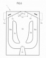
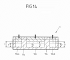
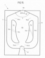
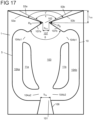
- the shape of the flow chamber 10 of the fluidic component 1 can be changed. How a change in shape can be achieved is explained below using the Figures 4 to 22 described.
- the fluidic component 1 from figure 4 has (in contrast to the fluidic component 1 from Figures 1 to 3 ) no separators and no outlet expansion.
- the outlet channel 107 extends from the inlets 104a1, 104b1 of the bypass channels 104a, 104b to the outlet port 102.
- Sections (parts) of the boundary wall 5, which extend substantially perpendicularly to the plane of oscillation and limit the outlet channel 107, are designed to be movable.
- the movable sections (parts) of the boundary wall 5 are identified by reference numerals 51a, 51b.
- the movable portions (parts) 51a, 51b are each rotatably supported about a rotation axis Ra, Rb extending substantially perpendicular to the plane of oscillation.
- the movable sections (parts) 51a, 51b can be rotated about the axes of rotation Ra, Rb by means of a device (not shown).
- the movable portions (parts) 51a, 51b are rotatable independently of each other, but may be rotated in unison.
- the axes of rotation Ra, Rb are arranged near the entrances 104a1, 104b1 of the bypass channels 104a, 104b.
- the parts 51a, 51b can each have at least one deformable section to allow rotation of the parts 51a, 51b and deformation of the outlet channel 107.
- the parts 51a, 51b can be designed to be elastically and reversibly deformable, at least in sections. So can in Depending on the mass flow (referred to above as internal force) (or the pressure) of the fluid flow entering the fluidic component, the shape of the at least one deformable section and thus the orientation of the parts 51a, 51b change.
- the parts 51a, 51b can act like a flexure joint depending on the mass flow and can perform a rotational movement while stretching or compressing the respective at least one deformable section.
- the cross-sectional area of the outlet opening 102 can increase or decrease, for example, depending on the specific geometric configuration of the parts 51a, 51b and the specific arrangement of the deformable sections within the parts 51a, 51b. With an increasing inlet pressure, the cross-sectional area of the outlet opening can increase. This counteracts the tendency to produce smaller droplets at higher inlet pressures. In this way it can be achieved that by changing the size of the cross-sectional area of the outlet opening, the resulting droplet sizes are hardly dependent on the admission pressure.
- the volume flow at the outlet opening can be kept almost constant despite a change in the admission pressure.
- the oscillation angle and thus largely also the spray angle can be reduced as the inlet pressure increases.
- the movable portions 51a, 51b in the embodiment of FIG figure 4 can rotate through an angle between two maximum deflection positions, one of which is in figure 4 is shown with a solid line and the other with a broken line.
- the maximum deflection positions are in figure 4 shown as an example.
- the movable sections 51a, 51b can steplessly assume any position between the two maximum deflection positions.
- a rotation changes the orientation of the movable sections 51a, 51b to each other and to the rest of the boundary wall 5.
- the angle ⁇ of the outlet channel 107 changes.
- the width b EX of the outlet opening 102 changes deflection position to the other (shown in phantom) maximum deflection position, the movable sections 51a, 51b are rotated such that (increasing the width b EX of the outlet opening 102) the outlet opening 102 shifts downstream. This also changes (increases) the component length I.
- the oscillation angle of the exiting fluid flow and the possible throughflow can be influenced.
- the volume of the outlet channel 107 changes. The angle between the two maximum deflection positions and the location of the The two maximum deflection positions with respect to the longitudinal axis A can be selected depending on the area of application.
- the boundary wall 5 of the flow chamber 10 is formed by the inner surface of a hollow body, with the cavity of the hollow body forming the flow chamber 10 .
- the boundary wall 5 is connected to the outer surface of the hollow body, which determines the outer appearance of the fluidic component.
- the movable portions 51a, 51b of the boundary wall 5 are connected to corresponding portions of the outer surface of the hollow body and rotatable together with them. Accordingly, the external appearance of the fluidic component also changes when the movable sections 51a, 51b rotate.
- the angle ⁇ between the movable sections 51a, 51b of the boundary wall 5 can be changed, for example, by deforming the inner surface of the hollow body in the area of the outlet channel 107.
- the exiting Fluid jet have a strong or sudden change in acceleration or an almost constant time course without sudden changes in acceleration.
- the fluid distribution can be minimally changed within the spray fan within the oscillation angle.
- an edge-accentuated jet is desirable, i.e. an oscillating jet which, on average over time, stays more in the outer than in the inner area of the spray fan.
- the position of the axes of rotation Ra, Rb, the shape of the inner blocks 11, the shape of the separators 105a, 105b (if present), the type of fluid, the inlet pressure and the volume flow can be selected so that the Fluid flow on the average over time as long as possible to the outlet channel 107 (to the sections 51a, 51b of the boundary wall 5, which are aligned perpendicular to the plane of oscillation and are part of the outlet channel 107) applies.
- the angle ⁇ of the outlet extension 108 (if present) can be set smaller than the free oscillation angle of the fluid stream without the outlet extension 108 .
- the embodiment off figure 5 differs from that one figure 4 in particular by the position of the axes of rotation Ra, Rb. Compared to figure 4 is the distance between the rotation axes Ra, Rb to the outlet opening 102 in figure 5 smaller.
- the volume of the outlet channel 107 and the width b EX of the outlet opening 102 change (compared to figure 4 ) less when the movable portions 51a, 51b are rotated through a defined angle.
- the movable sections 51a, 51b can rotate through an angle between two maximum deflection positions, one of which is in figure 5 is shown with a solid line and the other with a broken line.
- the movable sections 51a, 51b can steplessly assume any position between the two maximum deflection positions.
- the movable sections 51a, 51b are rotated in such a way that (with a change (reduction in sections and enlargement in sections) of the width b ⁇ x of the outlet opening 102) shifts the outlet port 102 upstream.
- the angle between the two maximum deflection positions and the location of the two maximum deflection positions with respect to the longitudinal axis A can be selected depending on the area of application.
- the component length I is also changed (shortened) by the rotation of the movable sections 51a, 51b.
- the volume of the outlet channel 107 changes accordingly.
- the rotation of the movable sections 51a, 51b changes the angle ⁇ and also the width b EX of the outlet opening 102.
- the oscillation angle of the exiting fluid flow, the jet impulse and the pressure loss of the component can be changed.
- the jet impulse can be increased (while the internal pressure remains the same) and the cleaning performance can thereby be increased by focusing the jet force.
- the axes of rotation Ra, Rb can be positioned even closer to the outlet opening 102 in order to minimize the coupling between the change in the angle ⁇ and the outlet width b EX or to avoid a change in the outlet width b EX .
- the movable sections 51a, 51b of the boundary wall 5, which delimit the outlet channel 107 perpendicularly to the oscillation plane, are linearly displaced by means of a displacement device (not shown).
- the movable sections 51a, 51b move in the oscillation plane, respectively along an axis lying in the plane defined by the respective movable portion 51a, 51b.
- the displacement device can have a guide device for each movable section 51a, 51b, in which the movable section 51a, 51b is mounted.
- the guiding devices enclose the angle ⁇ (in the plane of oscillation). In addition, this angle between the guide devices can be variable.
- the movable sections 51a, 51b are slidable between two maximum deflections, one of which is shown with a solid line and the other with a dashed line. The maximum deflection positions are in figure 6 shown as an example.
- the spray behavior such as the oscillation angle
- the spray angle ⁇ By shifting the movable sections 51a, 51b, the spray behavior, such as the oscillation angle, of the fluid flow can be changed. On the one hand, this changes the spray angle ⁇ . If the width b EX of the outlet opening 102 is increased, the oscillation angle is also increased and the spray pulse (with the flow rate remaining the same) is reduced. This is advantageous, for example, for cleaning or wetting (sensitive) surfaces.
- the nozzle size can be changed by changing the width b EX of the outlet opening 102, ie the flow can be regulated with a constant inlet pressure of the fluid.
- a screen-like device can be provided in the area of the outlet opening 102, which extends essentially perpendicularly to the longitudinal axis A and by means of which the cross-sectional area of the outlet opening can be changed without influencing the angle ⁇ .
- the movable sections 51a, 51b can be displaced in the plane of oscillation transversely to the longitudinal axis A in order to change the cross-sectional area of the outlet opening without changing the angle ⁇ .
- the embodiment off figure 7 differs from that one figure 6 particularly in the direction along which the movable portions 51a, 51b are slidable.
- the movable sections 51a, 51b are displaceable along the longitudinal axis A of the fluidic component. With such a shift, the outlet width b ⁇ x and the angle ⁇ remain unchanged. Only the volume of the outlet channel 107 and the component length I of the fluidic component 1 change through the in figure 7 shift shown. It can thus be achieved that the oscillation angle changes only slightly, while the oscillation frequency and the time profile of the emerging fluid flow change significantly.
- one of the maximum deflection positions is shown with a solid line, the other with a dashed line.
- the positions are only examples.
- the two movable sections 51a, 51b can be moved independently of one another. As a result, the oscillation angle and the direction of the exiting fluid flow can be changed. For example, when the movable portion 51a is moved downstream and the movable portion 51b is moved upstream, the direction of the exiting fluid flow changes toward the movable portion 51b moved upstream.
- the two movable sections 51a, 51b can also be moved simultaneously in the same way (direction, speed). This can be achieved, for example, by a telescoping structure of the fluidic component 1 .
- the movable sections 51a, 51b are displaced along the longitudinal axis A with respect to the remaining fluidic component 1 by means of rails.
- the material of the movable sections 51a, 51b (or the other movable elements) can comprise a harder or more wear-resistant material than the rest of the boundary wall 5.
- the fluidic component could 1 can be made of a stainless steel and the movable sections 51a, 51b (or the other movable elements) can be made of a ceramic material.
- the shape of the flow chamber 10 is not achieved by changing the boundary wall 5, but by changing the inner blocks 11a, 11b.
- the two inner blocks 11a, 11b can be changed jointly or independently of one another.
- the two inner blocks can be modified in the same way or differently.
- the change in the inner blocks 11a, 11b consists in a change in the position of the inner blocks 11a, 11b by movement, in particular rotation, of the inner blocks 11a, 11b.
- the rotation can be performed by an unillustrated device. The rotation takes place around the axes of rotation Ra, Rb, extending substantially perpendicular to the plane of oscillation, between two maximum deflection positions. A maximum deflection position is shown as an example with a dashed line, while the other maximum deflection position is shown as an example with a solid line.
- the axes of rotation Ra, Rb are each located in an area of the inner blocks 11a, 11b facing the inlet opening 101 and the main flow channel 103.
- the axes of rotation Ra, Rb are arranged symmetrically with respect to the longitudinal axis A.
- the embodiment off figure 9 differs from that one figure 8 with regard to the position of the axes of rotation Ra, Rb. So the axes of rotation are in figure 9 located further upstream. This changes in the embodiment figure 9 the volume of the main flow channel 103 less than in figure 8 , when the inner blocks 11a, 11b rotate through the same angle.
- the inner blocks 11a, 11b may not be rotated about an axis of rotation, but may be displaced in the plane of oscillation to change the shape of the flow chamber 10.
- the cross-sectional areas of the inlets 104a1, 104b1 and outlets 104a2, 104b2 of the bypass channels can be changed.
- the width of the main flow channel 103 and the secondary flow channels 104a, 104b (in the second section) can be changed.
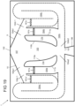
- FIG 10 two different embodiments for changing the inner blocks 11a, 11b are shown.
- the inner block 11a shown on the left is changed by deformation, in particular by deformation of the inwardly pointing surface 110a of the inner block 11a.
- the inner surface 110a faces the main flow channel 103 and extends substantially perpendicular to the plane of oscillation.
- the surface 110a to be deformed can include, for example, a spring material that can assume two stable or metastable states and can be moved back and forth between these two states by the action of an external force (by a device) or by a so-called internal force.
- the so-called internal force can result from the pressure of the fluid stream flowing in the fluidic component.
- the material of the surface 110a to be deformed in terms of material thickness and elasticity
- the material of the surface 110a to be deformed (in terms of material thickness and elasticity) can be selected such that it deforms when there is a pressure change at the inlet opening, at which the flow property in the flow chamber 10 should change , (for low-pressure cleaning) of 5 bar or (for high-pressure cleaning) of 10 bar occurs.
- This pressure data can also be used to select a suitable material for the deformable sections of the parts 51a, 51b mentioned above.
- a so-called intelligent material such as a shape memory alloy can also be used.
- the deformation of the inwardly facing surface 110a of the inner block 11a can be predetermined by additional pivots 110a1 and fixed points 110a2.
- the wall thickness of the inwardly pointing surface 110a of the inner block 11a can be designed with different thicknesses in sections, so that the deformability (resilience) of the material is selectively changed in sections and the surface 110a can then be correspondingly deformed when external forces are applied.
- the inwardly pointing surface 110a of the inner block 11a is preferably shaped in such a way that the main flow channel 103 widens or diverges continuously downstream.
- the inward-facing surface 110a of the inner block 11a is preferably shaped such that the main flow channel 103 first diverges (widens) downstream and converges along the longitudinal axis A at the level of the last third of the inner block 11a (diverges). tapered). (Basically, other shapes can also be assumed in the stable or metastable states.)
- the change in the shape of the main flow channel 103 brought about in this way reduces the change in acceleration of the fluid flow over time, or the change in acceleration assumes an approximately sinusoidal curve.
- the surface 110a pointing inwards is formed by a flat surface or a curved surface with a large radius of curvature.
- the inwardly facing surface 110a can also comprise polygons or splines, in order thus for the most part to form an almost constant angle ⁇ between the inner blocks 11a, 11b. This allows wedges are formed on the inwardly facing surface 110a which protrude into the main flow channel 103.
- the inner block 11a, 11b is constructed in such a way that the fin ray effect or the so-called fin ray effect can be utilized.
- a defined curvature of the inner delimiting wall 110a, 110b of the main flow channel 103 can be achieved with the aid of a displacement or a force effect at one point.
- This fin jet effect can also be used to specifically change the size of the cross-sectional area of the outlet opening, for example by changing the shape of sections 51a, 51b.
- the inner block 11b shown on the right is made up of two parts 11b1, 11b2.
- the dividing line between the two parts 11b1, 11b2 extends essentially from the inlet 104b1 to the outlet 104b2 of the bypass channel 104b.
- the two parts 11b1, 11b2 can be moved (slidably or rotatably) independently of one another in the plane of oscillation. In figure 10 the two parts 11b1, 11b2 are, for example, displaceable.
- the part 11b1 (11b2) facing the main flow channel 103 (side flow channel 104b) By shifting the part 11b1 (11b2) facing the main flow channel 103 (side flow channel 104b), the volume and shape of the main flow channel 103 (side flow channel 104b) can be changed, while the geometry of the side flow channel 104b (main flow channel 103) remains essentially unchanged.
- a channel 112b can arise, which essentially extends from the inlet 104b1 to the outlet 104b2 of the bypass channel 104b.
- a leakage flow between the main flow channel 103 and the secondary flow channel 104b can be avoided by the alignment of this channel 112b.
- the oscillation angle and/or the course over time of the moving fluid jet can be adjusted.
- the deformation of the inner block was described only in relation to the left inner block and the two-part design of the inner block only in relation to the right inner block, both embodiments can be applied to both inner blocks, respectively.
- the shape of the flow chamber 10 is changed by changing the cross-sectional area of the bypass channels 104a, 104b.
- the boundary wall 5 of the flow chamber 10 has a deformable section 52a, 52b downstream of each inlet 104a1, 104a2 of the bypass channels 104a, 104b.
- the deformable sections 52a, 52b are formed symmetrically with respect to the longitudinal axis A. However, only one such deformable section or two deformable sections that are not symmetrical with respect to the longitudinal axis A can also be provided.
- the local deformability of the material of the boundary wall 5 in the sections 52a, 52b can be achieved, for example, by a lower material thickness (compared to the rest of the boundary wall 5) or by a different composition of the material.
- the user can deform the deformable sections 52a, 52b in a targeted manner by means of a device that is not shown.
- the deformed sections 52a, 52b protrude into the bypass channels 104a, 404b transversely to the flow direction of the fluid flow in the bypass channels 104a, 104b.
- a deformed state of the deformable sections 52a, 52b is shown by way of example, not the non-deformed state of the deformable sections 52a, 52b.
- the deformable sections 52a, 52b can also be provided at a different position, for example closer to the outlets 104a2, 104b2 of the bypass channels 104a, 104b.
- the cross-sectional area of the bypass channels 104a, 104b can also be changed by means of a slide that can be moved into the bypass channels 104a, 104b transversely to the direction of flow in the bypass channels 104a, 104b.
- the oscillation frequency can essentially be changed in the case of compressible fluids. (However, if the cross-sectional area of the bypass channels 104a, 104b is reduced too much, the oscillation can come to a standstill.) A fan beam can thereby be generated which extends orthogonally to the original plane of oscillation.
- a fluidic component 1 in which the width b IN of the inlet opening 101 can be changed.
- the wall forming the funnel-shaped projection 106 is designed in several parts.
- the funnel-shaped extension is arranged upstream of the inlet opening 101 .
- the wall of the funnel-shaped extension 106 accordingly has two sections 1061a, 1061b which extend essentially transversely to the plane of oscillation.
- the position of the two sections 1061a, 1061b is in the Oscillation level and transverse to the longitudinal axis A displaceable.
- the width of the funnel-shaped extension 106 and thus of the inlet opening 101 can be changed.
- changing the width b IN of the inlet opening 101 can change the spray characteristics of the exiting fluid flow between a almost punctiform beam and an oscillating fan beam. In this way, for example, the area performance of the fluidic component can be adjusted depending on the task.
- the component length I of the fluidic component 1 is designed to be variable.
- the boundary wall 5 is designed telescopically or like a bellows. This requires the boundary wall 5 to be constructed in at least two parts, one of the two parts being able to be pushed along the longitudinal axis A into the other of the two parts or pulled out of the latter.
- the fluidic component 1 is shown by way of example in two different states, each of which has different component lengths I, I'.
- the part of the boundary wall 5 that can be displaced relative to the other part is shown in dashed lines and in solid lines.
- the inner blocks 11a, 11b are also designed telescopically or bellows-like in order to adapt the length I 11 , I 11 ′ of the inner blocks 11a, 11b according to the component length I, I′ of the fluidic component 1 .
- the length I of the fluidic component 1 and the length I 11 of the inner blocks 11a, 11b can be changed independently of one another or in a coupled manner. According to a further embodiment, either only the length I 11 , I 11 ′ of the inner blocks 11a, 11b or the component length I, I′ of the fluidic component 1 can be changed.
- the temporal jet course of the exiting fluid jet and the oscillation angle can be changed.
- the temporal beam curve approaches a square-wave function. If the component length is further increased when the rectangular function is reached, the oscillation angle decreases until finally a quasi-static hole jet is created.
- the orientation of the inwardly facing surfaces 110a, 110b of the inner blocks 11a, 11b can also change, so that the angle ⁇ changes at the same time. Therewith the change in the oscillation angle can be amplified. This is the case, for example, when the length I 11 of the inner blocks 11a, 11b is changed, the distance between the inner blocks 11a, 11b (in the plane of oscillation and transverse to the longitudinal axis A) remains unchanged.
- figure 14 shows one of the principle of figure 13 similar embodiment.
- the component depth t is variable.
- the cross-sectional area (transverse to the longitudinal axis A) of the main flow channel 103 and the secondary flow channels 104a, 104b can be changed.
- the boundary wall 5 and the inner blocks 11a, 11b are designed in the manner of a telescope or stamp and can be adjusted by means of a device (not shown).
- the oscillation angle can be changed. The oscillation angle is reduced when the component depth t is reduced.
- figure 15 12 shows a fluidic component 1 with two inner blocks 11a, 11b, each of which has a channel 113a, 113b which extends through the inner blocks 11a, 11b.
- Each channel 113a, 113b is aligned in such a way that it fluidly connects the main flow channel 103 to the secondary flow channel 104a, 104b, which is separated from the main flow channel 103 by the respective inner block 11a, 11b.
- the orientation of the channels 113a, 113b is in figure 15 as an example and shown differently for the two inner blocks 11a, 11b.
- the two channels 113a, 113b can be aligned symmetrically (with respect to the longitudinal axis A).
- the channels 113a, 113b can also occupy other positions within the inner blocks 11a, 11b than in FIG figure 15 shown. Also, multiple channels can be formed within an inner block.
- the channels 113a, 113b are designed to be closable, so that a fluid connection between the main flow channel 103 and the secondary flow channels 104a, 104b can be established by means of the channels 113a, 113b.
- the bypass channels 104a, 104b can be designed to be closable.
- the main flow channel 103 can be fluidically connected to the corresponding side flow channel 104a, 104b either via the channel 113a, 113b or via the input 104a1, 104b1 and the output 104a2, 104b2 of the side flow channels 104a, 104b.
- the oscillation frequency of the fluid flow and the temporal course of the emerging fluid jet can be changed.
- the embodiment off figure 16 provides for changing the shape of the flow chamber 10 by deforming the inner blocks 11a, 11b.
- the inner blocks 11a, 11b each have two deformable areas 152a, 153a, 152b, 153b. These are respectively facing the main flow passage 103 and formed in the inward facing surfaces 110a, 110b of the inner blocks 11a, 11b.
- Each of the deformable areas can take two forms. Each shape can correspond to a (meta)stable state of the material, so that when the shape changes, the material switches back and forth between the (meta)stable states.
- the two deformable zones of an inner block are arranged downstream one behind the other.
- the two deformable areas 152a, 153a of one inner block 11a are identical (in terms of shape, deformation and position) to the deformable areas 152b, 153b of the other inner block 11b.
- the two forms that these can assume are shown.
- one of the two shapes is shown with a broken line and the other of the two shapes with a solid line.
- the deformable areas 152a, 152b, 153a, 153b can be deformed individually, with a deformable area of one inner block and the corresponding deformable area of the other inner block preferably being shaped in the same way, so that a total of four combinations are possible.
- Regions 152a, 152b, 153a, 153b are deformable by means of a device operable by the user. The deformation changes the shape of the main flow channel 103, which leads to a change in the oscillation angle of the emerging fluid flow.
- the areas 152a, 153a, 152b, 153b can be moved into or out of the main flow channel 103 in the plane of oscillation by a ram-like movement of a device (not shown).
- An outlet enlargement 108 can additionally be provided downstream of the outlet opening 102 . This is for example in the embodiments from the figures 1 and 17 shown.
- the outlet enlargement 108 preferably has a length l 108 (extension along the longitudinal axis A) which is at least 25% of the outlet width b EX .
- the spray jet is thus guided within the oscillation level and thus leads to an increase in the spray impulse.
- the additional outlet extension 108 is particularly advantageous for cleaning applications.
- the outlet extension comprises two sections 53a, 53b of the boundary wall, which extend substantially perpendicularly to the plane of oscillation. These two sections 53a, 53b can be movable, in particular rotatable about an axis which extends substantially perpendicular to the plane of oscillation.
- the two sections 53a, 53b are rotatable about the axes of rotation Ra, Rb.
- the axes of rotation Ra, Rb are arranged at the transition between the outlet channel 107 and the outlet enlargement 108, that is to say (viewed along the longitudinal axis A) at the level of the outlet opening 102.
- These can also be arranged differently, similar to what is shown in figure 4 or figure 5 is shown as an example.
- the axes of rotation Ra, Rb are located slightly outside of the outlet port 102.
- the axes of rotation Ra, Rb can be located precisely at the upstream end of the two sections 53a, 53b.
- the angle ⁇ between the two sections 53a, 53b of the outlet enlargement can be changed by rotating the two sections 53a, 53b about the axes of rotation Ra, Rb.
- the rotation can be driven by a device not shown.
- Another variant for setting the angle ⁇ is when the axes of rotation Ra, Rb are located in the vicinity of the outlet opening 102, i.e. are displaced along the longitudinal axis A upstream or downstream with respect to the outlet opening 102.
- the shape of the outlet opening 102 is variable.
- the outlet opening 102 has a radius 109, 109′, 109′′, the size of which can be changed. If the radius 109, 109′, 109′′ is changed, the shape of the adjoining sections of the boundary walls of the outlet channel 107 and the Outlet extension 108 and, where appropriate, the angle ⁇ come.
- the outlet opening 102 is shown with a sharp edge as a solid line. Here the radius 109 is equal to zero.
- Alternative shapes of the outlet opening 102 are shown as dashed lines.
- the outlet opening (viewed in the oscillation plane) has a radius of 109 ⁇ on the left and a radius of 109" on the right, which are different in size and each greater than zero degrees.
- a body 190 that can be displaced in the oscillation plane which, by displacement, exerts a force on the material that delimits the outlet opening 102 and the adjacent areas of the outlet channel 107 and the outlet enlargement 108 and is elastically deformable is, can exert and thus bring about a deformation of the elastic material.
- the displacement of the body 190 is in figure 18 indicated by a double arrow.
- FIG 19 shows a further embodiment in which four bypass channels 104a, 104a', 104b, 104b' are formed.
- two side-flow ducts 104a, 104a' or 104b, 104b' form a unit in which the two side-flow ducts are connected in parallel.
- the other bypass channel of the unit is closed at this point in time by means of a partition 181a, 181a', 181b, 181b'.
- the partition walls 181a, 181a', 181b, 181b' can be moved into and out of the bypass channels by means of a device that is not shown.
- the partition walls of a unit can be coupled in this way be that a movement of a dividing wall 181a, 181b into the corresponding bypass duct 104a, 104b is linked to a movement of the other dividing wall 181a', 181b' out of the corresponding other bypass duct 104a', 104b'.
- the fluid only flows through the bypass channel, which is not closed by a partition.
- the two bypass channels 104a, 104a' and 104b, 104b' of a unit have a different shape. By actuating the device, the bypass channel can thus be released and flowed through, which has the shape required to generate the desired jet profile of the fluid flow at the outlet opening.
- each unit is identical and are each aligned mirror-symmetrically with respect to the main flow channel 103 .
- Each unit has a shorter 104a, 104b and a longer 104a', 104b' bypass duct. While the shorter side-flow channel 104a, 104b runs predominantly in a straight line, the longer side-flow channel 104a', 104b' strings together three predominantly straight, parallel sections in a meandering manner. The number of sections can also differ from three.
- Flowable elements 200, 200 ⁇ , 200" are provided, which protrude into the flow chamber 10 transversely to the oscillation plane in the area of the inlet 104a1, 104b1 and the outlet 104b2 of the bypass channels 104a, 104b.
- the arrangement in the area of the inlets 104a1, 104b1 and the outlet 104b2 is only an example insofar as any combination of the inputs 104a1, 104b1 and the outputs 104a2, 104b2 is conceivable.
- FIG 20 different configurations (shape, relative arrangement) of the flow-around elements 200, 200', 200" are shown, whereby these configurations are also only to be understood as examples.
- a flow-around element 200 is shown, which is shown in Oscillation plane has an elliptical cross-section and which is rotatable about an axis which extends substantially perpendicularly to the oscillation plane.
- the rotatability is indicated by the curved double arrow.
- the axis of rotation is here in the center of the element 200, but can also be eccentric.
- other shapes can also be used, preferably those (elongated) shapes which, when rotated, result in a significant change in the shape of the inlet 104a1 of the bypass channel 104a.
- a plurality of elements 200' (here three by way of example) around which a flow can flow are shown, which have a round cross-section (here by way of example) in the oscillation plane and in the oscillation plane are movable.
- a device provided for displacing the elements 200' is in figure 20 not shown. The displaceability is indicated by double arrows.
- a translationally adjustable element 200" is shown, which is sickle-shaped in the oscillation plane (here by way of example).
- the element 200" is attached to a device 201, which is used to change the position and/or the orientation of the Element 200 "is used.
- the position of the adjustable element 200 " can additionally influence the flow in the main flow channel, and thus the spray characteristics of the exiting fluid flow can be adjusted in a targeted manner.
- the elements 200, 200', 200" shown can be moved between two positions or several positions (e.g. intermediate positions between the two positions) or can be moved continuously. The extent of the movement is limited to the elements 200, 200', 200" in remain in the respective inlet or outlet region 104a1, 104b1, 104a2, 104b2 and in particular do not reach the outlet channel 107 or main flow channel 103.
- FIG. 21 and 22 another embodiment is shown.
- figure 22 a sectional view through the fluidic component figure 21 transverse to the plane of oscillation along the line A'-A".
- the fluidic component has two bypass channels 104a, 104b, each of which has an opening 170a, 170b.
- the openings 170a, 170b are here, for example, approximately in the middle between the inlet 104a1, 104b1 and the exit 104a2, 104b2 of each bypass passage 104a, 104b
- the openings 170a, 170b may also be arranged at other positions between the entrance 104a1, 104b1 and the exit 104a2, 104b2 of the bypass passages 104a, 104b
- the two openings 170a, 170b are essentially at the same height in the fluid flow direction (or along the line A ⁇ -A") considered.
- the openings 170a, 170b are each formed in the front wall 12 of the fluidic component.
- a closable connecting channel 170 opens out into the two openings 170a, 170b
- the openings 170a, 170b and the connecting channel 170 have in the embodiment of FIG figures 21 and 22 a rectangular cross section. However, other cross-sectional shapes are also possible.
- the connecting channel 170 can be closed by means of a partition wall 171 which can be moved (transversely to the fluid flow direction) into and out of the connecting channel 170 (by means of rotation or translation).
- the partition wall 171 can be located at any point between the openings 170a, 170b.
- a partition wall 171 can be provided in each case, which already separates the secondary flow channels 104a, 104b from the connecting channel 170 in the region of the openings 170a, 170b.
- the position of the partition wall 170 can be changed by means of a mechanism that is not shown.
- the component depth t of the fluidic component is shown as constant as an example. Alternatively, the component depth t cannot be constant.
- an eccentric can be used instead of the axis of rotation. This makes it possible to reduce the connection between an angle change (e.g. the angle ⁇ or the angle ⁇ ) and a change in distance (e.g. the outlet width b EX or between the ends of the inner blocks 11a, 11b facing the inlet opening) or to change the angle, without changing the distance at the same time.
- an angle change e.g. the angle ⁇ or the angle ⁇
- a change in distance e.g. the outlet width b EX or between the ends of the inner blocks 11a, 11b facing the inlet opening
- the movement of these parts can be coupled or independent of one another and can be simultaneous or staggered in time.
- the speed at which the movement takes place can also be the same or different for the several parts.
Landscapes
- Nozzles (AREA)
- Reciprocating Pumps (AREA)
Claims (14)
- Composant fluidique (1) comportant une chambre d'écoulement (10) qui peut être traversée par un courant de fluide qui entre dans la chambre d'écoulement (10) par une ouverture d'entrée (101) de la chambre d'écoulement (10) et qui sort de la chambre d'écoulement (10) par une ouverture de sortie (102) de la chambre d'écoulement (10), dans lequel au moins un moyen (104a, 104b) pour former une oscillation du courant de fluide à l'ouverture de sortie (102) est prévu dans la chambre d'écoulement (10), dans lequel la chambre d'écoulement (10) comprend un canal d'écoulement principal (103) qui relie l'ouverture d'entrée (101) et l'ouverture de sortie (102), et au moins un canal d'écoulement secondaire (104a, 104b) en tant que moyen pour former une oscillation du courant de fluide à l'ouverture de sortie (102), dans lequel le canal d'écoulement principal (103) et l'au moins un canal d'écoulement secondaire (104a, 104b) sont séparés l'un de l'autre par au moins un bloc intérieur (11a, 11b),
caractérisé en ce que
la chambre d'écoulement (10) présente une forme modifiable et est délimitée par une paroi de délimitation (5),- dans lequel un élargissement de sortie (108) se raccorde en aval de l'ouverture de sortie (102), qui s'élargit vers l'aval à partir de l'ouverture de sortie (102), dans lequel l'élargissement de sortie (108) comprend deux parties (53a, 53b) de la paroi de délimitation, qui s'étendent sensiblement perpendiculairement à un plan d'oscillation et qui sont réalisées de manière mobile par rapport au reste de la paroi de délimitation et/ou- dans lequel, afin de modifier la forme de la chambre d'écoulement (10), l'au moins un bloc intérieur (11a, 11b) est déformable et/ou mobile par rapport à la paroi de délimitation (5). - Composant fluidique (1) selon la revendication 1, caractérisé en ce que la paroi de délimitation (5) comprend au moins une partie (52a, 52b, 53a, 53b) qui est déformable.
- Composant fluidique (1) selon la revendication 2, caractérisé en ce que ladite au moins une partie (52a, 52b) de la paroi de délimitation (5), qui est déformable, forme par sections l'au moins un canal d'écoulement secondaire (104a, 104b).
- Composant fluidique (1) selon la revendication 2 ou 3, caractérisé en ce que ladite au moins une partie de la paroi de délimitation (5), qui est déformable, délimite l'ouverture de sortie (102).
- Composant fluidique (1) selon l'une quelconque des revendications précédentes, caractérisé en ce que la paroi de délimitation (5) comporte au moins deux parties (51a, 51b, 53a, 53b), l'une des deux parties étant mobile, en particulier déplaçable ou rotative, par rapport à l'autre des deux parties.
- Composant fluidique (1) selon la revendication 5, caractérisé en ce que la chambre d'écoulement (10) comprend, en amont de l'ouverture de sortie (102), un canal de sortie (107) qui débouche dans l'ouverture de sortie (102) à son extrémité aval, le canal de sortie (107) étant formé par sections par deux parties (51a, 51b) de la paroi de délimitation (5) qui sont mobiles, en particulier déplaçables ou rotatives, par rapport à une troisième partie de la paroi de délimitation.
- Composant fluidique (1) selon la revendication 6, caractérisé en ce que l'oscillation du courant de fluide est formée dans un plan d'oscillation, les deux parties (51a, 51b) de la paroi de délimitation (5), qui forment par sections le canal de sortie (107), s'étendant sensiblement perpendiculairement au plan d'oscillation et formant un angle (δ) dans le plan d'oscillation, les deux parties (51a, 51b) de la paroi de délimitation (5), qui forment par sections le canal de sortie (107), en particulier pouvant être tournées par rapport à la troisième partie de la paroi de délimitation (5) en modifiant l'angle (δ).
- Composant fluidique (1) selon la revendication 7, caractérisé en ce que les deux parties (51a, 51b) de la paroi de délimitation (5), qui forment par sections le canal de sortie (107), sont déplaçables par rapport à la troisième partie de la paroi de délimitation (5) en modifiant la largeur (bEX) de l'ouverture de sortie (102).
- Composant fluidique (1) selon l'une quelconque des revendications 5 à 8, caractérisé en ce qu'au moins l'une des deux parties (51a, 51b) de la paroi de délimitation (5), qui forment par sections le canal de sortie (107), comprend au moins une partie déformable.
- Composant fluidique (1) selon l'une quelconque des revendications précédentes, caractérisé en ce que ledit au moins un bloc intérieur (11b) est réalisé en deux parties et en ce que l'une partie (11b1) du bloc intérieur (11b) est mobile par rapport à l'autre partie (11b2) du bloc intérieur (11b) ou en ce que les deux parties (11b1, 11b2) du bloc intérieur (11b) sont mobiles indépendamment l'une de l'autre par rapport à la paroi de délimitation (5).
- Composant fluidique (1) selon l'une quelconque des revendications précédentes, caractérisé en ce que ledit au moins un bloc intérieur (11a, 11b) comprend un canal (113a, 113b) qui s'étend à travers ledit au moins un bloc intérieur (11a, 11b) de telle sorte que ledit canal (113a, 113b) relie de manière fluidique ledit canal d'écoulement principal (103) et ledit au moins un canal d'écoulement secondaire (104a, 104b), dans lequel en particulier ledit canal (113a, 113b) et/ou ledit au moins un canal d'écoulement secondaire (104a, 104b) peut/peuvent être fermé(s).
- Composant fluidique (1) selon l'une quelconque des revendications précédentes, caractérisé en ce que le composant fluidique (1) présente une longueur de composant (I), une largeur de composant (b) et une profondeur de composant (t), la longueur de composant (l) étant définie le long d'une direction qui s'étend sensiblement de l'ouverture d'entrée (101) à l'ouverture de sortie (102), et la largeur de composant (b) et la profondeur de composant (t) étant définies respectivement perpendiculairement l'une à l'autre et à la longueur de composant (I), l'expansion de la chambre d'écoulement (10) étant variable le long de la longueur de composant (I), de la profondeur de composant (t) ou de la largeur de composant (b), la paroi de délimitation (5) en particulier étant réalisée de manière télescopique le long de la longueur de composant (I), de la profondeur de composant (t) ou de la largeur de composant (b).
- Composant fluidique (1) selon l'une quelconque des revendications précédentes, caractérisé en ce que l'élargissement de la sortie (108) forme un angle (ε) dans le plan d'oscillation et l'angle (ε) de l'élargissement de la sortie (108) étant variable, il étant prévu en particulier que les deux parties (53a, 53b) de la paroi de délimitation peuvent tourner respectivement autour d'un axe de rotation (Ra, Rb) qui s'étend respectivement perpendiculairement au plan d'oscillation, l'angle (ε) de l'élargissement de la sortie (108) étant modifié par une rotation des parties (53a, 53b) autour les axes de rotation (Ra, Rb).
- Composant fluidique (1) selon l'une quelconque des revendications précédentes, caractérisé en ce que le composant fluidique (1) comporte un dispositif pour modifier de manière ciblée la forme de la chambre d'écoulement (10).
Applications Claiming Priority (2)
| Application Number | Priority Date | Filing Date | Title |
|---|---|---|---|
| DE102017212747.3A DE102017212747B3 (de) | 2017-07-25 | 2017-07-25 | Fluidisches Bauteil, fluidische Baugruppe und Fluidverteilungsgerät |
| PCT/EP2018/069785 WO2019020516A1 (fr) | 2017-07-25 | 2018-07-20 | Élément fluidique |
Publications (3)
| Publication Number | Publication Date |
|---|---|
| EP3658290A1 EP3658290A1 (fr) | 2020-06-03 |
| EP3658290C0 EP3658290C0 (fr) | 2023-06-07 |
| EP3658290B1 true EP3658290B1 (fr) | 2023-06-07 |
Family
ID=63108519
Family Applications (1)
| Application Number | Title | Priority Date | Filing Date |
|---|---|---|---|
| EP18750113.5A Active EP3658290B1 (fr) | 2017-07-25 | 2018-07-20 | Élément fluidique |
Country Status (7)
| Country | Link |
|---|---|
| US (1) | US20210138487A1 (fr) |
| EP (1) | EP3658290B1 (fr) |
| CN (1) | CN110997154A (fr) |
| AU (1) | AU2018305878A1 (fr) |
| CA (1) | CA3070911A1 (fr) |
| DE (1) | DE102017212747B3 (fr) |
| WO (1) | WO2019020516A1 (fr) |
Families Citing this family (21)
| Publication number | Priority date | Publication date | Assignee | Title |
|---|---|---|---|---|
| US10144394B1 (en) * | 2017-11-08 | 2018-12-04 | Uber Technologies, Inc. | Nozzles and systems for cleaning vehicle sensors |
| CN109604078B (zh) * | 2019-01-02 | 2023-08-29 | 北京科技大学 | 一种双腔室水射流自振喷嘴装置 |
| US11739517B2 (en) | 2019-05-17 | 2023-08-29 | Kohler Co. | Fluidics devices for plumbing fixtures |
| US12595649B2 (en) | 2019-05-17 | 2026-04-07 | Kohler Co. | Fluidics devices for plumbing fixtures |
| US10753154B1 (en) | 2019-10-17 | 2020-08-25 | Tempress Technologies, Inc. | Extended reach fluidic oscillator |
| US11751365B2 (en) * | 2019-10-29 | 2023-09-05 | Alliance For Sustainable Energy, Llc | Jet impingement manifolds for cooling power electronics modules |
| JP7541879B2 (ja) * | 2020-09-08 | 2024-08-29 | 株式会社Lixil | 吐出装置 |
| CN112722248A (zh) * | 2021-02-22 | 2021-04-30 | 上海交通大学 | 一种机翼无气源振荡射流流动控制装置 |
| CN114370650B (zh) * | 2022-01-14 | 2023-05-23 | 中国航空发动机研究院 | 一种亚毫米自激扫掠喷射振荡器 |
| CN114353306A (zh) * | 2022-01-20 | 2022-04-15 | 上海理工大学 | 流体振荡器动态送风装置 |
| CN114459118B (zh) * | 2022-02-28 | 2022-09-02 | 海信空调有限公司 | 空调的控制方法、装置、空调及存储介质 |
| CN114623494B (zh) * | 2022-02-28 | 2022-11-25 | 海信空调有限公司 | 空调器 |
| CN114440311A (zh) * | 2022-02-28 | 2022-05-06 | 海信(山东)空调有限公司 | 空调器的振荡器以及空调器 |
| WO2023159944A1 (fr) * | 2022-02-28 | 2023-08-31 | 海信空调有限公司 | Climatiseur |
| WO2023159943A1 (fr) * | 2022-02-28 | 2023-08-31 | 海信空调有限公司 | Climatiseur |
| CN114459072A (zh) * | 2022-02-28 | 2022-05-10 | 海信(山东)空调有限公司 | 空调器 |
| CN115751456A (zh) * | 2022-10-25 | 2023-03-07 | 厦门呼博仕智能健康科技股份有限公司 | 一种基于流体振荡器的空气调节器及其使用方法 |
| CN115540324A (zh) * | 2022-11-02 | 2022-12-30 | 海信空调有限公司 | 空调器 |
| CN115899812A (zh) * | 2022-11-15 | 2023-04-04 | 海信空调有限公司 | 空调器 |
| CN115751448A (zh) * | 2022-11-15 | 2023-03-07 | 海信空调有限公司 | 空调器 |
| EP4716377A1 (fr) * | 2024-09-20 | 2026-03-25 | Siemens Healthineers AG | Chemise de refroidissement pour refroidir un composant à refroidir d'un dispositif de génération de rayonnement et dispositif de génération de rayonnement |
Citations (2)
| Publication number | Priority date | Publication date | Assignee | Title |
|---|---|---|---|---|
| US4508267A (en) * | 1980-01-14 | 1985-04-02 | Bowles Fluidics Corporation | Liquid oscillator device |
| US6497375B1 (en) * | 2000-02-22 | 2002-12-24 | Bowles Fluidics Corporation | Fluidic nozzle with multiple operating modes |
Family Cites Families (13)
| Publication number | Priority date | Publication date | Assignee | Title |
|---|---|---|---|---|
| US4151955A (en) * | 1977-10-25 | 1979-05-01 | Bowles Fluidics Corporation | Oscillating spray device |
| US4231519A (en) * | 1979-03-09 | 1980-11-04 | Peter Bauer | Fluidic oscillator with resonant inertance and dynamic compliance circuit |
| AU544839B2 (en) * | 1980-01-14 | 1985-06-13 | Bowles Fluidics Corporation | Liquid oscillator device |
| US4930357A (en) * | 1986-11-21 | 1990-06-05 | Allied-Signal Inc. | Fluidic volumetric fluid flow meter |
| US6729564B2 (en) | 2000-07-21 | 2004-05-04 | Bowles Fluidics Corporation | Fluidic SPA Nozzles with dual operating modes and methods |
| JP2005059651A (ja) * | 2003-08-08 | 2005-03-10 | Asmo Co Ltd | 車両用ウォッシャノズル及び車両用ウォッシャ装置 |
| US7354008B2 (en) * | 2004-09-24 | 2008-04-08 | Bowles Fluidics Corporation | Fluidic nozzle for trigger spray applications |
| US7128082B1 (en) * | 2005-08-10 | 2006-10-31 | General Electric Company | Method and system for flow control with fluidic oscillators |
| US8985483B2 (en) * | 2012-01-24 | 2015-03-24 | John E. Petrovic | Adjustable trajectory spray nozzles |
| CN105121025B (zh) * | 2012-12-12 | 2018-09-11 | 鲍尔斯应用流体力学公司 | 射流喷嘴和振荡器回路 |
| EP3122466A4 (fr) * | 2014-03-27 | 2017-11-15 | dlhBowles Inc. | Ensemble buse modulaire et appareil de plaque fluidique et procédé pour créer sélectivement des motifs de pulvérisation 2-d ou 3-d |
| DE102015222771B3 (de) * | 2015-11-18 | 2017-05-18 | Technische Universität Berlin | Fluidisches Bauteil |
| JP6656581B2 (ja) * | 2015-12-15 | 2020-03-04 | Toto株式会社 | 吐水装置 |
-
2017
- 2017-07-25 DE DE102017212747.3A patent/DE102017212747B3/de not_active Expired - Fee Related
-
2018
- 2018-07-20 AU AU2018305878A patent/AU2018305878A1/en not_active Abandoned
- 2018-07-20 WO PCT/EP2018/069785 patent/WO2019020516A1/fr not_active Ceased
- 2018-07-20 EP EP18750113.5A patent/EP3658290B1/fr active Active
- 2018-07-20 CA CA3070911A patent/CA3070911A1/fr active Pending
- 2018-07-20 US US16/634,549 patent/US20210138487A1/en not_active Abandoned
- 2018-07-20 CN CN201880050429.8A patent/CN110997154A/zh active Pending
Patent Citations (2)
| Publication number | Priority date | Publication date | Assignee | Title |
|---|---|---|---|---|
| US4508267A (en) * | 1980-01-14 | 1985-04-02 | Bowles Fluidics Corporation | Liquid oscillator device |
| US6497375B1 (en) * | 2000-02-22 | 2002-12-24 | Bowles Fluidics Corporation | Fluidic nozzle with multiple operating modes |
Also Published As
| Publication number | Publication date |
|---|---|
| CN110997154A (zh) | 2020-04-10 |
| AU2018305878A1 (en) | 2020-03-12 |
| CA3070911A1 (fr) | 2019-01-31 |
| EP3658290C0 (fr) | 2023-06-07 |
| US20210138487A1 (en) | 2021-05-13 |
| DE102017212747B3 (de) | 2018-11-08 |
| WO2019020516A1 (fr) | 2019-01-31 |
| EP3658290A1 (fr) | 2020-06-03 |
Similar Documents
| Publication | Publication Date | Title |
|---|---|---|
| DE102017212747B3 (de) | Fluidisches Bauteil, fluidische Baugruppe und Fluidverteilungsgerät | |
| EP3317546B1 (fr) | Élément fluidique | |
| EP3615223A1 (fr) | Module fluidique | |
| EP0826426B1 (fr) | Arroseur | |
| DE102016208344A1 (de) | Fluidisches Bauteil | |
| WO2018065533A1 (fr) | Élément fluidique | |
| DE102010048123A1 (de) | Fluid-Aktuator zur Beeinflussung der Strömung entlang einer Strömungsoberfläche sowie Ausblasvorrichtung und Strömungskörper mit einem solchen Fluid-Aktuator | |
| EP2931434A1 (fr) | Buse à jet plat | |
| EP0970752A2 (fr) | Procédé de réglage de la surface arrosée d'un dispositif d'arrosage et dispositif d'arrosage | |
| DE602004012985T2 (de) | Zerstäubungsdüse für überhitzte flüssigkeiten | |
| DE3922591A1 (de) | Servogesteuertes expansionsventil fuer ein leicht verdampfbares fluid | |
| EP3658837B1 (fr) | Utilisation d'un corpe d'echange de chaleur et d'une source du fluide comme dispositif échangeur de chaleur. | |
| DE2745900A1 (de) | Schlitzduese | |
| DE1523450B2 (de) | Stroemungsmittelkomparator | |
| DE3534901A1 (de) | Hochdruck-mischkopf | |
| DE69400583T2 (de) | Regler für eine Pumpe mit veränderlicher Förderleistung | |
| DE602004010697T2 (de) | Fluidoszillator mit drei krafteinlassdüsen und einem wirbel erzeugenden hindernis | |
| DE60217792T2 (de) | Düse | |
| DE102010005981B4 (de) | Kondensatabscheider | |
| DE69305651T2 (de) | Lineare zerstäubungsvorrichtung für flüssigkeiten, insbesondere für kühlflüssigkeiten | |
| EP4197643A1 (fr) | Buse à géométrie de faisceau réglable, ensemble buse et procédé de fonctionnement d'une buse | |
| DE8900464U1 (de) | Dampfkühleinrichtung | |
| DE9315493U1 (de) | Hochdruck-Mischkopf mit einstellbarem Durchflußbegrenzer | |
| DE102018105566B4 (de) | Flexibles Auslassventil | |
| DE102014112757B4 (de) | Flachstrahldüse und deren Verwendung |
Legal Events
| Date | Code | Title | Description |
|---|---|---|---|
| STAA | Information on the status of an ep patent application or granted ep patent |
Free format text: STATUS: UNKNOWN |
|
| STAA | Information on the status of an ep patent application or granted ep patent |
Free format text: STATUS: THE INTERNATIONAL PUBLICATION HAS BEEN MADE |
|
| PUAI | Public reference made under article 153(3) epc to a published international application that has entered the european phase |
Free format text: ORIGINAL CODE: 0009012 |
|
| STAA | Information on the status of an ep patent application or granted ep patent |
Free format text: STATUS: REQUEST FOR EXAMINATION WAS MADE |
|
| 17P | Request for examination filed |
Effective date: 20200211 |
|
| AK | Designated contracting states |
Kind code of ref document: A1 Designated state(s): AL AT BE BG CH CY CZ DE DK EE ES FI FR GB GR HR HU IE IS IT LI LT LU LV MC MK MT NL NO PL PT RO RS SE SI SK SM TR |
|
| AX | Request for extension of the european patent |
Extension state: BA ME |
|
| DAV | Request for validation of the european patent (deleted) | ||
| DAX | Request for extension of the european patent (deleted) | ||
| STAA | Information on the status of an ep patent application or granted ep patent |
Free format text: STATUS: EXAMINATION IS IN PROGRESS |
|
| 17Q | First examination report despatched |
Effective date: 20220118 |
|
| GRAP | Despatch of communication of intention to grant a patent |
Free format text: ORIGINAL CODE: EPIDOSNIGR1 |
|
| STAA | Information on the status of an ep patent application or granted ep patent |
Free format text: STATUS: GRANT OF PATENT IS INTENDED |
|
| INTG | Intention to grant announced |
Effective date: 20220929 |
|
| GRAS | Grant fee paid |
Free format text: ORIGINAL CODE: EPIDOSNIGR3 |
|
| GRAA | (expected) grant |
Free format text: ORIGINAL CODE: 0009210 |
|
| STAA | Information on the status of an ep patent application or granted ep patent |
Free format text: STATUS: THE PATENT HAS BEEN GRANTED |
|
| AK | Designated contracting states |
Kind code of ref document: B1 Designated state(s): AL AT BE BG CH CY CZ DE DK EE ES FI FR GB GR HR HU IE IS IT LI LT LU LV MC MK MT NL NO PL PT RO RS SE SI SK SM TR |
|
| REG | Reference to a national code |
Ref country code: GB Ref legal event code: FG4D Free format text: NOT ENGLISH |
|
| REG | Reference to a national code |
Ref country code: CH Ref legal event code: EP Ref country code: AT Ref legal event code: REF Ref document number: 1573361 Country of ref document: AT Kind code of ref document: T Effective date: 20230615 Ref country code: DE Ref legal event code: R096 Ref document number: 502018012375 Country of ref document: DE |
|
| U01 | Request for unitary effect filed |
Effective date: 20230627 |
|
| U07 | Unitary effect registered |
Designated state(s): AT BE BG DE DK EE FI FR IT LT LU LV MT NL PT SE SI Effective date: 20230703 |
|
| U20 | Renewal fee for the european patent with unitary effect paid |
Year of fee payment: 6 Effective date: 20230731 |
|
| REG | Reference to a national code |
Ref country code: LT Ref legal event code: MG9D |
|
| PG25 | Lapsed in a contracting state [announced via postgrant information from national office to epo] |
Ref country code: NO Free format text: LAPSE BECAUSE OF FAILURE TO SUBMIT A TRANSLATION OF THE DESCRIPTION OR TO PAY THE FEE WITHIN THE PRESCRIBED TIME-LIMIT Effective date: 20230907 Ref country code: ES Free format text: LAPSE BECAUSE OF FAILURE TO SUBMIT A TRANSLATION OF THE DESCRIPTION OR TO PAY THE FEE WITHIN THE PRESCRIBED TIME-LIMIT Effective date: 20230607 |
|
| PG25 | Lapsed in a contracting state [announced via postgrant information from national office to epo] |
Ref country code: RS Free format text: LAPSE BECAUSE OF FAILURE TO SUBMIT A TRANSLATION OF THE DESCRIPTION OR TO PAY THE FEE WITHIN THE PRESCRIBED TIME-LIMIT Effective date: 20230607 Ref country code: HR Free format text: LAPSE BECAUSE OF FAILURE TO SUBMIT A TRANSLATION OF THE DESCRIPTION OR TO PAY THE FEE WITHIN THE PRESCRIBED TIME-LIMIT Effective date: 20230607 Ref country code: GR Free format text: LAPSE BECAUSE OF FAILURE TO SUBMIT A TRANSLATION OF THE DESCRIPTION OR TO PAY THE FEE WITHIN THE PRESCRIBED TIME-LIMIT Effective date: 20230908 |
|
| PG25 | Lapsed in a contracting state [announced via postgrant information from national office to epo] |
Ref country code: SK Free format text: LAPSE BECAUSE OF FAILURE TO SUBMIT A TRANSLATION OF THE DESCRIPTION OR TO PAY THE FEE WITHIN THE PRESCRIBED TIME-LIMIT Effective date: 20230607 |
|
| PG25 | Lapsed in a contracting state [announced via postgrant information from national office to epo] |
Ref country code: IS Free format text: LAPSE BECAUSE OF FAILURE TO SUBMIT A TRANSLATION OF THE DESCRIPTION OR TO PAY THE FEE WITHIN THE PRESCRIBED TIME-LIMIT Effective date: 20231007 |
|
| PG25 | Lapsed in a contracting state [announced via postgrant information from national office to epo] |
Ref country code: SM Free format text: LAPSE BECAUSE OF FAILURE TO SUBMIT A TRANSLATION OF THE DESCRIPTION OR TO PAY THE FEE WITHIN THE PRESCRIBED TIME-LIMIT Effective date: 20230607 Ref country code: SK Free format text: LAPSE BECAUSE OF FAILURE TO SUBMIT A TRANSLATION OF THE DESCRIPTION OR TO PAY THE FEE WITHIN THE PRESCRIBED TIME-LIMIT Effective date: 20230607 Ref country code: RO Free format text: LAPSE BECAUSE OF FAILURE TO SUBMIT A TRANSLATION OF THE DESCRIPTION OR TO PAY THE FEE WITHIN THE PRESCRIBED TIME-LIMIT Effective date: 20230607 Ref country code: IS Free format text: LAPSE BECAUSE OF FAILURE TO SUBMIT A TRANSLATION OF THE DESCRIPTION OR TO PAY THE FEE WITHIN THE PRESCRIBED TIME-LIMIT Effective date: 20231007 Ref country code: CZ Free format text: LAPSE BECAUSE OF FAILURE TO SUBMIT A TRANSLATION OF THE DESCRIPTION OR TO PAY THE FEE WITHIN THE PRESCRIBED TIME-LIMIT Effective date: 20230607 |
|
| PG25 | Lapsed in a contracting state [announced via postgrant information from national office to epo] |
Ref country code: PL Free format text: LAPSE BECAUSE OF FAILURE TO SUBMIT A TRANSLATION OF THE DESCRIPTION OR TO PAY THE FEE WITHIN THE PRESCRIBED TIME-LIMIT Effective date: 20230607 |
|
| REG | Reference to a national code |
Ref country code: CH Ref legal event code: PL |
|
| REG | Reference to a national code |
Ref country code: DE Ref legal event code: R097 Ref document number: 502018012375 Country of ref document: DE |
|
| PG25 | Lapsed in a contracting state [announced via postgrant information from national office to epo] |
Ref country code: MC Free format text: LAPSE BECAUSE OF FAILURE TO SUBMIT A TRANSLATION OF THE DESCRIPTION OR TO PAY THE FEE WITHIN THE PRESCRIBED TIME-LIMIT Effective date: 20230607 |
|
| PG25 | Lapsed in a contracting state [announced via postgrant information from national office to epo] |
Ref country code: MC Free format text: LAPSE BECAUSE OF FAILURE TO SUBMIT A TRANSLATION OF THE DESCRIPTION OR TO PAY THE FEE WITHIN THE PRESCRIBED TIME-LIMIT Effective date: 20230607 |
|
| PLBE | No opposition filed within time limit |
Free format text: ORIGINAL CODE: 0009261 |
|
| STAA | Information on the status of an ep patent application or granted ep patent |
Free format text: STATUS: NO OPPOSITION FILED WITHIN TIME LIMIT |
|
| REG | Reference to a national code |
Ref country code: IE Ref legal event code: MM4A |
|
| PG25 | Lapsed in a contracting state [announced via postgrant information from national office to epo] |
Ref country code: CH Free format text: LAPSE BECAUSE OF NON-PAYMENT OF DUE FEES Effective date: 20230731 |
|
| 26N | No opposition filed |
Effective date: 20240308 |
|
| PG25 | Lapsed in a contracting state [announced via postgrant information from national office to epo] |
Ref country code: IE Free format text: LAPSE BECAUSE OF NON-PAYMENT OF DUE FEES Effective date: 20230720 |
|
| PG25 | Lapsed in a contracting state [announced via postgrant information from national office to epo] |
Ref country code: IE Free format text: LAPSE BECAUSE OF NON-PAYMENT OF DUE FEES Effective date: 20230720 |
|
| U20 | Renewal fee for the european patent with unitary effect paid |
Year of fee payment: 7 Effective date: 20240718 |
|
| PGFP | Annual fee paid to national office [announced via postgrant information from national office to epo] |
Ref country code: GB Payment date: 20240723 Year of fee payment: 7 |
|
| PG25 | Lapsed in a contracting state [announced via postgrant information from national office to epo] |
Ref country code: CY Free format text: LAPSE BECAUSE OF FAILURE TO SUBMIT A TRANSLATION OF THE DESCRIPTION OR TO PAY THE FEE WITHIN THE PRESCRIBED TIME-LIMIT; INVALID AB INITIO Effective date: 20180720 |
|
| PG25 | Lapsed in a contracting state [announced via postgrant information from national office to epo] |
Ref country code: HU Free format text: LAPSE BECAUSE OF FAILURE TO SUBMIT A TRANSLATION OF THE DESCRIPTION OR TO PAY THE FEE WITHIN THE PRESCRIBED TIME-LIMIT; INVALID AB INITIO Effective date: 20180720 |
|
| PG25 | Lapsed in a contracting state [announced via postgrant information from national office to epo] |
Ref country code: TR Free format text: LAPSE BECAUSE OF FAILURE TO SUBMIT A TRANSLATION OF THE DESCRIPTION OR TO PAY THE FEE WITHIN THE PRESCRIBED TIME-LIMIT Effective date: 20230607 |
|
| U90 | Renewal fees not paid: noting of loss of rights |
Free format text: RENEWAL FEE NOT PAID FOR YEAR 08 Effective date: 20260218 |
|
| GBPC | Gb: european patent ceased through non-payment of renewal fee |
Effective date: 20250720 |
|
| PG25 | Lapsed in a contracting state [announced via postgrant information from national office to epo] |
Ref country code: GB Free format text: LAPSE BECAUSE OF NON-PAYMENT OF DUE FEES Effective date: 20250720 |