EP3659217B1 - Dispositif de contact - Google Patents
Dispositif de contact Download PDFInfo
- Publication number
- EP3659217B1 EP3659217B1 EP18765579.0A EP18765579A EP3659217B1 EP 3659217 B1 EP3659217 B1 EP 3659217B1 EP 18765579 A EP18765579 A EP 18765579A EP 3659217 B1 EP3659217 B1 EP 3659217B1
- Authority
- EP
- European Patent Office
- Prior art keywords
- base
- section
- housing
- tooth
- contact
- Prior art date
- Legal status (The legal status is an assumption and is not a legal conclusion. Google has not performed a legal analysis and makes no representation as to the accuracy of the status listed.)
- Active
Links
Images




Classifications
-
- H—ELECTRICITY
- H01—ELECTRIC ELEMENTS
- H01R—ELECTRICALLY-CONDUCTIVE CONNECTIONS; STRUCTURAL ASSOCIATIONS OF A PLURALITY OF MUTUALLY-INSULATED ELECTRICAL CONNECTING ELEMENTS; COUPLING DEVICES; CURRENT COLLECTORS
- H01R13/00—Details of coupling devices of the kinds covered by groups H01R12/70 or H01R24/00 - H01R33/00
- H01R13/46—Bases; Cases
- H01R13/502—Bases; Cases composed of different pieces
- H01R13/506—Bases; Cases composed of different pieces assembled by snap action of the parts
-
- H—ELECTRICITY
- H01—ELECTRIC ELEMENTS
- H01R—ELECTRICALLY-CONDUCTIVE CONNECTIONS; STRUCTURAL ASSOCIATIONS OF A PLURALITY OF MUTUALLY-INSULATED ELECTRICAL CONNECTING ELEMENTS; COUPLING DEVICES; CURRENT COLLECTORS
- H01R13/00—Details of coupling devices of the kinds covered by groups H01R12/70 or H01R24/00 - H01R33/00
- H01R13/46—Bases; Cases
- H01R13/502—Bases; Cases composed of different pieces
- H01R13/508—Bases; Cases composed of different pieces assembled by a separate clip or spring
-
- H—ELECTRICITY
- H01—ELECTRIC ELEMENTS
- H01R—ELECTRICALLY-CONDUCTIVE CONNECTIONS; STRUCTURAL ASSOCIATIONS OF A PLURALITY OF MUTUALLY-INSULATED ELECTRICAL CONNECTING ELEMENTS; COUPLING DEVICES; CURRENT COLLECTORS
- H01R13/00—Details of coupling devices of the kinds covered by groups H01R12/70 or H01R24/00 - H01R33/00
- H01R13/46—Bases; Cases
- H01R13/52—Dustproof, splashproof, drip-proof, waterproof, or flameproof cases
- H01R13/5202—Sealing means between parts of housing or between housing part and a wall, e.g. sealing rings
-
- H—ELECTRICITY
- H01—ELECTRIC ELEMENTS
- H01R—ELECTRICALLY-CONDUCTIVE CONNECTIONS; STRUCTURAL ASSOCIATIONS OF A PLURALITY OF MUTUALLY-INSULATED ELECTRICAL CONNECTING ELEMENTS; COUPLING DEVICES; CURRENT COLLECTORS
- H01R13/00—Details of coupling devices of the kinds covered by groups H01R12/70 or H01R24/00 - H01R33/00
- H01R13/58—Means for relieving strain on wire connection, e.g. cord grip, for avoiding loosening of connections between wires and terminals within a coupling device terminating a cable
- H01R13/5841—Means for relieving strain on wire connection, e.g. cord grip, for avoiding loosening of connections between wires and terminals within a coupling device terminating a cable allowing different orientations of the cable with respect to the coupling direction
-
- H—ELECTRICITY
- H01—ELECTRIC ELEMENTS
- H01R—ELECTRICALLY-CONDUCTIVE CONNECTIONS; STRUCTURAL ASSOCIATIONS OF A PLURALITY OF MUTUALLY-INSULATED ELECTRICAL CONNECTING ELEMENTS; COUPLING DEVICES; CURRENT COLLECTORS
- H01R13/00—Details of coupling devices of the kinds covered by groups H01R12/70 or H01R24/00 - H01R33/00
- H01R13/62—Means for facilitating engagement or disengagement of coupling parts or for holding them in engagement
- H01R13/622—Screw-ring or screw-casing
-
- H—ELECTRICITY
- H01—ELECTRIC ELEMENTS
- H01R—ELECTRICALLY-CONDUCTIVE CONNECTIONS; STRUCTURAL ASSOCIATIONS OF A PLURALITY OF MUTUALLY-INSULATED ELECTRICAL CONNECTING ELEMENTS; COUPLING DEVICES; CURRENT COLLECTORS
- H01R13/00—Details of coupling devices of the kinds covered by groups H01R12/70 or H01R24/00 - H01R33/00
- H01R13/62—Means for facilitating engagement or disengagement of coupling parts or for holding them in engagement
- H01R13/639—Additional means for holding or locking coupling parts together, after engagement, e.g. separate keylock, retainer strap
-
- H—ELECTRICITY
- H01—ELECTRIC ELEMENTS
- H01R—ELECTRICALLY-CONDUCTIVE CONNECTIONS; STRUCTURAL ASSOCIATIONS OF A PLURALITY OF MUTUALLY-INSULATED ELECTRICAL CONNECTING ELEMENTS; COUPLING DEVICES; CURRENT COLLECTORS
- H01R24/00—Two-part coupling devices, or either of their cooperating parts, characterised by their overall structure
- H01R24/38—Two-part coupling devices, or either of their cooperating parts, characterised by their overall structure having concentrically or coaxially arranged contacts
- H01R24/40—Two-part coupling devices, or either of their cooperating parts, characterised by their overall structure having concentrically or coaxially arranged contacts specially adapted for high frequency
- H01R24/54—Intermediate parts, e.g. adapters, splitters or elbows
- H01R24/545—Elbows
Definitions
- the invention relates to a contact device according to claim 1, which has a contact housing, a base and a latching device.
- the contact housing engages in a socket interior of the socket and is rotatable relative to the socket.
- the latching device prevents unwanted rotation of the contact housing with respect to the base.
- the connector has a body, an inner sleeve that receives the body, a self-locking pawl, and an outer sleeve that surrounds the inner sleeve.
- the pawl is pivotally coupled to the inner sleeve and is configured to toggle between first and second positions in engagement with the body's ratchet teeth.
- the inner and outer sleeves can be rotated together in opposite insertion and separation directions.
- the connector has a first connector part with a contacting device, which can be inserted at least in regions along an insertion direction into a complementary contacting device of a complementary connector and has at least one electrical contact which is connected to a complementary one electrical contact of the complementary connector is electrically contactable. Furthermore, the connector has a first latching device and a second connector part with a connection area of a second latching device.
- the first connector part is pivotably connected to the second connector part about an axis, the first latching device of the first connector part latching in a number of pivot positions with the second latching device of the second connector part, whereby a further pivoting of the first connector part relative to the second connector part is only possible by applying one Torque can take place, which is greater than a predetermined unlocking torque.
- a secured locking system which has a housing with a bore, a locking ring with a toothed wall, a spring mounted in the bore of the housing and a ball mounted at least partially in the bore of the housing above the spring.
- the bore runs transversely and opens into a surface of the housing.
- the locking ring can be locked at one end of the housing.
- a contact device in the form of an angled connector with an angled connector housing is known.
- a flange sleeve surrounds the connector housing circumferentially in the area of a first connector housing section, the flange sleeve being fastened to the first connector housing section by means of an axial holding device acting in the direction of a longitudinal axis of the first connector housing section.
- the axial holding device has a radial stop which extends from an inside of the flange sleeve in the direction of an outside of the first connector housing section and has a counter bearing which is in operative connection with the first connector housing section to determine the axial position relative to one another.
- the axial holding device has a spring element, which is arranged in an interspace between the inside of the flange sleeve and an outside of the plug housing section and is held in a pretensioned manner between the radial stop and the counter-support, generating a first axial spring force.
- the counter bearing has a locking ring which is locked with a locking device in a locking groove in the outside of the first connector housing section.
- the cables can swing open and / or introduce vibrations into the connector housing. Under unfavorable circumstances, the forces that occur can lead to the control housing being levered out of the flange sleeve and thus irreparable damage to the contact device.
- an improved contact device has a contact housing, a base, a clamping device and a latching device.
- the base delimits a base interior, the contact housing engaging at least in sections into the base interior, the latching device having a latching structure and at least one latching pin on an outer circumferential side of the contact housing, the latching structure having a spur toothing and an unlocking section adjoining the spur toothing in the axial direction, wherein the unlocking section is groove-shaped in the circumferential direction, at least in sections is formed circumferentially around the contact housing, the locking pin being connected to the base and protruding into the base interior, the contact housing being displaceable in the axial direction relative to the base between a first axial position and a second axial position, the locking pin being in the first axial position Front teeth engage and secure a position of the contact housing relative to the base in the circumferential direction, wherein in the second axial position the locking pin engages in the unlocking section and the contact housing is
- the clamping device is arranged between the base and the contact housing in the base interior, the contact housing being displaceable from the first axial position against the action of the clamping device into the second axial position, wherein in the second axial position the clamping device exerts an axial force to transfer the contact housing back into the first Provides axial position.
- This configuration has the advantage that the contact device is particularly stable.
- the contact housing can be levered out of the base by a transverse force transverse to the axis of rotation.
- the latching of the contact housing in the base is particularly simple and inexpensive.
- the spur gearing has at least a first tooth and a second tooth, the first tooth being arranged at a distance from the second tooth in the circumferential direction, the spur gearing having a tooth base between the teeth, the locking pin having a pin section, the The pin section is arranged in the base interior and has a contact surface on the circumferential side on a side facing the face toothing, the contact surface at least in sections on the tooth base in the first axial position is applied, or wherein in the first axial position the contact surface is arranged at a distance from the tooth base. Reliable latching can thereby be ensured in the first axial position.
- the spur toothing has at least one first tooth with a first tooth flank
- the latching pin having a pin section, the pin section being arranged in the base interior and having a contact surface on the circumferential side on the side facing the front toothing, the first tooth flank being at least partially inclined runs inclined to a plane in the axis of rotation, is oriented, or wherein the first tooth flank and the axis of rotation are oriented parallel to one another, wherein in the first axial position the contact surface rests on the first tooth flank.
- the spur toothing has at least one first tooth with a first tooth flank, the latching pin having a pin section, the pin section being arranged in the base interior and circumferentially having a contact surface on a side facing the first tooth flank, the first tooth flank at least runs inclined in sections to a plane in the axis of rotation, is aligned, or wherein the first tooth flank and the axis of rotation are aligned parallel to each other, wherein in the first axial position the contact surface rests on the first tooth flank.
- the first tooth flank is aligned in such a way that, in cooperation with the contact surface, when the contact housing is rotated relative to the base about the axis of rotation, sliding movement of the first tooth flank on the contact surface causes an axial displacement of the contact housing from the first axial position into the second axial position will.
- the rotation for aligning the first contact housing relative to the base can be carried out particularly quickly.
- the first tooth has a tooth head and a tooth foot.
- the unlatching section is delimited on a first axial side by the tooth head and the tooth base is arranged on a side of the first tooth facing away from the unlatching section.
- the unlocking section is delimited by a groove side surface.
- the groove side surface is preferably arranged in a plane of rotation to the axis of rotation.
- the contact surface of the pin section is at least partially curved and / or planar and / or polygonal and / or concave and / or convex in cross section.
- the second tooth has a second tooth flank on a side facing the first tooth, the contact surface on the first tooth flank and on the second tooth flank in the first axial position.
- first tooth flank, the tooth base and the second tooth flank are arranged on a common arc, in particular on a common circular path, with a center point, the center point being located in the unlocking section, or the center point outside the unlocking section, preferably on one of the Facing teeth facing away from the side of the Entrastungsabitess is arranged.
- the first tooth flank encloses an angle with the second tooth flank, the angle being an obtuse or an acute angle, the angle in particular in a range from 0 ° to 170 °, in particular in a range from 30 ° to 90 °, wherein in particular the angle is 60 °, or wherein the first tooth flank and the second tooth flank are aligned parallel to one another.
- the tensioning device is relaxed in the first axial position.
- the tensioning device is pretensioned in the first axial position and presses the face toothing against the contact surface with a further axial force. This ensures that the face toothing rests against the contact surface even in the first axial position and reliably prevents the contact device from rattling due to vibrations.
- the tensioning device preferably has at least one plate spring and / or a wave spring and / or a compression spring.
- the base has a first shoulder on a side facing the base interior and the contact housing has a second shoulder arranged radially on the outside.
- the clamping device is axially arranged between the first shoulder and the second shoulder, the tensioning device being supported on one side on the first shoulder and on the other side on the second shoulder.
- the base has at least one recess, the recess being arranged at an angle to the axis of rotation, preferably in a further plane of rotation to the axis of rotation.
- the locking pin has a further pin section.
- the further pin section engages at least in sections in the recess, the further pin section preferably being connected to the base in a non-positive and / or form-fitting and / or cohesive manner.
- the further pin section is preferably pressed into the recess.
- the contact device has a first radial bearing.
- the first radial bearing has a first radial bearing surface on an inner circumferential side of the base axially between a lower base end face and the locking pin.
- the first radial bearing has on the outer circumferential side of the contact housing axially between a lower end face of the contact housing and the latching structure a second radial bearing surface designed to correspond to the first radial bearing surface, the first radial bearing surface and the second radial bearing surface preferably being designed to run cylindrically around the axis of rotation, the second radial bearing surface is supported on the first radial bearing surface.
- the contact device has a second radial bearing, the second radial bearing being arranged axially opposite the first radial bearing, the second radial bearing having a third radial bearing surface on the outer circumferential side of the contact housing, the second radial bearing on the inner circumferential side of the base has a fourth radial bearing surface arranged axially between an upper base end face opposite the lower base end face and the latching pin, the third radial bearing surface and the fourth radial bearing surface being designed, preferably cylindrical, to run around the axis of rotation, the third radial bearing surface being supported on the fourth radial bearing surface, preferably the first radial bearing is designed to be narrower in the radial direction than the second radial bearing.
- This configuration has the advantage that the contact device can be kept compact, particularly in the radial direction. Furthermore, a particularly large axial distance is provided between the first radial bearing and the second radial bearing, so that tilting out of the base when the force is introduced transversely perpendicular to the axis of rotation of the contact housing can be reliably avoided or the force perpendicular to the axis of rotation can be reliably avoided via the radial bearing from the Contact housing can be supported on the base.
- the contact device has a sealing device with at least one sealing element.
- the sealing element is arranged axially between the locking pin and the lower base face.
- the sealing element is arranged in the radial direction between the base and the contact housing.
- the sealing element fluidically seals the base interior from an environment.
- the sealing element preferably has an X-shaped cross section. This will prevent the ingress of Dirt and / or liquids in the base interior reliably avoided.
- the seal also ensures reliable displaceability between the first axial position and the second axial position of the contact housing with respect to the base. Due to the X-shaped configuration of the sealing element, the sealing element seals both in the radial direction and in the axial direction. Furthermore, twisting of the sealing element when the contact housing is shifted between the axial positions is avoided. Furthermore, the X-shaped sealing element has a particularly low friction behavior.
- the contact housing has a first housing section and a second housing section connected to the first housing section.
- the second housing section is at least partially arranged in the interior of the base and the first housing section is arranged outside of the interior of the base.
- the first housing section is inclined, preferably perpendicular, to the second housing section.
- the first housing section and the second housing section are positively and / or non-positively and / or cohesively connected to one another or are formed in one piece and made of the same material.
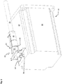
- Figure 1 shows a perspective illustration of a system 10 with a first contact device 20 according to a first embodiment.
- the system 10 has, for example, a component housing 15, the first contact device 20 and a connection line 25.
- an electrical component for example an electric drive motor, can be arranged in the component housing 15.
- the first contact device 20 has a base 30 and a first contact housing 35.
- the base 30 is connected to a side surface 37 of the component housing 15 on a side facing away from the first contact housing 35 on the component housing 15 by means of a fastening means 36, for example screws.
- the connection line 25 is routed parallel to the side surface 37.
- the first contact housing 35 is connected to the base 30 on a side that faces the component housing 15.
- the first contact housing 35 is mounted in the base 30 such that it can rotate about an axis of rotation 40.
- the axis of rotation 40 is oriented perpendicular to the side surface 37.
- the first contact housing 35 On a side facing away from the base 30, the first contact housing 35 has a connection side 45 with which the first contact housing 35 is connected to the connection line 25, in particular to a mating connector 46 arranged on the connection line.
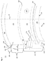
- FIG. 11 shows a detail of a sectional view along a FIG Figure 1 Section plane AA shown through the in Figure 1 System shown 10.
- the first contact housing 35 is designed as an angular housing and is L-shaped in the embodiment.
- the first contact housing 35 has a first housing section 41 and a second housing section 42.
- the first housing section 41 is arranged parallel to the side surface 37 of the component housing 15.
- the second housing section 42 is oriented perpendicular to the first housing section 41 and to the side surface 37 and connected on one side to the first housing section 41.
- the second housing section 42 is connected to the base 30.
- the component housing 15 has a through opening 43.
- the second housing section 42 opens out at the through opening 43 on a side facing away from the first housing section 41.
- the first housing section 41 and essentially the second housing section 42 are designed as a hollow cylinder.
- the first contact housing 35 is preferably formed in one piece and of the same material.
- the first housing section 41 and the second housing section 42 delimit a housing interior 44.
- a plurality of first electrical lines 55 which are each electrically insulated from one another, are arranged in the housing interior 44.
- the first electrical lines 55 are arranged in the housing interior 44 in such a way that the first electrical lines 55 twist by at least 180 ° when the first contact housing 35 is rotated about the axis of rotation 40 and do not block the rotation of the first contact housing 35 or cause damage during the rotation to take.
- the first electrical lines 55 are routed through the through opening 43 into the component housing 15, for example to the component.
- the first contact device 20 has a first contact element 50 on the connection side 45 for each first electrical line 55.
- the first contact element 50 is each connected to an electrical line 55. Furthermore, the first contact element 50 is fastened in the first housing section 41 in the first contact housing 35.
- the connection line 25 has a second contact device 60, for example a mating connector 46, and preferably a plurality of second electrical lines 65.
- the Second contact device 60 has a second contact housing 61 and a second contact element 70 for each second electrical line 65.
- the second contact element 70 is designed to correspond to the first contact element 50 and, in the assembled state of the connection line 25 on the connection side 45 of the first contact device 20, forms an electrical connection with the respectively assigned first contact element 50.
- the second contact element 70 is, for example, designed as a plug contact which engages in the first contact element 50.
- the first contact element 50 can also be designed as a plug contact and the second contact element 70 as a socket contact.
- the second contact element 70 is fastened in the second contact housing 61.
- the second contact housing 61 for example, encompasses the first housing section 41 on the connection side 45 on the circumferential side.
- fastening means and / or latching means can be provided in order to secure the second contact housing 61 against unintentional pulling off from the first contact housing 35.
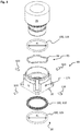
- FIG. 11 shows an exploded view of the FIGS Figures 1 and 2 first contact device 20 shown.
- the first contact device 20 has, in addition to the base 30 and the in Figure 3
- First contact housing 35 shown in abbreviated form has a latching device 90, a clamping device 95 and a sealing device 100.
- the sealing device 100 has a first sealing element 105 second sealing element 110 and a third sealing element 115.
- the first sealing element 105 and the third sealing element 115 are designed, for example, as an O-ring.
- an inner diameter d3 of the third sealing element 115 is greater than an inner diameter d1 of the first sealing element 105.
- the second sealing element 110 preferably has an X-shaped cross section.
- the second sealing element 110 can also be designed differently, for example as an O-ring. Due to the X-shaped configuration of the second sealing element 110, the sealing element 110 seals both in the radial direction and in the axial direction. Furthermore, twisting of the sealing element 100 is avoided. Furthermore, the X-shaped second sealing element 110 has a particularly favorable frictional behavior.
- the tensioning device 95 comprises a corrugated spring 96.
- the corrugated spring 96 is made from a round material and is designed as an open ring.
- Another embodiment of the wave spring 96 would also be conceivable.
- the tensioning device 95 can also have at least one compression spring and / or a plate spring.
- the latching device 90 has at least one latching pin 120.
- four locking pins 120 are provided.
- the number of locking pins 120 can be freely selected. However, it is advantageous if at least three latching pins 120 are provided, which are for example distributed at regular intervals in the circumferential direction relative to the axis of rotation 40.
- FIG. 11 shows a detail of a perspective sectional view along the line in FIG Figure 1 Section plane AA shown through the in Figure 1 base 30 shown.
- the inside of the base 30 is essentially hollow-cylindrical running around the axis of rotation 40 and delimits a base interior 150 on the inside with respect to an environment 151.
- the base 30 has a lower base end face 125 and an upper base end face 130 arranged axially opposite to the axis of rotation 40.
- a circumferential first sealing groove 145 arranged on a first circular path around the axis of rotation 40 is provided on the lower base end face 125.
- the lower base end face 125 of the base 30 rests against the side surface 37 of the component housing 15.
- the first sealing groove 145 is open towards the bottom.
- the first sealing element 105 (in Figure 4 not shown), wherein the first sealing element seals the base interior 150 and the housing interior from the surroundings 151.
- the base 30 has a first base section 141, a second base section 142 and a third base section 143 in the axial direction.
- the first base section 141 adjoins the lower base end face 125.
- the second base section 142 is arranged in the axial direction above directly adjacent to the first base section 141.
- the third base section 143 is arranged adjacent.
- the third base section 143 is arranged in the axial direction between the upper base end face 130 and the second base section 142.
- a first wall thickness w1 is thicker than a second wall thickness w2 of the second base section 142.
- a third wall thickness w3 of the third base section 143 is less than the second wall thickness w2.
- the third base section 143 is made significantly shorter in the axial direction than the first base section 141 and the second base section 142 Direction of the second base section 142 is shorter than the first base section 141.
- an inner base circumferential side 155 has a first shoulder 180.
- the first shoulder 180 has a first support surface 181, which is arranged to run in a plane of rotation relative to the axis of rotation 40.
- the first base section 141 On the inner base circumferential side 155 of the base 30, the first base section 141 has a second sealing groove 160.
- the second sealing groove 160 is open towards the inside towards the base interior 150 and is arranged offset in the axial direction relative to the lower base end face 125.
- the second sealing groove 160 is formed circumferentially around the axis of rotation 40 on a second circular path.
- the second sealing groove 160 like the first sealing groove 145, has a rectangular cross section.
- the first base section 141 has a first recess 175 for each latching pin 120.
- the first recess 175 is designed as a bore and has a recess longitudinal axis 176 which is inclined to the axis of rotation 40, preferably perpendicular to the axis of rotation 40. If several latching pins 120 are provided, the recess longitudinal axes 176 can be arranged in a common plane of rotation with respect to the axis of rotation 40.
- the first recesses 175 can be arranged distributed in the circumferential direction at regular intervals around the circumference.
- the first base section 141 On the inner base circumferential side 155 of the first base section 141, the first base section 141 has a first radial bearing surface 165 of a first radial bearing 170 between the lower base end face 125 and the first recess 175.
- the first radial bearing surface 165 is Here, for example, it is designed to run in a cylindrical manner around the axis of rotation 40.
- a first bevel 185 is provided on the inner base peripheral side 155 of the third base section 143.
- the first bevel 185 has an inclination of approximately 60 ° to 75 ° with respect to the upper base end face 130.
- An outer circumferential side 190 of the base 30 is formed on the first base section 141 to run in a cylindrical manner with respect to the axis of rotation 40.
- the outer base circumferential side 190 is configured in sections in a cylindrical manner on a side facing the first base section 141 and essentially rectangular on a side facing away from the first base section 142.
- the outer base circumferential side 190 is formed on the third base section 143 in the shape of a cylinder around the axis of rotation 40 and is offset radially inward relative to the second base section 142.
- a second shoulder 194 is provided on the outer circumferential side 190 of the base 30 at the transition between the third base section 143 and the second base section 142.
- the second shoulder 194 has a first shoulder surface 195 which runs in a plane of rotation to the axis of rotation 40 and is free on a side facing the upper end face 130 (in the unmounted state of the base 30).
- Figure 5 shows a detail of a side view of the second housing section 42 of the first contact housing 35.
- the second housing section 42 has a second bevel 210 on an outer circumferential housing side 200 adjoining a lower housing end face 205 of the first contact housing 35.
- the second bevel 210 has an inclination of approximately 60 ° to 75 ° with respect to the lower housing end face 205.
- the first radial bearing 170 has a second radial bearing surface 215 axially adjacent to the second bevel 210.
- the second radial bearing surface 215 is designed to correspond to the first radial bearing surface of the base.
- the second radial bearing surface 215 runs in the shape of a cylinder around the axis of rotation 40.
- the latching device 90 On the upper side adjoining the second radial bearing surface 215, the latching device 90 has a latching structure 220 on the outer circumferential side 200 of the housing.
- the latching structure 220 has a disengaging section 225 and a spur toothing 230.
- the spur toothing 230 is arranged in the axial direction between the second radial bearing surface 215 and the unlocking section 225.
- the unlocking section 225 is groove-shaped and is delimited in the axial direction in relation to the axis of rotation 40 on the one hand by the spur toothing 230 and on the other side (on a side facing away from the lower housing face 205) by a groove side surface 235.
- the groove side surface 235 is arranged running in a plane of rotation to the axis of rotation 40.
- a groove base 240 of the unlocking section 225 is designed to run in a cylindrical manner around the axis of rotation 40.
- the unlocking section 225 is open radially outward.
- the spur toothing 230 has at least one first tooth 305 and a second tooth 310 arranged offset in the circumferential direction relative to the first tooth 305.
- the number of teeth 305, 310 of the face gear 230 is in Figure 5 exemplary.
- the spur toothing 230 has a tooth base 315.
- the second housing section 42 has a third shoulder 245, offset in the axial direction relative to the latching structure 220 on a side facing away from the lower housing end face 205 on.
- the third shoulder 245 has a second contact surface 246 which is arranged to run in a plane of rotation relative to the axis of rotation 40.
- the second support surface 246 is in Figure 5 arranged on the side facing the lower housing end face 205.
- a third bevel 250 Adjacent in the axial direction on a side of the second support surface 246 facing away from the lower housing end face 205, a third bevel 250 is additionally provided on the third shoulder 245.
- the third bevel 250 has an inclination of approximately 60 ° to 75 ° with respect to the second support surface 246.
- a second radial bearing 260 has a third radial bearing surface 255.
- the third radial bearing surface 255 is arranged to run in a cylindrical manner around the axis of rotation 40.
- a third sealing groove 265 is provided in the third radial bearing surface 255.
- the third sealing groove 265 is open radially outward.
- a fourth shoulder 270 adjoins the third radial bearing surface 255 on the upper side.
- the outer housing circumferential side 200 of the first contact housing 35 is formed step-like with increasing diameter from the lower housing end face 205 upwards in the direction of the first housing section 41.
- the fourth shoulder 270 has a second shoulder surface 271 on a side facing the lower housing end face 205.
- the second shoulder surface 271 is arranged in a plane of rotation about the axis of rotation 40.
- a second recess 275 is provided in the fourth shoulder 270.
- the second recess 275 is formed in the form of a groove and is formed circumferentially around the axis of rotation 40.
- the second recess 275 is open towards the lower housing end face 205 of the first contact housing 35.
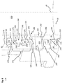
- FIG. 11 shows a detail of a perspective sectional view along the line in FIG Figure 1 Section plane AA shown through the system 10. For reasons of clarity, in Figure 6 only the first contact device 20 is shown.
- the first contact housing 35 is in Figure 6 arranged in a first axial position opposite the base 30.
- the third base section 143 engages the second recess 275 only in sections.
- the second recess 275 and the third base section 143 form a gap seal which, regardless of the axial position of the first contact housing 35 relative to the base 30, prevents dirt particles from penetrating into the base interior 150.
- the second radial bearing 260 has a fourth radial bearing surface 276 on the inner base circumferential side 155 on the second base section 142 axially between the first shoulder 180 and the first bevel 185.
- the fourth radial bearing surface 276 is designed to run cylindrically around the axis of rotation 40 and to correspond to the third radial bearing surface 255.
- the third radial bearing surface 255 rests on the fourth radial bearing surface 276.
- the third sealing element 115 is arranged in the third sealing groove 265.
- the third sealing element 115 rests on the fourth radial bearing surface 276, which in sections also serves as a sealing surface. Due to the high manufacturing quality of the fourth radial bearing surface 276, damage to the third sealing element 115 is avoided in the event of an axial movement of the first contact housing 35 relative to the base 30.
- the first contact device 20 can have a third radial bearing 280.
- the third radial bearing 280 has a fifth radial bearing surface 285 and a sixth radial bearing surface 290.
- the fifth radial bearing surface 285 is arranged on the outer circumferential side 200 of the housing axially between the latching structure 220 and the third shoulder 245.
- the sixth radial bearing surface 290 is arranged on the inner base circumferential side 155.
- the sixth radial bearing surface 290 is arranged in the axial direction between the first shoulder 180 and the recesses 175.
- the sixth radial bearing surface 290 and the fifth radial bearing surface 285 are designed to correspond to one another and run cylindrically around the axis of rotation 40.
- the first radial bearing surface 165 and the sixth radial bearing surface 290 can be designed as a common radial bearing surface.
- the tensioning device 95 is arranged axially between the first shoulder 180 and the third shoulder 245 in a spring chamber 291.
- the ring-shaped spring chamber 291 is delimited radially on the outside by the fourth radial bearing surface 276 and radially on the inside by the fifth radial bearing surface 285.
- the tensioning device 95 is supported on one side on the first support surface 181 and on the other side on the second support surface 246.
- the second sealing element 110 is arranged in the second sealing groove 160. As a result of the arrangement of the second sealing groove 160 on the first radial bearing surface 165, the second sealing element 110 rests on the second radial bearing surface 215, so that damage to the second sealing element 110 can be avoided due to the high surface quality of the first radial bearing 170 designed as a plain bearing.
- the second radial bearing surface 215 rests against the first radial bearing surface 165. Due to the radial bearings 170, 260, 280, which are designed as plain bearings, and the flat contact between the respective associated radial bearing surfaces 165, 215, 255, 276, 285, 290, high forces acting transversely to the axis of rotation 40, which can cause tilting of the second housing section 42 in to the Can cause base interior 150 can be reliably avoided.
- levering or destruction of the first contact housing 35 is reliably avoided via the radial bearings 170, 260, 280 even when high forces act perpendicular to the axis of rotation 40 on the second housing section 42 due to the large axial distance between the radial bearings 170, 260, 280.
- the second housing section 42 Providing the bevels 185, 210, 250 enables the second housing section 42 to be pushed into the base interior 150 particularly easily from above in the direction of the component housing.
- the first bevel 185 prevents squeezing and / or damage to the third sealing element 115
- the second bevel 210 prevents squeezing and / or damage to the second sealing element 110 when the second housing section 42 is pushed axially into the base interior 150. This ensures reliable sealing of the base interior 150 by the second and third sealing elements 110, 115 between the base 30 and the second housing section 42.
- the arrangement of the locking device 90 axially between the second sealing element 110 and the third sealing element 115 reliably prevents contamination or fluids from penetrating into the component housing 15.
- the penetration of possibly broken parts, for example the spur toothing 230, through the second and third sealing elements 110, 115 into the component housing 15 as well as abrasion due to wear of the latching device 90 and thus possible damage to the components arranged in the component housing 15 is also prevented.
- the latching pin 120 has a first pin section 295 and a second pin section 300.
- the first pin portion 295 is connected to the second pin portion 300.
- the Latching pin 120 is cylindrical, the outer diameter extending over the entire length of the latching pin 120.
- the locking pin 120 can be chamfered on the front side.
- the first pin section 295 engages in the first recess 175 of the base 30. It is particularly advantageous here if the first pin section 295 is pressed into the first recess 175. As a result, a reliable hold of the locking pin 120 in the base 30 can be ensured.
- a different type of fastening of the locking pin 120 to the base 30 is also conceivable, so the locking pin 120 can also be connected to the base 30 in a force-locking and / or form-locking and / or material-locking manner.
- the second pin section 300 protrudes into the base interior 150. In the first axial position, as in FIG Figure 6 As shown, the second pin section 300 engages in the spur toothing 230 and secures a position of the first contact housing 35 in the circumferential direction in relation to the axis of rotation 40.
- the system 10 described above is particularly easy and quick to assemble.
- the contact device 20 can also be mounted (partially) automatically.
- the assembly of the system 10 is briefly discussed below, although it is of course possible to deviate from the sequence described below.
- the second sealing element 110 is inserted into the second sealing groove 160.
- the clamping device 95 is introduced into the base interior 150 from above and placed on the first support surface 181.
- the third sealing element 115 is introduced into the third sealing groove 265.
- the first contact housing 35 is then pushed into the base interior 150 until the unlocking section 225 is arranged at the level of the recesses 175.
- the locking pins 120 are then pushed into the recesses 175 and, if necessary, glued.
- the first sealing element 105 is then inserted into the first sealing groove 105 and the first electrical line 55 is threaded through the through opening to the electrical drive motor.
- the base 30 is placed on the side surface 37 and fastened to the component housing 15 by means of the fastening means.
- the electrical line is connected to the first contact element and the first contact element is attached to the connection side of the first contact housing 35.
- FIG. 11 shows a detail of a sectional view along a FIG Figure 1 Section plane BB shown through the first contact device 20.
- the first tooth 305 has a first tooth flank 320 on a side facing the second tooth 310 and the second tooth 310 has a second tooth flank 325 on a side facing the first tooth 305.
- the tooth base 315 connects the first tooth flank 320 with the second tooth flank 325.
- the first tooth flank 320 is delimited by a tooth tip 335 and the tooth base 315.
- the tooth head 335 is arranged on a side of the tooth 305, 310 facing the unlocking section 225 and delimits the unlocking section 225 opposite the groove side surface 235.
- Each tooth 305, 310 has a tooth base 340.
- the tooth base 340 is arranged on a side of the tooth 305, 310 facing away from the unlatching section 225.
- the first tooth flank 320 and the second tooth flank 325 are oriented obliquely to the axis of rotation 40, in particular obliquely to a plane in which the axis of rotation 40 runs.
- the first tooth flank 320 and the second tooth flank 325 can also be aligned parallel to one another, each of the tooth flanks 320, 325 being arranged in a common plane with the axis of rotation 40.
- first tooth flank 320, the tooth base 315 and the second tooth flank 325 are arranged on a common arc, in particular on a common circular path with a center point 330.
- the center point 330 can be arranged in the unlatching section 225.
- the center point 330 can also be arranged outside the unlocking section 225, for example on a side of the unlocking section 225 facing away from the spur toothing 230 in the axial direction.
- the first tooth flank 320 forms an angle ⁇ with the second tooth flank 325 at the tooth tip 335. It is particularly advantageous if the angle ⁇ is an acute or an obtuse angle. It is also advantageous if the angle ⁇ is in a range from 0 ° to 170 °, in particular in a range from 30 ° to 90 °. The angle is advantageously 60 °.
- the second pin section 300 has a contact surface 345 on a side facing the face toothing 230.
- the contact surface 345 is, for example, cylindrical and is designed to correspond to the first tooth flank 320, the tooth base 315 and the second tooth flank 325.
- the unlocking section 225 has an axial width in the axial direction between the tooth tip 335 and the groove side surface 235 which corresponds approximately to an axial extension of the second pin section 300, in the embodiment a diameter of the second pin section 300.
- the contact surface 345 is in the first axial position, as shown in FIG Figure 7 is shown, on the first tooth flank 320, the second tooth flank 325 and the tooth base 315, so that a position in the circumferential direction of the first contact housing 35 is set relative to base 30. Furthermore, because the contact surface 345 rests on the tooth base 315, undesired axial movement of the first contact housing 35 with respect to the axis of rotation 40 relative to the base 30 is avoided. Alternatively, it is also conceivable that the contact surface 345 also only rests exclusively on one of the tooth flanks 320, 325 or exclusively only on the tooth base 315 and is arranged at a distance from the tooth flanks 320, 325.
- the tensioning device 95 is relaxed in the first axial position.
- the tensioning device 95 can be pretensioned in the first axial position.
- the preload has the advantage that if, for example, the contact surface 345 only rests against the tooth base 315, the preload between the contact surface 345 and the tooth base 315 creates a frictional connection and so in the circumferential direction the first contact housing 35 only after overcoming the frictional connection around the axis of rotation 40 can be twisted.
- the tensioning device 95 provides a first axial force F A1 in the first axial position.
- the first axial force F A1 is introduced into the first contact housing 35 through the third shoulder 245.
- the first axial force F A1 acts, for example, in an upward direction.
- the spur toothing 230 is pulled upwards and pressed against the contact surface 345 with the first axial force F A1.
- This configuration has the advantage that the first contact housing 35 is arranged without play relative to the base 30 in the axial direction.
- FIG. 13 shows a sectional view along the line in FIG Figure 1 Section plane AA shown through the in Figure 1 shown first contact device 20, wherein the first contact housing 35 is arranged in a second axial position.
- the first contact housing 35 is shifted downward in the direction of the component housing 15.
- the locking pin 120 does not engage in the face toothing 230, but rather engages in the unlocking section 225.
- the unlocking section 225 is designed as a ring-shaped circumferential groove, so that a movement of the first contact housing 35 relative to the base 30 around the axis of rotation 40 and the second axial position is released in the circumferential direction and, as a result, for example, the first housing section can be aligned in such a way that the connection line, but at least the second contact device and the first housing section are aligned with one another.
- the second housing section 42 protrudes into the through opening 43.
- the unlatching of the latching device 90 for transferring the first contact housing 35 from the first axial position into the second axial position can take place in two possible variants.
- the first contact housing 35 by a user of the system on the upper side to the first terminal housings 35 are pushed with a second axial force F A2, wherein by means of the second axial force F A2, the first contact housing 35 relative to the base 30 first from the relatively against the action of the clamping device 95 Axial position (cf. Figure 7 ) into the second axial position (cf. Figure 8 ) is transferred until the locking pin 120 only engages in the unlatching section 225 and is thus arranged outside of the spur toothing 230. If the second axial force F A2 is maintained, the first contact housing 35 can be rotated relative to the base 30 about the axis of rotation 40.
- the axial displacement of the first contact housing 35 with respect to the base 30 is limited in the embodiment by the fact that the second pin section 300 strikes the groove side surface 235 on a side facing away from the spur toothing 230. This prevents the tensioning device 90 from being overpressed.
- the second shoulder surface 271 can also strike the first shoulder surface 195 and thus limit the movement of the first contact housing 35 in the direction of the base 30 or the component housing 15.
- the tensioning device 95 is tensioned in the second axial position and provides a third axial force F A3 which acts against the second axial force F A2. If the second axial force F A2 is canceled after the first contact housing 35 has been rotated, the third axial force F A3 promotes the first contact housing 35 from the second axial position back into the first axial position.
- the second pin section snaps into place between two teeth.
- a torque M about the axis of rotation 40 is introduced into the first contact device 20 by the user in order to rotate the first contact housing 35 with respect to the base 30. Due to the inclined alignment of the first tooth flank 320 and the contact surface 345 corresponding to the first tooth flank 320, the torque M effects a conversion of part of the torque M into the second axial force F A2 .
- the second axial force F A2 acts against the third axial force F A3 , and if the second axial force F A2 is greater than the third axial force F A3 , the first tooth flank slides on the contact surface 345 of the locking pin 120 while the first contact housing 35 is rotated .
- the spur toothing 230 or the first contact housing 35 is moved from the first axial position into the second axial position by the second axial force F A2 in the direction of the component housing 15 postponed. If the second pin section 300 slides over the tooth head, the first contact housing 35 is in the second axial position.
- the tensioning device returning the first contact housing 35 to the first axial position with the second axial force F A2 until the second pin section 300 is arranged centrally between the teeth. If the torque M is further maintained, the described snapping axial movement is repeated between the first axial position and the second axial position until the first contact section branches off in the desired direction. The first lines are twisted within the first contact housing 35.
- the first contact device 20 can have an anti-rotation device which is designed to allow only a rotation of the first contact housing 35 by a predefined further angle, for example 350 °, in order to allow the axis of rotation 40 with respect to the base 30. This ensures that the first electrical line is not twisted too much in the first contact device 20.
- the second variant has the advantage that the user is additionally provided with a haptic feeling when rotating the first contact device 20, by means of which the user is informed that the locking pin 120 has engaged after the torque M has been provided between the teeth. Furthermore, the first contact housing 35 can be rotated about the axis of rotation 40 even if the installation space is restricted.
- FIG. 13 shows a sectional view along a line in FIG Figure 1 Section plane CC shown through the in Figure 1 first contact device 20 shown.
- the spur toothing 230 has a tooth pitch which is selected such that in the first axial position all of the latching pins 120 engage in the spur toothing 230. Furthermore, even when the torque M is introduced about the axis of rotation 40 into the first contact housing 35, only one tooth flank 320, 325 of the spur toothing 230 is constantly loaded and the other tooth flanks 320, 325 of the spur toothing 230 are unloaded. This avoids uneven wear of the spur toothing 230 and of the latching pin 120.
- the distance between two locking pins 120 which is selected uniformly in the circumferential direction, in the embodiment the locking pins 120 are each arranged at a 90 ° angle to one another, furthermore ensures that when the first contact housing 35 is transferred from the first axial position to the second axial position and from the second axial position back into the first axial position, the first contact housing 35 is not tilted in the base interior 150 and / or at least one of the radial bearings is overstressed.
- a fastening opening 350 can be provided laterally on the outer base circumferential side 190 in a corner area of the first base section 141 in order to releasably fasten the base 30 to the component housing by means of the fastening means, for example a screw connection, and to press the first sealing element against the side surface.
- FIG. 11 shows a detail of a sectional view along the line in FIG Figure 1 according to a first embodiment shown section plane BB through a first contact device 20 according to a second embodiment.
- the first contact device 20 is essentially identical to that in FIG Figures 1 to 9 first contact device shown.
- the first tooth flank 320 axially abuts the second tooth flank 325 directly on a side of the teeth 305, 310 facing away from the unlatching section 225.
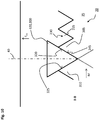
- the tooth 305, 310 has an exemplary triangular cross section.
- the tooth flank 320, 325 and the respectively corresponding contact surface 345 are each arranged in a plane which is inclined to the plane in which the axis of rotation 40 runs.
- the tooth flank 320, 325 and the contact surface 345 are each designed to correspond to one another and are designed to be planar in the embodiment.
- the latching pin 120 has a triangular, preferably an isosceles triangular, cross section at least in the second pin section 300.
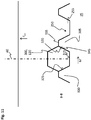
- FIG. 13 shows a sectional view along the line in FIG Figure 1 Section plane BB shown through a first contact device 20 according to a third embodiment.
- the first contact device 20 is essentially a combination of that in FIG Figure 10 and the one in the Figures 1 to 9 shown first contact device.
- the latching pin 120 is polygonal at least in the second pin section 300.
- the polygonal cross section can also extend over the entire extent of the locking pin 120.
- the recess into which the first pin section engages would also have a polygonal design corresponding to the polygonal configuration of the latching pin 120.
- the spur toothing 230 is designed in such a way that the Tooth head 335 is planar to delimit the unlocking section 225 and runs in a plane of rotation to the axis of rotation 40.
- the tooth flanks 320, 325 and the contact surface 345 provided to correspond to the tooth flank 320, 325 are designed to be planar.
- the tooth flank 320, 325 could also be convex or concave and the respective corresponding contact surface 345 could be concave or convex.
- the tooth base 315 is provided.
- the second pin section 300 also rests against the tooth base 315 with the contact surface 345 and against the tooth flanks 320, 325. It would also be conceivable that the tooth base 315 is arranged at a distance from the contact surface 345.
Landscapes
- Details Of Connecting Devices For Male And Female Coupling (AREA)
- Regulating Braking Force (AREA)
- Rotary Pumps (AREA)
- Sealing Devices (AREA)
Claims (15)
- Dispositif de contact (20),- comprenant un boîtier de contact (35), une base (30), un dispositif de serrage (95) et un dispositif d'encliquetage (90),- la base (30) délimitant un espace intérieur de base (150),- le boîtier de contact (35) venant en prise au moins dans certaines parties dans l'espace intérieur de base (150),- le dispositif d'encliquetage (90) comprenant, au niveau d'un côté périphérique de boîtier extérieur (200) du boîtier de contact (35), une structure d'encliquetage (220) et au moins une goupille d'encliquetage (120),- la structure d'encliquetage (220) comprenant une denture frontale (230) et une partie de désencliquetage (225) adjacente à la denture frontale (230) dans la direction axiale,- la partie de désencliquetage (225) étant réalisée en forme de rainure de manière à s'étendre autour du boîtier de contact (35) au moins dans certaines parties dans la direction périphérique,- la goupille d'encliquetage (120) étant reliée à la base (30) et pénétrant dans l'espace intérieur de base (150),- le dispositif de serrage (95) étant disposé entre la base (30) et le boîtier de contact (35) dans l'espace intérieur de base (150),- le boîtier de contact (35) étant déplaçable par rapport à la base (30) entre une première position axiale et une deuxième position axiale dans la direction axiale à l'encontre de l'action du dispositif de serrage (95),- dans la première position axiale, la goupille d'encliquetage (120) venant en prise dans la denture frontale (230) et fixant une position du boîtier de contact (35) par rapport à la base (30) dans la direction périphérique,- dans la deuxième position axiale, la goupille d'encliquetage (120) venant en prise dans la partie de désencliquetage (225) et le boîtier de contact (35) pouvant tourner autour d'un axe de rotation (40) par rapport à la base (30) dans la direction périphérique,- dans la deuxième position axiale, le dispositif de serrage (95) produisant une force axiale (FA3) pour ramener le boîtier de contact (35) à la première position axiale.
- Dispositif de contact (20) selon la revendication 1,- la denture frontale (230) comprenant au moins une première dent (305) et une deuxième dent (310),- la première dent (305) étant disposée de manière espacée de la deuxième dent (310) dans la direction périphérique,- la denture frontale (230) comprenant un fond de dent (315) entre les dents (305, 310),- la goupille d'encliquetage (120) comprenant une partie de goupille (300),- la partie de goupille (300) étant disposée dans l'espace intérieur de base (150) et comprenant une surface d'appui (345) sur un côté tourné vers la denture frontale (230) du côté périphérique,- dans la première position axiale, la surface d'appui (345) s'appuyant sur le fond de dent (315) au moins dans certaines parties, ou- dans la première position axiale, la surface d'appui (345) étant disposée de manière espacée du fond de dent (315) .
- Dispositif de contact selon la revendication 1 ou 2,- la denture frontale (230) comprenant au moins une première dent (305) présentant un premier flanc de dent (320),- la goupille d'encliquetage (120) comprenant une partie de goupille (300),- la partie de goupille (300) étant disposée dans l'espace intérieur de base (150) et comprenant une surface d'appui (345) sur le côté tourné vers la denture frontale (230) du côté périphérique,- le premier flanc de dent (320) étant orienté de manière inclinée en biais au moins dans certaines parties par rapport à un plan dans lequel l'axe de rotation (40) s'étend,- ou le premier flanc de dent (320) et l'axe de rotation (40) étant orientés de manière à s'étendre parallèlement l'un à l'autre,- dans la première position axiale, la surface d'appui (345) s'appuyant contre le premier flanc de dent (320).
- Dispositif de contact selon la revendication 3,- le premier flanc de dent (320) étant orienté de telle sorte qu'en coopération avec la surface d'appui (345), en cas de rotation du boîtier de contact (35) par rapport à la base (30) autour de l'axe de rotation (40) par un mouvement de glissement du premier flanc de dent (320) sur la surface d'appui (345), un déplacement axial du boîtier de contact (35) de la première position axiale à la deuxième position axiale est provoqué.
- Dispositif de contact (20) selon l'une des revendications 2 à 4,- la première dent (305) comprenant une tête de dent (335) et un pied de dent (340),- la partie de désencliquetage (225) étant délimitée par la tête de dent (335) dans la direction axiale au niveau d'un premier côté axial et le pied de dent (340) étant disposé sur un côté de la première dent (305) opposé à la partie de désencliquetage (225),- la partie de désencliquetage (225) étant délimitée par une surface latérale de rainure (235) au niveau d'un deuxième côté axial opposé au premier côté axial dans la direction axiale,- la surface latérale de rainure (235) étant disposée dans un premier plan de rotation par rapport à l'axe de rotation (40).
- Dispositif de contact (20) selon l'une des revendications 2 à 5,- la surface d'appui (345) de la partie de goupille (300) étant réalisée de manière arquée et/ou plane et/ou polygonale et/ou concave et/ou convexe en section transversale au moins dans certaines parties.
- Dispositif de contact (20) selon l'une des revendications 2 à 6,- la deuxième dent (310) comprenant un deuxième flanc de dent (325) sur un côté tourné vers la première dent (305),- dans la première position axiale, la surface d'appui (345) s'appuyant contre le premier flanc de dent (320) et contre le deuxième flanc de dent (325).
- Dispositif de contact (20) selon la revendication 7,- le premier flanc de dent (320), le fond de dent (315) et le deuxième flanc de dent (325) étant disposés sur un arc commun, en particulier sur une trajectoire circulaire commune, présentant un centre (330),- le centre (330) étant disposé dans la partie de désencliquetage (225),
ou- le centre (330) étant disposé à l'extérieur de la partie de désencliquetage (225),- le centre (330) étant disposé de préférence sur un côté de la partie de désencliquetage (225) opposé à la denture frontale (230). - Dispositif de contact (20) selon la revendication 7 ou 8,- le premier flanc de dent (320) et le deuxième flanc de dent (325) étant orientés parallèlement l'un à l'autre,- ou- le premier flanc de dent (320) formant par rapport au deuxième flanc de dent (325) un angle (α),- l'angle (a) étant un angle obtus ou un angle aigu, ou- le premier flanc de dent (320) formant par rapport au deuxième flanc de dent (325) un angle (α),- l'angle (a) étant compris dans une plage de 0° à 170°,
ou- le premier flanc de dent (320) formant par rapport au deuxième flanc de dent (325) un angle (α),- l'angle (a) étant compris dans une plage de 30° à 90°,
ou- le premier flanc de dent (320) formant par rapport au deuxième flanc de dent (325) un angle (α),- l'angle valant 60°. - Dispositif de contact (20) selon l'une des revendications précédentes,- dans la première position axiale, le dispositif de serrage (95) étant relâché,
ou- dans la première position axiale, le dispositif de serrage (95) étant précontraint et pressant la denture frontale (230) contre la surface d'appui (345) par une autre force axiale (FA1). - Dispositif de contact selon l'une des revendications précédentes,- le dispositif de serrage (95) comportant au moins une rondelle ressort et/ou un ressort ondulé et/ou un ressort de compression,- la base (30) comprenant un premier épaulement (180) sur un côté tourné vers l'espace intérieur de base (150) et le boîtier de contact (35) comprenant un deuxième épaulement (245) disposé radialement du côté extérieur,- le dispositif de serrage (95) étant disposé axialement entre le premier épaulement (180) et le deuxième épaulement (245),- le dispositif de serrage (95) étant supporté sur le premier épaulement (180) au niveau d'un côté et étant supporté sur le deuxième épaulement (245) au niveau de l'autre côté.
- Dispositif de contact (20) selon l'une des revendications précédentes,- la base (30) comprenant au moins un évidement (175),- l'évidement (175) étant disposé de manière inclinée par rapport à l'axe de rotation (40), de préférence dans un deuxième plan de rotation par rapport à l'axe de rotation (40),- la goupille d'encliquetage (120) comportant une autre partie de goupille (295),- l'autre partie de goupille (295) venant en prise dans l'évidement (175) au moins dans certaines parties,- l'autre partie de goupille (295) étant reliée à la base (30) par force et/ou par complémentarité de forme et/ou par liaison de matière,- l'autre partie de goupille (295) étant pressée de préférence dans l'évidement (175),- et/ou- le boîtier de contact (35) comportant une première partie de boîtier (41) et une deuxième partie de boîtier (42) reliée à la première partie de boîtier (41),- la deuxième partie de boîtier (42) étant disposée au moins partiellement dans l'espace intérieur de base (150) et la première partie de boîtier (41) étant disposée à l'extérieur de l'espace intérieur de base (150),- la première partie de boîtier (41) étant disposée de manière inclinée, de préférence perpendiculairement, par rapport à la deuxième partie de boîtier (42),- la première partie de boîtier (41) et la deuxième partie de boîtier (42) étant reliées l'une à l'autre par complémentarité de forme et/ou par liaison de matière et/ou par force, ou la première partie de boîtier (41) et la deuxième partie de boîtier (42) étant réalisées d'une seule pièce et de manière venue de matière.
- Dispositif de contact (20) selon l'une des revendications précédentes,- comprenant un premier palier radial (170),- le premier palier radial (170) comprenant une première surface de palier radial (165) au niveau d'un côté périphérique de base intérieur (155) de la base (30) axialement entre un côté frontal de base inférieur (125) et la goupille d'encliquetage (120),- le premier palier radial (170) comprenant une deuxième surface de palier radial (215) réalisée de manière correspondante à la première surface de palier radial (165) au niveau du côté périphérique de boîtier extérieur (200) du boîtier de contact (35) axialement entre un côté frontal de boîtier inférieur (205) du boîtier de contact (35) et la structure d'encliquetage (220),- la première surface de palier radial (165) et la deuxième surface de palier radial (215) étant réalisées de manière à s'étendre de préférence de manière circulaire autour de l'axe de rotation (40),- la deuxième surface de palier radial (215) étant supportée sur la première surface de palier radial (165).
- Dispositif de contact (20) selon la revendication 13,- comprenant un deuxième palier radial (260),- le deuxième palier radial (260) étant disposé de manière axialement opposée par rapport au premier palier radial (170),- le deuxième palier radial (260) comprenant une troisième surface de palier radial (255) au niveau du côté périphérique de boîtier extérieur (200) du boîtier de contact (35),- le deuxième palier radial (260) comprenant une quatrième surface de palier radial (276) disposée axialement entre un côté frontal de base supérieur (130) opposé au côté frontal de base inférieur (125) et la goupille d'encliquetage (120) au niveau du côté périphérique de base intérieur (155) de la base (30),- la troisième surface de palier radial (255) et la quatrième surface de palier radial (276) étant réalisées de manière à s'étendre autour de l'axe de rotation (40),- la troisième surface de palier radial (255) étant supportée sur la quatrième surface de palier radial (276),- le premier palier radial (170) étant réalisé de préférence de manière plus étroite que le deuxième palier radial (260) dans la direction radiale.
- Dispositif de contact (20) selon la revendication 13 ou 14,- comprenant un dispositif d'étanchéité présentant au moins un élément d'étanchéité (110),- l'élément d'étanchéité (110) étant disposé axialement entre la goupille d'encliquetage (120) et le côté frontal de base inférieur (125),- l'élément d'étanchéité (110) étant disposé entre la base (30) et le boîtier de contact (35) dans la direction radiale,- l'élément d'étanchéité (110) réalisant l'étanchéité fluidique de l'espace intérieur de base (150) par rapport à un environnement (151),- l'élément d'étanchéité (110) présentant de préférence une section transversale en forme de X ou étant réalisé comme un joint torique.
Applications Claiming Priority (2)
| Application Number | Priority Date | Filing Date | Title |
|---|---|---|---|
| DE102017120059.2A DE102017120059B3 (de) | 2017-08-31 | 2017-08-31 | Kontakteinrichtung |
| PCT/EP2018/073005 WO2019042927A1 (fr) | 2017-08-31 | 2018-08-27 | Dispositif de contact |
Publications (3)
| Publication Number | Publication Date |
|---|---|
| EP3659217A1 EP3659217A1 (fr) | 2020-06-03 |
| EP3659217B1 true EP3659217B1 (fr) | 2021-08-18 |
| EP3659217B8 EP3659217B8 (fr) | 2021-09-29 |
Family
ID=63517851
Family Applications (1)
| Application Number | Title | Priority Date | Filing Date |
|---|---|---|---|
| EP18765579.0A Active EP3659217B8 (fr) | 2017-08-31 | 2018-08-27 | Dispositif de contact |
Country Status (5)
| Country | Link |
|---|---|
| US (1) | US10741962B2 (fr) |
| EP (1) | EP3659217B8 (fr) |
| CN (1) | CN111247698B (fr) |
| DE (1) | DE102017120059B3 (fr) |
| WO (1) | WO2019042927A1 (fr) |
Families Citing this family (2)
| Publication number | Priority date | Publication date | Assignee | Title |
|---|---|---|---|---|
| WO2019034203A1 (fr) * | 2017-08-18 | 2019-02-21 | Harting Electric Gmbh & Co. Kg | Mécanisme de verrouillage pour boîtier de connecteur |
| DE102019127442A1 (de) | 2019-10-11 | 2021-04-15 | Herbert Waldmann Gmbh & Co Kg | Leuchte mit Steckkontakt, Verwendung einer solchen Leuchte und Steckverbinder für eine solche Leuchte |
Family Cites Families (10)
| Publication number | Priority date | Publication date | Assignee | Title |
|---|---|---|---|---|
| US4820184A (en) * | 1987-10-05 | 1989-04-11 | Interconnection Products Incorporated | Electrical connector retaining ratchet |
| US5085479A (en) * | 1988-11-28 | 1992-02-04 | Taylor William T | Vertically manipulated ratchet fishing tool |
| US20060079109A1 (en) * | 2004-10-04 | 2006-04-13 | Neal Castleman | Quick-disconnect threaded connector |
| FR2997800B1 (fr) * | 2012-11-06 | 2015-01-30 | Souriau | Systeme de verrouillage securise et connecteur comportant un tel systeme |
| DE102013007899B4 (de) * | 2013-05-07 | 2017-12-14 | Yamaichi Electronics Deutschland Gmbh | Schwenkbarer Verbinder und Verwendung |
| TWM491981U (zh) * | 2014-08-12 | 2014-12-11 | Well Shin Technology Co Ltd | 線纜連接器 |
| DE202015102170U1 (de) | 2015-04-30 | 2015-05-13 | Intercontec Pfeiffer Industrie-Steckverbindungen Gmbh | Elektrischer Winkelstecker mit Stützring und Verrastring einer Gegenlagerung für ein Federelement |
| US9666973B1 (en) * | 2016-06-10 | 2017-05-30 | Amphenol Corporation | Self-locking connector coupling |
| US10756482B2 (en) * | 2016-09-20 | 2020-08-25 | Itt Manufacturing Enterprises Llc | Torque-limiting couplings |
| CN106299856B (zh) * | 2016-09-30 | 2018-08-10 | 中航光电科技股份有限公司 | 一种新型可快速锁紧及解锁的连接器 |
-
2017
- 2017-08-31 DE DE102017120059.2A patent/DE102017120059B3/de active Active
-
2018
- 2018-08-27 CN CN201880068397.4A patent/CN111247698B/zh active Active
- 2018-08-27 EP EP18765579.0A patent/EP3659217B8/fr active Active
- 2018-08-27 WO PCT/EP2018/073005 patent/WO2019042927A1/fr not_active Ceased
-
2020
- 2020-02-27 US US16/802,945 patent/US10741962B2/en active Active
Non-Patent Citations (1)
| Title |
|---|
| None * |
Also Published As
| Publication number | Publication date |
|---|---|
| US20200194923A1 (en) | 2020-06-18 |
| DE102017120059B3 (de) | 2018-12-13 |
| US10741962B2 (en) | 2020-08-11 |
| CN111247698B (zh) | 2021-08-03 |
| CN111247698A (zh) | 2020-06-05 |
| EP3659217B8 (fr) | 2021-09-29 |
| EP3659217A1 (fr) | 2020-06-03 |
| WO2019042927A1 (fr) | 2019-03-07 |
Similar Documents
| Publication | Publication Date | Title |
|---|---|---|
| DE19839342C2 (de) | Gerätesteckverbinder | |
| EP1851830B1 (fr) | Systeme de liaison, notamment systeme de connexion electrique | |
| EP2851596B1 (fr) | Élément de traversée murale pour une conduite de fluide et traversée murale | |
| EP3776750B1 (fr) | Pièce de connecteur électrique et système de connexion électrique avec verrouillage | |
| EP2500587A1 (fr) | Dispositif de fixation destiné à l'agencement sur un rail de montage | |
| DE102004017275A1 (de) | Abgedichtete Steckverbindung durch eine Trennwand und Montageverfahren | |
| EP2593994A1 (fr) | Boîtier, en particulier pour un connecteur de câble électrique | |
| EP1062986B1 (fr) | Appareil éléctronique implantable avec connecteur et verrouillage | |
| EP2495823B1 (fr) | Système de liaison d'un boîtier d'un connecteur à fiches avec un écrou | |
| EP3659217B1 (fr) | Dispositif de contact | |
| DE102016124805B4 (de) | Membranventil | |
| DE102020110647A1 (de) | Primärverriegelung | |
| WO2009115080A2 (fr) | Dispositif permettant de réaliser une connexion électrique sèche d'une serrure de véhicule automobile | |
| EP4010601B1 (fr) | Élément de verrouillage pour verrouiller de manière libérable un mouvement de rotation d'un adaptateur par rapport à un corps d'une tige de traction-compression et tige de traction-compression pourvue d'un tel élément de verrouillage | |
| DE10247185B4 (de) | Vorrichtung zum Einstellen des Spiels einer Welle | |
| EP2064454B1 (fr) | Dispositif de fixation | |
| WO2021089462A1 (fr) | Partie de connexion enfichable dotée d'un dispositif de mise en prise | |
| EP4496135A1 (fr) | Connecteur à enveloppe mobile | |
| DE202019104173U1 (de) | Vorrichtung zum Befestigen eines ersten Bauteils an einem zweiten Bauteil | |
| DE102008027510B4 (de) | Vorrichtung zur Befestigung zweier Komponenten einer für eine Stelleinrichtung vorgesehenen Antriebseinheit, insbesondere für einen Fensterheberantrieb, an einem tragenden Strukturelement eines Kraftfahrzeugs | |
| EP4036355A1 (fr) | Dispositif actionneur, cylindre de fermeture, système et procédé de verrouillage | |
| DE102010034630A1 (de) | Elektrische Steckverbindung | |
| EP3404777B1 (fr) | Raccordement d'appareil | |
| EP3314137A1 (fr) | Dispositif d'accouplement et système de clapet pour installation d'alimentation en air frais comprenant un dispositif d'accouplement | |
| DE4413001A1 (de) | Elektrische Verbindungsvorrichtung |
Legal Events
| Date | Code | Title | Description |
|---|---|---|---|
| STAA | Information on the status of an ep patent application or granted ep patent |
Free format text: STATUS: UNKNOWN |
|
| STAA | Information on the status of an ep patent application or granted ep patent |
Free format text: STATUS: THE INTERNATIONAL PUBLICATION HAS BEEN MADE |
|
| PUAI | Public reference made under article 153(3) epc to a published international application that has entered the european phase |
Free format text: ORIGINAL CODE: 0009012 |
|
| STAA | Information on the status of an ep patent application or granted ep patent |
Free format text: STATUS: REQUEST FOR EXAMINATION WAS MADE |
|
| 17P | Request for examination filed |
Effective date: 20200228 |
|
| AK | Designated contracting states |
Kind code of ref document: A1 Designated state(s): AL AT BE BG CH CY CZ DE DK EE ES FI FR GB GR HR HU IE IS IT LI LT LU LV MC MK MT NL NO PL PT RO RS SE SI SK SM TR |
|
| AX | Request for extension of the european patent |
Extension state: BA ME |
|
| STAA | Information on the status of an ep patent application or granted ep patent |
Free format text: STATUS: EXAMINATION IS IN PROGRESS |
|
| 17Q | First examination report despatched |
Effective date: 20200630 |
|
| DAV | Request for validation of the european patent (deleted) | ||
| DAX | Request for extension of the european patent (deleted) | ||
| GRAP | Despatch of communication of intention to grant a patent |
Free format text: ORIGINAL CODE: EPIDOSNIGR1 |
|
| STAA | Information on the status of an ep patent application or granted ep patent |
Free format text: STATUS: GRANT OF PATENT IS INTENDED |
|
| INTG | Intention to grant announced |
Effective date: 20210301 |
|
| GRAS | Grant fee paid |
Free format text: ORIGINAL CODE: EPIDOSNIGR3 |
|
| GRAA | (expected) grant |
Free format text: ORIGINAL CODE: 0009210 |
|
| STAA | Information on the status of an ep patent application or granted ep patent |
Free format text: STATUS: THE PATENT HAS BEEN GRANTED |
|
| REG | Reference to a national code |
Ref country code: DE Ref legal event code: R108 Ref document number: 502018006666 Country of ref document: DE |
|
| AK | Designated contracting states |
Kind code of ref document: B1 Designated state(s): AL AT BE BG CH CY CZ DE DK EE ES FI FR GB GR HR HU IE IS IT LI LT LU LV MC MK MT NL NO PL PT RO RS SE SI SK SM TR |
|
| REG | Reference to a national code |
Ref country code: GB Ref legal event code: FG4D Free format text: NOT ENGLISH |
|
| REG | Reference to a national code |
Ref country code: CH Ref legal event code: EP |
|
| REG | Reference to a national code |
Ref country code: CH Ref legal event code: PK Free format text: BERICHTIGUNG B8 Ref country code: IE Ref legal event code: FG4D Free format text: LANGUAGE OF EP DOCUMENT: GERMAN Ref country code: AT Ref legal event code: REF Ref document number: 1422473 Country of ref document: AT Kind code of ref document: T Effective date: 20210915 |
|
| RBV | Designated contracting states (corrected) |
Designated state(s): AL AT BE BG CH CY CZ DK EE ES FI FR GB GR HR HU IE IS IT LI LT LU LV MC MK MT NL NO PL PT RO RS SE SI SK SM TR |
|
| REG | Reference to a national code |
Ref country code: DE Ref legal event code: R107 Ref document number: 502018006666 Country of ref document: DE |
|
| REG | Reference to a national code |
Ref country code: LT Ref legal event code: MG9D |
|
| REG | Reference to a national code |
Ref country code: NL Ref legal event code: MP Effective date: 20210818 |
|
| PG25 | Lapsed in a contracting state [announced via postgrant information from national office to epo] |
Ref country code: HR Free format text: LAPSE BECAUSE OF FAILURE TO SUBMIT A TRANSLATION OF THE DESCRIPTION OR TO PAY THE FEE WITHIN THE PRESCRIBED TIME-LIMIT Effective date: 20210818 Ref country code: ES Free format text: LAPSE BECAUSE OF FAILURE TO SUBMIT A TRANSLATION OF THE DESCRIPTION OR TO PAY THE FEE WITHIN THE PRESCRIBED TIME-LIMIT Effective date: 20210818 Ref country code: FI Free format text: LAPSE BECAUSE OF FAILURE TO SUBMIT A TRANSLATION OF THE DESCRIPTION OR TO PAY THE FEE WITHIN THE PRESCRIBED TIME-LIMIT Effective date: 20210818 Ref country code: RS Free format text: LAPSE BECAUSE OF FAILURE TO SUBMIT A TRANSLATION OF THE DESCRIPTION OR TO PAY THE FEE WITHIN THE PRESCRIBED TIME-LIMIT Effective date: 20210818 Ref country code: SE Free format text: LAPSE BECAUSE OF FAILURE TO SUBMIT A TRANSLATION OF THE DESCRIPTION OR TO PAY THE FEE WITHIN THE PRESCRIBED TIME-LIMIT Effective date: 20210818 Ref country code: LT Free format text: LAPSE BECAUSE OF FAILURE TO SUBMIT A TRANSLATION OF THE DESCRIPTION OR TO PAY THE FEE WITHIN THE PRESCRIBED TIME-LIMIT Effective date: 20210818 Ref country code: BG Free format text: LAPSE BECAUSE OF FAILURE TO SUBMIT A TRANSLATION OF THE DESCRIPTION OR TO PAY THE FEE WITHIN THE PRESCRIBED TIME-LIMIT Effective date: 20211118 Ref country code: PT Free format text: LAPSE BECAUSE OF FAILURE TO SUBMIT A TRANSLATION OF THE DESCRIPTION OR TO PAY THE FEE WITHIN THE PRESCRIBED TIME-LIMIT Effective date: 20211220 Ref country code: NO Free format text: LAPSE BECAUSE OF FAILURE TO SUBMIT A TRANSLATION OF THE DESCRIPTION OR TO PAY THE FEE WITHIN THE PRESCRIBED TIME-LIMIT Effective date: 20211118 |
|
| PG25 | Lapsed in a contracting state [announced via postgrant information from national office to epo] |
Ref country code: PL Free format text: LAPSE BECAUSE OF FAILURE TO SUBMIT A TRANSLATION OF THE DESCRIPTION OR TO PAY THE FEE WITHIN THE PRESCRIBED TIME-LIMIT Effective date: 20210818 Ref country code: LV Free format text: LAPSE BECAUSE OF FAILURE TO SUBMIT A TRANSLATION OF THE DESCRIPTION OR TO PAY THE FEE WITHIN THE PRESCRIBED TIME-LIMIT Effective date: 20210818 Ref country code: GR Free format text: LAPSE BECAUSE OF FAILURE TO SUBMIT A TRANSLATION OF THE DESCRIPTION OR TO PAY THE FEE WITHIN THE PRESCRIBED TIME-LIMIT Effective date: 20211119 |
|
| PG25 | Lapsed in a contracting state [announced via postgrant information from national office to epo] |
Ref country code: NL Free format text: LAPSE BECAUSE OF FAILURE TO SUBMIT A TRANSLATION OF THE DESCRIPTION OR TO PAY THE FEE WITHIN THE PRESCRIBED TIME-LIMIT Effective date: 20210818 |
|
| REG | Reference to a national code |
Ref country code: BE Ref legal event code: MM Effective date: 20210831 |
|
| PG25 | Lapsed in a contracting state [announced via postgrant information from national office to epo] |
Ref country code: DK Free format text: LAPSE BECAUSE OF FAILURE TO SUBMIT A TRANSLATION OF THE DESCRIPTION OR TO PAY THE FEE WITHIN THE PRESCRIBED TIME-LIMIT Effective date: 20210818 |
|
| PG25 | Lapsed in a contracting state [announced via postgrant information from national office to epo] |
Ref country code: SM Free format text: LAPSE BECAUSE OF FAILURE TO SUBMIT A TRANSLATION OF THE DESCRIPTION OR TO PAY THE FEE WITHIN THE PRESCRIBED TIME-LIMIT Effective date: 20210818 Ref country code: SK Free format text: LAPSE BECAUSE OF FAILURE TO SUBMIT A TRANSLATION OF THE DESCRIPTION OR TO PAY THE FEE WITHIN THE PRESCRIBED TIME-LIMIT Effective date: 20210818 Ref country code: RO Free format text: LAPSE BECAUSE OF FAILURE TO SUBMIT A TRANSLATION OF THE DESCRIPTION OR TO PAY THE FEE WITHIN THE PRESCRIBED TIME-LIMIT Effective date: 20210818 Ref country code: MC Free format text: LAPSE BECAUSE OF FAILURE TO SUBMIT A TRANSLATION OF THE DESCRIPTION OR TO PAY THE FEE WITHIN THE PRESCRIBED TIME-LIMIT Effective date: 20210818 Ref country code: LU Free format text: LAPSE BECAUSE OF NON-PAYMENT OF DUE FEES Effective date: 20210827 Ref country code: EE Free format text: LAPSE BECAUSE OF FAILURE TO SUBMIT A TRANSLATION OF THE DESCRIPTION OR TO PAY THE FEE WITHIN THE PRESCRIBED TIME-LIMIT Effective date: 20210818 Ref country code: CZ Free format text: LAPSE BECAUSE OF FAILURE TO SUBMIT A TRANSLATION OF THE DESCRIPTION OR TO PAY THE FEE WITHIN THE PRESCRIBED TIME-LIMIT Effective date: 20210818 Ref country code: AL Free format text: LAPSE BECAUSE OF FAILURE TO SUBMIT A TRANSLATION OF THE DESCRIPTION OR TO PAY THE FEE WITHIN THE PRESCRIBED TIME-LIMIT Effective date: 20210818 |
|
| PLBE | No opposition filed within time limit |
Free format text: ORIGINAL CODE: 0009261 |
|
| STAA | Information on the status of an ep patent application or granted ep patent |
Free format text: STATUS: NO OPPOSITION FILED WITHIN TIME LIMIT |
|
| 26N | No opposition filed |
Effective date: 20220519 |
|
| PG25 | Lapsed in a contracting state [announced via postgrant information from national office to epo] |
Ref country code: IE Free format text: LAPSE BECAUSE OF NON-PAYMENT OF DUE FEES Effective date: 20210827 Ref country code: BE Free format text: LAPSE BECAUSE OF NON-PAYMENT OF DUE FEES Effective date: 20210831 |
|
| PG25 | Lapsed in a contracting state [announced via postgrant information from national office to epo] |
Ref country code: SI Free format text: LAPSE BECAUSE OF FAILURE TO SUBMIT A TRANSLATION OF THE DESCRIPTION OR TO PAY THE FEE WITHIN THE PRESCRIBED TIME-LIMIT Effective date: 20210818 |
|
| GBPC | Gb: european patent ceased through non-payment of renewal fee |
Effective date: 20220827 |
|
| PG25 | Lapsed in a contracting state [announced via postgrant information from national office to epo] |
Ref country code: CY Free format text: LAPSE BECAUSE OF FAILURE TO SUBMIT A TRANSLATION OF THE DESCRIPTION OR TO PAY THE FEE WITHIN THE PRESCRIBED TIME-LIMIT Effective date: 20210818 |
|
| PG25 | Lapsed in a contracting state [announced via postgrant information from national office to epo] |
Ref country code: HU Free format text: LAPSE BECAUSE OF FAILURE TO SUBMIT A TRANSLATION OF THE DESCRIPTION OR TO PAY THE FEE WITHIN THE PRESCRIBED TIME-LIMIT; INVALID AB INITIO Effective date: 20180827 |
|
| PG25 | Lapsed in a contracting state [announced via postgrant information from national office to epo] |
Ref country code: GB Free format text: LAPSE BECAUSE OF NON-PAYMENT OF DUE FEES Effective date: 20220827 |
|
| PG25 | Lapsed in a contracting state [announced via postgrant information from national office to epo] |
Ref country code: MK Free format text: LAPSE BECAUSE OF FAILURE TO SUBMIT A TRANSLATION OF THE DESCRIPTION OR TO PAY THE FEE WITHIN THE PRESCRIBED TIME-LIMIT Effective date: 20210818 |
|
| PG25 | Lapsed in a contracting state [announced via postgrant information from national office to epo] |
Ref country code: MT Free format text: LAPSE BECAUSE OF FAILURE TO SUBMIT A TRANSLATION OF THE DESCRIPTION OR TO PAY THE FEE WITHIN THE PRESCRIBED TIME-LIMIT Effective date: 20210818 |
|
| PGFP | Annual fee paid to national office [announced via postgrant information from national office to epo] |
Ref country code: IT Payment date: 20250829 Year of fee payment: 8 |
|
| PGFP | Annual fee paid to national office [announced via postgrant information from national office to epo] |
Ref country code: FR Payment date: 20250821 Year of fee payment: 8 Ref country code: AT Payment date: 20250819 Year of fee payment: 8 |
|
| PGFP | Annual fee paid to national office [announced via postgrant information from national office to epo] |
Ref country code: CH Payment date: 20250901 Year of fee payment: 8 |
|
| PG25 | Lapsed in a contracting state [announced via postgrant information from national office to epo] |
Ref country code: TR Free format text: LAPSE BECAUSE OF FAILURE TO SUBMIT A TRANSLATION OF THE DESCRIPTION OR TO PAY THE FEE WITHIN THE PRESCRIBED TIME-LIMIT Effective date: 20210818 |