EP4036355A1 - Dispositif actionneur, cylindre de fermeture, système et procédé de verrouillage - Google Patents
Dispositif actionneur, cylindre de fermeture, système et procédé de verrouillage Download PDFInfo
- Publication number
- EP4036355A1 EP4036355A1 EP22153527.1A EP22153527A EP4036355A1 EP 4036355 A1 EP4036355 A1 EP 4036355A1 EP 22153527 A EP22153527 A EP 22153527A EP 4036355 A1 EP4036355 A1 EP 4036355A1
- Authority
- EP
- European Patent Office
- Prior art keywords
- axis
- actuating device
- lock cylinder
- joint
- shaft
- Prior art date
- Legal status (The legal status is an assumption and is not a legal conclusion. Google has not performed a legal analysis and makes no representation as to the accuracy of the status listed.)
- Granted
Links
Images


Classifications
-
- E—FIXED CONSTRUCTIONS
- E05—LOCKS; KEYS; WINDOW OR DOOR FITTINGS; SAFES
- E05B—LOCKS; ACCESSORIES THEREFOR; HANDCUFFS
- E05B53/00—Operation or control of locks by mechanical transmissions, e.g. from a distance
-
- E—FIXED CONSTRUCTIONS
- E05—LOCKS; KEYS; WINDOW OR DOOR FITTINGS; SAFES
- E05B—LOCKS; ACCESSORIES THEREFOR; HANDCUFFS
- E05B3/00—Fastening knobs or handles to lock or latch parts
-
- E—FIXED CONSTRUCTIONS
- E05—LOCKS; KEYS; WINDOW OR DOOR FITTINGS; SAFES
- E05B—LOCKS; ACCESSORIES THEREFOR; HANDCUFFS
- E05B47/00—Operating or controlling locks or other fastening devices by electric or magnetic means
- E05B47/06—Controlling mechanically-operated bolts by electro-magnetically-operated detents
- E05B47/0611—Cylinder locks with electromagnetic control
- E05B47/0615—Cylinder locks with electromagnetic control operated by handles, e.g. by knobs
-
- E—FIXED CONSTRUCTIONS
- E05—LOCKS; KEYS; WINDOW OR DOOR FITTINGS; SAFES
- E05B—LOCKS; ACCESSORIES THEREFOR; HANDCUFFS
- E05B47/00—Operating or controlling locks or other fastening devices by electric or magnetic means
- E05B2047/0091—Retrofittable electric locks, e.g. an electric module can be attached to an existing manual lock
Definitions
- the present invention relates to an actuating device for actuating a lock cylinder. Furthermore, the present invention relates to a lock cylinder. Furthermore, the present invention relates to a locking system with a lock cylinder and an actuating device for actuating the lock cylinder. Furthermore, the present invention relates to a method for installing a locking system on a door.
- Such locking systems with a locking cylinder and an actuating device for actuating the locking cylinder are generally known in the prior art.
- the pamphlet shows WO 2014 182509 A1 a cylinder lock comprising a cylinder lock body with a cam and an actuator and a manual element for operating the cam.
- a clutch is contained within the cylinder lock body and is selectively engaged with the cam and with either the actuator or the manual element is engaged.
- the cylinder lock further includes a coupler contained in the cylinder lock body. Appropriate movement of the coupler engages the manual member with the clutch.
- the pamphlet shows CN 206545433 U a device for actuating an electronic lock.
- the device has a rotatable knob that is coupled to an electronic lock via a universal joint.
- the cardan shaft has a universal joint on the knob side and on the lock side.
- the cardan shaft also has a telescopic mechanism with which the length of the cardan shaft can be adjusted.
- an object of the present invention to provide an improved actuating device, an improved lock cylinder, an improved lock system and an improved method for assembling the lock system, which can be used for a large number of different doors and fittings.
- an object of the present invention to provide an improved actuating device, an improved lock cylinder, an improved lock system and an improved method for assembling the lock system, which has a simple and stable structure.
- an actuating device for actuating a lock cylinder having an actuating device and a cardan shaft, the actuating device having an actuating element which can be rotated about an actuation axis, the cardan shaft being rotatable about a cardan shaft axis, a first end of the articulated shaft is coupled to the actuating element via a first joint, and wherein the first joint is designed as a pedestal joint.
- a lock cylinder is provided with a rotary element and a cam, the rotary element and the cam being rotatable about a lock cylinder axis, the rotary element being coupled to the cam in a rotary direction about the lock cylinder axis, the rotary element being connected via a second Joint can be coupled to a second end of a universal joint shaft of an actuating device, the second joint being designed as a pedestal joint.
- a locking system with a lock cylinder and an actuation device for the lock cylinder having an actuation device and a cardan shaft, the actuation device having an actuation element which is rotatable about an actuation axis, the cardan shaft about a cardan shaft axis is rotatable, wherein a first end of the cardan shaft can be coupled to the actuating element via a first joint, the lock cylinder having a rotary element and a cam, the rotary element and the cam being rotatable about a lock cylinder axis, the rotary element rotating with the cam in one direction of rotation is coupled about the lock cylinder axis, wherein the rotary element can be coupled via a second joint to a second end of the articulated shaft of an actuating device, in particular the first joint and the second joint are each designed as a pedestal joint is.
- the actuating device is a device that is designed to actuate a lock cylinder.
- the actuating device has the actuating device with the actuating element and the articulated shaft.
- the actuating element is mounted in the actuating device such that it can rotate about the actuating axis.
- the actuating device can have a housing, for example, in which the actuating element is arranged and rotatably mounted.
- the actuating element is preferably designed in the form of a disk or cylinder.
- the actuation device is set up to carry out the actuation of the actuation device.
- Actuation can be manual or automatic.
- the actuation device for manual actuation can have a knob which is rotatably mounted on the actuation device and can be actuated manually by a user can be rotated.
- the knob may be coupled to the actuation element such that rotation of the knob causes rotation of the actuation element about the actuation axis.
- the actuation device for automatic actuation can have a drive device, by means of which the actuation element can be driven in a direction of rotation about the actuation axis.
- the key cylinder has the rotating element and the cam.
- the cam can also be referred to as a closing cam or driver.
- the lock of a door can be actuated by means of the cam.
- the cam can actuate the bolt and/or the latch of the lock.
- the rotating element is preferably of cylindrical design.
- the rotating element is a lock cylinder core or a part of a lock cylinder core of the lock cylinder.
- the rotary element can be rotated about the axis of the lock cylinder.
- the cam is also rotatable about the axis of the lock cylinder.
- the rotary element and the cam are coupled to one another in such a way that they can be rotated together about the axis of the lock cylinder.
- the rotating element and the cam can be rotatably mounted in the lock cylinder.
- the lock cylinder can have a lock cylinder housing, with the rotary element and the cam being arranged and rotatably mounted in the lock cylinder housing.
- the cardan shaft is a shaft that has a joint on at least one side.
- a joint is generally a connection between two rigid bodies that can be moved in a specified manner.
- the joints are designed as rotary joints.
- the pivot joints of a cardan shaft have two rotational degrees of freedom, as a result of which two rigid bodies connected via the pivot joint are freely pivoted or tilted relative to one another, but rotation about the respective longitudinal axes of the bodies is coupled to one another.
- the cardan shaft can be rotated about the cardan shaft axis.
- the propeller shaft extends in the direction of the propeller shaft axis from the first end to the second end.
- the first end can also be referred to as the knob-side end.
- the second end can also be referred to as the lock-side end.
- the articulated shaft axis is thus arranged parallel to a direction from the first end of the articulated shaft to the second end of the articulated shaft.
- the actuating device is coupled to the lock cylinder and thus enables the lock cylinder to be actuated.
- the first joint is arranged at the first end and the second joint is arranged at the second end.
- the receiving element and the articulated shaft can together form a knob shaft.
- the cardan shaft can be coupled to the actuating element by means of the first joint.
- the actuation element When the actuation element is rotated about the actuation axis for actuation, the articulated shaft is also rotated about the articulated shaft axis via the first joint.
- the first joint is designed in such a way that a rotary movement of the actuating element about the actuation axis and a rotary movement of the articulated shaft about the articulated shaft axis are coupled to one another. The first joint therefore transmits a rotational movement between the actuation axis and the cardan shaft axis.
- the articulated shaft can be coupled to the rotary element by means of the second joint.
- the rotary element is also rotated about the lock cylinder axis via the second joint.
- the second joint is designed in such a way that a rotary movement of the rotary element about the lock cylinder axis and a rotary movement of the articulated shaft about the articulated shaft axis are coupled to one another. The second joint thus transmits a rotational movement between the joint shaft axis and the lock cylinder axis.
- the cardan shaft can thus be coupled to the actuating device and the lock cylinder via the first joint and the second joint in such a way that the rotary movement of the actuating element about the actuating axis and the rotary movement of the rotary element about the lock cylinder axis are coupled to one another.
- the actuation element is rotated about the actuation axis for actuation, the rotary element also rotates about the lock cylinder axis.
- the locking system has the actuating device with the actuating device and cardan shaft and the locking cylinder.
- the locking system can be mounted on a door.
- the locking cylinder is first inserted into a recess in the door provided for this purpose.
- the lock cylinder is used in a lock of the door and attached to it.
- the recess in which the lock cylinder is inserted is located in the lock of the door.
- the second end of the propeller shaft is coupled to the rotary member.
- the actuating device is first arranged next to the recess of the door, so that the articulated shaft is arranged in alignment with the recess, in particular such that the articulated shaft axis and the lock cylinder axis are essentially aligned with one another. Then the actuator is moved toward the door to couple the pivot shaft to the rotary member.
- the actuator is positioned on the outer surface of the door.
- the actuating device can have attachment points and the door can have attachment points corresponding thereto.
- the actuator can be positioned on the outer surface of the door such that the attachment points of the actuator are aligned with the corresponding attachment points of the door.
- the attachment points can also be referred to as attachment points.
- the cardan shaft adjusts itself accordingly. In particular, in this way the actuation axis and the locking cylinder axis no longer have to be aligned with one another, but can also be offset and/or rotated with respect to one another.
- the offset or the tilting results depending on the positioning of the actuating device on the outer surface of the door relative to the arrangement of the rotary element of the lock cylinder in the door.
- the cardan shaft runs between the actuating element and the rotary element, with the cardan shaft axis being inclined relative to the actuation axis and the lock cylinder axis when the actuation axis and the lock cylinder axis are not aligned with one another. If the actuation axis and the lock cylinder axis only have an offset, they are arranged parallel to one another.
- the actuating device is attached to the door.
- Fasteners such as screws can be used for this purpose.
- the attachment points of the actuating device and the door are connected to each other. Attaching the actuating device can also be referred to as fastening or mounting.
- misalignments of the actuation axis and the locking cylinder axis can be compensated for by means of the articulated shaft, and distance differences between these axes can be compensated.
- the articulated shaft thus allows the actuator to be flexibly mounted on the outside of a door in the vicinity of the recess.
- the actuating device can also be attached in such a way that the actuating axis and the locking cylinder axis are not aligned with one another.
- the actuating device can be used for a large number of different doors and fittings, which in particular have different attachment points for the actuating device.
- the articulated shaft must be coupled to the rotary element for assembly, whereupon the actuating device simply has to be positioned and attached appropriately on the outer surface. This makes assembly easier.
- the components of the locking system in particular the articulated shaft, the actuating element and the rotary element, have a simple structure. Manufacturing and assembly costs can be reduced due to the simple assembly and the simple structure of the locking system.
- the first joint and the second joint can be designed as pod joints, preferably as dipode joints, tripod joints or quattropod joints.
- Pode joints are homokinetic joints which - unlike universal joints - transmit the rotational movement uniformly, which means that the angular speeds of the input and output sides do not differ from each other. This avoids irregularities in the drive train and additional loads on the surrounding components. In addition, this enables quieter and less vibration running.
- pedestal joints enable good torque transmission. In this way, particularly with high torque transmission, low-load and low-vibration operation can be achieved, which leads to higher stability and durability of the components.
- the first and second joints are each designed as a quattropod joint.
- the actuating element has a first mount for the first end of the articulated shaft, the first mount and the first end of the articulated shaft forming the first joint.
- the first receptacle can be arranged on the side of the actuating element facing the articulated shaft.
- the first end of the universal joint shaft is arranged in the first receptacle.
- the first receptacle and the first end of the cardan shaft form the first joint.
- the first end of the articulated shaft is arranged in the first receptacle.
- the first end of the articulated shaft is easily accommodated and held in the actuating element by means of the first receptacle.
- the first receptacle has at least two first recesses, which extend radially outwards from the actuation axis, the articulated shaft having at least two first projections at the first end, which extend radially outwards from the articulated shaft axis, the first projections are engageable with the first recesses.
- the projections can also be referred to as lugs or entrainment lugs.
- the number of first recesses is preferably equal to the number of first projections.
- the first receptacle has three or four first recesses and the first end of the articulated shaft has three or four first projections.
- the first projections and first recesses can be distributed at equal intervals over the circumference of the articulated shaft and the actuating element, i.e. around the articulated shaft axis or the actuating axis, in particular over 180° with two, 120° with three and 90° with four first projections and first recesses.
- a width of each first projection is in the circumferential direction around the propeller shaft axis is less than or equal to the width of each first recess in the circumferential direction around the actuation axis.
- a height of each first projection in a radial direction from the propeller shaft axis is less than or equal to the radial extension of each first recess in a radial direction from the actuation axis.
- the rotational movement of the cardan shaft about the cardan shaft axis and the rotary movement of the actuating element about the actuation axis are coupled to one another via the first projections and recesses. Furthermore, the first projections and the first recesses are designed in such a way that the articulated shaft and the actuating element can be pivoted or tilted about two axes relative to one another.
- the first joint is thus designed in a simple manner as a pedestal joint via the first projections and first recesses.
- a surface of the first projections is convexly curved, in particular rounded.
- the actuating device also has a spring element, with the spring element being arranged between the articulated shaft and the actuating element in the first receptacle.
- the spring element can be prestressed in a direction parallel to the actuation axis.
- the cardan shaft can be pressed in the direction of the lock cylinder by means of the spring element. This ensures that the cardan shaft remains in the coupled state with the rotary element during operation. Furthermore, the spring element cushions the Cardan shaft in the direction parallel to the actuation axis, thereby reducing vibrations that occur during operation.
- the actuating device has a holding element which holds the first end of the articulated shaft in the first receptacle.
- a depth of the first receptacle in a direction parallel to the actuation axis is greater than an extent of the first projections in a direction parallel to the cardan shaft axis.
- the distance between the actuator and the rotary member may vary depending on the door construction.
- the first receptacle in particular each first recess, has a depth that is greater than a length of the first projections that are arranged in the first recess.
- the first end of the articulated shaft can be inserted into the first receptacle at different depths, depending on the distance from the rotary element.
- the first end of the articulated shaft can be pressed into the first receptacle against the prestressing force of the spring element in order to set the required distance.
- the lock cylinder has a rotary element which can be rotated about a lock cylinder axis, a second end of the cardan shaft being able to be coupled to the rotary element of the lock cylinder via a second joint, and in particular the second joint being designed as a pedestal joint.
- the second joint is formed corresponding to the first joint in order to couple the propeller shaft to the rotating element.
- that is second joint designed to a rotary movement of the rotary element about the lock cylinder axis and a rotary movement of the articulated shaft about the articulated shaft axis are coupled to each other.
- the articulated shaft is thus coupled to the actuating element and the lock cylinder via the first and second joint, so that a rotary movement of the actuating element about the actuation axis can be transferred to a rotary movement of the rotary element about the lock cylinder axis.
- the rotary element has a second receptacle for the second end of the articulated shaft.
- the second receptacle can be arranged on the side of the rotary element facing the articulated shaft.
- the second end of the propshaft is placed in the second receptacle.
- the second receptacle and the second end of the cardan shaft form the second joint.
- the second end of the articulated shaft is arranged in the second receptacle.
- the second end of the articulated shaft is easily accommodated and held in the rotating element by means of the second receptacle.
- the second receptacle has at least two second recesses which extend radially outwards from the actuation axis, the articulated shaft having at least two second projections at the second end which extend radially outwards from the articulated shaft axis, the second projections are engageable with the second recesses.
- the projections can also be referred to as lugs or entrainment lugs.
- the number of second recesses is preferably equal to the number of second projections.
- the second receptacle has three or four second recesses and the second end of the articulated shaft has three or four second projections.
- the second projections and second recesses can be distributed at equal intervals over the circumference of the articulated shaft and the rotary element, i.e. around the articulated shaft axis or the lock cylinder axis, in particular over 180° with two, 120° with three and 90° with four second projections and second recesses.
- each second projection in the circumferential direction around the propeller shaft axis is less than or equal to the width of each second recess in the circumferential direction around the lock cylinder axis.
- a height of each second projection in a radial direction from the propeller shaft axis is less than or equal to the radial extent of each second recess in a radial direction from the lock cylinder axis.
- the rotational movement of the articulated shaft about the articulated shaft axis and the rotational movement of the rotary element about the lock cylinder axis are coupled to one another via the second projections and recesses. Furthermore, the second projections and the second recesses are formed in such a way that the propeller shaft and the rotating element can be pivoted or tilted about two axes relative to one another.
- the second joint is thus designed in a simple manner as a pedestal joint via the second projections and second recesses.
- the second receptacle has at least two second recesses which extend radially outwards from the axis of the lock cylinder, wherein at least two second projections of the articulated shaft arranged at the second end can be brought into engagement with the second recesses.
- the second joint is formed in a simple manner as a pedestal joint via the second projections and second recesses.
- the articulated shaft has at least two second projections at the second end, which extend radially outwards from the articulated shaft axis, the second projections being engageable with at least two second recesses of a second receptacle of the rotary element.
- the second joint is formed in a simple manner as a pedestal joint via the second projections and second recesses.
- a surface of the second projections is convexly curved, in particular in the form of a peg or rounded.
- each of the first projections and/or the second projections has two side surfaces which are arranged in the circumferential direction around the cardan shaft axis on opposite sides of the respective projection, the two side surfaces being convexly curved.
- the side surfaces of the projections are preferably of mirror-symmetrical design, with the radii of curvature of the two side surfaces being of the same size.
- the radii of curvature of the two side surfaces can each be greater than or equal to half the width of each projection.
- the convex design of the side surfaces thus reduces material stresses that are caused by the torque transmission of the projections to the recesses and by the tilting or rotating movements of the projections in the recesses.
- operation of the actuating device is subject to less wear, which increases the durability of the actuating device.
- the second end of the articulated shaft is inserted into the second receptacle of the rotary element in the coupling step.
- the second projections are engaged with the second recesses to thereby couple the propeller shaft to the rotary member.
- the coupling of the pivot shaft to the rotary member is achieved simply by inserting the pivot shaft into the second seat of the rotary member. This makes it easier to assemble the locking system.
- the actuating device in the positioning step, is placed on the outer surface of the door via the door recess and offset along the outer surface, in particular until attachment points of the actuating device are aligned with corresponding attachment points on the door.
- the propeller shaft and the rotary member are coupled to each other. Since the second end of the articulated shaft is guided through the opening in the door to insert the second end, the actuating device is arranged next to this opening.
- the actuating device is now placed on the outer surface of the door and displaced along the outer surface of the door. In this way, the actuator can simply be placed on the outer surface of the door at a desired location for subsequent attachment to that location.
- the articulated shaft is tilted or pivoted accordingly in order to compensate for the offset or rotation that occurs between the actuating axis and the lock cylinder axis.
- the first end of the articulated shaft can be pressed into the first receptacle against the prestressing force of the spring element, as a result of which the length of the articulated shaft can be easily adjusted to a distance between the actuating element and the rotary element.
- the distance between the rotating element and the actuating element in particular the distance between the first and second sockets, can change, whereby the first end of the articulated shaft is correspondingly displaced in the first socket.
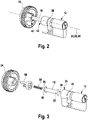
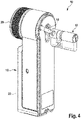
- the Figures 1 to 5 show the structure of a locking system 10 in different views.
- individual components of the locking system 10 are shown in detail.
- the locking system 10 can be mounted in a door.
- the locking system 10 can be used to actuate a lock of the door.
- the lock can be a mortise lock.
- the locking system 10 has a lock cylinder 12 and an actuating device 14 for actuating a lock cylinder 12 .
- the lock cylinder 12 can be inserted into the lock of the door.
- the actuating device 14 can be arranged, in particular attached or mounted, on an outer surface of the door.
- the actuating device 14 can be coupled to the lock cylinder 12 in order to actuate the latter.
- the actuation device 14 has an actuation device 16 and a cardan shaft 18 .
- the actuating device 16 can be coupled to the lock cylinder 12 by means of the articulated shaft 18 .
- the articulated shaft 18 is arranged between the actuating device 16 and the lock cylinder 12 .
- the cardan shaft 18 has a first end 36 which faces the actuating device 16 .
- the propshaft 18 has a second end 38 facing the key cylinder.
- the cardan shaft 18 can be rotated about a cardan shaft axis 32 .
- the articulated shaft axis 32 extends from the first end 36 to the second end 38.
- the articulated shaft 18 is essentially cylindrical with respect to the articulated shaft axis 32.
- the actuating device 16 has an actuating element 24 .
- the actuation element 24 can be rotated about an actuation axis 30 .
- the actuation axis 30 extends from a side of the actuating device 16 facing the articulated shaft 18 to a side of the actuating device 16 facing away from the articulated shaft 18 .
- the actuating element 24 is on the side of the actuating device facing the articulated shaft 18 16 arranged.
- the actuating element 24 is coupled to the first end 36 of the universal joint shaft 18 via a first joint 40 .
- the first joint 40 is designed as a pedestal joint.
- the first joint 40 is designed in such a way that a rotary motion of the actuating element 24 about the actuating axis 30 and a rotary motion of the articulated shaft 18 about the articulated shaft axis 32 are coupled to one another.
- the actuating device 16 also has a manual actuating element 20 .
- the actuating element 20 is designed to rotate the actuating element 24 about the actuating axis 30 when actuated manually.
- the actuating element 20 can be a rotary knob, for example, which is coupled to the actuating element 24 in such a way that a rotary movement of the rotary knob about its bearing axis can be transferred to a rotary movement of the actuating element 24 about the actuating axis 30 .
- the actuating device 16 also has a drive device 22 .
- the drive device 22 is designed to rotate the actuating element 24 about the actuating axis 30 .
- the drive device 22 can have an electric motor, for example, which is coupled to the actuating element 24 in such a way that it rotates the actuating element 24 about the actuating axis 30 .
- the actuating device can have an actuating device housing.
- the actuating element 24 and the drive device 22 can be arranged in the actuating device housing.
- the actuating element 24 can be mounted in the actuating device housing such that it can rotate about the actuating axis 30 .
- the actuating element 20 can be arranged on the actuating device housing and also be rotatably mounted.
- the lock cylinder 12 has a lock cylinder housing 25 .
- a rotating element 26 and a cam 28 are arranged in the lock cylinder housing 25 .
- the cam 28 is adapted to actuate a bolt and/or latch of the lock of the door when the lock cylinder 12 is mounted in the lock.
- the rotating element 26 and the cam 28 are rotatable in the lock cylinder housing 25 about a lock cylinder axis 34 rotatably mounted.
- the rotary element 26 is cylindrical with respect to the lock cylinder axis 34 .
- the lock cylinder axis 34 extends from a side of the lock cylinder 12 facing the articulated shaft 18 to a side of the lock cylinder 12 facing away from the articulated shaft 18 .
- the rotating element 26 can be coupled to the second end 38 of the universal joint shaft 18 via a second joint 42 .
- the second joint 42 is designed as a pedestal joint.
- the second joint 42 is designed in such a way that, in the coupled state, a rotary movement of the rotary element 26 about the lock cylinder axis 34 and a rotary movement of the articulated shaft 18 about the articulated shaft axis 32 are coupled to one another.
- the articulated shaft 18 is coupled to the actuating element 24 and the rotary element 26 via the first and second joint 40, 42.
- the actuation device 14 and the lock cylinder 12 are arranged in such a way that the actuation axis 30, the drive shaft axis 32 and the lock cylinder axis 34 are aligned with one another.
- the actuation axis 30, the articulated shaft axis 32 and the lock cylinder axis 34 are arranged concentrically.
- the actuation device 14 and the lock cylinder 12 are arranged in such a way that the actuation axis 30, the articulated shaft axis 32 and the lock cylinder axis 34 are not aligned with one another.
- the actuation axis 30, the cardan shaft axis 32 and the locking cylinder axis 34 are arranged eccentrically.
- the cardan shaft 18 has four first projections 48 on the first end 36 .
- the four first projections 48 are of identical design. In particular, the first projections 48 have the same shape and size.
- the first projections 48 extend outwards from the propeller shaft 18 radially to the propeller shaft axis 32 .
- the four first projections 48 are arranged in the circumferential direction around the cardan shaft axis 32 at equal distances of 90° from one another.
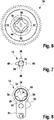
- the first end 36 is cross-shaped by means of the first projections 48 . For example, this is in 7 12, which is a plan view of the first end 36 of the propshaft 18.
- the cardan shaft 18 has four second projections 50 on the second end 38 .
- the four second projections 50 are of identical design.
- the second Projections 50 same shape and size.
- the second projections 50 extend outwards from the propeller shaft 18 radially to the propeller shaft axis 32 .
- the four second projections 50 are arranged in the circumferential direction around the cardan shaft axis 32 at equal distances of 90° from one another.
- the second end 38 is cross-shaped by means of the second projections 50 .
- the second projections 50 are identical to the first projections 48 .
- the second projections 50 have the same shape and size as the first projections 48.
- the outer diameter of the universal joint shaft 18 is constant between the first end 36 and the second end 38 of the universal joint shaft. Due to the first projections 48 at the first end 36 and the second projections 50 at the second end 38, the outer diameter of the cardan shaft is larger at the two ends 36, 38 than between the two ends. Since the first projections 36 and the second projections are of identical design, the outer diameter at the first end 36 corresponds to the outer diameter at the second end 38 of the cardan shaft 18.
- the actuating element 24 has a first receptacle 44 for the first end 36 of the articulated shaft 18 .
- the first receptacle 44 is arranged on a side of the actuating element 24 facing the articulated shaft 18 .
- a depth of the first receptacle 44 in an axial direction of the actuation axis 30 is greater than a length of the first projections 48 in an axial direction of the cardan shaft axis 32.
- the first receptacle 44 has four first recesses 52 .
- the four first recesses 52 are of identical design. In particular, the first recesses 52 have the same shape and size.
- the first recesses 52 extend radially to the actuation axis 30 from the receptacle 44 to the outside.
- the four first recesses 52 are arranged in the circumferential direction around the actuation axis 30 at equal distances of 90° from one another. In other words, the first receptacle 44 is cross-shaped by means of the first recesses 52 .
- the first recesses 52 are rectangular.
- the first projections 48 and the first recesses 52 are formed such that the first projections 48 can be engaged with the first recesses 52 to transmit torque.
- a width of the first recesses 52 in the circumferential direction around the actuation axis 30 is greater than or equal to a width of the first projections 48 in the circumferential direction around the cardan shaft axis 32.
- a radial extent of the first recesses 52 in a radial direction from the actuation axis 30 is greater than or equal to a height of the first projections 48 in a radial direction from the articulated shaft axis 32.
- a depth of the first recesses 52 in an axial direction along the actuation axis 30 is greater than a length of the first projections 48 in an axial direction along the articulated shaft axis 32.
- the first end 36 of the articulated shaft 18 is inserted into the first receptacle 44 .
- the first projections 48 are inserted into the first recesses 52 in the axial direction of the actuation axis 30 .
- the first projections 48 are arranged in the first recesses 52 .
- the first protrusions 48 are engageable with the first recesses 52 in the circumferential direction to transmit torque. In this way, a rotary motion of the actuating element 24 about the actuating axis 30 can be transferred to a rotary motion of the articulated shaft 18 about the articulated shaft axis 32 .
- the first joint 40 is formed by the first receptacle 44 and the first end 36 of the universal joint shaft 18 .
- the joint 40 is coupled via the first projections 48 and the first recesses 52.
- the actuating device 16 also has a spring element 56 .
- the spring element 56 is in 3 shown.
- the spring element 56 is arranged in the first receptacle 44 between the articulated shaft 18 and the actuating element 24 , in particular between a bottom of the first receptacle 44 and the first end 36 of the articulated shaft 18 .
- the spring element 56 is prestressed in a direction parallel to the actuation axis 30 .
- the spring element 56 is designed in particular in such a way that it pushes the first end 36 of the articulated shaft 18 away from the actuating element 24 .
- the articulated shaft 18 is thus pressed in the direction of the lock cylinder 12 by means of the spring element 56 .
- the actuating device 16 also has a holding element 58 .
- the holding element 58 is 3 shown and is in the views of figures 2 and 5 omitted so that the placement of the first end 36 in the first receptacle 44 can be seen in detail to illustrate the formation of the first hinge 40.
- the holding element 58 is arranged on a side of the actuating element 24 facing the articulated shaft 18 .
- the holding element 58 can be attached to the actuating element 24, for example by means of a plug and/or clip connection. In the assembled state, the holding element 58 is attached to the actuating element 24 .
- the holding element 58 has the function of a cover or a protective cap which is intended to prevent the first end 36 of the articulated shaft 18 from being able to escape from the first receptacle 44 in the assembled state.
- the holding element 58 holds the first end 36 of the articulated shaft 18 in the first receptacle 44.
- the holding element 58 is designed like a sleeve for this purpose and has an opening through which the articulated shaft 18 is guided. The opening is configured such that when assembled, an inside diameter of the opening is greater than or equal to an outside diameter of the propshaft 18 between the first and second ends 36 , 38 and is less than an outside diameter of the propshaft 18 at the first end 36 .
- the outside diameter of the propshaft 18 at the first end 36 is defined by the first projections 48 .
- the opening of the holding element 58 is designed in such a way that, in the assembled state, the first projections 48 cannot come out of the first recesses 52 and accordingly remain in engagement with them.
- the rotating element 26 has a second receptacle 46 for the second end 38 of the cardan shaft 18 .
- the second receptacle 46 is arranged on a side of the rotary element 26 facing the articulated shaft 18 . In 8 a top view of this page is shown.
- a depth of the second receptacle 46 in an axial direction of the lock cylinder axis 34 is greater than a length of the second projections 50 in an axial direction of the cardan shaft axis 32.
- the second receptacle 46 has four second recesses 54 .
- the four second recesses 54 are of identical design. In particular, the second recesses 54 have the same shape and size.
- the second recesses 54 extend radially to the lock cylinder axis 34 from the second receptacle 46 to the outside.
- the four second recesses 54 are arranged in the circumferential direction around the lock cylinder axis 34 at equal distances of 90° from one another.
- the second receptacle 46 is designed in the shape of a cross by means of the second recesses 54 .
- the second recesses 54 are rectangular.
- the second projections 50 and the second recesses 54 are formed such that the second projections 50 can be engaged with the second recesses 54 to transmit torque.
- a width of the second recesses 54 in the circumferential direction about the lock cylinder axis 34 is greater than or equal to a width of the second projections 50 in the circumferential direction about the joint shaft axis 32.
- a radial extent of the second recesses 54 in a radial direction from the lock cylinder axis 34 is greater than or equal to one Height of the second projections 50 in a radial direction from the articulated shaft axis 32.
- a depth of the second recesses 54 in an axial direction along the lock cylinder axis 34 is greater than a length of the second projections 50 in an axial direction along the articulated shaft axis 32.
- the second end 38 of the propshaft 18 is inserted into the second receptacle 46 .
- the second projections 50 are inserted into the second recesses 54 in the axial direction of the lock cylinder axis 34 .
- the second projections 50 are arranged in the second recesses 54 .
- the second protrusions 50 are engageable with the second recesses 54 in the circumferential direction to transmit torque. In this way, a rotational movement of the cardan shaft 18 about the cardan shaft axis 32 can be transferred to a rotary movement of the rotary element 26 about the lock cylinder axis 34 .
- the second joint 42 is formed by the second mount 46 and the second end 38 of the universal joint shaft 18 .
- the joint 42 is coupled via the second projections 50 and the second recesses 54.
- first and second projections 48,50 are collectively referred to as projections 48,50.
- Each projection 48, 50 has an outer surface 60 and two side surfaces 62.
- FIG. The outer surface 60 and the side surfaces 62 are surfaces of the projection 48, 50.
- the outer surface 60 is arranged radially on the outside with respect to the cardan shaft axis 32 on the respective projection 48, 50.
- the side surfaces 62 are arranged in the circumferential direction about the propeller shaft axis 32 on opposite sides of the respective projection 48, 50.
- the outer surface 60 is thus arranged between the side surfaces 62 .
- the outer surface 60 connects the two side surfaces 62.
- each projection 48, 50 corresponds to the greatest distance between the two side surfaces 62 in the circumferential direction around the articulated shaft axis 32.
- the height of each projection 48, 50 corresponds to the greatest radial distance from the articulated shaft axis to the outer surface 60.
- the length of each projection 48, 50 corresponds the axial extension of the respective projection 48, 50 parallel to the cardan shaft axis.
- the outer surface 60 is convex.
- the radius of curvature of the outer surface 60 is one-half the diameter of the propshaft 18 at the first and second ends 36, 38 of the propshaft 18.
- the diameter of the propshaft 18 at the first and second ends 36, 38 is the sum of the diameters of the propshaft 18 between the ends 36, 38 and twice the radial extent of each projection 48, 50.
- the reference point of the radius of curvature is thus on the propeller shaft axis 32.
- the height of each projection 48, 50 may be less than or equal to the radial extent of each recess 52, 54.
- the two side surfaces 62 are preferably designed to be mirror-symmetrical to one another.
- the two side surfaces 62 are convex.
- the radii of curvature of the two side surfaces 62 are of the same size.
- the radii of curvature of the two side surfaces 62 are each greater than half the width of each projection 48,50, with the width of each projection 48,50 being smaller than the width of each recess 52,54.
- the radii of curvature of the two side surfaces 62 can also be equal to half the width of each projection 48, 50, with the width of each projection 48, 50 being less than or equal to the width of each recess 52, 54.
- the projections can be designed in particular as pins, with the two side surfaces 62 each having the shape of a semi-cylinder.
- the locking system can be the locking system 10 that in the Figures 1 to 11 is described.
- the lock cylinder 12 is inserted into a recess in the door provided for this purpose.
- the lock cylinder 12 is inserted and fixed in a lock of the door, the lock having the recess of the door.
- step 104 of the method 100 the second end 38 of the universal joint shaft 18 is coupled to the rotating element 26 .
- the second end 38 of the articulated shaft 18 is inserted into the second receptacle 46 .
- the second projections 50 are inserted into and engaged with the second recesses 54 .
- the actuating device 16 is positioned on an outer surface of the door.
- the actuating device 16 can be placed on the outer surface of the door above or next to the recess in the door and can be offset along the outer surface, in particular until attachment points of the actuating device 16 are aligned with corresponding attachment points on the door.
- the actuating device is attached to the door.
- the actuating device can be attached to the door by means of one or more attachment means such as screws.
- the fastening means can connect the attachment points of the actuating device 16 to the corresponding attachment points of the door.
Landscapes
- Engineering & Computer Science (AREA)
- Mechanical Engineering (AREA)
- Physics & Mathematics (AREA)
- Electromagnetism (AREA)
- Lock And Its Accessories (AREA)
Applications Claiming Priority (1)
| Application Number | Priority Date | Filing Date | Title |
|---|---|---|---|
| DE102021101986.9A DE102021101986B4 (de) | 2021-01-28 | 2021-01-28 | Aktuierungsvorrichtung, Schließzylinder, Schließsystem und Verfahren |
Publications (3)
| Publication Number | Publication Date |
|---|---|
| EP4036355A1 true EP4036355A1 (fr) | 2022-08-03 |
| EP4036355C0 EP4036355C0 (fr) | 2025-09-17 |
| EP4036355B1 EP4036355B1 (fr) | 2025-09-17 |
Family
ID=80034762
Family Applications (1)
| Application Number | Title | Priority Date | Filing Date |
|---|---|---|---|
| EP22153527.1A Active EP4036355B1 (fr) | 2021-01-28 | 2022-01-26 | Dispositif actionneur, cylindre de fermeture, système et procédé de verrouillage |
Country Status (3)
| Country | Link |
|---|---|
| EP (1) | EP4036355B1 (fr) |
| DE (1) | DE102021101986B4 (fr) |
| ES (1) | ES3057134T3 (fr) |
Cited By (1)
| Publication number | Priority date | Publication date | Assignee | Title |
|---|---|---|---|---|
| CN119641174A (zh) * | 2024-10-31 | 2025-03-18 | 杭州华橙软件技术有限公司 | 智能锁 |
Citations (5)
| Publication number | Priority date | Publication date | Assignee | Title |
|---|---|---|---|---|
| EP0722028A1 (fr) * | 1995-01-14 | 1996-07-17 | Rockwell Light Vehicle Systems (Uk) Limited | Serrure de porte pour véhicules |
| JP2010190030A (ja) * | 2009-01-20 | 2010-09-02 | Alpha Corp | シリンダ錠 |
| DE102011052811A1 (de) * | 2011-08-18 | 2013-02-21 | Dom-Sicherheitstechnik Gmbh & Co. Kg | Knauf-Zylinder mit druckknopfbetätigbarer Kupplung |
| WO2014182509A1 (fr) | 2013-05-06 | 2014-11-13 | Mul-T-Lock Technologies Ltd. | Serrure à barillet électromécanique à clé d'ouverture manuelle |
| CN206545433U (zh) | 2016-08-22 | 2017-10-10 | 浙江钜士安防科技股份有限公司 | 一种电子锁万能反锁器 |
Family Cites Families (3)
| Publication number | Priority date | Publication date | Assignee | Title |
|---|---|---|---|---|
| FR2776329B1 (fr) | 1998-03-17 | 2000-04-28 | Valeo Securite Habitacle | Agencement pour la transmission de mouvement entre un verrou et une serrure de vehicule automobile |
| DE102005020804A1 (de) | 2005-05-04 | 2006-11-09 | Hewi Heinrich Wilke Gmbh | Schließzylinder für ein elektronisches Schließsystem |
| FR2916787B1 (fr) | 2007-06-04 | 2011-04-08 | Renault Sas | Dispositif de liaison entre un verrou et une serrure de porte de vehicule automobile |
-
2021
- 2021-01-28 DE DE102021101986.9A patent/DE102021101986B4/de active Active
-
2022
- 2022-01-26 ES ES22153527T patent/ES3057134T3/es active Active
- 2022-01-26 EP EP22153527.1A patent/EP4036355B1/fr active Active
Patent Citations (5)
| Publication number | Priority date | Publication date | Assignee | Title |
|---|---|---|---|---|
| EP0722028A1 (fr) * | 1995-01-14 | 1996-07-17 | Rockwell Light Vehicle Systems (Uk) Limited | Serrure de porte pour véhicules |
| JP2010190030A (ja) * | 2009-01-20 | 2010-09-02 | Alpha Corp | シリンダ錠 |
| DE102011052811A1 (de) * | 2011-08-18 | 2013-02-21 | Dom-Sicherheitstechnik Gmbh & Co. Kg | Knauf-Zylinder mit druckknopfbetätigbarer Kupplung |
| WO2014182509A1 (fr) | 2013-05-06 | 2014-11-13 | Mul-T-Lock Technologies Ltd. | Serrure à barillet électromécanique à clé d'ouverture manuelle |
| CN206545433U (zh) | 2016-08-22 | 2017-10-10 | 浙江钜士安防科技股份有限公司 | 一种电子锁万能反锁器 |
Cited By (2)
| Publication number | Priority date | Publication date | Assignee | Title |
|---|---|---|---|---|
| CN119641174A (zh) * | 2024-10-31 | 2025-03-18 | 杭州华橙软件技术有限公司 | 智能锁 |
| CN119641174B (zh) * | 2024-10-31 | 2026-02-24 | 杭州华橙软件技术有限公司 | 智能锁 |
Also Published As
| Publication number | Publication date |
|---|---|
| DE102021101986A1 (de) | 2022-07-28 |
| EP4036355C0 (fr) | 2025-09-17 |
| DE102021101986B4 (de) | 2022-09-15 |
| EP4036355B1 (fr) | 2025-09-17 |
| ES3057134T3 (en) | 2026-02-26 |
Similar Documents
| Publication | Publication Date | Title |
|---|---|---|
| EP0164792B1 (fr) | Dispositif pour l'accouplement positif de deux arbres | |
| DE102019003546A1 (de) | Adapter für einen Antrieb und Antrieb | |
| DE102011014621B4 (de) | Verbindungsanordnung einer Welle-Nabe-Verbindung | |
| EP1664564B1 (fr) | Systeme pour relier un arbre a une articulation | |
| DE102021101986B4 (de) | Aktuierungsvorrichtung, Schließzylinder, Schließsystem und Verfahren | |
| DE8215152U1 (de) | Kugeluniversalgelenk | |
| EP3626914B1 (fr) | Ferrure avec poignée et dispositif de rappel pour la poignée et procédé de transfert d'un dispositif de rappel entre une première position d'arrêt et une seconde position d'arrêt de la poignée | |
| WO2013174618A1 (fr) | Amortisseur de vibrations, en particulier amortisseur de tige de piston pour un véhicule automobile | |
| DE19950597A1 (de) | Antriebsanordnung | |
| EP3659217B1 (fr) | Dispositif de contact | |
| EP0570394B1 (fr) | Dispositif de stabilisation et de soutien du palier pivotant de levier d'embrayage | |
| EP0342260B1 (fr) | Accouplement flexible pour opération intermittente par exemple entraînement de commutateurs | |
| DE102023202267A1 (de) | Schwingungsdämpfer mit einer Montagekappe | |
| DE102010055192A1 (de) | Verbrennungsmotor mit Führung zum Abstecken der Nockenwelle sowie Verschlusselement | |
| EP1161632B1 (fr) | Accouplement de deux extremites d'arbres mobiles en rotation | |
| DE3448221C2 (en) | Steering and ignition lock for motor vehicles | |
| DE102024124827B4 (de) | Muffenvorrichtung insbesondere für eine Entkoppelungseinrichtung in einem elektrischen Antriebsstrang und Verfahren zu deren Montage und Demontage | |
| EP4506582B1 (fr) | Arbre de fourche | |
| DE202005020263U1 (de) | Mehrfachkupplung für Medienleitungen | |
| DE19813546B4 (de) | Drehmomentübertragende Verbindung einer ersten mit einer zweiten Welle | |
| EP4031785B1 (fr) | Ensemble garniture d'étanchéité mécanique pouvant être montée axialement | |
| EP0826854A2 (fr) | Dispositif d'accouplement pour une serrure cylindrique | |
| EP1577465A1 (fr) | Élément de verrouillage avec fixation pour élément d'actionnement | |
| EP4624297A1 (fr) | Attelage de traction | |
| DE102024104572A1 (de) | Leitungseinführstutzen |
Legal Events
| Date | Code | Title | Description |
|---|---|---|---|
| PUAI | Public reference made under article 153(3) epc to a published international application that has entered the european phase |
Free format text: ORIGINAL CODE: 0009012 |
|
| STAA | Information on the status of an ep patent application or granted ep patent |
Free format text: STATUS: THE APPLICATION HAS BEEN PUBLISHED |
|
| AK | Designated contracting states |
Kind code of ref document: A1 Designated state(s): AL AT BE BG CH CY CZ DE DK EE ES FI FR GB GR HR HU IE IS IT LI LT LU LV MC MK MT NL NO PL PT RO RS SE SI SK SM TR |
|
| STAA | Information on the status of an ep patent application or granted ep patent |
Free format text: STATUS: REQUEST FOR EXAMINATION WAS MADE |
|
| 17P | Request for examination filed |
Effective date: 20230131 |
|
| RAP3 | Party data changed (applicant data changed or rights of an application transferred) |
Owner name: DOM SICHERHEITSTECHNIK GMBH & CO. KG |
|
| RBV | Designated contracting states (corrected) |
Designated state(s): AL AT BE BG CH CY CZ DE DK EE ES FI FR GB GR HR HU IE IS IT LI LT LU LV MC MK MT NL NO PL PT RO RS SE SI SK SM TR |
|
| GRAP | Despatch of communication of intention to grant a patent |
Free format text: ORIGINAL CODE: EPIDOSNIGR1 |
|
| STAA | Information on the status of an ep patent application or granted ep patent |
Free format text: STATUS: GRANT OF PATENT IS INTENDED |
|
| INTG | Intention to grant announced |
Effective date: 20250417 |
|
| GRAS | Grant fee paid |
Free format text: ORIGINAL CODE: EPIDOSNIGR3 |
|
| GRAA | (expected) grant |
Free format text: ORIGINAL CODE: 0009210 |
|
| STAA | Information on the status of an ep patent application or granted ep patent |
Free format text: STATUS: THE PATENT HAS BEEN GRANTED |
|
| AK | Designated contracting states |
Kind code of ref document: B1 Designated state(s): AL AT BE BG CH CY CZ DE DK EE ES FI FR GB GR HR HU IE IS IT LI LT LU LV MC MK MT NL NO PL PT RO RS SE SI SK SM TR |
|
| REG | Reference to a national code |
Ref country code: GB Ref legal event code: FG4D Free format text: NOT ENGLISH |
|
| REG | Reference to a national code |
Ref country code: CH Ref legal event code: EP |
|
| REG | Reference to a national code |
Ref country code: IE Ref legal event code: FG4D Free format text: LANGUAGE OF EP DOCUMENT: GERMAN |
|
| REG | Reference to a national code |
Ref country code: DE Ref legal event code: R096 Ref document number: 502022005486 Country of ref document: DE |
|
| U01 | Request for unitary effect filed |
Effective date: 20251015 |
|
| U07 | Unitary effect registered |
Designated state(s): AT BE BG DE DK EE FI FR IT LT LU LV MT NL PT RO SE SI Effective date: 20251021 |
|
| PG25 | Lapsed in a contracting state [announced via postgrant information from national office to epo] |
Ref country code: NO Free format text: LAPSE BECAUSE OF FAILURE TO SUBMIT A TRANSLATION OF THE DESCRIPTION OR TO PAY THE FEE WITHIN THE PRESCRIBED TIME-LIMIT Effective date: 20251217 |
|
| PG25 | Lapsed in a contracting state [announced via postgrant information from national office to epo] |
Ref country code: HR Free format text: LAPSE BECAUSE OF FAILURE TO SUBMIT A TRANSLATION OF THE DESCRIPTION OR TO PAY THE FEE WITHIN THE PRESCRIBED TIME-LIMIT Effective date: 20250917 |
|
| PG25 | Lapsed in a contracting state [announced via postgrant information from national office to epo] |
Ref country code: GR Free format text: LAPSE BECAUSE OF FAILURE TO SUBMIT A TRANSLATION OF THE DESCRIPTION OR TO PAY THE FEE WITHIN THE PRESCRIBED TIME-LIMIT Effective date: 20251218 |
|
| PG25 | Lapsed in a contracting state [announced via postgrant information from national office to epo] |
Ref country code: RS Free format text: LAPSE BECAUSE OF FAILURE TO SUBMIT A TRANSLATION OF THE DESCRIPTION OR TO PAY THE FEE WITHIN THE PRESCRIBED TIME-LIMIT Effective date: 20251217 |
|
| REG | Reference to a national code |
Ref country code: ES Ref legal event code: FG2A Ref document number: 3057134 Country of ref document: ES Kind code of ref document: T3 Effective date: 20260226 |
|
| U20 | Renewal fee for the european patent with unitary effect paid |
Year of fee payment: 5 Effective date: 20260131 |
|
| PG25 | Lapsed in a contracting state [announced via postgrant information from national office to epo] |
Ref country code: SM Free format text: LAPSE BECAUSE OF FAILURE TO SUBMIT A TRANSLATION OF THE DESCRIPTION OR TO PAY THE FEE WITHIN THE PRESCRIBED TIME-LIMIT Effective date: 20250917 |
|
| PGFP | Annual fee paid to national office [announced via postgrant information from national office to epo] |
Ref country code: GB Payment date: 20260121 Year of fee payment: 5 |
|
| PGFP | Annual fee paid to national office [announced via postgrant information from national office to epo] |
Ref country code: ES Payment date: 20260217 Year of fee payment: 5 |
|
| PG25 | Lapsed in a contracting state [announced via postgrant information from national office to epo] |
Ref country code: IS Free format text: LAPSE BECAUSE OF FAILURE TO SUBMIT A TRANSLATION OF THE DESCRIPTION OR TO PAY THE FEE WITHIN THE PRESCRIBED TIME-LIMIT Effective date: 20260117 |
|
| PG25 | Lapsed in a contracting state [announced via postgrant information from national office to epo] |
Ref country code: CZ Free format text: LAPSE BECAUSE OF FAILURE TO SUBMIT A TRANSLATION OF THE DESCRIPTION OR TO PAY THE FEE WITHIN THE PRESCRIBED TIME-LIMIT Effective date: 20250917 |
|
| PG25 | Lapsed in a contracting state [announced via postgrant information from national office to epo] |
Ref country code: PL Free format text: LAPSE BECAUSE OF FAILURE TO SUBMIT A TRANSLATION OF THE DESCRIPTION OR TO PAY THE FEE WITHIN THE PRESCRIBED TIME-LIMIT Effective date: 20250917 |
|
| PG25 | Lapsed in a contracting state [announced via postgrant information from national office to epo] |
Ref country code: SK Free format text: LAPSE BECAUSE OF FAILURE TO SUBMIT A TRANSLATION OF THE DESCRIPTION OR TO PAY THE FEE WITHIN THE PRESCRIBED TIME-LIMIT Effective date: 20250917 |