EP3659232B1 - Station de charge à distribution dynamique de courant de charge - Google Patents
Station de charge à distribution dynamique de courant de charge Download PDFInfo
- Publication number
- EP3659232B1 EP3659232B1 EP18746679.2A EP18746679A EP3659232B1 EP 3659232 B1 EP3659232 B1 EP 3659232B1 EP 18746679 A EP18746679 A EP 18746679A EP 3659232 B1 EP3659232 B1 EP 3659232B1
- Authority
- EP
- European Patent Office
- Prior art keywords
- charging
- terminal
- chopper
- current
- terminals
- Prior art date
- Legal status (The legal status is an assumption and is not a legal conclusion. Google has not performed a legal analysis and makes no representation as to the accuracy of the status listed.)
- Active
Links
Images

Classifications
-
- B—PERFORMING OPERATIONS; TRANSPORTING
- B60—VEHICLES IN GENERAL
- B60L—PROPULSION OF ELECTRICALLY-PROPELLED VEHICLES; SUPPLYING ELECTRIC POWER FOR AUXILIARY EQUIPMENT OF ELECTRICALLY-PROPELLED VEHICLES; ELECTRODYNAMIC BRAKE SYSTEMS FOR VEHICLES IN GENERAL; MAGNETIC SUSPENSION OR LEVITATION FOR VEHICLES; MONITORING OPERATING VARIABLES OF ELECTRICALLY-PROPELLED VEHICLES; ELECTRIC SAFETY DEVICES FOR ELECTRICALLY-PROPELLED VEHICLES
- B60L53/00—Methods of charging batteries, specially adapted for electric vehicles; Charging stations or on-board charging equipment therefor; Exchange of energy storage elements in electric vehicles
- B60L53/30—Constructional details of charging stations
- B60L53/31—Charging columns specially adapted for electric vehicles
-
- H—ELECTRICITY
- H02—GENERATION; CONVERSION OR DISTRIBUTION OF ELECTRIC POWER
- H02J—ELECTRIC POWER NETWORKS; CIRCUIT ARRANGEMENTS OR SYSTEMS FOR SUPPLYING OR DISTRIBUTING ELECTRIC POWER; SYSTEMS FOR STORING ELECTRIC ENERGY
- H02J1/00—Circuit arrangements for DC mains or DC distribution networks
- H02J1/10—Parallel operation of DC sources
- H02J1/102—Parallel operation of DC sources being switching converters
-
- B—PERFORMING OPERATIONS; TRANSPORTING
- B60—VEHICLES IN GENERAL
- B60L—PROPULSION OF ELECTRICALLY-PROPELLED VEHICLES; SUPPLYING ELECTRIC POWER FOR AUXILIARY EQUIPMENT OF ELECTRICALLY-PROPELLED VEHICLES; ELECTRODYNAMIC BRAKE SYSTEMS FOR VEHICLES IN GENERAL; MAGNETIC SUSPENSION OR LEVITATION FOR VEHICLES; MONITORING OPERATING VARIABLES OF ELECTRICALLY-PROPELLED VEHICLES; ELECTRIC SAFETY DEVICES FOR ELECTRICALLY-PROPELLED VEHICLES
- B60L53/00—Methods of charging batteries, specially adapted for electric vehicles; Charging stations or on-board charging equipment therefor; Exchange of energy storage elements in electric vehicles
- B60L53/10—Methods of charging batteries, specially adapted for electric vehicles; Charging stations or on-board charging equipment therefor; Exchange of energy storage elements in electric vehicles characterised by the energy transfer between the charging station and the vehicle
- B60L53/14—Conductive energy transfer
-
- B—PERFORMING OPERATIONS; TRANSPORTING
- B60—VEHICLES IN GENERAL
- B60L—PROPULSION OF ELECTRICALLY-PROPELLED VEHICLES; SUPPLYING ELECTRIC POWER FOR AUXILIARY EQUIPMENT OF ELECTRICALLY-PROPELLED VEHICLES; ELECTRODYNAMIC BRAKE SYSTEMS FOR VEHICLES IN GENERAL; MAGNETIC SUSPENSION OR LEVITATION FOR VEHICLES; MONITORING OPERATING VARIABLES OF ELECTRICALLY-PROPELLED VEHICLES; ELECTRIC SAFETY DEVICES FOR ELECTRICALLY-PROPELLED VEHICLES
- B60L53/00—Methods of charging batteries, specially adapted for electric vehicles; Charging stations or on-board charging equipment therefor; Exchange of energy storage elements in electric vehicles
- B60L53/60—Monitoring or controlling charging stations
- B60L53/62—Monitoring or controlling charging stations in response to charging parameters, e.g. current, voltage or electrical charge
-
- B—PERFORMING OPERATIONS; TRANSPORTING
- B60—VEHICLES IN GENERAL
- B60L—PROPULSION OF ELECTRICALLY-PROPELLED VEHICLES; SUPPLYING ELECTRIC POWER FOR AUXILIARY EQUIPMENT OF ELECTRICALLY-PROPELLED VEHICLES; ELECTRODYNAMIC BRAKE SYSTEMS FOR VEHICLES IN GENERAL; MAGNETIC SUSPENSION OR LEVITATION FOR VEHICLES; MONITORING OPERATING VARIABLES OF ELECTRICALLY-PROPELLED VEHICLES; ELECTRIC SAFETY DEVICES FOR ELECTRICALLY-PROPELLED VEHICLES
- B60L53/00—Methods of charging batteries, specially adapted for electric vehicles; Charging stations or on-board charging equipment therefor; Exchange of energy storage elements in electric vehicles
- B60L53/60—Monitoring or controlling charging stations
- B60L53/67—Controlling two or more charging stations
-
- B—PERFORMING OPERATIONS; TRANSPORTING
- B60—VEHICLES IN GENERAL
- B60L—PROPULSION OF ELECTRICALLY-PROPELLED VEHICLES; SUPPLYING ELECTRIC POWER FOR AUXILIARY EQUIPMENT OF ELECTRICALLY-PROPELLED VEHICLES; ELECTRODYNAMIC BRAKE SYSTEMS FOR VEHICLES IN GENERAL; MAGNETIC SUSPENSION OR LEVITATION FOR VEHICLES; MONITORING OPERATING VARIABLES OF ELECTRICALLY-PROPELLED VEHICLES; ELECTRIC SAFETY DEVICES FOR ELECTRICALLY-PROPELLED VEHICLES
- B60L55/00—Arrangements for supplying energy stored within a vehicle to a power network, i.e. vehicle-to-grid [V2G] arrangements
-
- H—ELECTRICITY
- H02—GENERATION; CONVERSION OR DISTRIBUTION OF ELECTRIC POWER
- H02J—ELECTRIC POWER NETWORKS; CIRCUIT ARRANGEMENTS OR SYSTEMS FOR SUPPLYING OR DISTRIBUTING ELECTRIC POWER; SYSTEMS FOR STORING ELECTRIC ENERGY
- H02J7/00—Circuit arrangements for charging or discharging batteries or for supplying loads from batteries
- H02J7/02—Circuit arrangements for charging or discharging batteries or for supplying loads from batteries for charging batteries from AC mains by converters
-
- H—ELECTRICITY
- H02—GENERATION; CONVERSION OR DISTRIBUTION OF ELECTRIC POWER
- H02J—ELECTRIC POWER NETWORKS; CIRCUIT ARRANGEMENTS OR SYSTEMS FOR SUPPLYING OR DISTRIBUTING ELECTRIC POWER; SYSTEMS FOR STORING ELECTRIC ENERGY
- H02J7/00—Circuit arrangements for charging or discharging batteries or for supplying loads from batteries
- H02J7/50—Circuit arrangements for charging or discharging batteries or for supplying loads from batteries acting upon multiple batteries simultaneously or sequentially
-
- B—PERFORMING OPERATIONS; TRANSPORTING
- B60—VEHICLES IN GENERAL
- B60L—PROPULSION OF ELECTRICALLY-PROPELLED VEHICLES; SUPPLYING ELECTRIC POWER FOR AUXILIARY EQUIPMENT OF ELECTRICALLY-PROPELLED VEHICLES; ELECTRODYNAMIC BRAKE SYSTEMS FOR VEHICLES IN GENERAL; MAGNETIC SUSPENSION OR LEVITATION FOR VEHICLES; MONITORING OPERATING VARIABLES OF ELECTRICALLY-PROPELLED VEHICLES; ELECTRIC SAFETY DEVICES FOR ELECTRICALLY-PROPELLED VEHICLES
- B60L2210/00—Converter types
- B60L2210/10—DC to DC converters
-
- B—PERFORMING OPERATIONS; TRANSPORTING
- B60—VEHICLES IN GENERAL
- B60Y—INDEXING SCHEME RELATING TO ASPECTS CROSS-CUTTING VEHICLE TECHNOLOGY
- B60Y2200/00—Type of vehicle
- B60Y2200/90—Vehicles comprising electric prime movers
- B60Y2200/91—Electric vehicles
-
- H—ELECTRICITY
- H02—GENERATION; CONVERSION OR DISTRIBUTION OF ELECTRIC POWER
- H02J—ELECTRIC POWER NETWORKS; CIRCUIT ARRANGEMENTS OR SYSTEMS FOR SUPPLYING OR DISTRIBUTING ELECTRIC POWER; SYSTEMS FOR STORING ELECTRIC ENERGY
- H02J2207/00—Details of circuit arrangements for charging or discharging batteries or supplying loads from batteries
- H02J2207/20—Charging or discharging characterised by the power electronics converter
-
- H—ELECTRICITY
- H02—GENERATION; CONVERSION OR DISTRIBUTION OF ELECTRIC POWER
- H02M—APPARATUS FOR CONVERSION BETWEEN AC AND AC, BETWEEN AC AND DC, OR BETWEEN DC AND DC, AND FOR USE WITH MAINS OR SIMILAR POWER SUPPLY SYSTEMS; CONVERSION OF DC OR AC INPUT POWER INTO SURGE OUTPUT POWER; CONTROL OR REGULATION THEREOF
- H02M3/00—Conversion of DC power input into DC power output
- H02M3/22—Conversion of DC power input into DC power output with intermediate conversion into AC
- H02M3/34—Conversion of DC power input into DC power output with intermediate conversion into AC by dynamic converters
- H02M3/38—Conversion of DC power input into DC power output with intermediate conversion into AC by dynamic converters using mechanical contact-making and -breaking parts to interrupt a single potential
- H02M3/42—Conversion of DC power input into DC power output with intermediate conversion into AC by dynamic converters using mechanical contact-making and -breaking parts to interrupt a single potential with electromagnetically-operated vibrating contacts, e.g. chopper
-
- Y—GENERAL TAGGING OF NEW TECHNOLOGICAL DEVELOPMENTS; GENERAL TAGGING OF CROSS-SECTIONAL TECHNOLOGIES SPANNING OVER SEVERAL SECTIONS OF THE IPC; TECHNICAL SUBJECTS COVERED BY FORMER USPC CROSS-REFERENCE ART COLLECTIONS [XRACs] AND DIGESTS
- Y02—TECHNOLOGIES OR APPLICATIONS FOR MITIGATION OR ADAPTATION AGAINST CLIMATE CHANGE
- Y02T—CLIMATE CHANGE MITIGATION TECHNOLOGIES RELATED TO TRANSPORTATION
- Y02T10/00—Road transport of goods or passengers
- Y02T10/60—Other road transportation technologies with climate change mitigation effect
- Y02T10/70—Energy storage systems for electromobility, e.g. batteries
-
- Y—GENERAL TAGGING OF NEW TECHNOLOGICAL DEVELOPMENTS; GENERAL TAGGING OF CROSS-SECTIONAL TECHNOLOGIES SPANNING OVER SEVERAL SECTIONS OF THE IPC; TECHNICAL SUBJECTS COVERED BY FORMER USPC CROSS-REFERENCE ART COLLECTIONS [XRACs] AND DIGESTS
- Y02—TECHNOLOGIES OR APPLICATIONS FOR MITIGATION OR ADAPTATION AGAINST CLIMATE CHANGE
- Y02T—CLIMATE CHANGE MITIGATION TECHNOLOGIES RELATED TO TRANSPORTATION
- Y02T10/00—Road transport of goods or passengers
- Y02T10/60—Other road transportation technologies with climate change mitigation effect
- Y02T10/7072—Electromobility specific charging systems or methods for batteries, ultracapacitors, supercapacitors or double-layer capacitors
-
- Y—GENERAL TAGGING OF NEW TECHNOLOGICAL DEVELOPMENTS; GENERAL TAGGING OF CROSS-SECTIONAL TECHNOLOGIES SPANNING OVER SEVERAL SECTIONS OF THE IPC; TECHNICAL SUBJECTS COVERED BY FORMER USPC CROSS-REFERENCE ART COLLECTIONS [XRACs] AND DIGESTS
- Y02—TECHNOLOGIES OR APPLICATIONS FOR MITIGATION OR ADAPTATION AGAINST CLIMATE CHANGE
- Y02T—CLIMATE CHANGE MITIGATION TECHNOLOGIES RELATED TO TRANSPORTATION
- Y02T90/00—Enabling technologies or technologies with a potential or indirect contribution to GHG emissions mitigation
- Y02T90/10—Technologies relating to charging of electric vehicles
- Y02T90/12—Electric charging stations
Definitions
- the present invention relates to a charging station for charging several electric vehicles, in particular electric automobiles.
- the present invention also relates to a method for charging multiple electric vehicles.
- a charging infrastructure is to be able to charge electric vehicles in the shortest possible time.
- a particularly high demand for fast charging systems can be expected, particularly in areas with a high volume of electric vehicles. Examples of such areas are motorway service areas or inner city areas in a large city where long idle times for electric vehicles are not desired.
- a charging station When setting up or designing a charging station, technological challenges arise that must be addressed.
- One problem when operating a charging station for charging electric vehicles is, for example, that different vehicle types that are connected to the charging stations or charging terminals of the charging station have very different requirements for the charging current and charging voltages.
- a very high charging current may be required for quick charging, but this quickly drops again.
- a relatively constant current is required over a longer period of time. Since the charging terminals are usually designed to be able to charge all types of vehicles, a charging station would on average only be relatively underutilized. The charging terminal would then not always deliver its maximum charging current to an electric vehicle because the electric vehicle does not request it or only requests it intermittently.
- German Patent and Trademark Office has researched the following prior art in the priority application for this application: US 2010/0106631 A1 , US 2013/0057209 A1 , US 2014/0320083 A1 , JP H05-276673 A , WO 2013/137501 A1 .
- the document WO 2013/137501 A1 relates to a charging station with a single-sided noise filter, a power factor correction section and a plurality of DC/DC converters connected to the power factor correction section.
- the DC/DC inverters include a large charging port, a medium charging port and a normal charging port.
- the document KR 2011-0137675 A concerns a similar charging station to the document mentioned WO 2013/137501 A1 .
- the US disclosure document US 2013/0069592 A1 relates to a charging system for electric vehicles with multiple charging ports, each of which has an interface for exchanging power with at least one electric vehicle, as well as multiple power converters and a switchable connection matrix for connecting at least one power converter to at least one charging port.
- a controller is provided for controlling and a communication means for exchanging parameters with the at least one electric vehicle.
- the document JP 2013 027236 A relates to a battery charging system with a plurality of chargers, and a control device for controlling the plurality of chargers, the control unit changing the number of chargers for power supply according to the required power, which is determined from the remaining capacity of the battery and the rated output power of the charger.
- the object of the present invention is therefore to address at least one of the problems mentioned above.
- a solution should be proposed that at least enables better utilization of the charging terminals in the charging station.
- At least an alternative solution to previously known solutions should be proposed.
- a charging station according to claim 1 is therefore proposed. This is intended for charging multiple electric vehicles, especially electric automobiles. According to the invention, a method according to claim 12 is also proposed. Embodiments are further defined in the subclaims.
- the charging station thus comprises a supply device, in particular for connecting to an electrical supply network, in order to supply the charging station with electrical power.
- the charging station thus draws electrical power or electrical energy from the electrical supply network and makes it available to the charging terminals.
- the supply device can be connected to an electrical supply network, in particular via a transformer.
- a rectifier can be provided in the supply device in order to rectify alternating current drawn from the electrical supply network and to provide it to the charging terminals.
- the supply facility can also have an energy storage, in particular a battery, to buffer electrical energy.
- the charging station also includes several charging terminals.
- the charging terminals which can also be designed as charging stations, are fixed terminals to which - similar to petrol pumps at a conventional petrol station - the electric vehicles can be connected for charging via a charging cable. It is preferably provided that several electric vehicles can be connected to a charging terminal. The connection can also take place at the same time. According to one embodiment, two electric vehicles can be connected to the same charging terminal for charging at the same time.
- Each charging terminal includes a supply input, which can also be referred to synonymously as a supply input area, for obtaining electrical power from the supply device. This can be done directly or indirectly. Each charging terminal is therefore electrically coupled to the supply device and draws power provided by the supply device at the supply input.
- each charging terminal also includes a charging output, which can also be referred to synonymously as a charging output area, with one or more charging ports for each outputting a charging current for charging a connected electric vehicle. It is therefore proposed that each charging terminal has at least one charging port, with one electric vehicle being able to be connected to each charging port. The number of charging ports therefore corresponds to the number of electric vehicles that can be connected to the terminal.
- the charging connection is a connection point on the charging terminal to which, for example, a charging cable is connected in order to connect an electric vehicle to the terminal. Such a charging cable can also be viewed as part of the connection point.
- At least one DC current controller is proposed, which is arranged between the supply input and the charging output of the charging terminal in order to generate a current controller current from the electrical power of the supply device and also to control it.
- the direct current controller can also be simply and synonymously referred to as a current controller.
- two current controller currents can be generated independently of one another by a DC controller.
- the direct current controller converts the first direct voltage or the first direct current obtained via the supply input and provided by the supply device into a second direct current adapted for the electric vehicles.
- a typical power range of the DC converter which can also be referred to as a DC-DC converter, is 50 kW, whereby the converter can generate a current controller current of, for example, 125 A at 400 V DC or 62.5 A at 800 V DC. These are typical values for a charging current that can be used to charge electric vehicles.
- At least one DC controller in particular all DC controllers, can be changed internally, in particular switchable, so that they each change their voltage level depending on the requirements of the vehicle to be charged.
- they can each double or halve their voltage while simultaneously halving or doubling their output current.
- a charging terminal has at least one current controller terminal arranged between the supply input and the charging output in order to control a current controller current generated outside the charging terminal by a DC controller, in particular to provide current controller current generated in the supply device.
- the current controller terminal provides a current controller current without generating it itself.
- the current controller current can be generated by an external DC controller, which is arranged outside the charging terminal and which is particularly preferably arranged in the supply device. From such an external DC current controller, the current controller current can be supplied to the current controller terminal via appropriate lines. These lines only need to be dimensioned for this current controller current of the one DC controller. The current controller terminal then provides the current controller current in the same way as in the other variant of the DC controller, which can also be referred to as an internal DC controller.
- Each charging current that is used at a charging connection to charge an electric vehicle is formed from one current controller current or several current controller currents. If a charging terminal comprises, for example, two DC current controllers or two current controller terminals and two charging ports, the charging terminal is set up to generate a superimposed charging current from two current controller currents at one of the two charging ports if this is required. If, in a specific example, only one electric vehicle is connected to a charging terminal with two charging ports, both DC controllers or both current controller terminals can be used to charge the vehicle. In another example, if two vehicles are connected to the charging terminal at the same time, the vehicles can also be charged separately with only one current controller current as charging current.
- the charging terminal can thus advantageously use the internally installed DC controllers or current controller terminals together ideally for charging an electric vehicle and switch them on and off. This is particularly interesting if only one electric vehicle is connected for charging and requires a high charging current or high charging power.
- the high charging power can then be provided, for example, with the two DC controllers or two current controller terminals mentioned as examples.
- the charging terminals connect to one another Exchange connections are connected via electrical exchange lines in order to exchange current controller currents with each other, so that a charging current of a charging terminal can be composed of several current controller currents of several charging terminals.
- the charging current drops very quickly over time when fast charging some types of cars.
- a single charging station which is designed for such fast charging, for example, is on average only very lightly utilized.
- an electric vehicle has a charging current requirement of two current controller currents. After a short time, this power requirement drops to such an extent that only a current controller current is required for charging, since the vehicle is already 80% charged, for example.
- the charging station which has supplied such a second current controller current and then no longer needs to supply it, can then provide this elsewhere. It can then make its unused current controller current available to another charging terminal via the replacement cables, or provide a charging current at its own charging output.
- a solution which makes it possible to dynamically exchange the current controller currents with one another via exchange lines on the charging side of the terminals, depending on the power or current requirements of the vehicles.
- the charging station according to the invention thus makes it possible that the charging current used to charge the electric vehicles can also be obtained directly from neighboring charging terminals or that if a high charging current is not required to charge an electric vehicle, current controller currents can be provided to another charging terminal.
- a special feature of this variability is that it is achieved locally at the charging terminals. It should be noted that by combining several current controller currents to form a large charging current, appropriately designed cables are required that can conduct such high currents. With currents of several 100A, the demands on such cables are high. However, such high currents are only required for certain vehicles and then only for a short period of time. However, all lines that are fundamentally capable of transmitting such high currents must also be designed for such high currents. Most lines are then grossly overdesigned for most of the time. The solution according to the invention ensures that this is only necessary in the area of the charging terminals. For this purpose, the lines can be designed, for example, as busbars between the charging stations. In particular, this eliminates the need for oversized lines between the supply facility and the charging terminals.
- a charging station has different charging terminals, namely one or more charging terminals that have DC controllers and one or more charging terminals that have current controller terminals.
- This can be particularly advantageous for retrofitting a charging station if a charging station has several charging terminals with DC controllers that receive their power from the supply device via a large supply line.
- This charging station can then be easily replaced by one or more Charging terminals can be enlarged, each of which only has power terminals, by arranging appropriate DC current controllers in the supply device and only correspondingly small lines are laid from there to the new charging terminals.
- the new charging terminals can still be integrated into the flexible architecture of the existing charging terminals. Current controller currents from internal DC controllers can then be combined or added with current controller currents from external DC controllers, as required.
- the charging station has at least one additional power terminal for providing, in particular generating, one or more additional power controller currents in order to make them available to at least one charging terminal.
- the additional power terminal itself does not have a charging output.
- each additional power terminal comprises a supply input corresponding to the supply input of a charging terminal for obtaining electrical power from the supply device, at least one exchange connection corresponding to the exchange connection of a charging terminal for transmitting current control currents to at least one of the charging terminals, and at least one and arranged between the supply input and the at least one exchange connection DC controller corresponding to the DC controller of the charging terminal.
- These connections are provided in order to generate a current controller current from the electrical power of the supply device, in particular the DC controller of the additional power terminal being connected to all exchange connections of the additional power terminal in order to be able to provide the current controller current on all exchange lines.
- At least one current control terminal arranged between the supply input and the at least one exchange connection and corresponding to the power control terminal of the charging terminal can be provided in order to provide a power control current generated outside the additional power terminal by a DC power supply, in particular a current control current generated in the supply device.
- a current controller current can also be generated internally by an internal DC controller, or generated by an external DC controller and provided by the current controller terminal.
- the additional power terminal can provide at least one additional power controller current that can be used flexibly to increase a charging current of one of the charging terminals.
- long, oversized lines are avoided, especially between the supply device and the additional power terminal.
- the additional power terminal is therefore only used to provide additional power controller currents to the charging terminals. If, for example, the performance of a charging terminal is not sufficient to cover the power requirement that an electric vehicle requires, the additional power terminal can provide one or more additional power controller currents.
- the additional power terminal is electrically connected to neighboring charging terminals at the replacement connections via the replacement lines.
- the additional current terminal therefore supplies additional current or current controller currents when this is requested.
- the additional power terminal is dimensioned according to the charging terminals, so that identical DC controllers or current controller terminals can be used in the additional power terminal.
- the charging station has at least one supply terminal for receiving electrical power from the supply device and for forwarding it to the charging terminals.
- Each supply terminal includes a main supply input connected to the supply facility via a main supply line in order to obtain power from the supply facility.
- the supply terminal has at least one supply output in order to forward power received from the supply device to the charging terminals and possibly the at least one additional power terminal, in particular in order to forward power to all charging terminals.
- exchange connections corresponding to the exchange connections of the charging terminals and possibly of the at least one additional power terminal are present on a first and second connection area of the supply terminal in order to connect the supply terminal on at least one connection area with an adjacent charging terminal and / or possibly additional power terminal in order to at least one current controller current to be able to pass through the supply terminal.
- the two connection areas can be arranged anywhere on the terminal, for example on a right and a left side of the terminal or exclusively on the back of a terminal.
- the at least one supply terminal is a type of connection and power distribution terminal for connecting the supply device to the charging terminals or the additional power terminals.
- the charging terminals or the additional power terminal can then be connected to the supply terminal.
- the supply terminal has a separate main supply input to receive power from the supply device via a main supply line.
- This main supply line is preferably designed as a high-performance cable, since the entire power is obtained via the main line, which is provided by the electric vehicles. This means that only the supply terminal is directly connected to the supply facility.
- the additional power terminal and the charging terminals are indirectly connected to the supply facility via the supply terminal. The supply terminal thus forwards or distributes the power received from the supply device to the terminals connected to the supply terminal.
- the supply terminal does not have a DC controller or a current controller terminal.
- the charging terminal for charging the electric vehicles
- the additional power terminal for providing additional power controller currents
- the supply terminal for providing electrical power from the supply device to the charging terminals and, if necessary, additional power terminals.
- the charging terminals and the at least one additional power terminal preferably have identical supply inputs. Two of the supply inputs can be connected to one another in order to forward electrical supply current or a part of it from one supply input to an adjacent supply input. Each charging terminal and, if applicable, each additional power terminal can receive a supply current from an adjacent charging terminal, an additional power terminal or supply terminal. A supply line can also be looped through a supply terminal.
- the supply inputs each have identical connection means, in particular a plug connection.
- the supply inputs thus describe a section of the respective terminal, which can also be referred to as an area, in particular synonymously as an entrance area. This is advantageous in order to connect two terminals of the charging terminals or the additional power terminals and the supply terminal to one another in an interchangeable manner.
- all of the charging terminals that can be connected to one another, the additional power terminals and the supply terminal form a modular structure.
- the supply terminal also has adapted exchange connections and additional or alternative supply inputs.
- the advantage of the identical supply inputs is that the charging terminals and the additional power terminals can be connected in series to form a long bus power, so that the charging station can be expanded as desired.
- the charging station can therefore be constructed completely modularly from the additional power terminals, the charging terminals and the supply terminal.
- supply inputs and replacement connections that are adapted to one another is that a terminal can be quickly replaced if it has a defect or if the charging station needs to be expanded if necessary.
- Each charging terminal preferably has at least one controllable switching means.
- the possible, controllable switching means have different functions and are differentiated into an exchange switching means, a charging switching means and a bridge switching means.
- An exchange switching means is a switching means that is electrically connected to one exchange connection in order to control the exchange of at least one current controller current via the exchange switching means with an adjacent charging terminal or adjacent additional power terminal.
- a charging switching means is a switching means that is electrically connected to a charging connection in order to switch the delivery of a charging current to the charging connection.
- a bridge switching means is a switching means that is electrically connected to two DC controllers or two current controller terminals in a charging terminal, in particular via two cross lines, in order to control a superposition of the current controller currents of the two DC controllers or current controller terminals. This means that additional current controller currents that otherwise reach one of the two cross lines, for example from an adjacent charging terminal, can also be connected.
- the controllable switching means are essentially or exclusively arranged on the charging side towards the charging connections in the charging terminal, in particular in order to be able to dynamically distribute the current controller currents and to be able to generate a charging current that meets requirements at any charging connection.
- each charging terminal has a first and a second connection area, each with several, in particular the same number, Has replacement connections.
- a longitudinal line is provided for each exchange connection of one of the connection areas in order to electrically connect the respective exchange connection of one connection area to an exchange connection of the other connection area.
- m longitudinal lines are provided, which in particular run electrically parallel to one another.
- the first or second connection area can be arranged anywhere on the terminal, similar to the connection area of the supply inputs, for example on a right and/or left side or exclusively on the back of the terminal.
- each DC controller or each current controller terminal is assigned a charging connection and a cross line is provided for each DC controller or each current controller terminal in order to connect the DC controller to the charging connection.
- n cross lines are provided for n DC controllers or n current controller terminals.
- each longitudinal line is directly connected to at least one of the transverse lines via a connection node.
- a current controller current or several already superimposed current controller currents, from a further charging terminal and/or an additional current terminal can be introduced into the cross line in question.
- n-1 bridge switching means are provided in order to electrically connect two cross lines.
- the current controller currents of the two cross lines which can each consist of several current controller currents superimposed, can be combined.
- each cross line to the charging switching means has no further switching means.
- Each cross line therefore extends from its DC controller or from its current controller terminal to its charging connection, has a switch towards the charging connection, but no further switch. It was particularly recognized here that flexible interconnection of several DC controllers or current controller terminals or their cross lines does not require additional switching means in the cross lines.
- each cross line of a charging terminal can be connected to a different longitudinal line than the other cross lines.
- the additional longitudinal line also makes it possible to pass one or more current controller currents through the respective charging terminal.
- a longitudinal line in the charging terminal is connected directly to two transverse lines, each via a connection node, to one of the bridge switching means between the two connection nodes, or to only one transverse line via a connection node, without being connected in the charging terminal to have a bridge switching means.
- longitudinal and transverse lines are connected with the different controllable switching means within the charging terminal in such a way that this form of connection in the form of a matrix makes it possible to obtain or deliver current controller currents from neighboring terminals, and also to be able to use all DC controllers or current controller terminals of a charging terminal internally .
- a complete matrix form is avoided by only using switching means in a very targeted manner and only at certain points.
- the number of longitudinal cables that also connect the charging terminals and, if necessary, additional power terminals is also kept very low.
- a complete switching matrix which would have a longitudinal line for each transverse line of the charging station, not just for each of a charging terminal. With five charging terminals each with two DC controllers or two current controller terminals, i.e. two cross lines each, that would be 10 longitudinal lines, whereas according to a proposed embodiment only 3 longitudinal lines would be necessary for such an example.
- the previously described form of interconnection of the switching means with the longitudinal and transverse lines makes it possible for the number of current controller currents provided not only to be controlled by the terminal to which a car is connected, but also for neighboring terminals to be used to charge an electric vehicle.
- At least one control unit is provided in the charging station, which is prepared to control the charging terminals and/or the additional current terminals in such a way that a charging current of a charging terminal can be formed from one current control current or several current control currents.
- the charging current can either consist of current controller currents from one or more DC controllers or current controller terminals of the same charging terminal and additionally or alternatively from current controller currents from one or more DC controllers or current controller terminals of one or more other charging terminals, or from DC controllers of one or more other terminals and current controller terminals of one or more other charging terminals.
- Such a control unit controls in particular the switching means and, if necessary, the direct current controllers, internal and/or external. Coordination with the supply device is also possible, for example in order to control access to a memory or at least take the contents of the memory into account, or to control external DC controllers arranged there.
- At least one control unit is a decentralized control unit, with one decentralized control unit being arranged in a charging terminal and/or in an additional power terminal. It is proposed that the control unit communicates with at least one further control unit in order to coordinately control the generation of the charging currents.
- decentralized control units are that they can also be easily coupled to input units at each charging station.
- At least one control unit is a higher-level central control unit, the central control unit being set up to directly control the charging terminals and/or the additional power terminals. Additionally or alternatively, the central control unit can control the charging terminals and/or the additional power terminals indirectly via the decentralized control units arranged in the charging terminals in order to coordinate the generation of the charging currents.
- a central, higher-level control system makes it particularly easy to achieve comprehensive coordination of all charging terminals. It is preferably provided that in the event of a failure of the higher-level controller, each charging terminal can provide at least a simple actuator power of a DC controller or current controller terminal as a fall-back option. It is preferably provided that each charging terminal is prepared to independently generate at least one charging current from one, several or all current controller currents of the charging terminal in the event of a failure of the higher-level controller.
- the charging station is constructed in such a way that it can be controlled in particular via one or the at least one control unit in such a way that at least one exchange switching means of a charging terminal to which an electric vehicle to be charged is connected can be closed, thereby at least one current controller current of at least one neighboring charging terminal and thus generate a charging current for the electric vehicle to be charged.
- the charging station is additionally or alternatively constructed in such a way that at least one bridge switching means of the charging terminal to which the electric vehicle is connected can be closed in order to thereby combine several current controller currents from several DC current controllers or current controller terminals arranged in the charging terminal to generate the charging current.
- At least one exchange switching means of at least one adjacent or further charging terminal and / or adjacent or further additional power terminals can be closed by the control unit in order to thereby generate at least one current control current from adjacent or further charging terminals or additional power terminals to generate the charging current to relate and merge.
- At least one bridge switching means of at least one adjacent or further charging terminal can be closed in order to obtain at least one current controller current from a plurality of DC controllers or current controller terminals arranged in the adjacent charging terminal for generating the charging current via at least one exchange line.
- This provides various options for achieving the variable distribution or allocation of current controller currents. This is achieved particularly by switching the switching means. It is particularly preferred for all of the switching operations described to be coordinated in an overall concept. This particularly coordinates the switching of the three types of switches, namely the exchange switching means, the charging switching means and the bridge switching means.
- the control unit is also set up in particular to control the controllable switching means arranged within a charging terminal via a control signal.
- the control unit can control the switching means via a conventional control connection, such as directly via a conventional control connection or another communication system.
- At least one replacement switching means and at least one bridge switching means are connected in such a way that a current controller current of a DC controller or current controller terminal of a first charging terminal or a first additional power terminal can flow into a second charging terminal via a first longitudinal line and the at least one replacement switching means.
- the current controller current can flow in the second charging terminal via a first connection node and a first transverse line to a second longitudinal line.
- the current controller current can also flow via a second connection node, the at least one bridge switching means and a third connection node to a second cross line of the second charging terminal.
- the charging station is preferably constructed in such a way that it can be controlled in particular via one or the at least one control unit in such a way that the controllable switching means can be switched in such a way that a charging current consists of at least 3 current control currents, preferably at least 5 current control currents, in particular at least 7 current control currents composed or can be formed from these.
- a particular advantage of generating a charging current from several current controller currents is that no or smaller DC controllers need to be used, be they internal or external, in order to cover a current requirement that may be larger than a usual DC controller can generate.
- an electric vehicle that requires a charging current of 400 A could be charged using four current controller currents of 100 A each, instead of having to use a large current controller with 400 A.
- the number of current controller currents used can be quickly reduced from four to three, to stick with this example, when the need for the high charging current has fallen again. The released DC current controller can then provide a current controller current for another charging process.
- a significant advantage over conventional charging stations is that unused current controller currents or current controller currents from temporarily unused DC controllers, be they internal or external, can be made available to other electric vehicles at neighboring charging terminals depending on the control criteria mentioned.
- unused DC current controllers can simply be switched on if vehicles are standing at a charging terminal for a longer period of time and are already fully charged.
- a method is therefore proposed that advantageously uses a charging station according to at least one embodiment described above for charging at least one electric vehicle.
- the method can therefore implement and/or exploit the advantages and properties mentioned for the charging station.
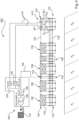
- the Figure 1 shows a charging station 100, which is connected to an electrical supply network 102 via a network connection point NAP.
- a supply facility is required 104 provided.
- the supply device 104 comprises at least one transformer 106 and a rectifier unit 108 connected downstream of the transformer.
- the transformer 106 is connected directly to the supply network 102 via the network connection point NAP and thereby transforms a first alternating voltage, in particular the network voltage, into one suitable for the rectifier unit 108 second alternating voltage.
- a medium-voltage transformer is shown here, which transforms the mains voltage from 20 kV down to 400 V alternating voltage.
- the rectifier unit 108 shown generates a direct voltage from the second alternating voltage at a direct voltage output and can therefore provide power that is drawn from the supply network.
- the supply device 104 is therefore intended in particular for connecting to an electrical supply network 102 and for supplying the charging station with electrical power.
- Charging station 100 shown further includes five charging terminals 116, a supply terminal 114 and an additional power terminal 118, which can also be referred to as terminals for simplicity. A detailed description of the terminals mentioned follows in the description Figure 2 .
- the terminals (114, 116, 118) of the charging station 100 are arranged next to each other at the parking spaces P1 to P6. This means that several electric vehicles can be charged and are parked in parking spaces P1 - P6 for charging.
- the parking spaces are to be understood as particularly illustrative and are not intended to limit the number of vehicles to be charged to six; in principle, 10 vehicles can also be charged at the charging station shown.
- a supply terminal 114 is provided in order to pass on the power provided by the supply device 104 to the terminals in the form of a direct voltage.
- the supply terminal is electrically connected to the rectifier unit 108 via a main supply line 110.
- a main supply input 112 is attached to the supply terminal 114. Power can thus be obtained from the supply device 104 via the main supply input 112. The power obtained in this way is then distributed to the other terminals (116, 118) via several supply lines 130.
- the supply terminal 114 is therefore designed to receive electrical power from the supply device and to forward it to the charging terminals 116 and possibly additional power terminals 118.
- the charging station 100 has several charging terminals 116 for charging at least one electric vehicle.
- Each charging terminal includes a supply input 120 and a charging output 122.
- the supply input 120 is set up to obtain electrical power from the supply device 104 by providing connections at the supply input 120 with which the terminals can be connected to one another at the supply inputs.
- the Figure 1 shows that, for example, two charging terminals 116 are arranged on the left side and three charging terminals as well as the additional power terminal 118 are arranged on the right side, relative to the supply terminal 114. All terminals are electrically coupled to one another at the respective supply inputs 120 via supply lines 130. In the example shown, a section of the supply line 130 is present between two adjacent terminals, so that there is no single, continuous long supply line, as is usual with a power busbar or a bus line.
- the charging terminals can directly obtain the electrical power forwarded from the supply terminal 114 via the supply lines 130.
- the charging terminals 116 and additional power terminals 118 can also indirectly obtain the forwarded power from the supply terminal 114 via another terminal.
- the supply inputs can then also be viewed as supply outputs for a neighboring terminal.
- a charging output 122 with one or more charging connections is also provided at each charging terminal 116, which are used to deliver a charging current for charging a connected electric vehicle.
- a charging output 122 with one or more charging connections is also provided at each charging terminal 116, which are used to deliver a charging current for charging a connected electric vehicle.
- two electric vehicles can be connected to the two charging outputs of one of the five charging terminals 116.
- At least one DC current controller 126 is arranged in each of the charging terminals 116 in order to generate one current controller current per current controller or DC-DC converter. The currents generated in this way are then used to charge an electric vehicle connected to a charging output 122 of one of the charging terminals.
- An additional power terminal is provided in the charging station as a further terminal.
- This additional power terminal is used to generate and provide additional power for charging electric vehicles. It has no charging ports on one Charging output for charging an electric vehicle. Additional electricity is provided, for example, if a charging terminal is too busy. Excessive utilization can occur, for example, if the power demand of an electric car exceeds the maximum power that a terminal can generate. In a specific example, if a vehicle requires a charging current of 400 A and the charging terminal can only provide a maximum of 100 A.
- the additional current terminal is therefore provided for generating one or more additional additional currents, in particular current controller currents, in order to provide them to at least one charging terminal, the additional current terminal itself not having a charging output.
- the charging outputs 122 of the charging terminals are connected to one another at exchange connections via electrical exchange lines 128 in order to be able to exchange the generated current controller currents with one another. It is also provided that the supply terminal 114 and the additional power terminal 118 are electrically coupled on the output side to the charging terminals 116 via the exchange lines 128. For example, an electric vehicle parked in the parking lot P1 can receive a charging current that was at least partially generated by a DC controller from another charging terminal or an additional power terminal.
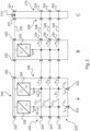
- the Figure 2 shows a more detailed embodiment of a charging terminal A, an additional power terminal B and a supply terminal C which corresponds to the charging terminal 116, the additional power terminal 118 and the supply terminal 114, respectively Figure 1 are equivalent to.
- the charging terminal A has a supply input 200 and a charging output 202.
- two connection means 220 are arranged, which can be designed, for example, as a plug connector. Any additional charging terminal, an additional power terminal or a supply terminal can be connected to these connection means in order to connect the supply inputs of these terminals to one another.
- Each charging terminal A has two DC controllers 226, which are arranged parallel to one another between the supply input 200 and the charging output 202, and each impress a current controller current I S1 or I S2 into a cross line QL 1 and QL 2 arranged at the charging output.
- Each DC controller 226 is assigned exactly one charging connection 222 and a cross line QL 1 or QL 2 for each DC controller.
- n cross lines are used to Connect the DC controller to the charging port.
- the terminal is constructed from two cross lines QL 1 , QL 2 and two charging connections 222.
- first and a second connection area are indicated for the charging terminal A with the arrows 204 and 206, each of which has several, in particular the same number, exchange connections 224.
- the terminals can be connected via essentially parallel exchange lines 228, which are in the Figure 2 are shown in dashed lines.
- a longitudinal line LL 1 , LL 2 , LLs is also provided within the terminal in order to electrically connect the respective exchange connection 224 of one connection area 204, 206 with one exchange connection of the other connection area 206, 204, so that at m exchange connections of one connection area m longitudinal lines are provided.
- the longitudinal lines run in particular electrically parallel to one another.
- the specific design of the charging terminal A has, for example, three exchange connections in the connection area 206, which means that three longitudinal lines are provided.
- the longitudinal lines LL 1 , LL 2 and LLs connect the two connection areas 204 and 206.
- each longitudinal line LL 1 , LL 2 , LL 3 is directly connected via a connection node to at least one of the transverse lines QL 1 , QL 2 .
- each charging terminal itself can have a control unit or a higher-level control unit can take over the control of the controllable switching means.
- a mixed form of control units in each loading terminal and a higher-level control unit can also be implemented. However, this is not in the Figure 2 shown.
- the controllable switching means in the charging terminal A are in the Figure 2 the three exchange switching means A1, A2 and A3 are shown, each of which is electrically connected to an exchange connection 224 in order to allow the exchange of at least one current controller current via the exchange means with an adjacent charging terminal or additional power terminal steer.
- Another controllable switching means is the bridge switching means B1, which electrically connects two DC controllers in a charging terminal, in the present case via the two cross lines QL 1 and QL 2 , in order to control a superposition of the current controller currents I S1 and I S2 of the two DC controllers 226.
- a charging switching means C1 or C2 is arranged at a charging connection 222 in order to control either the delivery of the charging current I L1 or I L2 .
- charging terminal A shown form a charging current I L1 or I L2 from a current controller current I S1 or I S2 or several current controller currents and even obtain or deliver further current controller currents via the replacement connections.
- the DC current controller 226 is connected to all replacement connections 224 in the additional power terminal B in order to provide the current controller current I S3 to all replacement lines 228.
- the additional power terminal is therefore prepared to deliver additional power.
- three exchange switching means A1, A2 and A3 are provided in the additional power terminal, similar to the charging terminal A. These can also be used to forward current controller currents from neighboring terminals if, for example, the current controller 226 in the additional power terminal does not generate any current I S3 .
- supply terminal C has an additional main supply input 212 and two supply outputs 221, which are identical in construction to the supply inputs of terminals A and B.
- the supply outputs 221 are used to forward the power received from the supply device to the charging terminals and, if necessary, to the at least one additional power terminal, in particular to forward power to all charging terminals.
- the supply terminal C similar to the terminals A and B, also has exchange connections 224 in order to be connected to at least one connection area 208 or 210 with an adjacent charging terminal and / or possibly additional power terminal in order to be able to pass at least one current controller current through the supply terminal .
- a charging station can be constructed in any modular way, like a type of box, from terminals A, B and/or C.
- the invention was described particularly for charging terminals and additional power terminals, each of which has one or more DC controllers.
- This description and the advantages mentioned can also be applied to variants that use one or more current controller terminals instead of one or more DC controllers.
- two current controller terminals can be provided in the charging terminal A or 116, each of which receives a current controller current from the supply device 104 and provides it as a current controller current I S1 or I S2 .
- a direct current controller can be provided in the supply device 104 for each current controller terminal, as well as a connecting line to the supply device 104 according to Figure 1 .
- One, several or all charging terminals 116 can be provided with current controller terminals instead of DC current controllers 126. The same applies analogously to the additional power terminal 118 or any other additional power terminals.
- the charging station 400 Figure 4 differs from the charging station 100 Figure 1 in that the charging terminal 416 shown on the far right has two current controller terminals 427 instead of two DC current controllers 126.
- the current controller terminals 427 each receive a current controller current via an individual line 410, each of which is connected to a DC controller 126 in the supply device 404.
- the current controller terminals 427 therefore essentially only provide one current controller current, which was generated by one of the two DC controllers 126.
- the provision here also takes place on cross lines Q L1 or Q L2 , the further interconnection of which is in the Figure 2 is described in more detail. This also applies here to the variant Figure 4 applicable.
- the two individual lines 410 can alternatively also be routed via the supply terminal 114 and then via supply inputs 120.
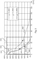
- the Figure 3 shows a diagram with three different charging current curves I 1 , I 2 and I 3 in percent for three different vehicle classes AM1, AM2 and AM3.
- the ordinate shows the utilization of the charging station in percent, whereby in this example the charging terminal can deliver a charging current of 100 A at 100% utilization, which corresponds to the maximum current of vehicle class AM1.
- the time t is shown in minutes on the abscissa.
- vehicle class AM3 requires a charging voltage that is approximately twice as high as vehicle classes AM1 and AM2.
- the 400% charging current that comes in Figure 3 Initially shown for the vehicle type AM3 correspond to around 800% charging power, based on the vehicle class AM1.
- 80% SOC points of the state of charge which indicate a state of charge of 80% based on a full charge, are reached at very different times.
- vehicle class AM1 could correspond to a small car class, car class AM2 to a premium class and class AM3 to a super sports car class.
- the charging characteristics or current characteristics I 1 , I 2 and I 3 take a different course.
- Two current controllers can work in parallel (double current) or in series (double voltage).
- a relatively constant charging current of 100 A is required for around 20 minutes, so that a charging terminal with a DC controller is at 100% capacity.
- a current controller that can deliver 100A would be sufficient here.
- the DC controllers do not have to be dimensioned to a charging current of, for example, 400 A for the super sports car, the proposed charging terminal can obtain DC controller currents via neighboring terminals in order to also be able to charge a super sports car in the first charging area AO1. In the AO2 charging area, the power requirement of the super sports car then drops relatively quickly. DC controllers that are not required can then be released or switched off or switched over by the control unit depending on the power requirements of the vehicle - if they are no longer needed.
- the charging station could charge the super sports car in the first 7 minutes to 300% capacity with seven or eight DC controllers at the same time at around 50 A each.
- This large number is necessary because the super sports car mentioned as an example requires twice as high a charging voltage, so that instead of around 100A, only around 50A can be supplied per DC controller.
Landscapes
- Engineering & Computer Science (AREA)
- Power Engineering (AREA)
- Transportation (AREA)
- Mechanical Engineering (AREA)
- Charge And Discharge Circuits For Batteries Or The Like (AREA)
- Electric Propulsion And Braking For Vehicles (AREA)
- Dc-Dc Converters (AREA)
Claims (14)
- Station de charge (100) pour la charge de plusieurs véhicules électriques, en particulier de véhicules automobiles électriques, comprenant :- un dispositif d'alimentation (104), en particulier pour le raccordement à un réseau d'alimentation (102) électrique, pour l'alimentation de la station de charge en une puissance électrique,- plusieurs bornes de charge (116) pour la charge respectivement d'au moins un véhicule électrique, et chaque borne de charge comprend-- une entrée d'alimentation (120) pour tirer de la puissance électrique du dispositif d'alimentation,-- une sortie de charge (122) avec une ou plusieurs prises de charge pour délivrer respectivement un courant de charge pour la charge respectivement d'un véhicule électrique raccordé, et-- au moins un régulateur de courant continu (126) agencé entre l'entrée d'alimentation et la sortie de charge afin de générer, à partir de la puissance électrique du dispositif d'alimentation respectivement un courant de régulateur de courant, ou en variante au moins une borne de régulateur de courant agencée entre l'entrée d'alimentation et la sortie de charge afin de fournir un courant de régulateur de courant généré en dehors de la borne de charge par un régulateur de courant continu, en particulier le courant de régulateur de courant généré dans le dispositif d'alimentation, dans lequel, dans chaque cas-- chaque courant de charge (IL1, IL2) est formé à partir d'un courant de régulateur de courant ou de plusieurs courants de régulateur de courant (IS1, IS2, IS3), et dans laquelle-- les bornes de charge sont reliées entre elles au niveau de prises d'échange par le biais de conduites d'échange (128) électriques afin d'échanger entre elles des courants de régulateur de courant par leur biais, dans laquelle
la station de charge (100) présente au moins une borne d'alimentation (114), pour la réception de puissance électrique du dispositif d'alimentation (104) et pour la transmission aux bornes de charge, et chaque borne d'alimentation comprend-- une entrée d'alimentation principale (112) reliée par le biais d'une conduite d'alimentation principale (110), au dispositif d'alimentation afin de tirer par son biais de la puissance du dispositif d'alimentation, et-- au moins une sortie d'alimentation afin de transmettre par son biais la puissance tirée du dispositif d'alimentation aux bornes de charge, et dans laquelle
des prises d'échange correspondant aux prises d'échange des bornes de charge au niveau d'une première et seconde zone de liaison de la borne d'alimentation sont présentes afin d'être reliées au niveau d'au moins une zone de liaison à respectivement une borne de charge contiguë afin de pouvoir faire passer au moins un courant de régulateur de courant par la borne d'alimentation. - Station de charge selon la revendication 1,
caractérisée en ce que
la station de charge (100) présente au moins une borne de courant supplémentaire (118) pour la fourniture, en particulier la génération, d'un ou de plusieurs courants de régulateur de courant supplémentaires afin de le(s) fournir à au moins une borne de charge, dans laquelle la borne de courant supplémentaire elle-même ne présente aucune sortie de charge, et chaque borne de courant supplémentaire comprend- une entrée d'alimentation correspondant à l'entrée d'alimentation d'une borne de charge pour tirer de la puissance électrique du dispositif d'alimentation,- au moins une prise d'échange correspondant à la prise d'échange d'une borne de charge pour la transmission de courants de régulateur de courant à au moins une des bornes de charge, et- au moins un régulateur de courant continu agencé entre l'entrée d'alimentation et l'au moins une prise d'échange et correspondant au ou à un régulateur de courant continu de la borne de charge afin de générer à partir de la puissance électrique du dispositif d'alimentation respectivement un courant de régulateur de courant, ou en variante au moins une borne de régulateur de courant agencée entre l'entrée d'alimentation et l'au moins une prise d'échange et correspondant à la ou une borne de régulateur de courant de la borne de charge afin de fournir un courant de régulateur de courant généré en dehors de la borne de courant supplémentaire d'un régulateur de courant continu, en particulier le courant de régulateur de courant généré dans le dispositif d'alimentation, dans lequel en particulier- le régulateur de courant continu ou la borne de régulateur de courant de la borne de courant supplémentaire est relié(e) à toutes les prises d'échange de la borne de courant supplémentaire afin de fournir le courant de régulateur de courant à toutes les conduites d'échange. - Station de charge selon la revendication 1 ou 2,
caractérisée en ce que- au moins une des sorties d'alimentation est préparée afin de transmettre la puissance tirée par le dispositif d'alimentation à au moins une ou l'au moins une borne de courant supplémentaire ou afin de transmettre de la puissance à toutes les bornes de charge. - Station de charge selon l'une quelconque des revendications précédentes,
caractérisée en ce que les bornes de charge ou au moins une ou l'au moins une borne de courant supplémentaire- présentent des entrées d'alimentation (200) de même construction de sorte que respectivement deux des entrées d'alimentation soient reliées entre elles afin de transmettre ainsi respectivement un courant d'alimentation électrique ou une partie de celui-ci d'une entrée d'alimentation à une entrée d'alimentation contiguë de sorte que chaque borne de charge ou chaque borne de courant supplémentaire reçoive son courant d'alimentation d'une borne de charge contiguë, borne de courant supplémentaire ou borne d'alimentation, ou que- les entrées d'alimentation ou les prises d'échange présentent respectivement des moyens de raccordement de même construction (220, 224), en particulier des connecteurs enfichables, afin de relier entre elles parmi les bornes de charge, ou bornes de courant supplémentaire et la borne d'alimentation respectivement au choix deux de manière échangeable, en particulier de sorte que toutes les bornes de charge reliées entre elles, ou bornes de courant supplémentaire et la borne d'alimentation forment dans l'ensemble une structure modulaire, en particulier la borne d'alimentation présente des prises d'échange ou sorties d'alimentation adaptées à celle-ci. - Station de charge selon l'une quelconque des revendications précédentes,
caractérisée en ce que- chaque borne de charge présente au moins un moyen de commutation commandable à partir de la liste présentant-- un moyen de commutation d'échange (A1, A2, A3) qui est relié électriquement à respectivement une prise d'échange afin de commander l'échange au moins d'un courant de régulateur de courant par le biais du moyen d'échange avec une borne de charge ou borne de courant supplémentaire contigüe,-- un moyen de commutation de charge (C1, C2) qui est relié électriquement à respectivement une prise de charge afin de commander la délivrance d'un courant de charge à la prise de charge, et-- un moyen de commutation de pont (B1) qui est relié électriquement à deux régulateurs de courant continu ou bornes de régulateur de courant dans une borne de charge, en particulier par le biais de deux conduites transversales, afin de commander une superposition des courants de régulateur de courant des deux régulateurs de courant continu ou bornes de régulateur de courant. - Station de charge selon l'une quelconque des revendications précédentes,
caractérisée en ce que- chaque borne de charge présente une première et une seconde zone de liaison (204, 206) avec respectivement plusieurs, en particulier un nombre égal de prises d'échange (224),-- pour chaque prise d'échange d'une des zones de liaison une conduite longitudinale (LL1, LL2, LL3) est prévue afin de relier électriquement la prise d'échange respective de l'une zone de liaison (204) à respectivement une prise d'échange de l'autre zone de liaison (206) de sorte que pour m prises d'échange de l'une zone de liaison m conduites longitudinales soient prévues, lesquelles s'étendent en particulier électriquement parallèlement les unes aux autres,- à chaque régulateur de courant continu (226) ou borne de régulateur de courant est associée une prise de charge (222) et pour chaque régulateur de courant continu ou chaque borne de régulateur de courant est prévue une conduite transversale (QL1, QL2) afin de relier le régulateur de courant continu ou la borne de régulateur de courant à la prise de charge de sorte que pour un nombre n de régulateurs de courant continu ou un nombre n de bornes de régulateur de courant un nombre n de conduites transversales soient prévues, et dans laquelle au moins une configuration est prévue à partir de la liste présentant que-- chaque conduite longitudinale est reliée directement par le biais d'un noeud de liaison à au moins une de la conduite transversale,-- précisément n-1 moyens de commutation de pont sont prévus afin de relier électriquement respectivement deux conduites transversales,-- chaque conduite transversale menant au moyen de commutation de charge ne présente aucun autre moyen de commutation,-- dans chaque borne de charge une conduite longitudinale est prévue plutôt que des conduites transversales de sorte que s'applique : m=n+1, et-- une conduite longitudinale dans la borne de charge--- est reliée directement à deux conduites transversales respectivement par le biais d'un noeud de liaison, avec un des moyens de commutation de pont entre les deux noeuds de liaison, ou--- est reliée à une seule conduite transversale par le biais d'un noeud de liaison sans présenter dans la borne de charge de moyen de commutation de pont. - Station de charge selon l'une quelconque des revendications précédentes,
caractérisée en ce que- au moins une unité de commande est prévue, laquelle est préparée afin de commander les bornes de charge (116) de telle manière qu'un courant de charge d'une borne de charge puisse être formé à partir d'un courant de régulateur de courant ou de plusieurs courants de régulateur de courant, dans laquelle- le courant de charge-- est formé à partir de courants de régulateur de courant d'au moins un régulateur de courant continu ou borne de régulateur de courant de la même borne de charge,-- est formé à partir de courants de régulateur de courant d'au moins un régulateur de courant continu ou borne de régulateur de courant au moins d'une autre borne de charge,-- est formé à partir de courants de régulateur de courant d'au moins un régulateur de courant continu et au moins une borne de régulateur de courant de plusieurs bornes de charge, ou-- est formé à partir d'une combinaison des courants de régulateur de courant cités. - Station de charge selon l'une quelconque des revendications précédentes,
caractérisée en ce que- la station de charge (100) est constituée ainsi, en particulier est commandable par le biais d'une ou de l'au moins une unité de commande de telle manière que-- au moins un moyen de commutation d'échange d'une borne de charge, à laquelle un véhicule électrique à charger est raccordé, puisse être fermé afin de tirer ainsi au moins un courant de régulateur de courant d'au moins une borne de charge contiguë afin de générer ainsi un courant de charge pour le véhicule électrique à charger et/ou-- au moins un moyen de commutation de pont de la borne de charge, auquel est raccordé le véhicule électrique, puisse être fermé afin d'assembler ainsi plusieurs courants de régulateur de courant à partir de plusieurs régulateurs de courant continu ou bornes de régulateur de courant agencées dans la borne de charge pour la génération du courant de charge, et/ou-- au moins un moyen de commutation d'échange au moins d'une borne de charge contiguë ou autre et/ou bornes de courant supplémentaire contigües ou autres puisse être fermé afin de tirer et assembler ainsi au moins un courant de régulateur de courant à partir de bornes de charge contigües ou autres ou bornes de courant supplémentaire pour la génération du courant de charge et/ou-- au moins un moyen de commutation de pont au moins d'une borne de charge contiguë ou autre puisse être fermé afin de tirer au moins un courant de régulateur de courant à partir de plusieurs régulateurs de courant continu agencés dans la borne de charge contigüe ou bornes de régulateur de courant pour la génération du courant de charge par le biais d'au moins une conduite d'échange. - Station de charge selon l'une quelconque des revendications précédentes,
caractérisée en ce que- au moins un moyen de commutation d'échange et au moins un moyen de commutation de pont sont câblés de sorte que-- un courant de régulateur de courant d'un régulateur de courant continu ou d'une borne de régulateur de courant d'une première borne de charge ou d'une première borne de courant supplémentaire puisse circuler par le biais d'une première conduite longitudinale et un ou l'au moins un moyen de commutation d'échange dans une seconde borne de charge,-- le courant de régulateur de courant puisse circuler dans la seconde borne de charge par le biais d'un premier noeud de liaison et une première conduite transversale vers une seconde conduite longitudinale et-- le courant de régulateur de courant puisse circuler par le biais d'un deuxième noeud de liaison, un ou l'au moins un moyen de commutation de pont et un troisième noeud de liaison à une seconde conduite transversale de la seconde borne de charge,-- afin d'y être assemblé avec au moins un autre courant de régulateur de courant pour la génération d'un courant de charge, en particulier-- afin de charger un véhicule électrique raccordé à la seconde conduite transversale. - Station de charge selon l'une quelconque des revendications précédentes,
caractérisée en ce que- la station de charge est constituée ainsi, est commandable en particulier par le biais d'une ou l'au moins une unité de commande de telle manière que- les moyens de commutation commandables puissent être commutés de telle manière qu'un courant de charge puisse être formé à partir d'au moins 3 courants de régulateur de courant, de préférence d'au moins 5 courants de régulateur de courant, en particulier d'au moins 7 courants de régulateur de courant. - Station de charge selon l'une quelconque des revendications précédentes,
caractérisée en ce que- une ou l'unité de commande peut commander la génération des courants de charge, en particulier le nombre de courants de régulateur de courant fournis à une prise de charge, en fonction d'un critère de commande, sélectionné à partir de la liste présentant- un type d'un véhicule électrique raccordé à la prise de charge,- un état d'accumulateur du véhicule électrique raccordé à la prise de charge,- un besoin en courant dépendant de l'état d'accumulateur du véhicule électrique raccordé,- une exigence de courant du véhicule électrique raccordé,- un souhait de charge indiqué par un utilisateur pour la charge du véhicule électrique raccordé à la prise de charge et- un nombre de régulateurs de courant continu et/ou de bornes de régulateur de courant disponibles pour la génération ou la fourniture de courants de régulateur de courant pour l'assemblage pour la génération d'un courant de charge. - Procédé de charge de plusieurs véhicules électriques, en particulier véhicules automobiles électriques, au moyen d'une station de charge, comprenant les étapes suivantes :- l'alimentation de la station de charge en une puissance électrique par le biais d'un dispositif d'alimentation de la station de charge ;- la charge respectivement au moins d'un véhicule électrique au moyen d'une des plusieurs bornes de charge de la station de charge avec les étapes suivantes :-- le tirage de la puissance électrique du dispositif d'alimentation à une entrée d'alimentation de la borne de charge,-- la délivrance respectivement d'un courant de charge pour la charge du véhicule électrique raccordé à une sortie de charge avec une ou plusieurs prises de charge, dans lequel le véhicule électrique est raccordé à une des prises de charge, à laquelle le courant de charge est délivré, et dans lequel-- au moins un régulateur de courant continu agencé entre l'entrée d'alimentation et la sortie de charge génère à partir de la puissance électrique du dispositif d'alimentation respectivement un courant de régulateur de courant, ou au moins une borne de régulateur de courant agencée entre l'entrée d'alimentation et la sortie de charge fournit respectivement un courant de régulateur de courant généré par respectivement un courant de régulateur de courant généré en dehors de la borne de charge par un régulateur de courant continu, en particulier le courant de régulateur de courant généré dans le dispositif d'alimentation, et dans chaque cas-- le courant de charge est formé à partir d'un courant de régulateur de courant ou de plusieurs courants de régulateur de courant, et dans lequel-- les bornes de charge sont reliées entre elles au niveau de prises d'échange par le biais de conduites d'échange électriques, et au choix-- échangent des courants de régulateur de courant entre elles par leur biais, dans lequel-- le procédé utilise une station de charge (100) qui présente au moins une borne d'alimentation (114) pour la réception de puissance électrique du dispositif d'alimentation (104) et pour la transmission à la borne de charge, et chaque borne d'alimentation comprend--- une entrée d'alimentation principale (112) reliée, par le biais d'une conduite d'alimentation principale (110), au dispositif d'alimentation afin de tirer par son biais de la puissance du dispositif d'alimentation, et--- au moins une sortie d'alimentation afin de transmettre par son biais la puissance tirée du dispositif d'alimentation aux bornes de charge, et dans lequel--- des prises d'échange correspondant aux prises d'échange des bornes de charge sont présentes au niveau d'une première et seconde zone de liaison de la borne d'alimentation afin d'être reliées au niveau d'au moins une zone de liaison à respectivement une borne de charge contiguë afin de pouvoir faire passer au moins un courant de régulateur de courant par la borne d'alimentation.
- Procédé selon la revendication 12, caractérisé en ce qu'une station de charge selon l'une quelconque des revendications 1 à 11 est utilisée.
- Procédé selon la revendication 12 ou 13, caractérisé en ce que- au moins un moyen de commutation d'échange d'une borne de charge, à laquelle un véhicule électrique à charger est raccordé, est fermé, et
au moins un courant de régulateur de courant est tiré ainsi par au moins une borne de charge contiguë, et ainsi un courant de charge est généré pour le véhicule électrique à charger et/ou- au moins un moyen de commutation de pont de la borne de charge, à laquelle le véhicule électrique est raccordé, est fermé, et ainsi plusieurs courants de régulateur de courant sont assemblés ou superposés à partir de plusieurs régulateurs de courant continu ou bornes de régulateur de courant agencés dans la borne de charge pour la génération du courant de charge, et/ou- au moins un moyen de commutation d'échange d'au moins une borne de charge contiguë ou autre et/ou borne de courant supplémentaire contigüe ou autre est fermé et ainsi, au moins un courant de régulateur de courant est tiré et assemblé ou superposé à partir de bornes de charge contiguës ou autres ou bornes de courant supplémentaires pour la génération du courant de charge et/ou- au moins un moyen de commutation de pont au moins d'une borne de charge contigüe ou autre est fermé, et ainsi au moins un courant de régulateur de courant est tiré à partir de plusieurs régulateurs de courant continu ou bornes de régulateur de courant agencées dans la borne de charge contiguë pour la génération du courant de charge par le biais d'au moins une conduite d'échange.
Applications Claiming Priority (2)
| Application Number | Priority Date | Filing Date | Title |
|---|---|---|---|
| DE102017116887.7A DE102017116887A1 (de) | 2017-07-26 | 2017-07-26 | Ladestation mit dynamischer Ladestromverteilung |
| PCT/EP2018/070293 WO2019020747A1 (fr) | 2017-07-26 | 2018-07-26 | Station de charge à distribution dynamique de courant de charge |
Publications (3)
| Publication Number | Publication Date |
|---|---|
| EP3659232A1 EP3659232A1 (fr) | 2020-06-03 |
| EP3659232B1 true EP3659232B1 (fr) | 2024-03-06 |
| EP3659232C0 EP3659232C0 (fr) | 2024-03-06 |
Family
ID=63042024
Family Applications (1)
| Application Number | Title | Priority Date | Filing Date |
|---|---|---|---|
| EP18746679.2A Active EP3659232B1 (fr) | 2017-07-26 | 2018-07-26 | Station de charge à distribution dynamique de courant de charge |
Country Status (10)
| Country | Link |
|---|---|
| US (1) | US11264798B2 (fr) |
| EP (1) | EP3659232B1 (fr) |
| JP (1) | JP7042326B2 (fr) |
| KR (1) | KR20200032173A (fr) |
| CN (1) | CN110999009B (fr) |
| BR (1) | BR112020001498A2 (fr) |
| CA (1) | CA3069797C (fr) |
| DE (1) | DE102017116887A1 (fr) |
| RU (1) | RU2730914C1 (fr) |
| WO (1) | WO2019020747A1 (fr) |
Families Citing this family (22)
| Publication number | Priority date | Publication date | Assignee | Title |
|---|---|---|---|---|
| DE102017116886A1 (de) * | 2017-07-26 | 2019-01-31 | Wobben Properties Gmbh | Ladestation mit dynamischer Ladestromverteilung |
| DE102018212740A1 (de) * | 2018-07-31 | 2020-02-06 | Ads-Tec Gmbh | Ladestation für Elektroautos |
| FR3095992B1 (fr) * | 2019-05-14 | 2022-01-21 | Hadi Moussavi | Systeme et procede de charge en energie electrique de vehicules automobiles |
| CN112217406A (zh) * | 2019-07-11 | 2021-01-12 | 台达电子工业股份有限公司 | 应用于固态变压器架构的电源装置及三相电源系统 |
| DE102019217784A1 (de) * | 2019-11-19 | 2021-05-20 | Volkswagen Aktiengesellschaft | Ladeinfrastruktur zur Ladung eines Kraftfahrzeugs |
| FR3110787B1 (fr) * | 2020-05-20 | 2022-07-08 | Ineo Urban Transp Solutions | Station de recharge pour flottes de vehicules electriques |
| DE102020209653A1 (de) | 2020-07-30 | 2022-02-03 | Volkswagen Aktiengesellschaft | Elektrisches Ladesystem zum Laden eines elektrischen Akkumulators |
| FR3113205B1 (fr) * | 2020-08-03 | 2024-08-16 | Hager Electro Sas | Circuit de distribution électrique pour parc de stationnement de véhicules |
| US12249828B2 (en) * | 2020-08-24 | 2025-03-11 | Hitachi, Ltd. | Power conversion device |
| DE102020134458A1 (de) * | 2020-12-21 | 2022-06-23 | innogy eMobility Solutions GmbH | Anordnung zur Integration in eine Ladevorrichtung für wenigstens ein Elektrofahrzeug |
| KR102488730B1 (ko) * | 2021-01-26 | 2023-01-17 | 주식회사 에프이씨 | 다중접속스위치 및 이를 포함하는 충전위치 선택형 전기자동차 충전시스템 |
| KR102415686B1 (ko) * | 2021-01-26 | 2022-07-01 | 주식회사 에프이씨 | 충전위치 선택형 전기자동차 충전 방법 및 시스템 |
| US12441210B2 (en) * | 2021-06-25 | 2025-10-14 | Zoox, Inc. | Fleet charging station architecture |
| EP4112362A1 (fr) * | 2021-06-29 | 2023-01-04 | Ekoenergetyka - Polska Sp. z o.o. | Borne pour recharger des véhicules électriques avec stockage d'énergie électrochimique |
| US20230117407A1 (en) * | 2021-10-19 | 2023-04-20 | Chargepoint, Inc. | Dynamic allocation of power modules for charging electric vehicles |
| WO2025178507A1 (fr) * | 2024-02-22 | 2025-08-28 | Общество с ограниченной ответственностью Научно-производственное объединение "Энергия-Исследование" | Station de chargement pour accumulateurs de traction de véhicules électriques |
| AT528145A1 (de) | 2024-03-21 | 2025-10-15 | AVL SET GmbH | Ladestation zur gleichzeitigen Ladung mehrerer elektrisch angetriebener Fahrzeuge |
| DE102024108715A1 (de) | 2024-03-27 | 2025-10-02 | Amperfied GmbH | Flexibles DC-Ladesystem für mehrere Ladesäulen |
| EP4653251A1 (fr) * | 2024-05-24 | 2025-11-26 | ABB E-mobility B.V. | Unité de distribution de charge et système de charge comprenant l'unité de distribution de charge |
| LU507414B1 (de) * | 2024-06-04 | 2025-12-04 | Phoenix Contact Gmbh & Co | Batterieladestation mit mindestens zwei Ladeanschlüssen |
| DE102024117491A1 (de) | 2024-06-20 | 2025-12-24 | Innofas Gmbh | Ladesystem für Elektrofahrzeuge und Verfahren zum Laden von Elektrofahrzeugen |
| TWI902436B (zh) * | 2024-09-04 | 2025-10-21 | 台達電子工業股份有限公司 | 電動車直流充電系統 |
Citations (1)
| Publication number | Priority date | Publication date | Assignee | Title |
|---|---|---|---|---|
| JP2013027236A (ja) * | 2011-07-25 | 2013-02-04 | Toyota Motor Corp | バッテリの充電システムおよび車両の充電システム |
Family Cites Families (36)
| Publication number | Priority date | Publication date | Assignee | Title |
|---|---|---|---|---|
| JP3214044B2 (ja) * | 1992-03-27 | 2001-10-02 | 株式会社明電舎 | 充電装置 |
| US5926004A (en) | 1997-10-10 | 1999-07-20 | Schott Power Systems Incorporated | Method and apparatus for charging one or more electric vehicles |
| US7256516B2 (en) * | 2000-06-14 | 2007-08-14 | Aerovironment Inc. | Battery charging system and method |
| JP2007323843A (ja) * | 2006-05-30 | 2007-12-13 | Ebara Ballard Corp | 燃料電池の運転方法及び燃料電池システム |
| JP2008199752A (ja) * | 2007-02-09 | 2008-08-28 | Kyushu Electric Power Co Inc | 充電装置 |
| CN101483350A (zh) | 2009-02-28 | 2009-07-15 | 上海中上汽车科技有限公司 | 一种电容或动力电池牵引型电车充电基站系统 |
| NL2004279C2 (en) | 2010-02-22 | 2011-08-23 | Epyon B V | System, device and method for exchanging energy with an electric vehicle. |
| NL2004350C2 (en) | 2010-03-05 | 2011-09-06 | Epyon B V | System, devices and method for charging a battery of an electric vehicle. |
| KR101009485B1 (ko) | 2010-04-20 | 2011-01-19 | (주)모던텍 | 유니버셜 충전 장치 |
| JP5647057B2 (ja) | 2010-05-19 | 2014-12-24 | 株式会社日立製作所 | 充電装置、充電制御ユニット及び充電制御方法 |
| NL2004746C2 (en) | 2010-05-19 | 2011-11-22 | Epyon B V | Charging system for electric vehicles. |
| KR20110137675A (ko) | 2010-06-17 | 2011-12-23 | (주)시그넷시스템 | 전기구동 차량의 급속충전 및 충전용량 조절이 가능한 충전 스테이션 |
| NL2005026C2 (en) | 2010-07-05 | 2012-01-09 | Epyon B V | Charger for a battery, plurality of coupled chargers and method of operating. |
| US8952656B2 (en) | 2011-02-04 | 2015-02-10 | Atieva, Inc. | Battery charging station |
| WO2012117694A1 (fr) * | 2011-02-28 | 2012-09-07 | 株式会社日立製作所 | Convertisseur de puissance électrique |
| DE102011079430A1 (de) * | 2011-07-19 | 2013-01-24 | Siemens Aktiengesellschaft | DC-Ladestation zum Aufladen mehrerer Energiespeichereinrichtungen |
| US8810198B2 (en) | 2011-09-02 | 2014-08-19 | Tesla Motors, Inc. | Multiport vehicle DC charging system with variable power distribution according to power distribution rules |
| JP2013110870A (ja) * | 2011-11-21 | 2013-06-06 | Panasonic Corp | 電力変換装置 |
| KR101585117B1 (ko) * | 2011-12-08 | 2016-01-21 | 가부시키가이샤 에네르기 오요 기쥬츠켄큐쇼 | 급속충전용 전원 시스템 |
| NL2008058C2 (en) | 2011-12-29 | 2013-07-03 | Epyon B V | Method, system and charger for charging a battery of an electric vehicle. |
| JP5723811B2 (ja) | 2012-03-13 | 2015-05-27 | 株式会社トライネット | 電気自動車の充電装置及び充電システム |
| WO2013137501A1 (fr) * | 2012-03-14 | 2013-09-19 | (주)시그넷시스템 | Poste de recharge |
| DE102012218738A1 (de) | 2012-10-15 | 2014-04-17 | Siemens Aktiengesellschaft | Ladesystem und Verfahren zum gleichzeitigen Laden mehrerer Fahrzeugbatterien |
| PT2871090T (pt) | 2013-11-06 | 2020-12-24 | Abb Schweiz Ag | Carregador para veículos elétricos com arbitragem de conversor de energia distribuída |
| CN104810894B (zh) | 2015-05-08 | 2017-04-05 | 山东鲁能智能技术有限公司 | 一种电动汽车分体式直流充电桩、系统及方法 |
| JP6548262B2 (ja) | 2015-12-25 | 2019-07-24 | ニチコン株式会社 | 電動車のための充電システム |
| CN105449791A (zh) | 2016-01-07 | 2016-03-30 | 山东泰开自动化有限公司 | 电动汽车直流智能充电桩 |
| CN105480110B (zh) | 2016-01-12 | 2019-02-19 | 沈阳工业大学 | 智能充电桩及智能充电方法 |
| DE102016103011A1 (de) | 2016-02-22 | 2017-08-24 | Dr. Ing. H.C. F. Porsche Aktiengesellschaft | Verfahren und Vorrichtung zum Betrieb von Ladestationen |
| CN106042952B (zh) * | 2016-05-23 | 2018-04-13 | 国网山东省电力公司莱芜供电公司 | 一种多功率段并联快速充电系统与方法 |
| CN106564399B (zh) | 2016-11-11 | 2018-05-15 | 深圳市沃特玛电池有限公司 | 充电站 |
| DE102017116886A1 (de) * | 2017-07-26 | 2019-01-31 | Wobben Properties Gmbh | Ladestation mit dynamischer Ladestromverteilung |
| CN109638933A (zh) * | 2017-10-06 | 2019-04-16 | 保时捷股份公司 | 在充电站或加电站的电力电子装置中的电流隔离 |
| RU2701510C1 (ru) * | 2017-10-06 | 2019-09-27 | Др. Инж. х.к. Ф. Порше АГ | Конфигурация преобразователя для электрической зарядной станции и соответствующая электрическая зарядная станция |
| CN109638935A (zh) * | 2017-10-06 | 2019-04-16 | 保时捷股份公司 | 两个dc/dc调节器在充电站或加电站的电力电子装置中的使用 |
| DE102018100988A1 (de) * | 2018-01-17 | 2019-07-18 | Dr. Ing. H.C. F. Porsche Aktiengesellschaft | Versorgungsvorrichtung für ein Kraftfahrzeug |
-
2017
- 2017-07-26 DE DE102017116887.7A patent/DE102017116887A1/de not_active Withdrawn
-
2018
- 2018-07-26 JP JP2020502300A patent/JP7042326B2/ja active Active
- 2018-07-26 US US16/633,924 patent/US11264798B2/en active Active
- 2018-07-26 WO PCT/EP2018/070293 patent/WO2019020747A1/fr not_active Ceased
- 2018-07-26 EP EP18746679.2A patent/EP3659232B1/fr active Active
- 2018-07-26 CN CN201880050260.6A patent/CN110999009B/zh active Active
- 2018-07-26 KR KR1020207005352A patent/KR20200032173A/ko not_active Ceased
- 2018-07-26 BR BR112020001498-2A patent/BR112020001498A2/pt not_active Application Discontinuation
- 2018-07-26 CA CA3069797A patent/CA3069797C/fr active Active
- 2018-07-26 RU RU2020108008A patent/RU2730914C1/ru active
Patent Citations (1)
| Publication number | Priority date | Publication date | Assignee | Title |
|---|---|---|---|---|
| JP2013027236A (ja) * | 2011-07-25 | 2013-02-04 | Toyota Motor Corp | バッテリの充電システムおよび車両の充電システム |
Also Published As
| Publication number | Publication date |
|---|---|
| BR112020001498A2 (pt) | 2020-07-21 |
| JP7042326B2 (ja) | 2022-03-25 |
| WO2019020747A1 (fr) | 2019-01-31 |
| US11264798B2 (en) | 2022-03-01 |
| EP3659232A1 (fr) | 2020-06-03 |
| CA3069797C (fr) | 2022-06-21 |
| RU2730914C1 (ru) | 2020-08-26 |
| US20210129701A1 (en) | 2021-05-06 |
| KR20200032173A (ko) | 2020-03-25 |
| JP2020527323A (ja) | 2020-09-03 |
| CN110999009A (zh) | 2020-04-10 |
| CN110999009B (zh) | 2023-12-15 |
| CA3069797A1 (fr) | 2019-01-31 |
| EP3659232C0 (fr) | 2024-03-06 |
| DE102017116887A1 (de) | 2019-01-31 |
Similar Documents
| Publication | Publication Date | Title |
|---|---|---|
| EP3659232B1 (fr) | Station de charge à distribution dynamique de courant de charge | |
| EP3659231B1 (fr) | Station de charge avec distribution de courant de charge dynamique | |
| EP3521099B1 (fr) | Système de charge doté d'au moins une colonne de charge pour véhicules électriques et procédé de charge d'un ou d'une pluralité de véhicules électriques | |
| DE102017124125B4 (de) | Laden eines Energiespeichers | |
| EP3333005B1 (fr) | Électronique de puissance modulaire permettant le chargement d'un véhicule électrique | |
| WO2018166815A1 (fr) | Accumulateur stationnaire servant à l'accumulation temporaire d'énergie électrique dans un réseau d'alimentation électrique ainsi que procédé de fonctionnement et module de rééquipement pour l'accumulateur stationnaire | |
| WO2018122094A1 (fr) | Découplage basse tension composé d'un système modulaire accumulateur d'énergie-onduleur | |
| DE102016123923A1 (de) | Ladevorrichtung | |
| WO2019072709A1 (fr) | Procédé d'alimentation d'une installation de propulsion d'un sous-marin en énergie électrique et réseau de propulsion d'un sous-marin | |
| DE102018109922A1 (de) | Elektrisches Energiespeichersystem | |
| DE102010062362A1 (de) | Schnellladestation | |
| DE102017208030B4 (de) | Bordnetz für ein Kraftfahrzeug zur Bereitstellung einer redundanten Energieversorgung für Sicherheitsverbraucher und Kraftfahrzeug | |
| WO2016113298A1 (fr) | Batterie haute tension destinée à un véhicule automobile et véhicule automobile | |
| DE102017206497B4 (de) | Ladevorrichtung und Verfahren zum Laden eines elektrischen Energiespeichers eines Fahrzeugs, sowie Kraftfahrzeug | |
| DE102017120298A1 (de) | Ladesäule, Anordnung mit mehreren solcher Ladesäulen sowie Verfahren zum Betreiben einer solchen Ladesäule | |
| DE102014200858A1 (de) | Energiespeichersystem und Verfahren zum Steigern der Effizienz eines Energiespeichersystems | |
| DE102020204336B4 (de) | Fahrzeugseitige Hochvolt-Ladeschaltung und Fahrzeugbordnetz | |
| DE102012218738A1 (de) | Ladesystem und Verfahren zum gleichzeitigen Laden mehrerer Fahrzeugbatterien | |
| EP2777129B1 (fr) | Dispositif de charge | |
| DE102013011104A1 (de) | Elektrische Energieverteilungseinrichtung für ein elektrisch angetriebenes Fahrzeug sowie Verfahren zum Betrieb der Energieverteilungseinrichtung | |
| EP3878756A1 (fr) | Système d'alimentation électrique au sol | |
| EP3549812A1 (fr) | Système de charge et procédé de charge d'un accumulateur d'énergie électrique respectif d'une pluralité de véhicules automobiles ainsi que dispositif de charge stationnaire et véhicule automobile | |
| DE102020202251A1 (de) | Fahrzeugbordnetz mit einem Gleichspannungsladeanschluss und einem Wechselspannungsladeanschluss sowie mindestens einer Kabelverbindung | |
| DE102015200259B4 (de) | Batteriesystem mit einem oder mehreren Strängen, die jeweils mehrere in Reihe zuschaltbare Batteriemodule umfassen, wobei mindestens ein Batteriemodul jedes Stranges zum Versorgen eines Niedervoltnetzes mit elektrischer Energie vorgesehen ist | |
| EP3759787B1 (fr) | Système de charge |
Legal Events
| Date | Code | Title | Description |
|---|---|---|---|
| STAA | Information on the status of an ep patent application or granted ep patent |
Free format text: STATUS: UNKNOWN |
|
| STAA | Information on the status of an ep patent application or granted ep patent |
Free format text: STATUS: THE INTERNATIONAL PUBLICATION HAS BEEN MADE |
|
| PUAI | Public reference made under article 153(3) epc to a published international application that has entered the european phase |
Free format text: ORIGINAL CODE: 0009012 |
|
| STAA | Information on the status of an ep patent application or granted ep patent |
Free format text: STATUS: REQUEST FOR EXAMINATION WAS MADE |
|
| 17P | Request for examination filed |
Effective date: 20200226 |
|
| AK | Designated contracting states |
Kind code of ref document: A1 Designated state(s): AL AT BE BG CH CY CZ DE DK EE ES FI FR GB GR HR HU IE IS IT LI LT LU LV MC MK MT NL NO PL PT RO RS SE SI SK SM TR |
|
| AX | Request for extension of the european patent |
Extension state: BA ME |
|
| DAV | Request for validation of the european patent (deleted) | ||
| DAX | Request for extension of the european patent (deleted) | ||
| STAA | Information on the status of an ep patent application or granted ep patent |
Free format text: STATUS: EXAMINATION IS IN PROGRESS |
|
| 17Q | First examination report despatched |
Effective date: 20211216 |
|
| RIC1 | Information provided on ipc code assigned before grant |
Ipc: H02J 7/02 20160101ALI20230905BHEP Ipc: H02J 7/00 20060101ALI20230905BHEP Ipc: B60L 53/67 20190101ALI20230905BHEP Ipc: B60L 53/62 20190101ALI20230905BHEP Ipc: B60L 53/31 20190101ALI20230905BHEP Ipc: H02J 1/10 20060101AFI20230905BHEP |
|
| GRAP | Despatch of communication of intention to grant a patent |
Free format text: ORIGINAL CODE: EPIDOSNIGR1 |
|
| STAA | Information on the status of an ep patent application or granted ep patent |
Free format text: STATUS: GRANT OF PATENT IS INTENDED |
|
| INTG | Intention to grant announced |
Effective date: 20231013 |
|
| GRAS | Grant fee paid |
Free format text: ORIGINAL CODE: EPIDOSNIGR3 |
|
| GRAA | (expected) grant |
Free format text: ORIGINAL CODE: 0009210 |
|
| STAA | Information on the status of an ep patent application or granted ep patent |
Free format text: STATUS: THE PATENT HAS BEEN GRANTED |
|
| AK | Designated contracting states |
Kind code of ref document: B1 Designated state(s): AL AT BE BG CH CY CZ DE DK EE ES FI FR GB GR HR HU IE IS IT LI LT LU LV MC MK MT NL NO PL PT RO RS SE SI SK SM TR |
|
| REG | Reference to a national code |
Ref country code: GB Ref legal event code: FG4D Free format text: NOT ENGLISH |
|
| REG | Reference to a national code |
Ref country code: CH Ref legal event code: EP |
|
| REG | Reference to a national code |
Ref country code: DE Ref legal event code: R096 Ref document number: 502018014230 Country of ref document: DE |
|
| REG | Reference to a national code |
Ref country code: IE Ref legal event code: FG4D Free format text: LANGUAGE OF EP DOCUMENT: GERMAN |
|
| U01 | Request for unitary effect filed |
Effective date: 20240306 |
|
| U07 | Unitary effect registered |
Designated state(s): AT BE BG DE DK EE FI FR IT LT LU LV MT NL PT SE SI Effective date: 20240320 |
|
| PG25 | Lapsed in a contracting state [announced via postgrant information from national office to epo] |
Ref country code: GR Free format text: LAPSE BECAUSE OF FAILURE TO SUBMIT A TRANSLATION OF THE DESCRIPTION OR TO PAY THE FEE WITHIN THE PRESCRIBED TIME-LIMIT Effective date: 20240607 |
|
| PG25 | Lapsed in a contracting state [announced via postgrant information from national office to epo] |
Ref country code: HR Free format text: LAPSE BECAUSE OF FAILURE TO SUBMIT A TRANSLATION OF THE DESCRIPTION OR TO PAY THE FEE WITHIN THE PRESCRIBED TIME-LIMIT Effective date: 20240306 Ref country code: RS Free format text: LAPSE BECAUSE OF FAILURE TO SUBMIT A TRANSLATION OF THE DESCRIPTION OR TO PAY THE FEE WITHIN THE PRESCRIBED TIME-LIMIT Effective date: 20240606 |
|
| PG25 | Lapsed in a contracting state [announced via postgrant information from national office to epo] |
Ref country code: ES Free format text: LAPSE BECAUSE OF FAILURE TO SUBMIT A TRANSLATION OF THE DESCRIPTION OR TO PAY THE FEE WITHIN THE PRESCRIBED TIME-LIMIT Effective date: 20240306 |
|
| PG25 | Lapsed in a contracting state [announced via postgrant information from national office to epo] |
Ref country code: RS Free format text: LAPSE BECAUSE OF FAILURE TO SUBMIT A TRANSLATION OF THE DESCRIPTION OR TO PAY THE FEE WITHIN THE PRESCRIBED TIME-LIMIT Effective date: 20240606 Ref country code: NO Free format text: LAPSE BECAUSE OF FAILURE TO SUBMIT A TRANSLATION OF THE DESCRIPTION OR TO PAY THE FEE WITHIN THE PRESCRIBED TIME-LIMIT Effective date: 20240606 Ref country code: HR Free format text: LAPSE BECAUSE OF FAILURE TO SUBMIT A TRANSLATION OF THE DESCRIPTION OR TO PAY THE FEE WITHIN THE PRESCRIBED TIME-LIMIT Effective date: 20240306 Ref country code: GR Free format text: LAPSE BECAUSE OF FAILURE TO SUBMIT A TRANSLATION OF THE DESCRIPTION OR TO PAY THE FEE WITHIN THE PRESCRIBED TIME-LIMIT Effective date: 20240607 Ref country code: ES Free format text: LAPSE BECAUSE OF FAILURE TO SUBMIT A TRANSLATION OF THE DESCRIPTION OR TO PAY THE FEE WITHIN THE PRESCRIBED TIME-LIMIT Effective date: 20240306 |
|
| U20 | Renewal fee for the european patent with unitary effect paid |
Year of fee payment: 7 Effective date: 20240624 |
|
| PG25 | Lapsed in a contracting state [announced via postgrant information from national office to epo] |
Ref country code: IS Free format text: LAPSE BECAUSE OF FAILURE TO SUBMIT A TRANSLATION OF THE DESCRIPTION OR TO PAY THE FEE WITHIN THE PRESCRIBED TIME-LIMIT Effective date: 20240706 |
|
| PG25 | Lapsed in a contracting state [announced via postgrant information from national office to epo] |
Ref country code: SM Free format text: LAPSE BECAUSE OF FAILURE TO SUBMIT A TRANSLATION OF THE DESCRIPTION OR TO PAY THE FEE WITHIN THE PRESCRIBED TIME-LIMIT Effective date: 20240306 |
|
| PG25 | Lapsed in a contracting state [announced via postgrant information from national office to epo] |
Ref country code: CZ Free format text: LAPSE BECAUSE OF FAILURE TO SUBMIT A TRANSLATION OF THE DESCRIPTION OR TO PAY THE FEE WITHIN THE PRESCRIBED TIME-LIMIT Effective date: 20240306 |
|
| PG25 | Lapsed in a contracting state [announced via postgrant information from national office to epo] |
Ref country code: PL Free format text: LAPSE BECAUSE OF FAILURE TO SUBMIT A TRANSLATION OF THE DESCRIPTION OR TO PAY THE FEE WITHIN THE PRESCRIBED TIME-LIMIT Effective date: 20240306 |
|
| PG25 | Lapsed in a contracting state [announced via postgrant information from national office to epo] |
Ref country code: SK Free format text: LAPSE BECAUSE OF FAILURE TO SUBMIT A TRANSLATION OF THE DESCRIPTION OR TO PAY THE FEE WITHIN THE PRESCRIBED TIME-LIMIT Effective date: 20240306 |
|
| PG25 | Lapsed in a contracting state [announced via postgrant information from national office to epo] |
Ref country code: SM Free format text: LAPSE BECAUSE OF FAILURE TO SUBMIT A TRANSLATION OF THE DESCRIPTION OR TO PAY THE FEE WITHIN THE PRESCRIBED TIME-LIMIT Effective date: 20240306 Ref country code: SK Free format text: LAPSE BECAUSE OF FAILURE TO SUBMIT A TRANSLATION OF THE DESCRIPTION OR TO PAY THE FEE WITHIN THE PRESCRIBED TIME-LIMIT Effective date: 20240306 Ref country code: RO Free format text: LAPSE BECAUSE OF FAILURE TO SUBMIT A TRANSLATION OF THE DESCRIPTION OR TO PAY THE FEE WITHIN THE PRESCRIBED TIME-LIMIT Effective date: 20240306 Ref country code: PL Free format text: LAPSE BECAUSE OF FAILURE TO SUBMIT A TRANSLATION OF THE DESCRIPTION OR TO PAY THE FEE WITHIN THE PRESCRIBED TIME-LIMIT Effective date: 20240306 Ref country code: IS Free format text: LAPSE BECAUSE OF FAILURE TO SUBMIT A TRANSLATION OF THE DESCRIPTION OR TO PAY THE FEE WITHIN THE PRESCRIBED TIME-LIMIT Effective date: 20240706 Ref country code: CZ Free format text: LAPSE BECAUSE OF FAILURE TO SUBMIT A TRANSLATION OF THE DESCRIPTION OR TO PAY THE FEE WITHIN THE PRESCRIBED TIME-LIMIT Effective date: 20240306 |
|
| REG | Reference to a national code |
Ref country code: DE Ref legal event code: R097 Ref document number: 502018014230 Country of ref document: DE |
|
| PLBE | No opposition filed within time limit |
Free format text: ORIGINAL CODE: 0009261 |
|
| STAA | Information on the status of an ep patent application or granted ep patent |
Free format text: STATUS: NO OPPOSITION FILED WITHIN TIME LIMIT |
|
| PG25 | Lapsed in a contracting state [announced via postgrant information from national office to epo] |
Ref country code: MC Free format text: LAPSE BECAUSE OF FAILURE TO SUBMIT A TRANSLATION OF THE DESCRIPTION OR TO PAY THE FEE WITHIN THE PRESCRIBED TIME-LIMIT Effective date: 20240306 |
|
| 26N | No opposition filed |
Effective date: 20241209 |
|
| REG | Reference to a national code |
Ref country code: CH Ref legal event code: PL |
|
| GBPC | Gb: european patent ceased through non-payment of renewal fee |
Effective date: 20240726 |
|
| PG25 | Lapsed in a contracting state [announced via postgrant information from national office to epo] |
Ref country code: CH Free format text: LAPSE BECAUSE OF NON-PAYMENT OF DUE FEES Effective date: 20240731 |
|
| PG25 | Lapsed in a contracting state [announced via postgrant information from national office to epo] |
Ref country code: GB Free format text: LAPSE BECAUSE OF NON-PAYMENT OF DUE FEES Effective date: 20240726 |
|
| PG25 | Lapsed in a contracting state [announced via postgrant information from national office to epo] |
Ref country code: IE Free format text: LAPSE BECAUSE OF NON-PAYMENT OF DUE FEES Effective date: 20240726 |
|
| U20 | Renewal fee for the european patent with unitary effect paid |
Year of fee payment: 8 Effective date: 20250630 |
|
| PG25 | Lapsed in a contracting state [announced via postgrant information from national office to epo] |
Ref country code: CY Free format text: LAPSE BECAUSE OF FAILURE TO SUBMIT A TRANSLATION OF THE DESCRIPTION OR TO PAY THE FEE WITHIN THE PRESCRIBED TIME-LIMIT; INVALID AB INITIO Effective date: 20180726 |
|
| PG25 | Lapsed in a contracting state [announced via postgrant information from national office to epo] |
Ref country code: HU Free format text: LAPSE BECAUSE OF FAILURE TO SUBMIT A TRANSLATION OF THE DESCRIPTION OR TO PAY THE FEE WITHIN THE PRESCRIBED TIME-LIMIT; INVALID AB INITIO Effective date: 20180726 |