EP3659840B1 - Système anti-pincement pour un ensemble de toit ouvrant - Google Patents
Système anti-pincement pour un ensemble de toit ouvrant Download PDFInfo
- Publication number
- EP3659840B1 EP3659840B1 EP19211721.6A EP19211721A EP3659840B1 EP 3659840 B1 EP3659840 B1 EP 3659840B1 EP 19211721 A EP19211721 A EP 19211721A EP 3659840 B1 EP3659840 B1 EP 3659840B1
- Authority
- EP
- European Patent Office
- Prior art keywords
- signal
- entrapment
- roof assembly
- open roof
- detected
- Prior art date
- Legal status (The legal status is an assumption and is not a legal conclusion. Google has not performed a legal analysis and makes no representation as to the accuracy of the status listed.)
- Active
Links
Images




Classifications
-
- E—FIXED CONSTRUCTIONS
- E05—LOCKS; KEYS; WINDOW OR DOOR FITTINGS; SAFES
- E05F—DEVICES FOR MOVING WINGS INTO OPEN OR CLOSED POSITION; CHECKS FOR WINGS; WING FITTINGS NOT OTHERWISE PROVIDED FOR, CONCERNED WITH THE FUNCTIONING OF THE WING
- E05F15/00—Power-operated mechanisms for wings
- E05F15/40—Safety devices, e.g. detection of obstructions or end positions
- E05F15/42—Detection using safety edges
- E05F15/44—Detection using safety edges responsive to changes in electrical conductivity
- E05F15/443—Detection using safety edges responsive to changes in electrical conductivity specially adapted for vehicle windows or roofs
-
- B—PERFORMING OPERATIONS; TRANSPORTING
- B60—VEHICLES IN GENERAL
- B60J—WINDOWS, WINDSCREENS, NON-FIXED ROOFS, DOORS, OR SIMILAR DEVICES FOR VEHICLES; REMOVABLE EXTERNAL PROTECTIVE COVERINGS SPECIALLY ADAPTED FOR VEHICLES
- B60J7/00—Non-fixed roofs; Roofs with movable panels, e.g. rotary sunroofs
- B60J7/02—Non-fixed roofs; Roofs with movable panels, e.g. rotary sunroofs of sliding type, e.g. comprising guide shoes
- B60J7/04—Non-fixed roofs; Roofs with movable panels, e.g. rotary sunroofs of sliding type, e.g. comprising guide shoes with rigid plate-like element or elements, e.g. open roofs with harmonica-type folding rigid panels
- B60J7/047—Non-fixed roofs; Roofs with movable panels, e.g. rotary sunroofs of sliding type, e.g. comprising guide shoes with rigid plate-like element or elements, e.g. open roofs with harmonica-type folding rigid panels movable to overlapping or nested relationship
-
- B—PERFORMING OPERATIONS; TRANSPORTING
- B60—VEHICLES IN GENERAL
- B60J—WINDOWS, WINDSCREENS, NON-FIXED ROOFS, DOORS, OR SIMILAR DEVICES FOR VEHICLES; REMOVABLE EXTERNAL PROTECTIVE COVERINGS SPECIALLY ADAPTED FOR VEHICLES
- B60J7/00—Non-fixed roofs; Roofs with movable panels, e.g. rotary sunroofs
- B60J7/02—Non-fixed roofs; Roofs with movable panels, e.g. rotary sunroofs of sliding type, e.g. comprising guide shoes
- B60J7/04—Non-fixed roofs; Roofs with movable panels, e.g. rotary sunroofs of sliding type, e.g. comprising guide shoes with rigid plate-like element or elements, e.g. open roofs with harmonica-type folding rigid panels
- B60J7/057—Driving or actuating arrangements e.g. manually operated levers or knobs
- B60J7/0573—Driving or actuating arrangements e.g. manually operated levers or knobs power driven arrangements, e.g. electrical
-
- E—FIXED CONSTRUCTIONS
- E05—LOCKS; KEYS; WINDOW OR DOOR FITTINGS; SAFES
- E05F—DEVICES FOR MOVING WINGS INTO OPEN OR CLOSED POSITION; CHECKS FOR WINGS; WING FITTINGS NOT OTHERWISE PROVIDED FOR, CONCERNED WITH THE FUNCTIONING OF THE WING
- E05F15/00—Power-operated mechanisms for wings
- E05F15/40—Safety devices, e.g. detection of obstructions or end positions
- E05F15/41—Detection by monitoring transmitted force or torque; Safety couplings with activation dependent upon torque or force, e.g. slip couplings
-
- E—FIXED CONSTRUCTIONS
- E05—LOCKS; KEYS; WINDOW OR DOOR FITTINGS; SAFES
- E05F—DEVICES FOR MOVING WINGS INTO OPEN OR CLOSED POSITION; CHECKS FOR WINGS; WING FITTINGS NOT OTHERWISE PROVIDED FOR, CONCERNED WITH THE FUNCTIONING OF THE WING
- E05F15/00—Power-operated mechanisms for wings
- E05F15/40—Safety devices, e.g. detection of obstructions or end positions
- E05F15/42—Detection using safety edges
- E05F15/43—Detection using safety edges responsive to disruption of energy beams, e.g. light or sound
- E05F15/431—Detection using safety edges responsive to disruption of energy beams, e.g. light or sound specially adapted for vehicle windows or roofs
-
- B—PERFORMING OPERATIONS; TRANSPORTING
- B60—VEHICLES IN GENERAL
- B60J—WINDOWS, WINDSCREENS, NON-FIXED ROOFS, DOORS, OR SIMILAR DEVICES FOR VEHICLES; REMOVABLE EXTERNAL PROTECTIVE COVERINGS SPECIALLY ADAPTED FOR VEHICLES
- B60J7/00—Non-fixed roofs; Roofs with movable panels, e.g. rotary sunroofs
- B60J7/02—Non-fixed roofs; Roofs with movable panels, e.g. rotary sunroofs of sliding type, e.g. comprising guide shoes
- B60J7/04—Non-fixed roofs; Roofs with movable panels, e.g. rotary sunroofs of sliding type, e.g. comprising guide shoes with rigid plate-like element or elements, e.g. open roofs with harmonica-type folding rigid panels
- B60J7/043—Sunroofs e.g. sliding above the roof
-
- E—FIXED CONSTRUCTIONS
- E05—LOCKS; KEYS; WINDOW OR DOOR FITTINGS; SAFES
- E05F—DEVICES FOR MOVING WINGS INTO OPEN OR CLOSED POSITION; CHECKS FOR WINGS; WING FITTINGS NOT OTHERWISE PROVIDED FOR, CONCERNED WITH THE FUNCTIONING OF THE WING
- E05F15/00—Power-operated mechanisms for wings
- E05F15/40—Safety devices, e.g. detection of obstructions or end positions
- E05F15/42—Detection using safety edges
- E05F15/43—Detection using safety edges responsive to disruption of energy beams, e.g. light or sound
- E05F2015/432—Detection using safety edges responsive to disruption of energy beams, e.g. light or sound with acoustical sensors
-
- E—FIXED CONSTRUCTIONS
- E05—LOCKS; KEYS; WINDOW OR DOOR FITTINGS; SAFES
- E05F—DEVICES FOR MOVING WINGS INTO OPEN OR CLOSED POSITION; CHECKS FOR WINGS; WING FITTINGS NOT OTHERWISE PROVIDED FOR, CONCERNED WITH THE FUNCTIONING OF THE WING
- E05F15/00—Power-operated mechanisms for wings
- E05F15/40—Safety devices, e.g. detection of obstructions or end positions
- E05F15/42—Detection using safety edges
- E05F15/43—Detection using safety edges responsive to disruption of energy beams, e.g. light or sound
- E05F2015/434—Detection using safety edges responsive to disruption of energy beams, e.g. light or sound with cameras or optical sensors
- E05F2015/435—Detection using safety edges responsive to disruption of energy beams, e.g. light or sound with cameras or optical sensors by interruption of the beam
- E05F2015/436—Detection using safety edges responsive to disruption of energy beams, e.g. light or sound with cameras or optical sensors by interruption of the beam the beam being parallel to the wing edge
-
- E—FIXED CONSTRUCTIONS
- E05—LOCKS; KEYS; WINDOW OR DOOR FITTINGS; SAFES
- E05Y—INDEXING SCHEME ASSOCIATED WITH SUBCLASSES E05D AND E05F, RELATING TO CONSTRUCTION ELEMENTS, ELECTRIC CONTROL, POWER SUPPLY, POWER SIGNAL OR TRANSMISSION, USER INTERFACES, MOUNTING OR COUPLING, DETAILS, ACCESSORIES, AUXILIARY OPERATIONS NOT OTHERWISE PROVIDED FOR, APPLICATION THEREOF
- E05Y2900/00—Application of doors, windows, wings or fittings thereof
- E05Y2900/50—Application of doors, windows, wings or fittings thereof for vehicles
- E05Y2900/53—Type of wing
- E05Y2900/542—Roof panels
Definitions
- the present invention relates to an open roof assembly for use in a vehicle to provide a roof opening and in particular to a detection system for such open roof assembly to detect an object in the roof opening. Further, the present invention relates to a corresponding method and computer program product.
- An anti-trap system is commonly used in an open roof assembly in order to avoid dangerous situations when a foreign object is becoming stuck between a closure member and an edge of the roof opening. This is done by stopping or reversing the movement of the closure member when the obstruction is detected so as to allow the foreign object to be removed from this position obstructing the closure member. Examples of such systems are shown in JP H03 59280 A and EP 2 270 301 A2 , which disclose different methods to detect foreign objects and provide an entrapment signal.
- the detection of the presence of an obstructing foreign object is normally done indirectly.
- An increase in the resistance within the system is detected by measuring the motor speed and/or the electrical current supplied to the motor.
- there is a delay due to the flywheel effect of the rotor in the electric motor requiring time to stop and reverse the rotation of the electric motor. Therefore, this type of detection takes relatively long before the pinched foreign object is freed again.
- accelerometers may be employed to detect an unexpected sudden change in velocity of the closure member during movement.
- radiation e.g. an infrared beam, or ultrasound may be employed in the roof opening to detect a foreign object in the roof opening. Due to the additional costs, these systems may not be commercially preferred.
- a detection system may be needed in addition to or as an alternative to another detection system, in particular if the closure member is controllable from a distance, e.g. by a remote control or even through an Internet connection.
- the open roof assembly is configured for providing a closable roof opening in a vehicle roof.
- the open roof assembly comprises a closure member that is moveably arranged for opening and closing the roof opening.
- the open roof assembly comprises a detection system for detecting an object in the roof opening, wherein the detection system is configured to provide an entrapment signal or an operating signal dependent on the detected object.
- the detection system is configured to determine at least one property of the detected object, to select a signal from a group of signals, the group comprising at least an entrapment signal and an operating signal, dependent on the determined at least one property of the object, and to provide the selected signal.
- the detection system is not only functional with respect to detecting a foreign object for safety reasons.
- the detection system has added value in that the detection system provides a user interface function.
- at least one property of the object is determined. For example, a position of the object may be determined. Such a position may reveal that the object is at a location where entrapment is not possible, e.g. if the object has touched the closure member in a centre area.
- a touch at a side edge of the closure member in particular when moving, may be regarded as an entrapment hazard and an entrapment signal may be generated.
- an entrapment signal is selected and provided. If the detection system however detects an object or event or action that is not expected to lead to an entrapment such as the touch in a centre area as above described, the detection system may select, generate and provide an operating signal, e.g. for opening or closing the closure member. In particular, events or actions may be predefined in the detection system such that upon detection of such event or action, the detection system is configured to provide an associated operating signal.
- the entrapment signal and the operating signal may be provided to a control unit that operates a drive assembly, wherein the drive assembly is operatively coupled to the closure member.
- the drive assembly usually comprises an electric motor such to move the closure member forward or backward. If the control unit receives the entrapment signal, the control unit may stop the movement of the closure member and usually reverse the movement of the closure member such to prevent the entrapment of the foreign object.
- the operating signal may instruct the control unit to perform any kind of user controlled operation.
- the closure member may be operated to open or close.
- the operating signal may instruct to open or close a blind cover that may be provided to block light through the closure member, if the closure member comprises a glass panel.
- the operating signal may relate to an integrated lighting. As apparent to those skilled in the art, any kind of operation may be instructed through the detection system according to the present invention.
- an operating signal may have more than one resulting action.
- the resulting action may, for example, depend on a state of the open roof assembly. For example, touching the closure member in a closed state may result in the closure member sliding to an open state, while in the open state the same touch may result in the closure member sliding to the closed state.
- the additional costs for the detection system is used to advantage to provide for an easy and simple user interface. Due to the added functionality, the additional costs may be commercially feasible and thus cost-effective.
- the entrapment signal is provided when a detected object prevents the closure member from moving to a predetermined position.
- the detected object may be in contact with the closure member preventing movement thereof or the object may just be detected at a position where it will prevent the closure member from moving to the predetermined position if the object is not timely removed from the roof opening.
- the movement of the closure member may not be directly stopped or reversed.
- the velocity of the closure member may be reduced and/or an audible or visible warning may be generated. As soon as a potentially dangerous situation occurs, the closure member may still be stopped.
- the operating signal is provided when the detected object performs a predefined action.
- the predefined action may be any kind of action.
- the detection technique of the detection system defines the possibly detectable actions.
- the action may comprise a location dependency, a movement dependency, a size or shape dependency, or any other kind of object-related dependency.
- the detection system comprises a mechanical impact detection and localization system.
- the mechanical impact detection and localization system is configured to detect a mechanical impact and to localize the mechanical impact.
- the entrapment signal is provided when a mechanical impact is detected in an edge section of the moveable panel and the operating signal is provided when a mechanical impact is detected in a centre section of the moveable panel.
- coupling the number of accelerometers to the closure member allows to detect whether a mechanical impact occurred in a centre section of the closure member, where entrapment is highly unlikely, or in an edge section of the closure member, which is close to an opening between a frame of the open roof assembly and the closure member such that an entrapment is more likely.
- the detection system comprises an optical detection system for detecting an object in an opening, wherein the optical detection system comprises an optical transmitter for transmitting a light beam and an optical receiver for detecting the light beam.
- a radiation beam e.g. an infrared beam
- an object may be detected contact-free.
- the radiation beam is reflected by a foreign object and the reflected beam is detected by the receiver.
- the radiation beam is directed at the receiver continuously. As soon as a foreign object blocks the radiation beam, the lack of radiation on the receiver results in a presence of the foreign object in the path of the radiation beam being detected.
- the detection system comprises a number of transmitters and a number of receivers, wherein a radiation beam of a transmitter is directed at each of the number of the receivers.
- the detection technique is based on blocking a continuous beam. With the radiation beam of a transmitter being directed at multiple receivers, a larger field of detection may be provided with a minimum of additional components and corresponding costs.
- the radiation beam from each of the number of transmitters is modulated, wherein the modulation of the radiation beam from a transmitter differs from the modulation of the radiation beam from the other transmitters.
- the transmitter may provide a modulated radiation beam, which may be regarded as a transmitter identifying signal.
- a modulation pattern is predetermined and assessment of the modulation of the radiation received by a receiver it is possible to determine whether the received radiation actually originates from one of the transmitters and not from e.g. sunlight.
- multiple transmitters and each transmitter having its own modulation pattern, i.e. its own identifying signal it is enabled to determine from the received radiation the one or more transmitters from which the radiation originates.
- each receiver is operatively coupled to a control unit to supply a received radiation signal, wherein the received radiation signal represents an amount of radiation received at the receiver, and wherein the control unit is configured to derive from the received radiation signal from which transmitter the radiation originates.
- the radiation may be traced back to the sending transmitter, even if the radiation from multiple transmitters is received as a combined radiation beam.
- the modulation patterns may need to be selected carefully in this embodiment.
- the radiation received at a receiver may comprise the modulated radiation from multiple transmitters.
- the patterns may be separated again.
- a contribution from each transmitter in the received radiation may be determined. For example, if a single frequency modulated radiation beam is used, a frequency of a first transmitter should preferably not be a harmonic frequency of the frequency of a second transmitter. Other properties may be relevant as well.
- a person skilled in the art of signal design and signal processing readily understand how to design a number of signals such that the signal contributions in a combined signal will be retrievable from such combined signal.
- control unit is configured to derive an object trajectory from an object moving through the radiation beams from the number of transmitters and wherein one of the entrapment signal and the operating signal is provided based on the object trajectory.
- the control unit is configured to derive an object trajectory from an object moving through the radiation beams from the number of transmitters and wherein one of the entrapment signal and the operating signal is provided based on the object trajectory.
- an operating signal is provided to instruct the control unit to slide the closure member open into an open position, while a finger moving forward through the field of detection may instruct the control unit to slide the closure member back into a closed position.
- Other gestures may be defined as well, as apparent to those skilled in the art. If a foreign object does not move or does not move according to a predetermined trajectory, an entrapment signal may be provided. Based on the entrapment signal, possibly in combination with an indication of the position of the foreign object, the control unit may either stop a movement of the closure member or provide an audible or visible user warning.
- the detection system comprises an optical detection system for detecting an object in an opening
- the optical detection system comprises an optical imaging device with a field of view that at least partly overlaps with the open roof assembly and in particular overlaps with the opening in the roof when the closure member is in the open state.
- the optical image device generates digital images, e.g. a video stream of images, that may be analysed by suitable software processing to detect the presence of an object.
- the optical imaging device may further be configured to detect at least one of a gesture, a weather condition, a lighting condition, a sunshade position, as well as other conditions, aspects and object properties. Corresponding signals may be generated and provided by the detection system of the present invention.
- the present invention further provides a vehicle comprising the open roof assembly according to the present invention.
- the present invention provides a method of operating an open roof assembly, wherein the open roof assembly is configured for providing a closable roof opening in a vehicle roof.
- the open roof assembly comprises a closure member that is moveably arranged for opening and closing the roof opening.
- the method comprises the steps of detecting an object in the roof opening and providing an entrapment signal or an operating signal dependent on the detected object.
- the method comprises the further steps of determining at least one property of the detected object, selecting a signal from a group of signals, the group comprising at least an entrapment signal and an operating signal, dependent on the determined at least one property of the object, and providing the selected signal.
- the method comprises detecting the object based on a mechanical impact on the open roof assembly, detecting a location of impact, and selecting and providing the entrapment signal or the operating signal dependent on the detected location of the impact.
- the method comprises detecting the object based on a blocked beam of radiation, detecting a position of the object in a field of detection, wherein the field of detection comprises a number of radiation beams, and selecting and providing the entrapment signal or the operating signal dependent on the position of the object over time.
- the present invention provides a computer program product comprising computer-readable instructions for instructing a control unit to perform the method according to the present invention.
- the computer program product may be supplied in any suitable way.
- the computer program product may be provided on a computer readable medium or may be supplied through a data communication connection, e.g. over the Internet.
- Fig. 1 illustrates a vehicle roof 1 having an open roof assembly arranged therein.
- the open roof assembly comprises a moveable panel 2a and a fixed panel 2b.
- the moveable panel 2a is also referred to as a closure member, since the moveable panel 2a is moveable over a first roof opening 3a such to enable to open and to close the first roof opening 3a.
- a wind deflector 4 is arranged at a front side of the first roof opening 3a.
- the moveable panel 2a may be in a closed position, which is a position wherein the moveable panel 2a is arranged over and closes the first roof opening 3a and thus usually is arranged in a plane of the vehicle roof 1. Further, the moveable panel 2a may be in a tilted position, which is a position wherein a rear end RE of the moveable panel 2a is raised as compared to the closed position, while a front end FE of the moveable panel 2a is still in the closed position. Further, the moveable panel 2a may be in an open position, which is a position wherein the moveable panel 2a is slid open and the first roof opening 3a is partly or completely exposed.
- the illustrated vehicle roof 1 corresponds to a passenger car.
- the present invention is however not limited to passenger cars. Any other kind of vehicles that may be provided with a moveable panel are contemplated as well.
- Fig. 1B illustrates the same vehicle roof as shown in Fig. 1A having panels 2a and 2b.
- Fig. 1A shows the open roof assembly in the open position
- Fig. 1B is an exploded view of the open roof assembly in a closed position. Further, in this exploded view of Fig. 1B , it is shown that there is a second roof opening 3b.
- the first and second roof openings 3a, 3b are provided in a frame 5 of the open roof assembly. An edge 5a of the frame 5 defines the first roof opening 3a.
- the second roof opening 3b is arranged under the fixed panel 2b such that light may enter a vehicle interior space through the fixed panel 2b, presuming that the fixed panel 2b is a glass panel or a similarly transparent panel, for example made of a plastic material or any other suitable material.
- the second roof opening 3b with a transparent or translucent fixed panel 2b is optional and may be omitted in another embodiment of the open roof assembly.
- the wind deflector 4 is commonly a flexible material, e.g. a woven or non-woven cloth having through holes arranged therein or a web or net.
- the flexible material is supported by a support structure 4a, e.g. a bar-like or tube-like structure, which structure is hingedly coupled, directly or indirectly, to the frame 5 at a hinge 4b.
- the wind deflector 4 is arranged in front of the first roof opening 3a and adapts air flow when the moveable panel 2a is in the open position. In its raised position, the wind deflector 4 reduces inconvenient noise due to air flow during driving. When the moveable panel 2a is in the closed position or in the tilted position, the wind deflector 4 is held down below the front end FE of the moveable panel 2a.
- the wind deflector 4 is raised by a spring force when the moveable panel 2a slides to an open position and the wind deflector 4 is pushed down by the moveable panel 2a when the moveable panel 2a slides back into its closed position.
- the moveable panel 2a is shown in an open position and the wind deflector 4 is shown in a raised position.
- Fig. 1B the moveable panel 2a is shown in a closed position and the wind deflector 4 is correspondingly shown in a position in which it is held down.
- Fig. 1B further illustrates a drive assembly having a first guide assembly 6a, a second guide assembly 6b, a first drive cable 7 and a second drive cable 8.
- the first and second guide assemblies 6a, 6b are arranged on respective side ends SE of the moveable panel 2a and may each comprise a guide and a mechanism.
- the guide is coupled to the frame 5, while the mechanism comprises moveable parts and is slideably moveable in the guide.
- the first and the second drive cables 7, 8 are provided between the mechanisms of the respective guide assemblies 6a, 6b and a drive motor 9.
- the drive cables 7, 8 couple the drive motor 9 to the mechanisms of the respective guide assemblies 6a, 6b such that upon operating the drive motor 9, the mechanisms start to move.
- a core of the drive cable 7, 8 is moved by the drive motor 9 such to push or pull on the mechanisms of the respective guides 6a, 6b.
- a drive assembly is well known in the art and is therefore not further elucidated herein.
- any other suitable drive assembly may be employed as well without departing from the scope of the present invention.
- a drive motor may be operatively arranged between the respective guides and the respective mechanisms of the guide assemblies 6a, 6b and, in such embodiment, a drive assembly may be omitted completely.
- the guide assemblies 6a, 6b may start movement with raising the rear end RE of the moveable panel 2a, thereby bringing the moveable panel 2a in the tilted position. Then, from the tilted position, the guide assemblies 6a, 6b may start to slide to bring the moveable panel 2a in the open position.
- the moveable panel 2a may be moveable to a tilted position by raising the rear end RE, while an open position is reached by first lowering the rear end RE and then sliding the moveable panel 2a under the fixed panel 2b or any other structure or element provided behind the rear end RE of the moveable panel 2a.
- the moveable panel 2a may be merely moveable between a closed position and a tilted position or between a closed position and an open position.
- the drive motor 9 is mounted near or below the front end FE of the moveable panel 2a at a recess 10. In another embodiment, the drive motor 9 may be positioned at any other suitable position or location. For example, the drive motor 9 may be arranged near or below the rear end RE of the moveable panel 2a or below the fixed panel 2b.
- a control unit 11 is schematically illustrated and is operatively coupled to the drive motor 9.
- the control unit 11 may be any kind of processing unit, either a software controlled processing unit or a dedicated processing unit, like an ASIC, as well known to those skilled in the art.
- the control unit 11 may be a stand-alone control unit or it may be operatively connected to another control unit, like a multipurpose, generic vehicle control unit.
- the control unit 11 may be embedded in or be part of such a generic vehicle control unit.
- the control unit 11 may be embodied by any control unit suitable for, capable of and configured for performing operation of the drive motor 9 and thus the moveable roof assembly.
- a foreign object may be arranged in a path of movement of the moveable roof panel 2a or any other moving part, e.g. one of the guides 6a, 6b.
- Such an object may for example be a finger or hand of a person or the object may be any other thing extending through the roof opening 3a. So, it is desired to detect the presence of an obstructing foreign object as soon as possible and to stop or reverse the moveable panel.
- Any obstruction or entrapment starts with a collision between a part of the open roof assembly and the foreign object.
- Such collision may occur between the foreign object and an edge of the roof opening or between the foreign object and the moving part, likely the closure member, i.e. moveable panel 2a.
- the mechanical impact of the collision induces an acoustic wave in both objects, i.e. the foreign object and the part of the open roof assembly.
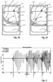
- the acoustic wave in the open roof assembly may be detected almost instantaneously and, as a consequence, the first contact between foreign object and open roof assembly may be detected virtually instantaneously, i.e. within a few microseconds. This is shown in Figs. 2A - 2F in more detail.
- FIGs. 2A an embodiment of an open roof assembly 1 according to the present invention is illustrated with the roof opening 3a, the moveable panel 2a and the fixed panel 2b.
- the moveable panel 2a is moving in a direction A.
- Four accelerometers 12-1, 12-2, 12-3 and 12-4 are arranged on the moveable panel 2a, one in every corner of the moveable panel 2a.
- a foreign object 20, which may be a human finger or any other kind of object, is positioned in the path of movement of the moveable panel 2a.
- Fig. 2A illustrates a situation just before the moveable panel 2a will collide with the foreign object 20.
- the acoustic wave 13 expands in every direction and a wave front eventually arrives at time t1 at the second accelerometer 12-2 as shown in Fig. 2C . So, at time t1, the second accelerometer 12-2 detects the acoustic wave 13, while the other accelerometers 12-1, 12-3 and 12-4 do not yet detect the acoustic wave 13.
- Fig. 2D the acoustic wave 13 arrives at the first accelerometer 12-1 at time t2.
- time t3 the wave front of the acoustic wave 13 reaches the fourth accelerometer 12-4.
- Fig. 2F shows the arrival of the wave front of acoustic wave 13 at the third accelerometer 12-3 at time t4.
- the acoustic wave 13 thus has a circular wave front that moves with a substantially constant velocity.
- the actual velocity depends on the material properties of the moveable panel 2a. Through experimentation with a glass panel of an actual open roof assembly, it was found that the velocity of the acoustic wave 13 may be in the order of about 2 meter per millisecond or even higher. Considering that the moveable panel 2a commonly is smaller than 1 m in width and length, it appears that the time elapsed between t0 and t4 may be expected to be shorter than 0.5 milliseconds.
- the velocity of the acoustic wave is lower in another embodiment, it may still be expected that the collision may be detected within a few milliseconds from mechanical contact with an edge of the moveable panel 2a and a movement of the moveable panel 2a may be stopped or its direction may be reversed.
- Fig. 3 shows a graph in which actual wave signals of four accelerometers are plotted against time.
- the legend of the graph of Fig. 4 indicates four sensors, i.e. accelerometers: sensor 1, sensor 2, sensor 3 and sensor 4.
- sensors i.e. accelerometers: sensor 1, sensor 2, sensor 3 and sensor 4.
- these sensors were arranged on a moveable panel 2a corresponding to the accelerometers 12-1 - 12-4, as shown in Figs. 2A - 2F , and the illustrated wave signals were recorded. It is noted that the location of impact corresponding to these four wave signals does not correspond to the location of impact as illustrated in Fig. 2A - 2F .
- sensor 3 starts to detect an acoustic wave generated due to a collision between a foreign object and the moveable panel.
- sensor 4 starts to detect the acoustic wave corresponding to the same collision.
- sensor 2 starts to detect the same acoustic wave and, at time t4, sensor 1 starts to detect the same acoustic wave.
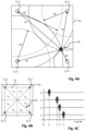
- Fig. 4A shows the moveable panel 2a with first accelerometer 12-1, second accelerometer 12-2, third accelerometer 12-3 and fourth accelerometer 12-4.
- a foreign object has contacted/collided with the moveable panel 2a at an impact location 20 at time t0.
- the impact location 20 is closest to the fourth accelerometer 12-4 at a fourth distance d4, followed by the second accelerometer 12-2 at a second distance d2, the third accelerometer 12-3 at a third distance d3 and the first accelerometer 12-1 at a first distance d1.
- the acoustic wave generated by the mechanical impact on the impact location 20 at time t0 is detected by the respective accelerometers 12-1 - 12-4.
- the fourth accelerometer 12-4 detects the acoustic wave at time t1; the second accelerometer 12-2 detects the acoustic wave at time t2; the third accelerometer 12-3 detects the acoustic wave at time t3; and the first accelerometer 12-1 detects the acoustic wave at time t4.
- the timing of the receipt of the acoustic wave at the respective accelerometers 12-1 - 12-4 is schematically illustrated in Fig.
- FIG. 4A With known distances d1 - d4, it is enabled to identify the impact location 20. For example, as shown in Fig. 4A , drawing a circle (dashed lines) around each accelerometer 12-1 - 12-4 at the respective distances d1 - d4 provides a single point where all four circles meet, which is the impact location 20. Many mathematical methods are known to find such an intersection of circles. Further, the same intersection is identifiable by use of three circles and, hence, a system with three suitably arranged accelerometers would suffice to identify the impact location 20, at least theoretically.
- time t0 of impact is a priori unknown. Consequently, a time lapse between t0 and t1 is unknown and the distance d4 is unknown.
- the timing differences may be used.
- time t1 may be used as a reference timing. With t1 as a reference timing, the time lapse t0 - t1 is ignored, initially. Accordingly, the fourth distance d4 is ignored, initially.
- a radius of each of these three dash-dotted circles may be increased with a same value. Increasing the radius of each dash-dotted circles eventually leads to the dashed circles, intersecting at a single location. There is only one value for which these circles intersect at a single location. This value is the fourth distance d4 and said single location is the impact location 20. It is noted that this approach may as well be performed starting with an assumption of d4' - 0 such that a combination with just two of the other distances d1', d2' and d3' allows to find an intersection location of three circles.
- Fig. 4B shows a simple and computationally effective embodiment of a method to derive the impact location.
- This embodiment of the method initially focuses on the order of the arrival of the acoustic wave at the respective accelerometers. Based on at which accelerometer the acoustic wave arrives first and where it arrives second, the impact location is within one of eight predetermined sectors s ij , which are indicated by the dashed lines and wherein the index i indicates the first accelerometer detecting the acoustic wave and the index j indicates the second accelerometer detecting the acoustic wave.
- the resulting acoustic wave arrives first at the fourth accelerometer 12-4 and arrives second at the second accelerometer 12-2 (see also Fig. 4C ). Knowing that the acoustic wave has first arrived at the fourth accelerometer 12-4, implies that the impact location 20 is within one of the two sectors s42, s43, since in those two sectors s42, s43 the fourth accelerometer 12-4 is closest. From the impact location 20, the second accelerometer 12-2 is closer than the third accelerometer 12-3 and with the second accelerometer 12-2 detecting the acoustic wave before the third accelerometer 12-3, it is derived that the impact location 20 is within the sector s42.
- This simple assessment of the first two accelerometers to detect the acoustic wave provides already important information on the impact location. For example, it may be relevant with respect to safety to know whether a collision occurred on the front edge ( Fig. 1B : FE), the rear edge (RE) or one of the side edges (SE). This is easily derived.
- the velocity of the wave front of the acoustic wave may be taken into account.
- an impact within a centre section 14 of the moveable panel 2a i.e. a part sufficiently distanced from an edge of the moveable panel 2a, may not be relevant with respect to entrapment, since a foreign object cannot get trapped at such location.
- the illustrated centre section 14 is defined by the locations of the four accelerometers 12-1 - 12-4. However, a location and dimensions of the centre section 14 may be freely selected depending on requirements, specifications and desired functionality, as apparent to those skilled in the art.
- an estimated impact location may be derived from a ratio of the time differences between the arrivals of the acoustic wave at the respective accelerometers 12-1 - 12-4. For example, in an embodiment, based on a known velocity of the acoustic wave front, the time differences may be transformed to normalized coefficients. Thereto, the time differences may be divided by a time period needed for an acoustic wave front to propagate from the first accelerometer 12-1 to the fourth accelerometer 12-4.
- c1 t2 ⁇ t1 / T14
- c2 t3 ⁇ t1 / T14
- c3 t4 ⁇ t1 / T14
- c1 a first coefficient
- c2 a second coefficient
- c3 a third coefficient
- T14 is the time needed for an acoustic wave front to propagate from the location of the first accelerometer 12-1 to the location of the fourth accelerometer 12-4.
- Each location of the moveable panel 2a has a unique combination of these coefficients.
- the impact location may be simply derived from the lookup table.
- the look-up operation may be accelerated by creating multiple smaller look-up tables.
- each sector s ij may have a dedicated look-up table.
- the first two accelerometers detecting the acoustic wave determine which look-up table is used to determine a more detailed and more accurate position on the impact location 20.
- a coarseness (preciseness) of the impact location determination may be selected by the size of the look-up table.
- the position of the impact location 20 may be derived to be within an area of a certain size, for example an area of 2 cm by 2 cm.
- the position of the impact location may be derived with higher precision by interpolation. Interpolating is presumed to lie within the ambit of the skilled person and is therefore not further elucidated herein. It is however noted that, due to ignoring the initial time lapse between impact and first detection (t1 - t0), the spread of coefficients is nonlinear.
- the interpolation may be a relatively complex, nonlinear interpolation for achieving high-accuracy or may be a relatively simple linear interpolation for reducing computational load, for example.
- a look-up table may store every combination of coefficients that correspond to a position within the centre section 14. Consequently, if a combination of coefficients is not present in the look-up table, the impact location 20 is outside the centre section 14 and is therefore relatively close to an edge of the moveable panel 2a.
- Such impacts may be treated as a potential entrapment, while impacts in the centre section 14 may be treated differently in accordance with the present invention.
- a potential entrapment situation may be detected by mere consideration of the coefficients and deciding that a potential entrapment has occurred if one or more of the coefficients exceed a predetermined threshold. Combinations of coefficients could be considered as well, of course.
- the accelerometers are presented as attached to the moveable panel 2a and, in particular, one accelerometer in each corner of the moveable panel 2a.
- the present invention is however not limited to such particular embodiment.
- the accelerometers for use in the present invention may be located at virtually any position on any assembly part that may be subject to acoustic waves, wherein the acoustic wave may be generated in such assembly part or may be received from a connected assembly part.
- Fig. 5 illustrates how the impact sensitivity of the open roof assembly 1 may be employed as a user interface.
- a first touch area 15a, a second touch area 15b and a third touch area 15c are defined on the closure member. These areas 15a - 15c are not necessarily physically different from the remainder of the closure member 2a. Still, an indication of the specific areas may be provided to a user. For example, a locally different colour may be applied or the touch areas 15a - 15c may be marked on the surface using paint or an adhesive label.
- using special lighting effects the touch areas 15a - 15c may be lighted, for example when an object, e.g. a finger, approaches one of the touch areas 15a - 15c. For example, an image representing the associated function may be projected on the touch areas 15a - 15c. Other lighting effects may be used as well, as apparent to those in the art.
- the detection system is configured to provide an operating signal when an impact in one of these areas 15a - 15c is detected, wherein the operating signal corresponds to the respective area 15a - 15c that has been touched. For example, if a user touches the first touch area 15a, the closure member 2a may slide open; if the user touches the second touch area 15b, the closure member 2a may move into the tilt position and if the user touches the third touch area 15c, a rollo blind (not shown) may close. As the closure member 2a may not be accessible when it is in the open position, it may not be sensible to provide for a similar touch area for closing the closure member 2a.
- ticking against an edge at the front end FE of the closure member 2a may be defined as an operating command to close the closure member 2a.
- the command may be more reliable if it were defined as a double impact, e.g. a double ticking at said edge.
- any other sequence of impacts may be defined.
- the touch areas may also be sensitive to certain impact sequences.
- the commands may include commands for operating the closure member 2a, a rollo blind, lighting, and the like. Potentially, the operating commands are not limited to commands relating to the open roof assembly. Essentially, any command relating to a function of a vehicle may be defined, provided that the detection system is operatively connected to the components performing such function.
- Fig. 6 shows an embodiment, wherein an optical detection technique is used in the detection system.
- three infrared beam transmitters 16a - 16c have been provided on a first side of the roof opening 3a and three corresponding infrared receivers 17a - 17c, respectively, have been provided on a second, opposing side of the roof opening 3a.
- Each transmitter 16a - 16c emits a respective infrared beam 18a - 18c.
- the infrared beams 18a- 18c are emitted continuously and are continuously detected by the receivers 17a - 17c to confirm that no blocking foreign object is present.
- a foreign object 20 is present between a third transmitter 16c and a third receiver 17c such that a third infrared beam 18c is blocked.
- the third receiver 17c does not receive any infrared radiation.
- the detection system thus detects that the foreign object 20, blocking the infrared radiation, is present.
- the foreign object 20 may be a finger of a user.
- the user may move his or her finger through the infrared beams 18a - 18c, e.g. in a forward direction.
- the finger first blocks a first infrared beam 18a, then blocks a second infrared beam 18b and then the third infrared beam 18c.
- a trajectory of the finger movement may be detected.
- the finger movement i.e. a gesture
- the detection system interprets such a gesture and provides an operating signal to e.g. a control unit that executes a corresponding function.
- the embodiment of substantially parallel infrared beams may be sensitive to disturbances and erroneous detections. For example, if one of the receivers is covered with dust or dirt, the closure member 2a cannot close anymore due to the fact that an obstructing foreign object is continuously detected.
- Fig. 7A illustrates an embodiment for reducing sensitivity to disturbances and errors.
- the third infrared beam 18c is illustrated to have a wide angle such that each of the receivers 17a - 17c detects a part of the third infrared beam 18c.
- a same wide-angle infrared beam may be emitted by the first and second transmitters 16a, 16b, thus providing a denser detection field.
- the detection system becomes more reliable.
- Fig. 7B illustrates a further embodiment, wherein a detailed self-diagnosis is enabled.
- the embodiment of Fig. 7B like the embodiment of Fig. 7A , uses transmitters 16a - 16c with respective wide-angled beams 18a - 18c.
- the radiation emitted by the transmitters 16a - 16c have been modulated with a predetermined modulation pattern, which may be used as a transmitter identifying signal.
- the term ⁇ modulation' and ⁇ modulation pattern' are intended to be construed broadly. Any temporal variation in the radiation beam may be regarded a modulation. Such temporal variation is advantageously used to enable to ignore any radiation from any other source, like infrared radiation originating from the sun, for example.
- the modulation of each of the transmitters 16a - 16c is different. Consequently, the three differently modulated radiation beams will be detected by each receiver 17a - 17c.
- the receivers 17a - 17c will detect radiation having a modulation that is a combination of the three modulated radiation beams 18a - 18c. With a suitable selection of modulation patterns, the combined modulation may be traced back and the separate contributions from the three transmitters 16a - 16c may be derived.
- a receiver output signal may be supplied to suitable electronic circuitry that is configured to perform such operation.
- suitable filters may be used to separate the three contributions using the predetermined modulation patterns.
- the receiver output signal is supplied to a processing unit that mathematically separates the three contributions. For example, if the modulation patterns are differentiated by frequency, a Fourier transformation may provide the desired contributions.
- a person skilled in the art of signal design and signal processing is presumed to be able to select suitable modulation patterns and corresponding circuitry and/or techniques to separate such modulation patterns from the receiver outputs. Therefore, these features and components are not further elucidated herein.
- a foreign object 20 is present in the field of detection (and at least one property, like its location or its velocity) or a transmitter is inoperable or a receiver is inoperable.
- a certain part of the radiation beams is blocked.
- the second and the third receiver 18b, 18c do not receive radiation from the second transmitter 16b and the first and the second receivers 18a, 18b do not receive radiation from the second and the third transmitters 16b, 16c.
- a diagnosis routine may be part of a start-up sequence, for example, wherein the inputs and outputs of the transmitters 16a - 16c and the receivers 17a - 17c is tested and evaluated before the closure member 2a is operated at all.
- the self-diagnosis capability may be further improved by positioning both transmitters and receivers on each side of the roof opening 3a.
- the radiation detected by the receivers at one side of the roof opening may be expected to have a certain correspondence to the radiation detected by the receivers at the opposing side, otherwise a potential error may be assumed.
- Fig. 8A illustrates a further embodiment, wherein a CCD-array receiver 17d is provided. Hence, a wide receiver field is provided removing gaps in the field of detection at the receiver side of the roof opening 3a.
- two transmitters 16a, 16b and 16c, 16d are positioned on opposing sides of the roof opening 3a. Between each of the pairs of transmitters 16a, 16b and 16c, 16d a CCD-array receiver 17d, 17e, respectively, are provided. Thus, a virtually complete coverage of the roof opening 3a is provided.
- Fig. 9 illustrates an embodiment having four transmitters 16a - 16d and four receivers 17a - 17d.
- the object 20 is shown multiple times corresponding to positions of the object 20 with a short time lapse between each.
- the object 20 is thus moved in a forward direction along a trajectory 21 and thus starts with blocking the radiation beam emitted by the first transmitter 16a and received by the first receiver 17a and from there moving towards a front F of the open roof assembly 1.
- the trajectory 21 is detectable by tracing the object 20 over time. Upon detection of such a trajectory, the detection system establishes that a user command is detected and an operating signal is provided to a control unit in order to execute such command.
- Figs. 10A and 10B show a vehicle roof 1 provided with an open roof assembly with a first moveable panel 2a and a second fixed panel 2b. Between the moveable panel 2a and the fixed panel 2b, an optional middle beam 2c is shown.
- a first optical detection system 30 and a second optical detection system 32 are provided.
- Each of the optical detection systems 30, 32 may be common digital cameras, for example, or may be any other suitable optical detection system, e.g. an infrared imaging system.
- the optical detector systems 30, 32 image a predetermined field of view.
- the field of view of the first optical detection system 30 and the second optical detection system 32 is shown as FOV-borders 30a, 30b and 32a, 32b, respectively.
- the first optical detection system 30 is arranged in front of (as seen in a normal driving direction of the vehicle) the open roof assembly and close to a lower surface of the moveable panel 2a.
- the first optical detection system 30 images an area directly below the moveable panel 2a such to enable to detect an object like a finger providing an operating command.
- the field of view extends through the opening in the vehicle roof 1 such to enable to detect an object 20 in the opening.
- the open roof assembly may distinguish between a potential entrapment of the detected object or an operating command of such object in accordance with the present invention.
- the second optical detection system 32 is arranged in a rear area close to a lower surface of the fixed panel 2b.
- a sunshade holder 24 is arranged in the rear area as well and is configured to hold a flexible web 22 that may be moved to extend below the moveable panel 2a and the fixed panel 2b to protect the interior of the vehicle against excessive sunlight, for example.
- the second optical detection system 32 may not be required for prevention of an entrapment by the moveable panel 2a and as such it is noted that the second optical detection system 32 is optional.
- the second optical detection system 32 may be provided for enabling to provide an operating command near the fixed panel 2b as well as near the opening of the moveable panel 2a. Further, the second detection system 32 may be used to prevent a collision between an object and a leading edge of the sunshade web 22, for example.
- the first and second optical detection systems 30, 32 are both shown schematically. In a practical embodiment, they may comprise an optical detector and further optical elements like lenses. Further, they may be provided with an automatic focus system, where appropriate.
- the images received from the optical detection systems 30, 32 may be processed by suitable image processing software running on a generic image processing unit or by a dedicated image processing unit.
- the image processing may include stitching the images recorded by the two separate detection systems 30, 32, for example. It is noted that a camera system for detecting objects, object movements and predetermined gestures are known in the prior art. Therefore, a detailed description of such a processing system is omitted herein.
- Fig. 11A shows a top view of another embodiment wherein two optical detection systems 30, 32 have been arranged at opposing corners of the open roof assembly.
- the field of view of each detection system 30, 32 have been arranged differently.
- an effective field of view 30c of the first optical detection system 30 is dotted.
- the fields of view of the two detection systems 30, 32 together cover the area of the moveable panel 2a and the fixed panel 2b.
- a finger 20 may move through the field of view 32c of the second detection system 32 parallel to the middle beam 2c and thus into the field of view 30c of the first detection system 30.
- the processing system (not shown) is configured to detect and process the whole movement despite the transition from one of the fields of view 32c to the other field of view 30c.
- the fields of view of both optical detection systems 30, 32 overlap significantly.
- an object 20 may be arranged in both fields of view.
- Such large overlap may ease image processing for an object moving from one field of view to the other.
- an optical detection system for detecting objects and gestures are as such known from the prior art and further details of possible embodiments are omitted herein.
- the detection system according to the present invention has a function of preventing entrapment of a foreign object.
- the detection system may be an additional entrapment detection system next to another detection system.
- the detection system according to the present invention has a function of providing a user interface.
- This user interface functionality may be additional to another user interface, like switches or a user interface application running on a portable computer device, e.g. smartphone, having a touch-sensitive panel, possibly connected over the Internet or over a local connection using a local communication protocol like Bluetooth.
- a portable computer device e.g. smartphone
- a touch-sensitive panel possibly connected over the Internet or over a local connection using a local communication protocol like Bluetooth.
- structural elements may be generated by application of three-dimensional (3D) printing techniques. Therefore, any reference to a structural element is intended to encompass any computer executable instructions that instruct a computer to generate such a structural element by three-dimensional printing techniques or similar computer controlled manufacturing techniques. Furthermore, any such reference to a structural element is also intended to encompass a computer readable medium carrying such computer executable instructions.
- the terms and phrases used herein are not intended to be limiting, but rather to provide an understandable description of the invention.
- the terms "a” or “an”, as used herein, are defined as one or more than one.
- the term plurality, as used herein, is defined as two or more than two.
- the term another, as used herein, is defined as at least a second or more.
- the terms including and/or having, as used herein, are defined as comprising (i.e., open language).
- the term coupled, as used herein, is defined as connected, although not necessarily directly.
Landscapes
- Engineering & Computer Science (AREA)
- Mechanical Engineering (AREA)
- Power-Operated Mechanisms For Wings (AREA)
- Geophysics And Detection Of Objects (AREA)
Claims (14)
- Ensemble de toit ouvrant pour fournir une ouverture de toit pouvant être fermée (3a) dans un toit de véhicule (1), l'ensemble de toit ouvrant comprenant un élément de fermeture (2a) qui est agencé de manière mobile pour ouvrir et fermer l'ouverture de toit et un système de détection pour détecter un objet (20) dans l'ouverture de toit, dans lequel le système de détection est configuré pour déterminer au moins une propriété de l'objet ;sélectionner un signal à partir d'un groupe de signaux en fonction de l'au moins une propriété déterminée de l'objet, le groupe de signaux comprenant au moins un signal de piégeage et un signal de fonctionnement, dans lequelle signal de piégeage est sélectionné lorsqu'un piégeage potentiel est détecté ; etle signal de fonctionnement est sélectionné lorsqu'aucun piégeage potentiel n'est détecté et que le signal de fonctionnement est associé à un(e) événement ou action détecté(e) de l'objet comme prédéfini ;
etfournir le signal sélectionné. - Ensemble de toit ouvrant selon la revendication 1, dans lequel le signal de piégeage est sélectionné et fourni lorsqu'un objet détecté empêche l'élément de fermeture de se déplacer vers une position prédéterminée.
- Ensemble de toit ouvrant selon la revendication 1, dans lequel le signal de fonctionnement est sélectionné et fourni lorsque l'objet détecté réalise une action prédéfinie.
- Ensemble de toit ouvrant selon la revendication 1, dans lequel le système de détection comprend un système de détection et de localisation d'impact mécanique, le système de détection et de localisation d'impact mécanique étant configuré pour détecter un impact mécanique et pour localiser l'impact mécanique, et dans lequel :le signal de piégeage est fourni lorsqu'un impact mécanique est détecté dans une section de bord du panneau mobile ; etle signal de fonctionnement est fourni lorsqu'un impact mécanique est détecté dans une section centrale du panneau mobile.
- Ensemble de toit ouvrant selon la revendication 1, dans lequel le système de détection comprend un système de détection optique pour détecter un objet dans une ouverture, dans lequel le système de détection optique comprend un émetteur optique (16a) pour transmettre un faisceau lumineux (18a) et un récepteur optique (17a) pour détecter le faisceau lumineux.
- Ensemble de toit ouvrant selon la revendication 5, dans lequel le système de détection comprend un certain nombre d'émetteurs et un certain nombre de récepteurs, dans lequel un faisceau de rayonnement d'un émetteur est dirigé au niveau de chacun du certain nombre des récepteurs.
- Ensemble de toit ouvrant selon la revendication 6, dans lequel le faisceau de rayonnement provenant de chacun du certain nombre d'émetteurs est modulé, dans lequel la modulation du faisceau de rayonnement provenant d'un émetteur diffère de la modulation du faisceau de rayonnement provenant des autres émetteurs.
- Ensemble de toit ouvrant selon la revendication 7, dans lequel chaque récepteur est couplé de manière fonctionnelle à une unité de commande pour amener un signal de rayonnement reçu, dans lequel le signal de rayonnement reçu représente une quantité de rayonnement reçue au niveau du récepteur, et dans lequel l'unité de commande est configurée pour déduire du signal de rayonnement reçu de quel émetteur le rayonnement provient.
- Ensemble de toit ouvrant selon la revendication 8, dans lequel l'unité de commande est configurée pour déduire une trajectoire d'objet (21) d'un objet se déplaçant à travers les faisceaux de rayonnement provenant du certain nombre d'émetteurs et dans lequel un du signal de piégeage et du signal de fonctionnement est fourni sur la base de la trajectoire d'objet.
- Véhicule comprenant l'ensemble de toit ouvrant selon la revendication 1.
- Procédé de fonctionnement d'un ensemble de toit ouvrant, l'ensemble de toit ouvrant étant configuré pour fournir une ouverture de toit pouvant être fermée (3a) dans un toit de véhicule (1), l'ensemble de toit ouvrant comprenant un élément de fermeture (2a) qui est agencé de manière mobile pour ouvrir et fermer l'ouverture de toit, le procédé comprenant les étapes suivantes :la détection d'un objet (20) dans l'ouverture de toit ;la détermination d'au moins une propriété de l'objet la sélection d'un signal à partir d'un groupe de signaux, le groupe comprenant au moins un signal de piégeage et un signal de fonctionnement, en fonction de l'au moins une propriété déterminée de l'objet, dans lequelle signal de piégeage est sélectionné lorsqu'un piégeage potentiel est détecté ; etle signal de fonctionnement est sélectionné lorsqu'aucun piégeage potentiel n'est détecté et le signal de fonctionnement est associé à un événement ou une action détecté(e) de l'objet comme prédéfini ;
etla fourniture d'un signal de piégeage ou d'un signal de fonctionnement en fonction de l'objet détecté. - Procédé selon la revendication 11, dans lequel le procédé comprend :la détection de l'objet sur la base d'un impact mécanique sur l'ensemble de toit ouvrant ;la détection d'un emplacement d'impact ; etla sélection du signal de piégeage ou du signal de fonctionnement en fonction de l'emplacement détecté de l'impact.
- Procédé selon la revendication 11, dans lequel le procédé comprend :la détection de l'objet sur la base d'un faisceau de rayonnement bloqué ;la détection d'une position de l'objet dans un champ de détection, dans lequel le champ de détection comprend un certain nombre de faisceaux de rayonnement ; etla sélection du signal de piégeage ou du signal de fonctionnement en fonction de la position de l'objet dans le temps.
- Produit-programme d'ordinateur comprenant des instructions lisibles par ordinateur pour donner l'instruction à une unité de commande de mettre en œuvre le procédé selon la revendication 11.
Applications Claiming Priority (2)
| Application Number | Priority Date | Filing Date | Title |
|---|---|---|---|
| EP18209611 | 2018-11-30 | ||
| EP18209592.7A EP3659839A1 (fr) | 2018-11-30 | 2018-11-30 | Système anti-pincement pour un ensemble de toit ouvrant |
Publications (2)
| Publication Number | Publication Date |
|---|---|
| EP3659840A1 EP3659840A1 (fr) | 2020-06-03 |
| EP3659840B1 true EP3659840B1 (fr) | 2024-11-06 |
Family
ID=68699271
Family Applications (1)
| Application Number | Title | Priority Date | Filing Date |
|---|---|---|---|
| EP19211721.6A Active EP3659840B1 (fr) | 2018-11-30 | 2019-11-27 | Système anti-pincement pour un ensemble de toit ouvrant |
Country Status (3)
| Country | Link |
|---|---|
| US (1) | US11686141B2 (fr) |
| EP (1) | EP3659840B1 (fr) |
| CN (1) | CN111251847B (fr) |
Families Citing this family (2)
| Publication number | Priority date | Publication date | Assignee | Title |
|---|---|---|---|---|
| EP4043681B1 (fr) * | 2021-02-11 | 2025-04-09 | Inalfa Roof Systems Group B.V. | Système de détection de pincement |
| CN113565392B (zh) * | 2021-07-29 | 2023-03-28 | 中国第一汽车股份有限公司 | 车辆空气流通的控制方法、装置、计算机设备和存储介质 |
Citations (1)
| Publication number | Priority date | Publication date | Assignee | Title |
|---|---|---|---|---|
| EP2270301B1 (fr) * | 2009-06-29 | 2014-10-22 | Yachiyo Industry Co., Ltd. | Système de toit ouvrant avec une sécurité antipincement incluant un panneau de toit ouvrant et un panneau de pare-soleil |
Family Cites Families (28)
| Publication number | Priority date | Publication date | Assignee | Title |
|---|---|---|---|---|
| JPS5830830A (ja) * | 1981-08-13 | 1983-02-23 | Aisin Seiki Co Ltd | サンル−フ用駆動装置 |
| JPH0359280A (ja) * | 1989-07-27 | 1991-03-14 | Aisin Seiki Co Ltd | 開口覆材の自動開閉装置 |
| US6701673B1 (en) | 1992-05-13 | 2004-03-09 | Brose Fahrzeugteile Gmbh & Co. Kg | Openable and closable motor vehicle window |
| US5955854A (en) * | 1992-09-29 | 1999-09-21 | Prospects Corporation | Power driven venting of a vehicle |
| DE19833811C2 (de) * | 1998-07-28 | 2001-10-04 | Webasto Vehicle Sys Int Gmbh | Öffnungsfähiges Fahrzeugdach mit Einklemmschutz |
| CA2398943A1 (fr) * | 2000-01-31 | 2001-08-02 | Prospects, Corp. | Verrouillage de securite pour dispositif de fermeture mecanique |
| US20020039008A1 (en) * | 2000-09-29 | 2002-04-04 | Siemens Automotive Corporation | Power closure sensor system and method |
| DE602004018459D1 (de) * | 2004-04-26 | 2009-01-29 | Inalfa Roof Sys Group Bv | Öffnungsfähige Dachkonstruktion für ein Fahrzeug |
| FR2871581B1 (fr) * | 2004-06-15 | 2006-09-08 | Arvinmeritor Light Vehicle Sys | Systeme de detection d'un obstacle et procede de detection d'un obstacle |
| US7521665B2 (en) * | 2006-07-07 | 2009-04-21 | Leoni Ag | Sensor system, sensor element, and method with a light sensor and an electrical sensor for monitoring a closing mechanism |
| DE202006013335U1 (de) * | 2006-08-30 | 2008-01-03 | Brose Fahrzeugteile Gmbh & Co. Kommanditgesellschaft, Coburg | Einklemmschutzvorrichtung |
| US7436136B2 (en) * | 2006-09-26 | 2008-10-14 | Arvinmeritor Light Vehicle Systems - France | Camera based anti-pinch system |
| DE102008025247B4 (de) * | 2007-05-28 | 2018-05-24 | Asmo Co., Ltd. | Steuervorrichtung für eine Schließtafel |
| JP5285250B2 (ja) * | 2007-08-21 | 2013-09-11 | 八千代工業株式会社 | 車両のサンルーフ装置における安全装置 |
| DE102007045420B3 (de) | 2007-09-21 | 2009-02-12 | Geze Gmbh | Sicherheitssystem für einen beweglichen Flügel |
| FR2945067B1 (fr) | 2009-02-23 | 2015-02-27 | Dav | Dispositif de commande d'un ouvrant |
| US8720279B2 (en) * | 2009-05-18 | 2014-05-13 | Freescale Semiconductor, Inc. | Object detection device with variable sensitivity electric field measurement circuit |
| US20120125078A1 (en) * | 2010-11-22 | 2012-05-24 | Webasto Roof Systems Inc. | Sonic wave pinch detection system and method for a movable panel |
| US8615927B2 (en) * | 2011-11-23 | 2013-12-31 | GM Global Technology Operations LLC | Noncontact obstacle detection system using RFID technology |
| WO2013116940A1 (fr) * | 2012-02-06 | 2013-08-15 | Taylor Kevin John | Cadre de capteur tactile sectionnel pour l'adaptation d'un écran non tactile |
| US9278610B2 (en) * | 2014-06-13 | 2016-03-08 | Ford Global Technologies, Llc | Vehicle anti-pinch moonroof control system and method |
| JP5819500B1 (ja) * | 2014-09-11 | 2015-11-24 | 株式会社城南製作所 | 車両用ドアガラス昇降装置 |
| JP6424074B2 (ja) * | 2014-11-21 | 2018-11-14 | 西川ゴム工業株式会社 | センサー付きプロテクター |
| JP5813894B1 (ja) * | 2015-03-16 | 2015-11-17 | 株式会社城南製作所 | 車両用窓ガラス昇降装置、車両用ドア、および車両 |
| US9797178B2 (en) * | 2015-07-29 | 2017-10-24 | Ford Global Technologies, Llc | Seal based object detection for vehicle door assist system |
| JP6430911B2 (ja) * | 2015-09-03 | 2018-11-28 | 株式会社東海理化電機製作所 | 開閉体制御装置 |
| JP6423778B2 (ja) * | 2015-11-13 | 2018-11-14 | 株式会社ミツバ | 開閉体駆動装置、車両用ドア、及び車両 |
| CN110325702B (zh) * | 2017-03-02 | 2021-05-04 | 株式会社电装 | 开闭体驱动装置 |
-
2019
- 2019-11-22 CN CN201911151893.9A patent/CN111251847B/zh active Active
- 2019-11-27 EP EP19211721.6A patent/EP3659840B1/fr active Active
- 2019-11-27 US US16/698,185 patent/US11686141B2/en active Active
Patent Citations (1)
| Publication number | Priority date | Publication date | Assignee | Title |
|---|---|---|---|---|
| EP2270301B1 (fr) * | 2009-06-29 | 2014-10-22 | Yachiyo Industry Co., Ltd. | Système de toit ouvrant avec une sécurité antipincement incluant un panneau de toit ouvrant et un panneau de pare-soleil |
Also Published As
| Publication number | Publication date |
|---|---|
| US11686141B2 (en) | 2023-06-27 |
| EP3659840A1 (fr) | 2020-06-03 |
| CN111251847B (zh) | 2024-09-20 |
| US20200173219A1 (en) | 2020-06-04 |
| CN111251847A (zh) | 2020-06-09 |
Similar Documents
| Publication | Publication Date | Title |
|---|---|---|
| KR101367593B1 (ko) | 쌍방향 조작 장치 및 쌍방향 조작 장치의 작동 방법 | |
| EP3105160B1 (fr) | Interface de commande d'ascenseur | |
| US20140195096A1 (en) | Apparatus and method for contactlessly detecting objects and/or persons and gestures and/or operating procedures made and/or carried out thereby | |
| US20120068956A1 (en) | Finger-pointing, gesture based human-machine interface for vehicles | |
| US11236539B2 (en) | Door trim assembly | |
| US20160132126A1 (en) | System for information transmission in a motor vehicle | |
| CN108790738B (zh) | 用于车辆的隐私系统和方法 | |
| KR20180015206A (ko) | 이동 수단의 부품의 전동식 조절을 위한 스위치의 조작 전에 사용자를 지원하기 위한 장치 및 방법 | |
| US20130204457A1 (en) | Interacting with vehicle controls through gesture recognition | |
| EP3659840B1 (fr) | Système anti-pincement pour un ensemble de toit ouvrant | |
| KR20220024928A (ko) | 안티-핀치 검출 방법 및 시스템 | |
| KR20130068538A (ko) | 차량용 스마트 도어 | |
| US10884614B1 (en) | Actuation interface | |
| KR20170069212A (ko) | 객실의 비접촉 모니터링을 위한 센서 장치를 구비한 도어 시스템 | |
| CN102473063A (zh) | 汽车中的操纵装置的运行方法和操纵装置 | |
| JP6391000B2 (ja) | 窓開閉システム | |
| US20180094471A1 (en) | Vehicle window with gesture control | |
| CN108399044A (zh) | 用户界面、运输工具和用于区分用户的方法 | |
| KR101946746B1 (ko) | 차량에서 비-차량 오브젝트의 위치 결정 | |
| US20140168438A1 (en) | Camera module for vehicle and monitoring system provided with the same | |
| JP2021512392A (ja) | バーチャルコンテンツを表示するためのヘッドマウント式電子ディスプレイ装置の操作方法およびバーチャルコンテンツを表示するためのディスプレイシステム | |
| US10261593B2 (en) | User interface, means of movement, and methods for recognizing a user's hand | |
| US20200346580A1 (en) | System and methods for exterior vehicle display and panel exciters | |
| EP3659839A1 (fr) | Système anti-pincement pour un ensemble de toit ouvrant | |
| CN105759955B (zh) | 输入装置 |
Legal Events
| Date | Code | Title | Description |
|---|---|---|---|
| PUAI | Public reference made under article 153(3) epc to a published international application that has entered the european phase |
Free format text: ORIGINAL CODE: 0009012 |
|
| STAA | Information on the status of an ep patent application or granted ep patent |
Free format text: STATUS: THE APPLICATION HAS BEEN PUBLISHED |
|
| AK | Designated contracting states |
Kind code of ref document: A1 Designated state(s): AL AT BE BG CH CY CZ DE DK EE ES FI FR GB GR HR HU IE IS IT LI LT LU LV MC MK MT NL NO PL PT RO RS SE SI SK SM TR |
|
| AX | Request for extension of the european patent |
Extension state: BA ME |
|
| STAA | Information on the status of an ep patent application or granted ep patent |
Free format text: STATUS: REQUEST FOR EXAMINATION WAS MADE |
|
| 17P | Request for examination filed |
Effective date: 20201111 |
|
| RBV | Designated contracting states (corrected) |
Designated state(s): AL AT BE BG CH CY CZ DE DK EE ES FI FR GB GR HR HU IE IS IT LI LT LU LV MC MK MT NL NO PL PT RO RS SE SI SK SM TR |
|
| STAA | Information on the status of an ep patent application or granted ep patent |
Free format text: STATUS: EXAMINATION IS IN PROGRESS |
|
| 17Q | First examination report despatched |
Effective date: 20210414 |
|
| GRAP | Despatch of communication of intention to grant a patent |
Free format text: ORIGINAL CODE: EPIDOSNIGR1 |
|
| STAA | Information on the status of an ep patent application or granted ep patent |
Free format text: STATUS: GRANT OF PATENT IS INTENDED |
|
| INTG | Intention to grant announced |
Effective date: 20240605 |
|
| GRAS | Grant fee paid |
Free format text: ORIGINAL CODE: EPIDOSNIGR3 |
|
| GRAA | (expected) grant |
Free format text: ORIGINAL CODE: 0009210 |
|
| STAA | Information on the status of an ep patent application or granted ep patent |
Free format text: STATUS: THE PATENT HAS BEEN GRANTED |
|
| AK | Designated contracting states |
Kind code of ref document: B1 Designated state(s): AL AT BE BG CH CY CZ DE DK EE ES FI FR GB GR HR HU IE IS IT LI LT LU LV MC MK MT NL NO PL PT RO RS SE SI SK SM TR |
|
| REG | Reference to a national code |
Ref country code: GB Ref legal event code: FG4D |
|
| REG | Reference to a national code |
Ref country code: CH Ref legal event code: EP |
|
| REG | Reference to a national code |
Ref country code: DE Ref legal event code: R096 Ref document number: 602019061436 Country of ref document: DE |
|
| REG | Reference to a national code |
Ref country code: IE Ref legal event code: FG4D |
|
| REG | Reference to a national code |
Ref country code: LT Ref legal event code: MG9D |
|
| REG | Reference to a national code |
Ref country code: NL Ref legal event code: MP Effective date: 20241106 |
|
| PG25 | Lapsed in a contracting state [announced via postgrant information from national office to epo] |
Ref country code: HR Free format text: LAPSE BECAUSE OF FAILURE TO SUBMIT A TRANSLATION OF THE DESCRIPTION OR TO PAY THE FEE WITHIN THE PRESCRIBED TIME-LIMIT Effective date: 20241106 Ref country code: IS Free format text: LAPSE BECAUSE OF FAILURE TO SUBMIT A TRANSLATION OF THE DESCRIPTION OR TO PAY THE FEE WITHIN THE PRESCRIBED TIME-LIMIT Effective date: 20250306 Ref country code: PT Free format text: LAPSE BECAUSE OF FAILURE TO SUBMIT A TRANSLATION OF THE DESCRIPTION OR TO PAY THE FEE WITHIN THE PRESCRIBED TIME-LIMIT Effective date: 20250306 |
|
| PG25 | Lapsed in a contracting state [announced via postgrant information from national office to epo] |
Ref country code: NL Free format text: LAPSE BECAUSE OF FAILURE TO SUBMIT A TRANSLATION OF THE DESCRIPTION OR TO PAY THE FEE WITHIN THE PRESCRIBED TIME-LIMIT Effective date: 20241106 Ref country code: FI Free format text: LAPSE BECAUSE OF FAILURE TO SUBMIT A TRANSLATION OF THE DESCRIPTION OR TO PAY THE FEE WITHIN THE PRESCRIBED TIME-LIMIT Effective date: 20241106 |
|
| REG | Reference to a national code |
Ref country code: AT Ref legal event code: MK05 Ref document number: 1739016 Country of ref document: AT Kind code of ref document: T Effective date: 20241106 |
|
| PG25 | Lapsed in a contracting state [announced via postgrant information from national office to epo] |
Ref country code: BG Free format text: LAPSE BECAUSE OF FAILURE TO SUBMIT A TRANSLATION OF THE DESCRIPTION OR TO PAY THE FEE WITHIN THE PRESCRIBED TIME-LIMIT Effective date: 20241106 |
|
| PG25 | Lapsed in a contracting state [announced via postgrant information from national office to epo] |
Ref country code: ES Free format text: LAPSE BECAUSE OF FAILURE TO SUBMIT A TRANSLATION OF THE DESCRIPTION OR TO PAY THE FEE WITHIN THE PRESCRIBED TIME-LIMIT Effective date: 20241106 |
|
| PG25 | Lapsed in a contracting state [announced via postgrant information from national office to epo] |
Ref country code: NO Free format text: LAPSE BECAUSE OF FAILURE TO SUBMIT A TRANSLATION OF THE DESCRIPTION OR TO PAY THE FEE WITHIN THE PRESCRIBED TIME-LIMIT Effective date: 20250206 |
|
| PG25 | Lapsed in a contracting state [announced via postgrant information from national office to epo] |
Ref country code: GR Free format text: LAPSE BECAUSE OF FAILURE TO SUBMIT A TRANSLATION OF THE DESCRIPTION OR TO PAY THE FEE WITHIN THE PRESCRIBED TIME-LIMIT Effective date: 20250207 Ref country code: LV Free format text: LAPSE BECAUSE OF FAILURE TO SUBMIT A TRANSLATION OF THE DESCRIPTION OR TO PAY THE FEE WITHIN THE PRESCRIBED TIME-LIMIT Effective date: 20241106 Ref country code: AT Free format text: LAPSE BECAUSE OF FAILURE TO SUBMIT A TRANSLATION OF THE DESCRIPTION OR TO PAY THE FEE WITHIN THE PRESCRIBED TIME-LIMIT Effective date: 20241106 |
|
| PG25 | Lapsed in a contracting state [announced via postgrant information from national office to epo] |
Ref country code: PL Free format text: LAPSE BECAUSE OF FAILURE TO SUBMIT A TRANSLATION OF THE DESCRIPTION OR TO PAY THE FEE WITHIN THE PRESCRIBED TIME-LIMIT Effective date: 20241106 |
|
| PG25 | Lapsed in a contracting state [announced via postgrant information from national office to epo] |
Ref country code: RS Free format text: LAPSE BECAUSE OF FAILURE TO SUBMIT A TRANSLATION OF THE DESCRIPTION OR TO PAY THE FEE WITHIN THE PRESCRIBED TIME-LIMIT Effective date: 20250206 |
|
| REG | Reference to a national code |
Ref country code: CH Ref legal event code: PL |
|
| PG25 | Lapsed in a contracting state [announced via postgrant information from national office to epo] |
Ref country code: SM Free format text: LAPSE BECAUSE OF FAILURE TO SUBMIT A TRANSLATION OF THE DESCRIPTION OR TO PAY THE FEE WITHIN THE PRESCRIBED TIME-LIMIT Effective date: 20241106 |
|
| PG25 | Lapsed in a contracting state [announced via postgrant information from national office to epo] |
Ref country code: DK Free format text: LAPSE BECAUSE OF FAILURE TO SUBMIT A TRANSLATION OF THE DESCRIPTION OR TO PAY THE FEE WITHIN THE PRESCRIBED TIME-LIMIT Effective date: 20241106 |
|
| PG25 | Lapsed in a contracting state [announced via postgrant information from national office to epo] |
Ref country code: LU Free format text: LAPSE BECAUSE OF NON-PAYMENT OF DUE FEES Effective date: 20241127 |
|
| REG | Reference to a national code |
Ref country code: CH Ref legal event code: PL |
|
| PG25 | Lapsed in a contracting state [announced via postgrant information from national office to epo] |
Ref country code: EE Free format text: LAPSE BECAUSE OF FAILURE TO SUBMIT A TRANSLATION OF THE DESCRIPTION OR TO PAY THE FEE WITHIN THE PRESCRIBED TIME-LIMIT Effective date: 20241106 |
|
| PG25 | Lapsed in a contracting state [announced via postgrant information from national office to epo] |
Ref country code: CH Free format text: LAPSE BECAUSE OF NON-PAYMENT OF DUE FEES Effective date: 20241130 |
|
| PG25 | Lapsed in a contracting state [announced via postgrant information from national office to epo] |
Ref country code: RO Free format text: LAPSE BECAUSE OF FAILURE TO SUBMIT A TRANSLATION OF THE DESCRIPTION OR TO PAY THE FEE WITHIN THE PRESCRIBED TIME-LIMIT Effective date: 20241106 |
|
| PG25 | Lapsed in a contracting state [announced via postgrant information from national office to epo] |
Ref country code: SK Free format text: LAPSE BECAUSE OF FAILURE TO SUBMIT A TRANSLATION OF THE DESCRIPTION OR TO PAY THE FEE WITHIN THE PRESCRIBED TIME-LIMIT Effective date: 20241106 |
|
| PG25 | Lapsed in a contracting state [announced via postgrant information from national office to epo] |
Ref country code: CZ Free format text: LAPSE BECAUSE OF FAILURE TO SUBMIT A TRANSLATION OF THE DESCRIPTION OR TO PAY THE FEE WITHIN THE PRESCRIBED TIME-LIMIT Effective date: 20241106 |
|
| PG25 | Lapsed in a contracting state [announced via postgrant information from national office to epo] |
Ref country code: IT Free format text: LAPSE BECAUSE OF FAILURE TO SUBMIT A TRANSLATION OF THE DESCRIPTION OR TO PAY THE FEE WITHIN THE PRESCRIBED TIME-LIMIT Effective date: 20241106 |
|
| REG | Reference to a national code |
Ref country code: DE Ref legal event code: R097 Ref document number: 602019061436 Country of ref document: DE |
|
| REG | Reference to a national code |
Ref country code: BE Ref legal event code: MM Effective date: 20241130 |
|
| PG25 | Lapsed in a contracting state [announced via postgrant information from national office to epo] |
Ref country code: SE Free format text: LAPSE BECAUSE OF FAILURE TO SUBMIT A TRANSLATION OF THE DESCRIPTION OR TO PAY THE FEE WITHIN THE PRESCRIBED TIME-LIMIT Effective date: 20241106 |
|
| PLBE | No opposition filed within time limit |
Free format text: ORIGINAL CODE: 0009261 |
|
| STAA | Information on the status of an ep patent application or granted ep patent |
Free format text: STATUS: NO OPPOSITION FILED WITHIN TIME LIMIT |
|
| PG25 | Lapsed in a contracting state [announced via postgrant information from national office to epo] |
Ref country code: MC Free format text: LAPSE BECAUSE OF FAILURE TO SUBMIT A TRANSLATION OF THE DESCRIPTION OR TO PAY THE FEE WITHIN THE PRESCRIBED TIME-LIMIT Effective date: 20241106 |
|
| 26N | No opposition filed |
Effective date: 20250807 |
|
| PG25 | Lapsed in a contracting state [announced via postgrant information from national office to epo] |
Ref country code: BE Free format text: LAPSE BECAUSE OF NON-PAYMENT OF DUE FEES Effective date: 20241130 |
|
| PG25 | Lapsed in a contracting state [announced via postgrant information from national office to epo] |
Ref country code: IE Free format text: LAPSE BECAUSE OF NON-PAYMENT OF DUE FEES Effective date: 20241127 |
|
| GBPC | Gb: european patent ceased through non-payment of renewal fee |
Effective date: 20250206 |
|
| PGFP | Annual fee paid to national office [announced via postgrant information from national office to epo] |
Ref country code: DE Payment date: 20251128 Year of fee payment: 7 |
|
| PG25 | Lapsed in a contracting state [announced via postgrant information from national office to epo] |
Ref country code: GB Free format text: LAPSE BECAUSE OF NON-PAYMENT OF DUE FEES Effective date: 20250206 |
|
| PGFP | Annual fee paid to national office [announced via postgrant information from national office to epo] |
Ref country code: FR Payment date: 20251125 Year of fee payment: 7 |
|
| PG25 | Lapsed in a contracting state [announced via postgrant information from national office to epo] |
Ref country code: HU Free format text: LAPSE BECAUSE OF FAILURE TO SUBMIT A TRANSLATION OF THE DESCRIPTION OR TO PAY THE FEE WITHIN THE PRESCRIBED TIME-LIMIT; INVALID AB INITIO Effective date: 20191127 |
|
| PG25 | Lapsed in a contracting state [announced via postgrant information from national office to epo] |
Ref country code: CY Free format text: LAPSE BECAUSE OF FAILURE TO SUBMIT A TRANSLATION OF THE DESCRIPTION OR TO PAY THE FEE WITHIN THE PRESCRIBED TIME-LIMIT; INVALID AB INITIO Effective date: 20191127 |