EP3660260B1 - Adapteranordnung zum verbinden eines bohrwerkzeugs mit einem bohrgestänge - Google Patents
Adapteranordnung zum verbinden eines bohrwerkzeugs mit einem bohrgestänge Download PDFInfo
- Publication number
- EP3660260B1 EP3660260B1 EP19209324.3A EP19209324A EP3660260B1 EP 3660260 B1 EP3660260 B1 EP 3660260B1 EP 19209324 A EP19209324 A EP 19209324A EP 3660260 B1 EP3660260 B1 EP 3660260B1
- Authority
- EP
- European Patent Office
- Prior art keywords
- contact region
- adapter arrangement
- arrangement according
- threaded portion
- opening
- Prior art date
- Legal status (The legal status is an assumption and is not a legal conclusion. Google has not performed a legal analysis and makes no representation as to the accuracy of the status listed.)
- Active
Links
Images





Classifications
-
- E—FIXED CONSTRUCTIONS
- E21—EARTH OR ROCK DRILLING; MINING
- E21B—EARTH OR ROCK DRILLING; OBTAINING OIL, GAS, WATER, SOLUBLE OR MELTABLE MATERIALS OR A SLURRY OF MINERALS FROM WELLS
- E21B17/00—Drilling rods or pipes; Flexible drill strings; Kellies; Drill collars; Sucker rods; Cables; Casings; Tubings
- E21B17/02—Couplings; joints
- E21B17/03—Couplings; joints between drilling rod or pipe and drill motor or surface drive, e.g. between drilling rod and hammer
-
- E—FIXED CONSTRUCTIONS
- E21—EARTH OR ROCK DRILLING; MINING
- E21B—EARTH OR ROCK DRILLING; OBTAINING OIL, GAS, WATER, SOLUBLE OR MELTABLE MATERIALS OR A SLURRY OF MINERALS FROM WELLS
- E21B17/00—Drilling rods or pipes; Flexible drill strings; Kellies; Drill collars; Sucker rods; Cables; Casings; Tubings
- E21B17/02—Couplings; joints
- E21B17/04—Couplings; joints between rod or the like and bit or between rod and rod or the like
- E21B17/042—Threaded
-
- E—FIXED CONSTRUCTIONS
- E21—EARTH OR ROCK DRILLING; MINING
- E21B—EARTH OR ROCK DRILLING; OBTAINING OIL, GAS, WATER, SOLUBLE OR MELTABLE MATERIALS OR A SLURRY OF MINERALS FROM WELLS
- E21B17/00—Drilling rods or pipes; Flexible drill strings; Kellies; Drill collars; Sucker rods; Cables; Casings; Tubings
- E21B17/02—Couplings; joints
- E21B17/04—Couplings; joints between rod or the like and bit or between rod and rod or the like
- E21B17/046—Couplings; joints between rod or the like and bit or between rod and rod or the like with ribs, pins, or jaws, and complementary grooves or the like, e.g. bayonet catches
Definitions
- the invention relates to an adapter arrangement for connecting a drilling tool to a drill string, which has a first element which has a first end connectable in the drill string or the drilling tool, a first threaded section with an external thread and a non-circular cross-section.
- the first element also has a cylindrical first contact area adjoining the first thread section or at a distance from the first thread section.
- the adapter arrangement furthermore has a second element which has a second end which can be or is connected to the drilling tool or to the drill rod and a second thread section which is complementary to the first thread section and has an internal thread and a section with a non-circular cross section.
- the second element is suitable for establishing a connection with the first element, wherein the second element has a second contact area which is in the form of cylindrical recesses, adjacent to the second threaded section or arranged at a distance from the second threaded section.
- the first element and the second element can be connected to one another in such a way that the thread of the first threaded section and the thread of the second threaded section are in engagement.
- the adapter arrangement comprises a third element which is designed and can be arranged such that, in the connected state of the first and the second element, it encloses a region of the first and second element with a non-circular cross section and is in engagement with these regions, the first contact region and the second contact region are configured such that they are in engagement when the first element and the second element are connected.
- the first element and the second element each have an opening which, in the connected state of the first and the second element, form a through opening from the first end to the second end, through which a fluid can be conducted from the drill rod to the drilling tool, and wherein the first Contact area has at least one circumferential groove and a sealing element is inserted into the groove.
- the invention is characterized in that a check valve is arranged in the through opening of the first element or of the second element, which only allows the fluid to pass from the drill rod to the drilling tool.
- Drilling tools can both drill heads for making a pilot hole as well as widening tools for widening an existing through hole in the ground.
- the adapter arrangement is used in particular for directed horizontal drilling (HDD - Horizontal Directional Driling), for example in a horizontal directional drilling process.
- HDD directed horizontal drilling
- pipelines can be laid underground without having to dig a trench.
- a horizontal drilling device creates a subterranean opening in the drive and, in the retreat, widens the opening and pulls in one or more pipes at the same time. When drilling and preferably when expanding, the drilling tool is usually rotated.
- adapter assemblies for connecting drilling tools and drill rods which have a sliding sleeve which is pushed over the connection point between the drill rod and the drilling tool and through the contour of its through-opening and the contour of the outer surface of the connecting elements of the adapter assembly then the torque between transmits the fasteners.
- flushing fluid is used to generate the horizontal bore, it is passed through a rod composed of several rod sections via the connection arrangement to the drilling tool.
- the problem then arises that drilling fluid can escape, in particular when a lateral force is exerted on the linkage or on the adapter arrangement, and can in particular enter a threaded section for connecting the connecting elements and damage it.
- a horizontal drilling rig in which a high pressure pump for supplying flushing fluid to the drill pipe and a mixing device for processing the flushing liquid with a mixing unit having a mixing pump are arranged on the chassis of the horizontal drilling rig.
- a drilling rig for creating or widening an earth borehole in which the propulsion of the rod is regulated as a function of the torque for rotating the rod.
- flushing fluid can be conducted through the drill rod to the drill head.
- Further horizontal drilling rigs with a feed drive for driving a drill rod carrying a drilling tool, which is advanced in the ground while rotating with the aid of a feed drive are from the documents DE 10 2010 004 287 A1 and US 6,189,628 B1 known.
- document DE 199 01 001 A1 discloses an earth drilling rig in which a drive carriage is provided for driving a drill rod which has a corresponding connection for supplying flushing fluid.
- document US 2012/0267170 A1 and document 2017/0074051 A1 each disclose an arrangement for connecting a drilling tool to a linkage in which a low torque connection and improved strength and durability can be established.
- first contact area in engagement with the second contact area, forces transverse to the longitudinal axis of the linkage and to the longitudinal axis of the adapter can be reliably transmitted between the first and the second element, so that no or there is only a slight deflection when a lateral force acts on the adapter arrangement, so that a stable and, in connection with the sealing element, tight connection between the first element and the second element is ensured even with large forces acting on the adapter arrangement.
- first contact area and the second contact area are designed in such a way that when the first element and the second element are connected, they engage in such a way that when a force is applied transversely to the longitudinal axis of the linkage, a force transversely to the longitudinal axis between the first contact area and the second contact area is transmitted. This achieves a stable and secure connection between the first element and the second element.
- first thread section is arranged between the first contact area and a cylindrical third contact area and if the second thread section is arranged between the second contact area and a fourth contact area formed in a further cylindrical recess.
- the third contact area and the fourth contact area are then designed such that they are in engagement when the first element and the second element are connected.
- the third contact area and the fourth contact area are designed in such a way that, when the first element and the second element are connected, they engage in such a way that when a force is applied transversely to the longitudinal axis of the linkage, a force is transmitted transversely to the longitudinal axis between the third contact area and the fourth contact area.
- first contact area and the second contact area form a fit, in particular a press fit, clearance fit or transition fit.
- the third contact area and the fourth contact area can form a fit, in particular a press fit, clearance fit or transition fit. This ensures that each complementary contact areas are designed in such a way that they already rest securely against one another in the event of small transverse forces acting on the adapter arrangement and transmit corresponding transverse forces.
- the diameter of the first contact area is smaller than the diameter of the second contact area by a value in the range from 6/100 mm to 8/100 mm.
- the diameter of the third contact area can be smaller by a value in the range from 6/100 mm to 8/100 mm than the diameter of the fourth contact area. This enables reliable force transmission between the contact areas.
- the sealing element is inserted into the circumferential groove in such a way that part of the sealing element protrudes circumferentially from the groove.
- the sealing element can be compressed when the first element is connected to the second element and a particularly good sealing effect achieve.
- the sealing element By compressing the sealing element in the connected state of the first and the second element, the sealing element can be relaxed or decompressed at least in areas if, due to the force transmission between the first contact area and the second contact area, there is a gap in partial areas between the first contact area and the second contact area arises or is enlarged, so that the sealing element also seals securely in this state.
- the first contact area has at least one second circumferential groove into which a second sealing element is inserted.
- the second sealing element is preferably inserted into the circumferential groove in such a way that part of the sealing element protrudes circumferentially from the groove.
- the first and / or the second sealing element are preferably designed as an O-ring.
- one or two grooves can be provided in the third contact area, in each of which a sealing element is inserted, which is preferably elastically deformable and of which a part of the sealing element preferably protrudes circumferentially from the groove. This enables the first and second threaded sections to be sealed off on both sides in a simple and reliable manner.
- first element and the second element each have an external polygon or external polygon, preferably an external hexagon, in the area with a non-circular cross-section.
- the third element preferably has an opening that is complementary to the regions of non-round cross-section of the first element and of the second element. This opening is designed in particular as an internal polygon, internal polygon, in particular as a hexagon socket.
- the third element is designed as a sliding sleeve and, in the connected state, can preferably be connected to the first and / or second element with at least one locking screw and / or at least one locking pin, in particular at least one dowel pin or heavy duty dowel pin, the locking pin in an opening, preferably a circumferential groove, engages in the first element or in the second element.
- a rotation of the first element with respect to the third element or of the second element with respect to the third element can be made possible, in particular a rotational movement between the first and the third element or between the second and the third element in succession a torque transmission between the first element and the third element or the second element and the third element and with a play between the non-circular cross-sectional area of the first element and the third element and / or the non-circular cross-sectional area of the second element and the third element.
- NPT National Pipe Thread
- a check valve is arranged in the through opening of the first element or the second element, which allows fluid, in particular rinsing liquid, only from the drill rod to the drilling tool. This ensures that, when the first element is separated from the second element, no dirt or flushing liquid can penetrate into the drill rod connected to the respective element or into the drilling tool connected to the element.
- the non-return valve also prevents the pipeline formed by the hollow drill pipe from becoming empty by escaping flushing fluid if no flushing fluid is introduced into the rod.
- the check valve comprises a closing element, an elastically deformable element and a sealing cone, the elastically deformable element pressing the closing element against the sealing cone in the closed state of the check valve and / or if the elastically deformable element through the open state of the check valve a fluid flow flowing through the check valve is deformed in such a way that the closing element is pressed against a second cone.
- the closing element is a ball and the elastically deformable element is a spring or an elastomer block.
- the spring is in particular a spiral spring, preferably a compression spring. This enables a simple, inexpensive and secure construction of the adapter arrangement.
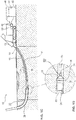
- FIG 1A a drilling rig 10 for the controlled drilling of a pilot well is shown.
- the drilling rig 10 works according to a controlled horizontal drilling process, which we also refer to as Horizontal Directional Drilling (HDD) process.
- a horizontal drilling rig available under the trade name Terra-Jet is used for this purpose.
- Such a horizontal drilling rig is for example from the document DE 101 15 233 A1 known.
- a rod 14 composed of several rod sections 13 is introduced into the ground 18 in the direction of arrow P0 with the aid of a horizontal drilling device 12 at a starting point 16 with a drill head 20 arranged on the horizontal drilling device 12 remote from the end of the rod 14.
- the horizontal drilling device 12 has a pump 42 which sucks flushing liquid 46 from a flushing liquid container 40 via a hose 48 and conveys it into the hollow rod 14 at high pressure.
- the flushing fluid 46 emerges from the drill head 20 at high pressure.
- the high pressure and the hard metal teeth of the drill head 20 cut a borehole in the ground 18.
- the drill head 20 is flattened asymmetrically at its front end and is continuously rotated with the aid of the rod 14 to produce a straight borehole. In the event of a desired lateral movement, upward movement or downward movement, the drill head 20 is stopped in a position suitable for this desired movement and is not rotated further, so that due to the asymmetrically flattened shape of the front end of the drill head 20, a corresponding deflection movement of the drill head 20 takes place in the ground 18.
- FIG. 12 is a detailed view of the end of the remote from the horizontal drilling rig 12 Linkage 14 is shown together with the drill head 20.
- An electronic probe is arranged in the drill head 20, which can be precisely located from the surface of the earth at any time with the aid of a corresponding locating device, so that the position of the drill head 20 in the earth 18 can be precisely determined at any time.
- the path of movement of the drill head 20 and thus the course of the drill channel 15 of the pilot hole is simply controlled by stopping the rotation of the drill head 20 via the rod 14 in a controlled manner, so that the control surface of the drill head 20 is brought into a position required for the desired movement. Even after the rotation of the drill head 20 has been stopped in a targeted manner, flushing fluid 46 continues to be conveyed through the rod 14 with the aid of the pump 42 and the drill head 20 is further advanced via the rod 14, so that the drilling process can be carried out with the aid of the flushing fluid 46 and the advance of the drill head 20 the desired course of the borehole is continued.
- HDPE pipes are made of high-density polyethylene, this high-density polyethylene being a thermoplastic with high density, so that the pipes made of HDPE have high toughness and rigidity, very good chemical resistance, good sliding properties, low Moisture absorption, very good processing properties, are very easy to weld and are physiologically harmless.
- tubes 26 made of other materials, in particular metal can also be drawn in.
- the horizontal drilling device 12 generates the tensile force required for the expansion process on the rod 14 and continues to guide flushing fluid 46 to the expansion head 24.
- the flushing liquid 46 at least supports the expansion of the pilot bore and also serves to drain and discharge the excess soil 18 that was loosened during the expansion process. This can take place in particular through the annular gap between the already widened area of the pilot bore, referred to as the drilling channel 15, and the drawn-in pipe 26.
- the flushing liquid 46 introduced into the annular gap also reduces the skin friction between the pipe 26 and the drilling channel 15.
- the new pipe 26 to be laid in the present case an HDPE pipe, is drawn in.
- two or more expanding tools 24 can be used one after the other with a diameter of usually up to 1000 mm.
- Pipes 26 up to a diameter of 800 mm or a pipe bundle made up of several pipes can then be drawn in.
- Water with betonite or polymers can be used as the rinsing liquid 46.
- flushing fluids 46 stabilize the drilling channel 15, reduce the friction between the drill rod 14 and the soil 18 and the friction between the pipe 26 to be pulled in and the soil 18. Furthermore, with the aid of the flushing fluid 46, soil 18 is removed from the drilling channel 15 through the pipe 26 that has already been partially pulled in promoted out.
- Figure 1D shows an enlarged section of the in Figure 1C The arrangement 10 shown.
- the end of the rod 14 remote from the horizontal drilling device 12, the expander head 24 and the pipe 26 already partially pulled into the ground 18 are shown.
- a control unit 50 of the horizontal drilling device 12 in particular a programmable logic control unit (PLC), controls the pump 42 for conveying the Rinsing fluid 46 through the linkage 14.
- PLC programmable logic control unit
- the pump 42 can be controlled by the control unit 50 in such a way that the volume flow of the flushing fluid 46 conveyed by the pump 42 and thus exiting at the drilling or expanding head 20, 24 can be controlled.
- the horizontal drilling device 12 preferably has a rotary drive for rotating the rod 14 about a longitudinal axis and the feed drive for moving the rod 14 along its longitudinal axis through the soil 18 together with the drill head 20 or expansion head 24 connected to the end of the rod 14 remote from the feed drive .
- FIG. 2 shows a perspective view of the adapter arrangement 100.
- the adapter arrangement 100 comprises a first connecting element 110, which is connected to a first rod section of the rod 14, and a second connecting element 112, which is connected to a drilling tool, such as a drilling head 20 or an expanding head 24 .
- the adapter arrangement 100 has a third connecting element 114, which can be pushed over an area with a non-cylindrical outer surface 116 of the first connecting element 110 and over an area with a non-cylindrical outer surface 118 of the second connecting element.
- the areas 116, 118 each have a hexagonal cross-section, the cross-sectional opening 120 of the third connecting element 114 having an inner cross-section that is complementary to the outer cross-sections of the areas 118, 116, so that a torque from the rod 14 to the drilling tool 20 essentially via the third connecting element 114 is transferable.
- the first connector 110 also has a section 122 with a smaller cross section than the non-cylindrical area 116, so that the third connecting element 114 can be pushed at least partially over the section 122 so that it disengages from the non-cylindrical area 118 of the second connecting element 112, to rotate this relative to the first connecting element 110.
- the third connecting element can be displaced in such a way that it at least partially encloses both non-cylindrical regions 116, 118 of the first connecting element and of the second connecting element.
- the third connecting element is also referred to as a sliding sleeve. In this state, the transmission of large torques between the rod 14 and the drilling tool 20, 24 is possible.
- the adapter arrangement 100 comprises two locking screws 124, 126, which can each be screwed through a through opening 130 in the third connecting element 114 into a hole 129 provided with an internal thread in the first connecting element 110 in order to put the third connecting element 114 in a correct position in the connected state to keep.
- a groove is also provided, into which locking pins inserted into openings 130, 131 of the third connecting element 114 engage when the elements 110, 112, 114 of the adapter arrangement 100 are connected.
- These locking pins can be provided as an alternative or in addition to the locking screws 124, 126, as will be explained in more detail below.
- the first connecting element 110 also has an area with a conical external thread 132, which can be connected to a conical internal thread in the second connecting element 112, as will be explained in more detail below.
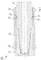
- FIG. 13 shows a sectional view of the adapter arrangement 100 according to FIG Fig. 2 in the connected state of the connecting elements 110, 112, 114.
- the external thread 132 of the first connecting element 110 is in engagement with an internal thread 134, so that a screw connection exists between the first and the second element 110, 112.
- the first connecting element 110 has a first cylindrical contact area 136 which engages with a second contact area 138 formed by a cylindrical opening in the second connecting element 112.
- first cylindrical contact area 136 there are two circumferential grooves 140, 142, in each of which a sealing element 144, 146 is arranged.
- forces acting transversely to the longitudinal axis L of the adapter arrangement 100 can be transmitted between the first connecting element 110 and the second connecting element 112 via the contact areas 136, 138.
- the first connecting element 110 comprises a third contact area 148 which engages with a further contact area 150 present in the cylindrical opening of the second connecting element 112. Forces can also be transmitted transversely to the longitudinal axis of the adapter arrangement 100 via the third contact area 148 and the fourth contact area 150.
- the securing screws 124, 126 are designed as Allen screws.
- the threaded sections 132, 134 and the contact areas 136, 138, 148, 150 are arranged and designed in such a way that no surfaces 152, 154 are in one plane are provided transversely to the longitudinal axis of the adapter arrangement 100, which contact each other in the connected state of the connecting elements 110, 112, 114 that they are pressed against one another in a slight further rotary movement of the first connecting element 110 relative to the second connecting element 112. Rather, the first and the second connecting element 110, 112 are designed and, in the connected state, arranged in such a way that a gap 155 remains between such surfaces 152, 154. This simplifies loosening the screw connection via the threaded sections 132, 134 if the connecting elements 110, 112, 114 are to be separated again.
- the first threaded section 132 is arranged between the first contact area 136 and the third contact area 148.
- the second threaded section 134 is thus arranged between the second contact area 138 and the contact area 150.
- Both the first connecting element 110 and the second connecting element 112 each have continuous cylindrical openings 156, 158 through the flushing fluid 46, which is passed through an inner through-opening of the rod 14 via the through-opening 156, 158 of the adapter arrangement 100 to the drilling tool 20, 24 .
- the third connecting element has two annular elevations 160, 162, which are arranged at a distance from one another in the direction of the longitudinal axis L of the adapter arrangement 100, and several elevations 164 to 168, which are preferably at equal angular intervals, around the third connecting element 114 whose outer surface are arranged.
- the third connecting element 114 can be actuated, in particular rotated and displaced, by an operator even in adverse environmental conditions, in particular during construction site operation, in which flushing liquid 46 adheres to the outside of the adapter arrangement 100.
- the third connecting element 114 is only secured at the same time With the help of locking screws 124, 126 and not with the help of additional locking pins.
- Figure 4 shows an adapter arrangement 100a in which the connecting elements 110, 112, 114 are arranged separately from one another, according to a second embodiment. Identical elements have the same reference symbols.
- two locking pins 170, 172 are provided, which are designed in particular as dowel pins, for example as heavy dowel pins and which are inserted into the corresponding openings 130, 131 of the third connecting element 114 after the connecting elements 110, 112, 114 have been connected to one another .
- the dowel pins 170, 172 or the heavy dowel pins 170, 172 are preferably driven into the openings 130, 131.
- the use of the pins 170, 172 in the connected state is guided by the groove 174 made in the area 116.
- the groove 174 instead of the groove 174, only a cutout can be provided in the area in which the pins 170, 172 contact the first connecting element 110.
- FIG. 11 shows a sectional illustration of the adapter arrangement 100a according to FIG Figure 4 , where the cutting plane is in Figure 4 lies in a horizontal plane.
- the connecting elements 110, 112, 114 are shown in a connected state.
- the dowel pins 170, 172 are guided through a region of the groove 174.
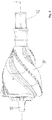
- Figure 6 shows an expansion tool 180 connected to the second connecting element 112, which instead of the expansion tool 24 according to FIGS Figures 1c and 1d can be used.
- a connection element 182 with an opening is provided, which is opposite the expansion tool 180 is freely rotatable and via which a further expansion tool and / or a pipe 26 to be introduced into the expanded opening can be connected.
- Figure 7 shows a sectional illustration of a first connecting element 110a according to a third embodiment.
- the first connecting element 110a can be used both in connection with the adapter arrangement 100 of the first embodiment and in connection with the adapter arrangement 100a of the second embodiment.
- the connecting element 110a also has a check valve 190 which is arranged in an area of the through opening 156 of the first connecting element 110a and which opens the through opening 156 only at a preset minimum rinsing fluid pressure and allows the rinsing fluid 46 to pass through the opening 156.
- Figure 8 shows a sectional view of an adapter arrangement 100b according to a fourth embodiment, the connecting elements 110b, 112, 114 being connected to one another and the connecting element 112 being formed in one piece with the drilling tool 20, 24, 180.
- channels 178 branch off, which lead through parts of the drilling tool 20, 24, 180 to outlet openings or outlet nozzles of the drilling tool 20, 24, 180.
- a check valve 190 can also be arranged in the linkage section of the linkage 14 to which the first connecting element 100, 100a, 100b is connected.
- FIG. 13 shows elements of the check valve 190 according to the third and fourth embodiment according to FIG Figures 7 and 8th in an exploded view.
- the check valve 190 comprises a guide sleeve 192, a closing ball 194, a closing spring 196 and a counterpart for mounting the closing spring 196.
- the closing spring 196 is in particular a spiral compression spring.
- FIG. 11 shows an enlarged sectional illustration of the check valve 190 according to the third embodiment according to FIG Figure 7 when closed.
- the closing ball 194 is pressed by the spring 196 against a closing cone 193 of the guide sleeve 192 so that no rinsing liquid 46 can flow out of the opening 56 of the first connecting element 100b and no dirt can penetrate through the opening 156 into the linkage 14.
- the spring 196 and the ball 194 are dimensioned such that the ball 194 is pressed away from the sealing cone 143 against the spring force of the spring 196 against a second cone 199, which is provided in the counterpart 198, when the minimum flushing pressure is provided.
- the fact that the ball 194 rests on the cone 199 prevents the ball 194 from swinging when the check valve 190 is open.
- Figure 12 shows a sectional exploded view of the elements of the check valve 190.
- the guide sleeve 192 has several guide ribs 200, 202, in particular four, five or six longitudinal ribs for guiding the movement of the closing ball 194 from the closed to the open state and from the open to the closed State has.
- the guide ribs 200, 202 are arranged at equal intervals around the longitudinal axis L and run parallel to the longitudinal axis L.
- rinsing fluid channels 204 to 208 are provided between the guide ribs 200, 202 through which the rinsing fluid 46 is arranged between the guide ribs 200, 202 Closing ball 194 in the open state by the check valve 190 and through the rinsing fluid channels 204 to 208 further into rinsing fluid channels 210 to 218 in the counterpart 198, so that the rinsing fluid 46 reaches the second connecting element 112 and from there to the drilling tool 20, 24, 180.
- first element 100, 100a, 100b can also be connected to the drilling tool 20, 24, 180 and the second element 114 can be connected to the rod 14.
Landscapes
- Engineering & Computer Science (AREA)
- Life Sciences & Earth Sciences (AREA)
- Geology (AREA)
- Mining & Mineral Resources (AREA)
- Mechanical Engineering (AREA)
- Physics & Mathematics (AREA)
- Environmental & Geological Engineering (AREA)
- Fluid Mechanics (AREA)
- General Life Sciences & Earth Sciences (AREA)
- Geochemistry & Mineralogy (AREA)
- Earth Drilling (AREA)
Description
- Die Erfindung betrifft eine Adapteranordnung zum Verbinden eines Bohrwerkzeugs mit einem Bohrgestänge, das ein erstes Element hat, das ein im Bohrgestänge oder dem Bohrwerkzeug verbindbares erstesEnde, einen ersten Gewindeabschnitt mit einem Außengewinde und einem nicht kreisförmigen Querschnitt hat. Das erste Element hat ferner einen an den ersten Gewindeabschnitt angrenzenden oder in einem Abstand zum ersten Gewindeabschnitt angeordneten zylinderförmigen ersten Kontaktbereich. Die Adapteranordnung hat ferner ein zweites Element, das ein mit dem Bohrwerkzeug bzw. mit dem Bohrgestänge verbindbares oder verbundenes zweites Ende und einen zum ersten Gewindeabschnitt komplementären zweiten Gewindeabschnitt mit einem Innengewinde und einem Abschnitt mit nicht kreisförmigem Querschnitt hat. Das zweite Element ist zum Herstellen einer Verbindung mit dem ersten Element geeignet, wobei das zweite Element einen an den zweiten Gewindeabschnitt angrenzenden oder in einem Abstand zum zweiten Gewindeabschnitt angeordneten als zylinderförmige Aussparungen ausgebildeten zweiten Kontaktbereich hat. Das erste Element und das zweite Element sind derart miteinander verbindbar, dass das Gewinde des ersten Gewindeabschnitts und das Gewinde des zweiten Gewindeabschnitts in Eingriff stehen. Die Adapteranordnung umfasst ein drittes Element, das derart ausgebildet und anordenbar ist, dass es im verbundenen Zustand des ersten und des zweiten Elements jeweils einen Bereich des ersten und zweiten Elements mit nicht kreisförmigem Querschnitt umschließt und mit diesen Bereichen in Eingriff steht, wobei der erste Kontaktbereich und der zweite Kontaktbereich derart ausgebildet sind, dass sie bei einer Verbindung des ersten Elements und zweiten Elements in Eingriff stehen. Des Weiteren weisen das erste Element und das zweite Element jeweils eine Öffnung auf, die im verbundenen Zustand des ersten und des zweiten Elements eine Durchgangsöffnung vom ersten Ende zum zweiten Ende bilden, durch die ein Fluid vom Bohrgestänge zum Bohrwerkzeug leitbar ist, und wobei der erste Kontaktbereich mindestens eine umlaufende Nut hat und in die Nut ein Dichtelement eingesetzt ist. Darüber hinaus ist die Erfindung dadurch gekennzeichnet, dass in der Durchgangsöffnung des ersten Elements oder des zweiten Elements ein Rückschlagventil angeordnet ist, welches das Fluid nur vom Bohrgestänge zum Bohrwerkzeug durchlässt.
- Bohrwerkzeuge können hierbei sowohl Bohrköpfe zum Herstellen einer Pilotbohrung als auch Aufweitwerkzeuge zum Aufweiten einer im Erdreich vorhandenen Durchgangsbohrung sein. Die Adapteranordnung wird insbesondere bei gerichteten Horizontalbohrungen (HDD - Horizontal Directional Driling), beispielsweise bei einem Horizontalspülbohrverfahren, eingesetzt. Mit solchen Horizontalbohrverfahren können Rohrleitungen unterirdisch verlegt werden, ohne dazu einen Graben ausheben zu müssen. Eine Horizontalbohrvorrichtung erzeugt eine unterirdische Öffnung im Vortrieb und weitet im Rückzug die Öffnung auf und zieht gleichzeitig ein oder mehrere Rohre ein. Beim Bohren und vorzugsweise beim Aufweiten wird das Bohrwerkzeug üblicherweise gedreht.
- Beim Drehen der Bohrwerkzeuge treten hohe Drehmomente auf, die bei einer Schraubverbindung zwischen dem Bohrgestänge und dem Bohrwerkzeug bzw. bei einem Adapter zum Verbinden des Bohrwerkzeugs mit dem Bohrgestänge eine hohe Anzugskraft bewirken, so dass zum Lösen dieser Verbindung dann erhebliche Kräfte erforderlich sind. Im Stand der Technik sind Adapteranordnungen zum Verbinden von Bohrwerkzeugen und Bohrgestängen bekannt, die eine Schiebehülse haben, die über die Verbindungsstelle zwischen dem Bohrgestänge und dem Bohrwerkzeug geschoben wird und durch die Kontur ihrer Durchgangsöffnung und die Kontur der Mantelfläche der Verbindungselemente der Adapteranordnung dann das Drehmoment zwischen den Verbindungselementen überträgt. Beim Einsatz von Spülflüssigkeit zum Erzeugen der Horizontalbohrung wird diese durch ein aus mehreren Gestängeabschnitten zusammengesetztes Gestänge über die Verbindungsanordnung bis zum Bohrwerkzeug geleitet. An der Verbindungsstelle zwischen den Verbindungselementen tritt dann das Problem auf, dass Bohrflüssigkeit insbesondere bei einer seitlichen Krafteinwirkung auf das Gestänge bzw. auf die Adapteranordnung austreten und insbesondere in einen Gewindeabschnitt zum Verbinden der Verbindungselemente eintreten und diesen schädigen kann.
- Aus dem Dokument
DE 101 15 233 A1 ist eine Horizontalbohranlage bekannt, bei der eine Hochdruckpumpe zum Zuführen von Spülflüssigkeit zum Bohrgestänge und eine Mischeinrichtung zum Aufbereiten der Spülflüssigkeit mit einem eine Mischpumpe aufweisenden Mischaggregat auf dem Fahrwerk der Horizontalbohranlage angeordnet sind. - Aus dem Dokument
DE 10 2015 107 194 A1 ist eine Bohranlage zum Erzeugen oder Aufweiten einer Erdbohrung bekannt, bei der der Vortrieb des Gestänges abhängig vom Drehmoment zur Rotation des Gestänges geregelt wird. Beim Vorschub des Bohrwerkzeugs kann Spülflüssigkeit durch das Bohrgestänge zum Bohrkopf geleitet werden. Weitere Horizontalbohranlagen mit einem Vorschubantrieb zum Antrieb eines ein Bohrwerkzeug tragenden Bohrgestänges, das unter gleichzeitiger Drehung mit Hilfe eines Vorschubantriebs im Erdreich vorgeschoben wird, sind aus den DokumentenDE 10 2010 004 287 A1 undUS 6,189,628 B1 bekannt. - Dokument
DE 199 01 001 A1 offenbart eine Erdbohranlage, bei der ein Antriebsschlitten zum Antrieb eines Bohrgestänges vorgesehen ist, der zum Zuführen von Spülflüssigkeit einen entsprechenden Anschluss hat. - Dokument
US 2012/0267170 A1 und Dokument2017/0074051 A1 offenbaren jeweils eine Anordnung zum Verbinden eines Bohrwerkzeugs mit einem Gestänge, bei denen eine Verbindung mit niedrigem Drehmoment und verbesserter Festigkeit und Haltbarkeit herstellbar ist. - Dokument
DE 601 32 645 T2 offenbart einen Zementverrohrungsschuh für ein Einzeldurchmesserbohrloch, bei dem innerhalb des als Werkzeug dienenden Zementverohrungsschuhs ein Ventil vorgesehen ist, durch das ein Fördermedium aus dem Bohrloch in einen Rohrabschnitt des Werkzeugs selbst gelangt. - Es ist Aufgabe der Erfindung, eine Adapteranordnung zum Verbinden eines Bohrwerkzeugs mit einem Bohrgestänge anzugeben. die eine sichere Verbindung ermöglicht.
- Diese Aufgabe wird durch eine Adapteranordnung zum Verbinden eines Bohrwerkzeugs mit den Merkmalen des Anspruchs 1 gelöst. Vorteilhafte Weiterbildungen sind in den abhängigen Ansprüchen angegeben.
- Insbesondere durch das Vorsehen des mit dem zweiten Kontaktbereich in Eingriff stehenden ersten Kontaktbereichs können Kräfte quer zur Längsachse des Gestänges und zur Längsachse des Adapters zwischen dem ersten und dem zweiten Element sicher übertragen werden, so dass im Bereich der Adapteranordnung keine oder nur eine geringe Durchbiegung bei einer seitlichen Krafteinwirkung auf die Adapteranordnung erfolgt, so dass eine stabile und in Verbindung mit dem Dichtelement dichte Verbindung zwischen dem ersten Element und dem zweiten Element auch bei großen auf die Adapteranordnung wirkenden Kräften sichergestellt ist.
- Besonders vorteilhaft ist es, wenn der erste Kontaktbereich und der zweite Kontaktbereich derart ausgebildet sind, dass sie bei einer Verbindung des ersten Elements und des zweiten Elements derart in Eingriff stehen, dass bei einer Krafteinwirkung quer zur Längsachse des Gestänges eine Kraft quer zur Längsachse zwischen dem ersten Kontaktbereich und dem zweiten Kotaktbereich übertragen wird. Hierdurch wird eine stabile und sichere Verbindung zwischen dem ersten Element und dem zweiten Element erreicht.
- Ferner ist es vorteilhaft, wenn der erste Gewindeabschnitt zwischen dem ersten Kontaktbereich und einem zylinderförmigen dritten Kontaktbereich angeordnet ist und wenn der zweite Gewindeabschnitt zwischen dem zweiten Kontaktbereich und einem in einer weiteren zylinderförmigen Aussparung gebildeten vierten Kontaktbereich angeordnet ist. Der dritte Kontaktbereich und der vierte Kontaktbereich sind dann derart ausgebildet, dass sie bei einer Verbindung des ersten Elements und des zweiten Elements in Eingriff stehen.
- Hierdurch wird erreicht, dass die Krafteinwirkungen auf die in Eingriff stehenden Gewindeabschnitte des ersten Elements und des zweiten Elements bei einer Krafteinwirkung quer zur Längsachse des Gestänges gering gehalten werden.
- Ferner ist es vorteilhaft, wenn der dritte Kontaktbereich und der vierte Kontaktbereich derart ausgebildet sind, dass sie bei einer Verbindung des ersten Elements und des zweiten Elements derart in Eingriff stehen, dass bei einer Krafteinwirkung quer zur Längsachse des Gestänges eine Kraft quer zur Längsachse zwischen dem dritten Kontaktbereich und dem vierten Kontaktbereich übertragen wird. Hierdurch wird sichergestellt, dass bei Krafteinwirkungen quer zur Längsachse des Gestänges sowohl Kräfte über den ersten und den zweiten Kontaktbereich als auch über den dritten und vierten Kontaktbereich übertragen werden, so dass die Adapteranordnung selbst relativ große Querkräfte aufnehmen kann, ohne dass die Adapteranordnung selbst durchgebogen und die Stabilität und Dichtheit der Verbindung beeinträchtigt wird.
- Weiterhin ist es vorteilhaft, wenn der erste Kontaktbereich und der zweite Kontaktbereich eine Passung, insbesondere eine Presspassung, Spielpassung oder Übergangspassung, bilden. Alternativ oder zusätzlich können der dritte Kontaktbereich und der vierte Kontaktbereich eine Passung, insbesondere eine Presspassung, Spielpassung oder Übergangspassung, bilden. Hierdurch ist sichergestellt, dass jeweils komplementäre Kontaktbereiche derart ausgebildet sind, dass sie bereits bei geringen auf die Adapteranordnung einwirkenden Querkräften sicher aneinander anliegen und entsprechende Querkräfte übertragen.
- Besonders vorteilhaft ist es, wenn der Durchmesser des ersten Kontaktbereichs um einen Wert im Bereich von 6/100 mm bis 8/100 mm kleiner als der Durchmesser des zweiten Kontaktbereichs ist. Alternativ oder zusätzlich kann der Durchmesser des dritten Kontaktbereichs um einen Wert im Bereich von 6/100 mm bis 8/100 mm kleiner sein als der Durchmesser des vierten Kontaktbereichs. Hierdurch ist eine sichere Kraftübertragung zwischen den Kontaktbereichen möglich.
- Besonders vorteilhaft ist es, wenn das Dichtelement derart in die Umlaufnut eingesetzt ist, dass ein Teil des Dichtelements umlaufend aus der Nut hervorsteht. Dadurch kann das Dichtelement beim Verbinden des ersten Elements mit dem zweiten Element zusammengedrückt werden und eine besonders gute Dichtwirkung erzielen. Durch das Komprimieren des Dichtelements im verbundenen Zustand des ersten und des zweiten Elements kann das Dichtelement zumindest in Bereichen entspannt bzw. dekomprimiert werden, wenn aufgrund der Kraftübertragung zwischen dem ersten Kontaktbereich und dem zweiten Kontaktbereich ein Spalt in Teilbereichen zwischen dem ersten Kontaktbereich und dem zweiten Kontaktbereich entsteht oder vergrößert wird, so dass das Dichtelement auch in diesem Zustand sicher dichtet.
- Besonders vorteilhaft ist es, wenn der erste Kontaktbereich mindestens eine zweite umlaufende Nut hat, in die ein zweites Dichtelement eingesetzt ist. Vorzugsweise ist das zweite Dichtelement derart in die umlaufende Nut eingesetzt, dass ein Teil des Dichtelements umlaufend aus der Nut hervorsteht. Das erste und/oder das zweite Dichtelement sind vorzugsweise als O-Ring ausgeführt. Hierdurch kann ein sicheres und vielfach bewährtes Dichtelement auch zum Abdichten der Adapteranordnung eingesetzt werden.
- Ferner können im dritten Kontaktbereich eine oder zwei Nuten vorgesehen sein, in denen jeweils ein Dichtelement eingesetzt ist, das vorzugsweise elastisch verformbar ist und von denen vorzugsweise jeweils ein Teil des Dichtelements umlaufend aus der Nut hervorsteht. Hierdurch ist eine zweiseitige Abdichtung des ersten und zweiten Gewindeabschnitts einfach und sicher möglich.
- Besonders vorteilhaft ist es, wenn das erste Element und das zweite Element jeweils im Bereich mit nicht kreisförmigem Querschnitt einen Außenvielkant oder Außenvielzahn, vorzugsweise einen Außensechskant, haben. Das dritte Element hat vorzugsweise zu den Bereichen mit nicht rundem Querschnitt des ersten Elements und des zweiten Elements eine komplementäre Öffnung. Diese Öffnung ist insbesondere als Innenvielkant, Innenvielzahn, insbesondere als Innensechskant, ausgebildet.
- Dadurch ist eine einfache Möglichkeit geschaffen, einen Eingriff der Bereiche mit nicht rundem Querschnitt des ersten Elements und des zweiten Elements mit dem dritten Element sicherzustellen, so dass eine Drehung des ersten Elements relativ zum zweiten Element um die Längsachse des Gestänges nicht möglich ist und die Drehmomentübertragung zwischen dem ersten Element und dem zweiten Element im Wesentlichen über das dritte Element erfolgt.
- Ferner ist es vorteilhaft, wenn das dritte Element als Schiebehülse ausgebildet ist und im verbundenen Zustand vorzugsweise mit mindestens einer Sicherungsschraube und/oder mindestens einem Sicherungsstift, insbesondere mindestens einem Spannstift oder Schwerspannstift mit dem ersten und/oder zweiten Element verbindbar ist, wobei der Sicherungsstift in eine Öffnung, vorzugsweise eine umlaufende Nut, im ersten Element oder im zweiten Element eingreift. Hierdurch ist eine einfache Ausbildung und Sicherung des dritten Elements möglich, so dass das dritte Element gegen Verrutschen gesichert ist, so dass sicher verhindert wird, dass sich die Schiebehülse nur noch mit dem ersten Element oder mit dem zweiten Element oder mit keinem dieser Elemente in Eingriff steht. Durch den Eingriff in eine umlaufende Nut kann eine Drehung des ersten Elements gegenüber dem dritten Element bzw. des zweiten Elements gegenüber dem dritten Element ermöglicht werden, insbesondere eine Drehbewegung zwischen dem ersten und dem dritten Element bzw. zwischen dem zweiten und dem dritten Element in Folge einer Drehmomentübertragung zwischen dem ersten Element und dem dritten Element bzw. dem zweiten Element und dem dritten Element und bei einem Spiel zwischen dem nicht kreisförmigen Querschnittbereich des ersten Elements und des dritten Elements und/oder dem nicht kreisförmigen Querschnittbereich des zweiten Elements und des dritten Elements.
- Ferner ist es vorteilhaft, wenn sowohl das Innengewinde als auch das Außengewinde keglige Gewinde sind. Dies können insbesondere NPT-Gewinde (NPT = National Pipe Thread), Whitworth-Gewinde oder metrische kegelige Gewinde sein. Hierdurch können die Gewindeabschnitte beim Verbinden des ersten Elements und des zweiten Elements abdichten, so dass zusätzlich zum vorgesehenen Dichtelement eine weitere Dichtfunktion vorhanden ist, um insbesondere ein Durchströmen der miteinander verbundenen Gewindebereiche mit Spülflüssigkeit zu verhindern.
- Besonders vorteilhaft ist es, wenn in der Durchgangsöffnung des ersten Elements oder des zweiten Elements ein Rückschlagventil angeordnet ist, das Fluid, insbesondere Spülflüssigkeit, nur vom Bohrgestänge zum Bohrwerkzeug durchlässt. Hierdurch ist sichergestellt, dass bei einer Trennung des ersten Elements vom zweiten Element kein Schmutz oder Spülflüssigkeit in das mit dem jeweiligen Element verbundene Bohrgestänge bzw. mit dem Element verbundene Bohrwerkzeug eindringen kann. Auch wird mit Hilfe des Rückschlagventils verhindert, dass die durch das hohle Bohrgestänge gebildete Rohrleitung durch austretende Spülflüssigkeit leer wird, wenn keine Spülflüssigkeit in das Gestänge eingeleitet wird.
- Besonders vorteilhaft ist es, wenn das Rückschlagventil ein Schließelement, ein elastisch verformbares Element und einen Dichtkonus umfasst, wobei das elastisch verformbare Element das Schließelement im geschlossenen Zustand des Rückschlagventils gegen den Dichtkonus drückt und/oder wenn das elastisch verformbare Element im geöffneten Zustand des Rückschlagventils durch einen durch das Rückschlagventil fließenden Fluidstrom derart verformt wird, dass das Schließelement gegen einen zweiten Konus gedrückt wird. Hierdurch wird sichergestellt, dass das Schließelement sowohl im geöffneten Zustand des Rückschlagventils als auch im geschlossenen Zustand des Rückschlagventils sicher in seiner Position, d.h. in der geschlossenen Position und in der geöffneten Position des Rückschlagventils verbleibt. Dabei ist es vorteilhaft, wenn das Schließelement eine Kugel und das elastisch verformbare Element eine Feder oder ein Elastomerblock ist. Die Feder ist insbesondere eine Spiralfeder, vorzugsweise eine Druckfeder. Hierdurch ist ein einfacher kostengünstiger und sicherer Aufbau der Adapteranordnung möglich.
- Weitere Merkmale und Vorteile ergeben sich aus der folgenden Beschreibung, die die Erfindung anhand von Ausführungsbeispielen im Zusammenhang mit den beigefügten Figuren näher erläutert.
- Es zeigen:
- Figur 1A
- eine schematische Darstellung einer Bohranlage zum gesteuerten Bohren einer Pilotbohrung, mit der eine Durchgangsöffnung im Erdreich erzeugt wird, die nachfolgend mithilfe eines Aufweitwerkzeugs aufweitbar ist;
- Figur 1B
- einen vergrößerten Ausschnitt der Bohranlage nach
Figur 1A , wobei der Bohrkopf zum Erzeugen der Pilotbohrung dargestellt ist; - Figur 1C
- eine schematische Darstellung einer Bohranlage zum Aufweiten der mit der Bohranlage nach
Figur 1A erzeugten Pilotbohrung mithilfe eines Aufweitwerkzeugs; - Figur 1D
- einen vergrößerten Ausschnitt der Bohranlage nach
Figur 1C , wobei das Aufweitwerkzeug zum Aufweiten der Pilotbohrung dargestellt ist; - Figur 2
- eine Adapteranordnung, bei der die Verbindungselemente der Adapteranordnung getrennt voneinander angeordnet sind, gemäß einer ersten Ausführungsform;
- Figur 3
- eine Schnittdarstellung der Adapteranordnung nach
Figur2 im verbundenen Zustand der Verbindungselemente; - Figur 4
- eine Adapteranordnung 100a, bei der die Verbindungselemente getrennt voneinander angeordnet sind, gemäß einer zweiten Ausführungsform;
- Figur 5
- eine Schnittdarstellung der Adapteranordnung nach
Figur 4 , bei der die Verbindungselemente der Adapteranordnung miteinander verbunden sind; - Figur 6
- ein mit einem Aufweitwerkzeug verbundenes Verbindungselement der Adapteranordnung nach den
Figuren 2 bis 5 ; - Figur 7
- eine Schnittdarstellung eines Verbindungselements einer weiteren Adapteranordnung gemäß einer dritten Ausführungsform;
- Figur 8
- eine Schnittdarstellung einer Adapteranordnung gemäß einer vierten Ausführungsform, wobei die Verbindungselemente der Adapteranordnung miteinander verbunden sind;
- Figur 9
- Elemente eines Rückschlagventils gemäß der dritten und vierten Ausführungsform nach den
Figuren 7 und8 in einer Explosionsdarstellung; - Figur 10
- eine vergrößerte Schnittdarstellung des Rückschlagventils gemäß der dritten Ausführungsform nach
Figur 7 im geschlossenen Zustand; - Figur 11
- das Rückschlagventil nach
Figur 10 in einem geöffneten Zustand; und - Figur 12
- eine perspektivische Explosions-Schnitt-Darstellung der Elemente des Rückschlagventils nach
Figur 11 . - In
Figur 1A ist eine Bohranlage 10 zum gesteuerten Bohren einer Pilotbohrung gezeigt. Die Bohranlage 10 arbeitet nach einem gesteuerten Horizontalbohrverfahren, das auch als Horizontal Directional Drilling (HDD) Verfahren bezeichnet wir. Im vorliegenden Ausführungsbeispiel wird hierzu eine unter der Handelsbezeichnung Terra-Jet erhältliche Horizontalbohranlage eingesetzt. Eine solche Horizontalbohranlage ist beispielsweise aus dem DokumentDE 101 15 233 A1 bekannt. Beim HDD-Verfahren wird ein aus mehreren Gestängeabschnitten 13 zusammengesetztes Gestänge 14 mithilfe eines Horizontalbohrgerätes 12 an einem Startpunkt 16 mit einem an dem Horizontalbohrgerät 12 entfernten Ende des Gestänges 14 angeordneten Bohrkopf 20 in Richtung des Pfeils P0 in das Erdreich 18 eingebracht. Das Horizontalbohrgerät 12 hat eine Pumpe 42, die über einen Schlauch 48 Spülflüssigkeit 46 aus einem Spülflüssigkeitsbehälter 40 ansaugt und mit hohem Druck in das hohle Gestänge 14 fördert. Die Spülflüssigkeit 46 tritt mit hohem Druck am Bohrkopf 20 aus. Durch den hohen Druck und durch Hartmetallzähne des Bohrkopfs 20 wird ein Bohrloch ins Erdreich 18 geschnitten. - Der Bohrkopf 20 ist an seinem vorderen Ende asymmetrisch abgeflacht und wird mithilfe des Gestänges 14 zum Erzeugen eines geraden Bohrlochs kontinuierlich gedreht. Bei einer gewünschten seitlichen Bewegung, Aufwärtsbewegung oder Abwärtsbewegung wird der Bohrkopf 20 in einer für diese gewünschte Bewegung geeigneten Position angehalten und nicht weitergedreht, so dass aufgrund der asymmetrisch abgeflachten Form des vorderen Endes des Bohrkopfs 20 eine entsprechende Ablenkbewegung des Bohrkopfs 20 im Erdreich 18 erfolgt. In
Figur 1B ist eine Detailansicht des von dem Horizontalbohrgerät 12 entfernten Endes des Gestänges 14 zusammen mit dem Bohrkopf 20 gezeigt. Im Bohrkopf 20 ist eine elektronische Sonde angeordnet, die mithilfe eines entsprechenden Ortungsgerätes jederzeit von der Erdoberfläche aus exakt geortet werden kann, so dass die Position des Bohrkopfs 20 im Erdreich 18 jederzeit exakt bestimmbar ist. - Die Bewegungsbahn des Bohrkopfs 20 und damit der Verlauf des Bohrkanals 15 der Pilotbohrung wird einfach durch kontrolliertes Stoppen der Drehung des Bohrkopfs 20 über das Gestänge 14 gesteuert, so dass die Steuerfläche des Bohrkopfs 20 in eine für die gewünschte Bewegung erforderliche Stellung gebracht wird. Auch nach dem gezielten Stoppen der Drehung des Bohrkopfs 20 wird mit Hilfe der Pumpe 42 weiterhin Spülflüssigkeit 46 durch das Gestänge 14 gefördert und der Bohrkopf 20 wird weiter über das Gestänge 14 vorangetrieben, so dass mithilfe der Spülflüssigkeit 46 und des Vortriebs des Bohrkopfs 20 der Bohrvorgang des gewünschten Verlaufs des Bohrlochs fortgesetzt wird.
- Nach Erreichen des Zielpunkts 22, der beispielsweise in einer Zielgrube vorgesehen ist, wird der Bohrkopf 20 durch einen Aufweitkopf 24 ersetzt, der beim Zurückziehen des Gestänges 14 die zuvor erzeugte Pilotbohrung aufweitet und gleichzeitig ein HDPE-Rohr 26 einzieht, wie dies in den
Figuren 1C und 1D gezeigt ist. HDPE-Rohre sind aus High-Density-Polyethylen hergestellt, wobei dieses High-Density-Polyethylen ein thermoplastischer Kunststoff mit hoher Dichte ist, so dass die aus HDPE hergestellten Rohre eine hohe Zähigkeit und Steifigkeit, eine sehr gute chemische Beständigkeit, gute Gleiteigenschaften, geringe Feuchtigkeitsaufnahme, sehr gute Verarbeitungseigenschaften, sehr gut verschweißbar sind und physiologisch unbedenklich sind. Bei anderen Ausführungsformen können auch Rohre 26 aus anderen Materialien, insbesondere aus Metall, eingezogen werden. - Das Horizontalbohrgerät 12 erzeugt die für den Aufweitvorgang erforderliche Zugkraft am Gestänge 14 und leitet weiterhin Spülflüssigkeit 46 zum Aufweitkopf 24.
- Die Spülflüssigkeit 46 unterstützt zumindest das Aufweiten der Pilotbohrung und dient ferner zum Ableiten und Austragen des beim Aufweitvorgang gelösten überschüssigen Erdreichs 18. Insbesondere bei steinigem Erdreich 18, Geröll und Fels muss zumindest ein Teil des mithilfe des Aufweitwerkzeugs 24 beim Aufweitvorgang kontaktierten Erdreichs 18 abgeführt werden. Dies kann insbesondere durch den Ringspalt zwischen dem als Bohrkanal 15 bezeichneten bereits aufgeweiteten Bereich der Pilotbohrung und dem eingezogenen Rohr 26 erfolgen. Die in den Ringspalt eingebrachte Spülflüssigkeit 46 verringert auch die Mantelreibung zwischen dem Rohr 26 und dem Bohrkanal 15.
- Gleichzeitig mit dem Aufweitvorgang wird das neu zu verlegende Rohr 26, im vorliegenden Fall ein HDPE-Rohr, eingezogen. Je nach Untergrund können auch zwei oder mehr Aufweitwerkzeuge 24 nacheinander mit bis zu einem Durchmesser von üblicherweise von bis zu 1000 mm eingesetzt werden. Es können dann dann Rohre 26 bis zu einem Durchmesser von 800 mm oder ein Rohrbündel aus mehreren Rohren eingezogen. Als Spülflüssigkeit 46 kann Wasser mit Betonit oder Polymeren eingesetzt werden. Solche Spülflüssigkeiten 46 stabilisieren den Bohrkanal 15, vermindern die Reibung zwischen Bohrgestänge 14 und Erdreich 18 sowie die Reibung zwischen dem einzuziehenden Rohr 26 und dem Erdreich 18. Ferner wird mithilfe der Spülflüssigkeit 46 Erdreich 18 durch das bereits zum Teil eingezogene Rohr 26 aus dem Bohrkanal 15 herausgefördert.
-
Figur 1D zeigt einen vergrößerten Ausschnitt der inFigur 1C gezeigten Anordnung 10. In diesem Ausschnitt sind das von dem Horizontalbohrgerät 12 entfernte Ende des Gestänges 14, der Aufweitkopf 24 und das bereits zum Teil ins Erdreich 18 eingezogene Rohr 26 dargestellt. - Eine Steuereinheit 50 des Horizontalbohrgeräts 12, insbesondere eine speicherprogrammierbare Steuereinheit (SPS), steuert die Pumpe 42 zum Fördern der Spülflüssigkeit 46 durch das Gestänge 14 an. Die Pumpe 42 ist durch die Steuereinheit 50 insbesondere derart ansteuerbar, dass der Volumenstrom der durch die Pumpe 42 geförderten und somit der am Bohr- bzw. Aufweitkopf 20, 24 austretenden Spülflüssigkeit 46 steuerbar ist.
- Das Horizontalbohrgerät 12 hat vorzugsweise einen Drehantrieb zum Drehen des Gestänges 14 um eine Längsachse und den Vorschubantrieb zum Bewegen des Gestänges 14 entlang seiner Längsachse durch das Erdreich 18 zusammen mit dem an dem vom Vorschubantrieb entfernten Ende des Gestänges 14 mit diesem verbundenen Bohrkopf 20 oder Aufweitkopf 24.
- Die Verbindung zwischen Gestänge 14 und Bohrkopf 20 sowie zwischen Gestänge 14 und Aufweitkopf 24 erfolgt über eine Adapteranordnung 100, die nachfolgend in Verbindung mit den
Figuren 2 bis 12 noch näher erläutert wird. -
Figur 2 zeigt eine perspektivische Darstellung der Adapteranordnung 100. Die Adapteranordnung 100 umfasst ein erstes Verbindungselement 110, das mit einem ersten Gestängeabschnitt des Gestänges 14 verbunden ist, sowie ein zweites Verbindungselement 112, das mit einem Bohrwerkzeug, wie einem Bohrkopf 20 oder einem Aufweitkopf 24, verbunden ist. Ferner hat die Adapteranordnung 100 ein drittes Verbindungselement 114, das über einen Bereich mit nicht zylinderförmiger Mantelfläche 116 des ersten Verbindungselements 110 und über einen Bereich mit nicht zylinderförmiger Mantelfläche 118 des zweiten Verbindungselements geschoben werden kann. Im folgenden Ausführungsbeispiel haben die Bereiche 116, 118 jeweils einen sechskantförmigen Querschnitt, wobei die Querschnittsöffnung 120 des dritten Verbindungselements 114 einen zu den Außenquerschnitten der Bereiche 118, 116 komplementären Innenquerschnitt hat, so dass ein Drehmoment vom Gestänge 14 auf das Bohrwerkzeug 20 im Wesentlichen über das dritte Verbindungselement 114 übertragbar ist. Das erste Verbindungselement 110 hat ferner einen Abschnitt 122 mit einem geringeren Querschnitt als der nicht zylinderförmige Bereich 116, so dass das dritte Verbindungselement 114 zumindest teilweise über den Abschnitt 122 geschoben werden kann, so dass es außer Eingriff mit dem nicht zylinderförmigen Bereich 118 des zweiten Verbindungselements 112 kommt, um dieses relativ zum ersten Verbindungselement 110 zu drehen. Hierdurch ist ein Verbinden und Trennen des ersten und zweiten Verbindungselements 110, 112 möglich. Das dritte Verbindungselement kann so verschoben werden, dass es beide nicht zylinderförmige Bereiche 116, 118 des ersten Verbindungselements und des zweiten Verbindungselements zumindest teilweise umschließt. Das dritte Verbindungselement wird auch als Schiebehülse bezeichnet. In diesem Zustand ist die Übertragung von großen Drehmomenten zwischen dem Gestänge 14 und Bohrwerkzeug 20, 24 möglich. - Ferner umfasst die Adapteranordnung 100 zwei Sicherungsschrauben 124, 126, die durch jeweils eine Durchgangsöffnung 130 im dritten Verbindungselement 114 in jeweils ein im ersten Verbindungselement 110 vorhandenes mit einem Innengewinde versehenes Loch 129 schraubbar sind, um das dritte Verbindungselement 114 im verbundenen Zustand an einer korrekten Position zu halten. Im nicht zylinderförmigen Verbindungsbereich 116 des ersten Verbindungselements 110 ist weiterhin eine Nut vorgesehen, in die in Öffnungen 130, 131 des dritten Verbindungselements 114 eingeführte Sicherungsstifte im verbundenen Zustand der Elemente 110, 112, 114 der Adapteranordnung 100 eingreifen. Diese Sicherungsstifte können alternativ oder zusätzlich zu den Sicherungsschrauben 124, 126 vorgesehen werden, wie dies nachfolgend noch näher erläutert wird.
- Das erste Verbindungselement 110 hat ferner einen Bereich mit einem konischen Außengewinde 132, das mit einem konischen Innengewinde im zweiten Verbindungselement 112 verbindbar ist, wie dies nachfolgende näher erläutert wird.
Fig.3 zeigt eine Schnittdarstellung der Adapteranordnung 100 nachFig.2 im verbundenen Zustand der Verbindungselemente 110, 112, 114. Das Außengewinde 132 des ersten Verbindungselements 110 steht mit einem Innengewinde 134 in Eingriff, so dass eine Schraubverbindung zwischen dem ersten und dem zweiten Element 110, 112 besteht. Der Eingriff der inneren Querschnittsöffnung des dritten Verbindungselements 114 mit den Bereichen 116, 118 verhindert eine weitere Drehung des ersten Verbindungselements 110 und des zweiten Verbindungselements 112 relativ zueinander, so dass auch die Schraubverbindung zwischen den Gewindeabschnitten 132, 134 bei einer Drehmomentenübertragung zwischen dem ersten Verbindungselement 110 und dem zweiten Verbindungselement 112 nicht weiter mit größeren Kräften miteinander verschraubt werden. - Das erste Verbindungselement 110 hat einen ersten zylinderförmigen Kontaktbereich 136, der mit einem durch eine zylinderförmige Öffnung im zweiten Verbindungselement 112 gebildeten zweiten Kontaktbereich 138 in Eingriff steht. Im ersten zylinderförmigen Kontaktbereich 136 sind zwei umlaufende Nuten 140, 142 vorhanden, in denen jeweils ein Dichtelement 144, 146 angeordnet ist. Über die Kontaktbereiche 136, 138 können insbesondere quer zur Längsachse L der Adapteranordnung 100 wirkende Kräfte zwischen dem ersten Verbindungselement 110 und dem zweiten Verbindungselement 112 übertragen werden. Ferner umfasst das erste Verbindungselement 110 einen dritten Kontaktbereich 148, der mit einer weiteren in der zylinderförmigen Öffnung des zweiten Verbindungselements 112 vorhandenen Kontaktbereich 150 in Eingriff steht. Auch über den dritten Kontaktbereich 148 und den vierten Kontaktbereich 150 können Kräfte quer zur Längsachse der Adapteranordnung 100 übertragen werden. Wie in
Fig.3 ersichtlich ist, sind die Sicherungsschrauben 124, 126 als Inbusschrauben ausgeführt. - Die Gewindeabschnitte 132, 134 sowie die Kontaktbereiche 136, 138, 148, 150 sind derart angeordnet und ausgebildet, dass keine Flächen 152, 154 in einer Ebene quer zur Längsachse der Adapteranordnung 100 vorgesehen sind, die sich im verbundenen Zustand der Verbindungselemente 110, 112, 114 so kontaktieren, dass sie bei einer geringfügigen weiteren Drehbewegung des ersten Verbindungselements 110 relativ zum zweiten Verbindungselement 112 gegeneinander gedrückt werden. Vielmehr sind das erste und das zweite Verbindungselement 110, 112 derart ausgebildet und im verbundenen Zustand derart angeordnet, dass zwischen solchen Flächen 152, 154 ein Spalt 155 verbleibt. Dadurch wird ein Lösen der Schraubverbindung über die Gewindeabschnitte 132, 134 vereinfacht, wenn die Verbindungselemente 110, 112, 114 wieder getrennt werden sollen.
- Der erste Gewindeabschnitt 132 ist zwischen dem ersten Kontaktbereich 136 und dem dritten Kontaktbereich 148 angeordnet. Der zweite Gewindeabschnitt 134 ist somit zwischen dem zweiten Kontaktbereich 138 und dem Kontaktbereich 150 angeordnet. Sowohl das erste Verbindungselement 110 als auch das zweite Verbindungselement 112 haben jeweils durchgehende zylinderförmige Öffnungen 156, 158, durch die Spülflüssigkeit 46, die durch eine innere Durchgangsöffnung des Gestänges 14 über die Durchgangsöffnung 156, 158 der Adapteranordnung 100 bis zum Bohrwerkzeug 20, 24 geleitet wird.
- Wie in
Figur 2 zu sehen ist, hat das dritte Verbindungselement zwei ringförmige Erhebungen 160, 162, die in Richtung der Längsachse L der Adapteranordnung 100 in einem Abstand zueinander angeordnet sind und mehrere Erhebungen 164 bis 168, die vorzugsweise in gleichen Winkelabständen, um das dritte Verbindungselement 114 herum an dessen Mantelfläche angeordnet sind. Hierdurch kann das dritte Verbindungselement 114 auch bei widrigen Umgebungsbedingungen, insbesondere bei einem Baustellenbetrieb, bei dem Spülflüssigkeit 46 außen an der Adapteranordnung 100 anhaftet, von einer Bedienperson betätigt, insbesondere gedreht und verschoben werden. Bei der ersten Ausführungsform nach denFiguren 2 und 3 erfolgt eine Sicherung des dritten Verbindungselements 114 nur mit Hilfe der Sicherungsschrauben 124, 126 und nicht mit Hilfe zusätzlicher Sicherungsstifte. -
Figur 4 zeigt eine Adapteranordnung 100a, bei der die Verbindungselemente 110, 112, 114 getrennt voneinander angeordnet sind, gemäß einer zweiten Ausführungsform. Gleiche Elemente haben gleiche Bezugszeichen. Im Unterschied zur ersten Ausführungsform nach denFiguren 2 und3 sind bei der zweiten Ausführungsform zwei Sicherungsstifte 170, 172 vorgesehen, die insbesondere als Spannstifte, beispielsweise als Schwerspannstifte ausgeführt sind und die in die entsprechenden Öffnungen 130, 131 des dritten Verbindungselements 114 eingebracht werden, nachdem die Verbindungselemente 110, 112, 114 miteinander verbunden worden sind. Vorzugsweise werden die Spannstifte 170 172 bzw. die Schwerspannstifte, 170, 172 in die Öffnungen 130, 131 eingeschlagen. Die Verwendung der Stifte 170, 172 sind im verbundenen Zustand durch die im Bereich 116 eingebrachte Nut 174 geführt. Bei anderen Ausführungsformen kann anstelle der Nut 174 lediglich eine Aussparung in dem Bereich vorgesehen sein, in dem die Stifte 170, 172 das erste Verbindungselement 110 kontaktieren. -
Figur 5 zeigt eine Schnittdarstellung der Adapteranordnung 100a nachFigur 4 , wobei die Schnittebene inFigur 4 in einer horizontalen Ebene liegt. In dieser Schnittdarstellung nachFigur 5 sind die Verbindungselemente 110, 112, 114 in einem verbundenen Zustand dargestellt. Die Spannstifte 170, 172 sind hierbei durch einen Bereich der Nut 174 geführt. -
Figur 6 zeigt ein mit dem zweiten Verbindungselement 112 verbundenes Aufweitwerkzeug 180, das anstelle des Aufweitwerkzeugs 24 nach denFiguren 1c und 1d eingesetzt werden kann. An dem entlang der Längsachse im Verbindungselement 112 gegenüberliegenden Ende des Aufweitwerkzeugs 180 ist ein Verbindungselement 182 mit einer Öffnung vorgesehen, die gegenüber dem Aufweitwerkzeug 180 frei drehbar ist und über die ein weiteres Aufweitwerkzeug und/oder ein in die aufgeweitete Öffnung einzubringendes Rohr 26 verbunden werden kann. -
Figur 7 zeigt eine Schnittdarstellung eines ersten Verbindungselements 110a gemäß einer dritten Ausführungsform. Das erste Verbindungselement 110a kann sowohl in Verbindung mit der Adapteranordnung 100 der ersten Ausführungsform als auch in Verbindung mit der Adapteranordnung 100a der zweiten Ausführungsform eingesetzt werden. Im Unterschied zu dem Verbindungselement 110 hat das Verbindungselement 110a zusätzlich ein Rückschlagventil 190, das in einem Bereich der durchgehenden Öffnung 156 des ersten Verbindungselements 110a angeordnet ist und die Durchgangsöffnung 156 erst bei einem voreingestellten Mindestspülflüssigkeitsdruck öffnet und die Spülflüssigkeit 46 durch die Öffnung 156 hindurchlässt. -
Figur 8 zeigt eine Schnittdarstellung einer Adapteranordnung 100b gemäß einer vierten Ausführungsform, wobei die Verbindungselemente 110b, 112, 114 miteinander verbunden sind und das Verbindungselement 112 einstückig mit dem Bohrwerkzeug 20, 24, 180 ausgebildet ist. Am Ende der Durchgangsöffnung 158 im zweiten Verbindungselement 112 zweigen Kanäle 178 ab, die durch Teile des Bohrwerkzeugs 20, 24, 180 hindurch bis zu Austrittsöffnungen bzw. Austrittsdüsen des Bohrwerkzeugs 20, 24, 180 führen. Bei dem ersten Verbindungselement 100b ist im Unterschied zu dem ersten Verbindungselement 100a nachFigur 7 der Abstand zwischen dem vorderen Ende des ersten Elements 110a und dem Rückschlagventil 190 vergrößert. Bei anderen Ausführungsformen kann auch ein Rückschlagventil 190 in dem Gestängeabschnitt des Gestänges 14 angeordnet sein, mit dem das erste Verbindungselement 100, 100a, 100b verbunden ist. -
Figur 9 zeigt Elemente des Rückschlagsventils 190 gemäß der dritten und vierten Ausführungsform nach denFiguren 7 und8 in einer Explosionsdarstellung. Das Rückschlagventil 190 umfasst eine Führungshülse 192, eine Schließkugel 194, eine Schließfeder 196 und ein Gegenstück zur Lagerung der Schließfeder 196. Die Schließfeder 196 ist insbesondere eine Spiraldruckfeder. -
Figur 10 zeigt eine vergrößerte Schnittdarstellung des Rückschlagventils 190 gemäß der dritten Ausführungsform nachFigur 7 in geschlossenem Zustand. Die Schließkugel 194 wird durch die Feder 196 gegen einen Schließkonus 193 der Führungshülse 192 gedrückt, so dass keine Spülflüssigkeit 46 aus der Öffnung 56 des ersten Verbindungselements 100b herausfließen kann und kein Schmutz durch die Öffnung 156 in das Gestänge 14 eindringen kann. Die Feder 196 und die Kugel 194 sind derart dimensioniert, dass die Kugel 194 bei einem vorgesehenen Mindestspüldruck weg vom Dichtkonus 143 entgegen der Federkraft der Feder 196 gegen einen zweiten Konus 199, der im Gegenstück 198 vorgesehen ist, gedrückt wird. Durch die Anlage der Kugel 194 am Konus 199 wird ein Schwingen der Kugel 194 im geöffneten Zustand des Rückschlagventils 190 vermieden. - Fließt die Spülflüssigkeit 46 durch die Führungshülse 192, wird die Kugel 194 nach vorne gegen die Federkraft der Feder 196 bewegt und gegen den Konus 199 gedrückt, wie dies in
Figur 11 gezeigt ist. Die Spülflüssigkeit 46 fließt an der Schließkugel 194 vorbei und durch Öffnungen im Gegenstück 198 weiter zum zweiten Verbindungselement 112 und durch dieses zum Bohrwerkzeug 20, 24, 180 hindurch. - Wird beispielsweise bei einem Gestängewechsel, d.h. beim Hinzufügen eines weiteren Gestängeabschnitts zum Gestänge 14 oder beim Entfernen eines Gestängeabschnitts vom Gestänge 14, die Spülflüssigkeitspumpe 42 abgestellt, sinkt der Spüldruck auf Umgebungsdruck und die Federkraft der Feder 196 drückt die Schließkugel 194 gegen den Dichtkonus 193, so dass die Schließkugel 194 in der in
Figur 10 dargestellten Position angeordnet ist. -
Figur 12 zeigt eine geschnittene Explosionsdarstellung der Elemente des Rückschlagventils 190. Hierbei ist erkennbar, dass die Führungshülse 192 mehrere Führungsrippen 200, 202, insbesondere vier, fünf oder sechs Längsrippen zur Führung der Bewegung der Schließkugel 194 vom geschlossenen in den geöffneten Zustand und vom geöffneten in den geschlossenen Zustand hat. Die Führungsrippen 200, 202 sind in gleichen Abständen um die Längsachse L herum angeordnet und verlaufen parallel zur Längsachse L. Gleichzeitig sind zwischen den Führungsrippen 200, 202 Spülflüssigkeitskanäle 204 bis 208 vorgesehen, durch die die Spülflüssigkeit 46 an der zwischen den Führungsrippen 200, 202 angeordneten Schließkugel 194 im geöffneten Zustand des Rückschlagventils 190 vorbei und durch die Spülflüssigkeitskanäle 204 bis 208 weiter in Spülflüssigkeitskanäle 210 bis 218 im Gegenstück 198, so dass die Spülflüssigkeit 46 in das zweite Verbindungselement 112 und von dort zum Bohrwerkzeug 20, 24, 180 gelangt. - Bei alternativen Ausführungsformen kann das erste Element 100, 100a, 100b auch mit dem Bohrwerkzeug 20, 24, 180 und das zweite Element 114 mit dem Gestänge 14 verbunden sein.
-
- 10
- Bohranlage
- 12
- Horizontalbohrgerät
- 13
- Gestängeabschnitte
- 14
- Gestänge
- 15
- Bohrkanal
- 16
- Startpunkt
- 18
- Erdreich
- 20,24
- Bohrwerkzeug
- 22
- Zielpunkt
- 26
- Rohr
- 40
- Spülflüssigkeitsbehälter
- 42
- Pumpe
- 46
- Spülflüssigkeit
- 48
- Schlauch
- 50
- Steuereinheit
- 56
- Öffnung
- 100, 100a
- Adapteranordnung
- 110, 110a
- erstes Verbindungselement
- 112
- zweites Verbindungselement
- 114
- drittes Verbindungselement
- 116, 118
- Bereich
- 120
- Querschnittsöffnung
- 122
- Abschnitt
- 124, 126
- Sicherungsschraube
- 129
- Loch
- 130, 131
- Öffnung
- 132,134
- Gewindeabschnitt
- 136, 138, 148, 150
- Kontaktbereich
- 140, 142
- Nut
- 143
- Dichtkonus
- 144, 146
- Dichtelement
- 152, 154
- Fläche
- 155
- Spalt
- 156, 158
- Öffnung
- 160, 162, 164 bis 168
- Erhebung
- 170, 172
- Sicherungsstift
- 174
- Nut
- 178
- Kanäle
- 180
- Bohrwerkzeug
- 182
- Verbindungselement
- 190
- Rückschlagventil
- 192
- Führungshülse
- 193
- Dichtkonus
- 194
- Schließkugel
- 196
- Schließfeder
- 198
- Gegenstück
- 199
- zweiter Konus
- 200, 202, 204 bis 208
- Führungsrippe
- 210 bis 218
- Spülflüssigkeitskanal
- L
- Längsachse
Claims (14)
- Adapteranordnung zum Verbinden eines Bohrwerkzeugs mit einem Bohrgestänge,
mit einem ersten Element (110), das ein mit dem Bohrgestänge (14) oder mit dem Bohrwerkzeug (20, 24, 180) verbindbares oder verbundenes erstes Ende, einen ersten Gewindeabschnitt (132) mit einem Außengewinde und einen Abschnitt (116) mit einem nichtkreisförmigen Querschnitt hat, wobei das erste Element (110) einen an den ersten Gewindeabschnitt (132) angrenzenden oder in einem Abstand zum ersten Gewindeabschnitt (132) angeordneten zylinderförmigen ersten Kontaktbereich (136) hat,
mit einem zweiten Element (112), das ein mit dem Bohrwerkzeug (20, 24, 180) verbindbares oder verbundenes zweites Ende und einen zum ersten Gewindeabschnitt (132) komplementären zweiten Gewindeabschnitt (134) mit einem Innengewinde (134) und einem Abschnitt (118) mit nichtkreisförmigen Querschnitt hat und das zum Herstellen einer Verbindung mit dem ersten Element (110) geeignet ist, wobei das zweite Element (112) einen an den zweiten Gewindeabschnitt (134) angrenzenden oder in einem Abstand zum zweiten Gewindeabschnitt (134) angeordneten als zylinderförmige Aussparung ausgebildeten zweiten Kontaktbereich (138) hat,
wobei das erste Element (110) und das zweite Element (112) derart miteinander verbindbar sind, dass das Gewinde des ersten Gewindeabschnitts (132) und das Gewinde des zweiten Gewindeabschnitts (134) in Eingriff stehen,
mit einem dritten Element (114), das derart ausgebildet und anordenbar ist, dass es im verbundenen Zustand des ersten und zweiten Elements (110, 112) jeweils einen Bereich (116, 118) des ersten und zweiten Elements (110, 112) mit nichtkreisförmigen Querschnitt umschließt und mit diesen Bereichen (116, 118) in Eingriff steht,
wobei der erste Kontaktbereich (136) und der zweite Kontaktbereich (138) derart ausgebildet sind, dass sie bei einer Verbindung des ersten Elements (110) und zweiten Elements (112) in Eingriff stehen,
wobei das erste Element (110) und das zweite Element (112) jeweils eine Öffnung (156, 158) aufweisen, die im verbundenen Zustand des ersten und des zweiten Elements (110, 112) eine Durchgangsöffnung vom ersten Ende zum zweiten Ende bilden, durch die ein Fluid (46) vom Bohrgestänge (14) zum Bohrwerkzeug (20, 24, 18) leitbar ist, und
wobei der erste Kontaktbereich (136) mindestens eine umlaufende Nut (140, 142) hat und in die Nut (140, 142) ein Dichtelement (144, 146) eingesetzt ist dadurch gekennzeichnet, dass
in der Durchgangsöffnung (156, 158) des ersten Elements (110) oder des zweiten Elements (112) ein Rückschlagventil (190) angeordnet ist, das Fluid (46) nur vom Bohrgestänge (14) zum Bohrwerkzeug (20, 24, 180) durchlässt. - Adapteranordnung nach Anspruch 1, dadurch gekennzeichnet, dass der erste Kontaktbereich (136) und der zweite Kontaktbereich (138) derart ausgebildet sind, dass sie bei einer Verbindung des ersten Elements (110) und zweiten Elements (112) derart in Eingriff stehen, dass bei einer Krafteinwirkung quer zur Längsachse (L) des Gestänges (14) eine Kraft quer zur Längsachse (L) zwischen dem ersten Kontaktbereich (136) und dem zweiten Kontaktbereich (138) übertragen wird.
- Adapteranordnung nach Anspruch 1 oder 2, dadurch gekennzeichnet, dass der erste Gewindeabschnitt (132) zwischen dem ersten Kontaktbereich (136) und einem zylinderförmigen dritten Kontaktbereich (148) angeordnet ist, dass der zweite Gewindeabschnitt (134) zwischen dem zweiten Kontaktbereich (138) und einem in einer weiteren zylinderförmigen Aussparung gebildeten vierten Kontaktbereich (150) angeordnet ist, wobei der dritte Kontaktbereich (148) und der vierte Kontaktbereich (150) derart ausgebildet sind, dass sie bei einer Verbindung des ersten Elements (110) und zweiten Elements (112) in Eingriff stehen.
- Adapteranordnung nach Anspruch 3, dadurch gekennzeichnet, dass der dritte Kontaktbereich (148) und der vierte Kontaktbereich (150) derart ausgebildet sind, dass sie bei einer Verbindung des ersten Elements (110) und zweiten Elements (112) derart in Eingriff stehen, dass bei einer Krafteinwirkung quer zur Längsachse (L) des Gestänges (14) eine Kraft quer zur Längsachse (L) zwischen dem dritten Kontaktbereich (148) und dem vierten Kontaktbereich (150) übertragen wird.
- Adapteranordnung nach einem der vorhergehenden Ansprüche, dadurch gekennzeichnet, dass der erste Kontaktbereich (136) und der zweite Kontaktbereich (138) eine Passung, insbesondere eine Presspassung, Spielpassung oder Übergangspassung, bilden und/oder dass der dritte Kontaktbereich (148) und der vierte Kontaktbereich (150) eine Passung, insbesondere eine Presspassung, Spielpassung oder Übergangspassung, bilden.
- Adapteranordnung nach einem der vorhergehenden Ansprüche, dadurch gekennzeichnet, dass der Durchmesser des ersten Kontaktbereichs (136) um einen Wert im Bereich von 6/100 mm bis 8/100 mm kleiner ist als der Durchmesser des zweiten Kontaktbereichs (138) und/oder
dass der Durchmesser des dritten Kontaktbereichs (148) um einen Wert im Bereich von 6/100 mm bis 8/100 mm kleiner ist als der Durchmesser des vierten Kontaktbereichs (150). - Adapteranordnung nach einem der vorhergehenden Ansprüche, dadurch gekennzeichnet, dass des Dichtelement(144, 146) derart in die umlaufende Nut (140, 142) eingesetzt ist, dass ein Teil des Dichtelements (144, 146) umlaufend aus der Nut (140, 142) hervorsteht.
- Adapteranordnung nach einem der vorhergehenden Ansprüche, dadurch gekennzeichnet, dass das Dichtelement (144, 146) elastisch verformbar ist.
- Adapteranordnung nach einem der vorhergehenden Ansprüche, dadurch gekennzeichnet, dass der erste Kontaktbereich (136) mindestens eine zweite umlaufende Nut (142) hat, in die ein zweites Dichtelement (146) eingesetzt ist.
- Adapteranordnung nach einem der vorhergehenden Ansprüche, dadurch gekennzeichnet, dass das erste Element (110) und das zweite Element (112) jeweils im Bereich (116, 118) mit nichtkreisförmigem Querschnitt ein Außenvielkant oder Außenvielzahn, vorzugsweise ein Außensechskant, hat, und
dass das dritte Element (114) eine zu den Bereichen (116, 118) mit nichtrundem Querschnitt des ersten Elements (110) und des zweiten Elements (112) komplementäre Öffnung (120) hat, die insbesondere als Innenvielkant oder Innenvielzahn, vorzugsweise als Innensechskant, ausgebildet ist. - Adapteranordnung nach einem der vorhergehenden Ansprüche, dadurch gekennzeichnet, dass das dritte Element (114) als Schiebehülse ausgebildet ist und im Verbundenen Zustand vorzugsweise mit mindestens einer Sicherungsschraube (124, 126) und/oder mindestens einem Sicherungsstift (170, 172), insbesondere mindestens einem Spannstift oder Schwerspannstift, mit dem ersten und/oder zweiten Element (110, 112) verbindbar ist, wobei der Sicherungsstift in eine Öffnung, vorzugsweise in eine umlaufende Nut (174), im ersten Element (110) oder im zweiten Element (112) eingreift.
- Adapteranordnung nach einem der vorhergehenden Ansprüche, dadurch gekennzeichnet, dass sowohl das Innengewinde (134) als auch das Außengewinde (132) kegelige Gewinde, insbesondere NPT-Gewinde (National Pipe Thread), Whitworth-Gewinde oder metrische kegelige Gewinde, sind.
- Adapteranordnung nach einem der vorhergehenden Ansprüche, dadurch gekennzeichnet, dass das Rückschlagventil (190) ein Schließelement (194), ein elastisch verformbares Element (196) und einen Dichtkonus (193) umfasst, wobei das elastisch verformbare Element (196) das Schließelement (194) im geschlossenen Zustand des Rückschlagventils (190) gegen den Dichtkonus (193) drückt und/oder wobei das elastisch verformbare Element derart angeordnet und ausgebildet ist, dass das Schließelement (194) im geöffneten Zustand des Rückschlagventils (190) durch einen durch das Rückschlagventil (190) fließenden Fluidstrom (46) gegen einen zweiten Konus (199) drückbar ist.
- Adapteranordnung nach Anspruch 13, dadurch gekennzeichnet, dass das Schließelement eine Kugel (194) und das elastisch verformbare Element eine Feder (196) oder ein Elastomerblock ist.
Priority Applications (1)
| Application Number | Priority Date | Filing Date | Title |
|---|---|---|---|
| PL19209324T PL3660260T3 (pl) | 2018-11-28 | 2019-11-15 | Układ adaptera do łączenia narzędzia wiertniczego z przewodem wiertniczym |
Applications Claiming Priority (1)
| Application Number | Priority Date | Filing Date | Title |
|---|---|---|---|
| DE102018130065.4A DE102018130065A1 (de) | 2018-11-28 | 2018-11-28 | Adapteranordnung zum Verbinden eines Bohrwerkzeugs mit einem Bohrgestänge |
Publications (2)
| Publication Number | Publication Date |
|---|---|
| EP3660260A1 EP3660260A1 (de) | 2020-06-03 |
| EP3660260B1 true EP3660260B1 (de) | 2021-09-15 |
Family
ID=68583114
Family Applications (1)
| Application Number | Title | Priority Date | Filing Date |
|---|---|---|---|
| EP19209324.3A Active EP3660260B1 (de) | 2018-11-28 | 2019-11-15 | Adapteranordnung zum verbinden eines bohrwerkzeugs mit einem bohrgestänge |
Country Status (3)
| Country | Link |
|---|---|
| EP (1) | EP3660260B1 (de) |
| DE (1) | DE102018130065A1 (de) |
| PL (1) | PL3660260T3 (de) |
Family Cites Families (7)
| Publication number | Priority date | Publication date | Assignee | Title |
|---|---|---|---|---|
| DE19901001C2 (de) | 1999-01-13 | 2002-09-12 | Terra Ag Fuer Tiefbautechnik S | Erdbohranlage mit Gestängewechsler |
| DE10115233C5 (de) | 2000-05-11 | 2011-09-15 | TERRA AG für Tiefbautechnik | Horizontalbohranlage |
| US6845820B1 (en) * | 2000-10-19 | 2005-01-25 | Weatherford/Lamb, Inc. | Completion apparatus and methods for use in hydrocarbon wells |
| DE102010004287A1 (de) | 2010-01-11 | 2011-07-14 | TERRA AG für Tiefbautechnik | Verfahren und Anordnung zum Herstellen und/oder Aufweiten einer Erdbohrung |
| US8991490B2 (en) * | 2010-12-01 | 2015-03-31 | Vermeer Manufacturing Company | Tapered thread configuration with improved durability |
| DE102015107194A1 (de) | 2015-05-08 | 2016-11-10 | TERRA AG für Tiefbautechnik | Bohranlage zum Erzeugen oder Aufweiten einer Erdbohrung im Erdreich und Verfahren zur Steuerung eines Vorschubantriebs einer solchen Bohranlage |
| US10167680B2 (en) * | 2015-09-10 | 2019-01-01 | Hunting Energy Services, Inc. | Multi-lead quick connect threaded connection |
-
2018
- 2018-11-28 DE DE102018130065.4A patent/DE102018130065A1/de not_active Withdrawn
-
2019
- 2019-11-15 EP EP19209324.3A patent/EP3660260B1/de active Active
- 2019-11-15 PL PL19209324T patent/PL3660260T3/pl unknown
Also Published As
| Publication number | Publication date |
|---|---|
| PL3660260T3 (pl) | 2022-01-17 |
| EP3660260A1 (de) | 2020-06-03 |
| DE102018130065A1 (de) | 2020-05-28 |
Similar Documents
| Publication | Publication Date | Title |
|---|---|---|
| DE60023504T2 (de) | Schraubverbindung für rohre | |
| AT391009B (de) | Rohrverbindung | |
| DE3882953T2 (de) | Rammbohrgerät mit Kontrollventil. | |
| EP0397874A1 (de) | Vorrichtung zum schliessen einer schwierigkeitszone in einem bohrloch | |
| EP2085566A2 (de) | Bohranlage | |
| DE3415627A1 (de) | Rohrpruefgeraet | |
| DE3923579A1 (de) | Anschlussarmatur fuer rohre, insbesondere fuer kunststoffrohre | |
| DE19803304C2 (de) | Bohrgestänge zum Drehschlagbohren, insbesondere zum Überlagerungsbohren | |
| DE19749007C2 (de) | Vorrichtung zum Verbinden eines Nachziehrohres mit einem Ziehgerät | |
| EP4067716B1 (de) | Rohrabschnittsmontagevorrichtung | |
| EP3660260B1 (de) | Adapteranordnung zum verbinden eines bohrwerkzeugs mit einem bohrgestänge | |
| DE102014204598A1 (de) | Zweistahlschraube mit Fließpressverbindung | |
| WO2009092659A2 (de) | Injektionskopf | |
| EP4403740B1 (de) | Gewindeverbindung | |
| EP3480419B1 (de) | Schneckenbohreranordnung und verfahren zum bilden einer schneckenbohreranordnung | |
| EP2420646A1 (de) | Rohrverbindung | |
| DE10065533B4 (de) | Gestängekupplung für Gestängeschüsse mit einem Medienkanal | |
| DE19629459C2 (de) | Anbohrarmatur für Kunststoffrohre | |
| EP0310601A1 (de) | Vorrichtung zum anschluss eines druckmessgerätes an eine rohrleitung. | |
| DE19747250C1 (de) | Verbindungsstück zum Einziehen von Rohrleitungen | |
| DE19918530A1 (de) | Verfahren und Kupplung zur Verbindung zweier Abschnitte eines Bohrgestänges | |
| DE10123058A1 (de) | Erdbohrvorrichtung | |
| DE102020005980A1 (de) | Steuerbarer Bohrkopf | |
| DE3207183C1 (de) | Rohrverbindung für Metallrohre | |
| DE102005045050A1 (de) | Rohreinzugsadapter mit Dichtkissen |
Legal Events
| Date | Code | Title | Description |
|---|---|---|---|
| PUAI | Public reference made under article 153(3) epc to a published international application that has entered the european phase |
Free format text: ORIGINAL CODE: 0009012 |
|
| STAA | Information on the status of an ep patent application or granted ep patent |
Free format text: STATUS: THE APPLICATION HAS BEEN PUBLISHED |
|
| AK | Designated contracting states |
Kind code of ref document: A1 Designated state(s): AL AT BE BG CH CY CZ DE DK EE ES FI FR GB GR HR HU IE IS IT LI LT LU LV MC MK MT NL NO PL PT RO RS SE SI SK SM TR |
|
| AX | Request for extension of the european patent |
Extension state: BA ME |
|
| STAA | Information on the status of an ep patent application or granted ep patent |
Free format text: STATUS: REQUEST FOR EXAMINATION WAS MADE |
|
| 17P | Request for examination filed |
Effective date: 20201124 |
|
| RBV | Designated contracting states (corrected) |
Designated state(s): AL AT BE BG CH CY CZ DE DK EE ES FI FR GB GR HR HU IE IS IT LI LT LU LV MC MK MT NL NO PL PT RO RS SE SI SK SM TR |
|
| GRAP | Despatch of communication of intention to grant a patent |
Free format text: ORIGINAL CODE: EPIDOSNIGR1 |
|
| STAA | Information on the status of an ep patent application or granted ep patent |
Free format text: STATUS: GRANT OF PATENT IS INTENDED |
|
| INTG | Intention to grant announced |
Effective date: 20210412 |
|
| GRAS | Grant fee paid |
Free format text: ORIGINAL CODE: EPIDOSNIGR3 |
|
| GRAA | (expected) grant |
Free format text: ORIGINAL CODE: 0009210 |
|
| STAA | Information on the status of an ep patent application or granted ep patent |
Free format text: STATUS: THE PATENT HAS BEEN GRANTED |
|
| AK | Designated contracting states |
Kind code of ref document: B1 Designated state(s): AL AT BE BG CH CY CZ DE DK EE ES FI FR GB GR HR HU IE IS IT LI LT LU LV MC MK MT NL NO PL PT RO RS SE SI SK SM TR |
|
| REG | Reference to a national code |
Ref country code: CH Ref legal event code: EP |
|
| REG | Reference to a national code |
Ref country code: DE Ref legal event code: R096 Ref document number: 502019002293 Country of ref document: DE |
|
| REG | Reference to a national code |
Ref country code: IE Ref legal event code: FG4D Free format text: LANGUAGE OF EP DOCUMENT: GERMAN Ref country code: NL Ref legal event code: FP |
|
| REG | Reference to a national code |
Ref country code: AT Ref legal event code: REF Ref document number: 1430661 Country of ref document: AT Kind code of ref document: T Effective date: 20211015 |
|
| REG | Reference to a national code |
Ref country code: LT Ref legal event code: MG9D |
|
| PG25 | Lapsed in a contracting state [announced via postgrant information from national office to epo] |
Ref country code: SE Free format text: LAPSE BECAUSE OF FAILURE TO SUBMIT A TRANSLATION OF THE DESCRIPTION OR TO PAY THE FEE WITHIN THE PRESCRIBED TIME-LIMIT Effective date: 20210915 Ref country code: RS Free format text: LAPSE BECAUSE OF FAILURE TO SUBMIT A TRANSLATION OF THE DESCRIPTION OR TO PAY THE FEE WITHIN THE PRESCRIBED TIME-LIMIT Effective date: 20210915 Ref country code: BG Free format text: LAPSE BECAUSE OF FAILURE TO SUBMIT A TRANSLATION OF THE DESCRIPTION OR TO PAY THE FEE WITHIN THE PRESCRIBED TIME-LIMIT Effective date: 20211215 Ref country code: LT Free format text: LAPSE BECAUSE OF FAILURE TO SUBMIT A TRANSLATION OF THE DESCRIPTION OR TO PAY THE FEE WITHIN THE PRESCRIBED TIME-LIMIT Effective date: 20210915 Ref country code: FI Free format text: LAPSE BECAUSE OF FAILURE TO SUBMIT A TRANSLATION OF THE DESCRIPTION OR TO PAY THE FEE WITHIN THE PRESCRIBED TIME-LIMIT Effective date: 20210915 Ref country code: HR Free format text: LAPSE BECAUSE OF FAILURE TO SUBMIT A TRANSLATION OF THE DESCRIPTION OR TO PAY THE FEE WITHIN THE PRESCRIBED TIME-LIMIT Effective date: 20210915 Ref country code: NO Free format text: LAPSE BECAUSE OF FAILURE TO SUBMIT A TRANSLATION OF THE DESCRIPTION OR TO PAY THE FEE WITHIN THE PRESCRIBED TIME-LIMIT Effective date: 20211215 |
|
| PG25 | Lapsed in a contracting state [announced via postgrant information from national office to epo] |
Ref country code: LV Free format text: LAPSE BECAUSE OF FAILURE TO SUBMIT A TRANSLATION OF THE DESCRIPTION OR TO PAY THE FEE WITHIN THE PRESCRIBED TIME-LIMIT Effective date: 20210915 Ref country code: GR Free format text: LAPSE BECAUSE OF FAILURE TO SUBMIT A TRANSLATION OF THE DESCRIPTION OR TO PAY THE FEE WITHIN THE PRESCRIBED TIME-LIMIT Effective date: 20211216 |
|
| PG25 | Lapsed in a contracting state [announced via postgrant information from national office to epo] |
Ref country code: IS Free format text: LAPSE BECAUSE OF FAILURE TO SUBMIT A TRANSLATION OF THE DESCRIPTION OR TO PAY THE FEE WITHIN THE PRESCRIBED TIME-LIMIT Effective date: 20220115 Ref country code: SM Free format text: LAPSE BECAUSE OF FAILURE TO SUBMIT A TRANSLATION OF THE DESCRIPTION OR TO PAY THE FEE WITHIN THE PRESCRIBED TIME-LIMIT Effective date: 20210915 Ref country code: SK Free format text: LAPSE BECAUSE OF FAILURE TO SUBMIT A TRANSLATION OF THE DESCRIPTION OR TO PAY THE FEE WITHIN THE PRESCRIBED TIME-LIMIT Effective date: 20210915 Ref country code: RO Free format text: LAPSE BECAUSE OF FAILURE TO SUBMIT A TRANSLATION OF THE DESCRIPTION OR TO PAY THE FEE WITHIN THE PRESCRIBED TIME-LIMIT Effective date: 20210915 Ref country code: PT Free format text: LAPSE BECAUSE OF FAILURE TO SUBMIT A TRANSLATION OF THE DESCRIPTION OR TO PAY THE FEE WITHIN THE PRESCRIBED TIME-LIMIT Effective date: 20220117 Ref country code: ES Free format text: LAPSE BECAUSE OF FAILURE TO SUBMIT A TRANSLATION OF THE DESCRIPTION OR TO PAY THE FEE WITHIN THE PRESCRIBED TIME-LIMIT Effective date: 20210915 Ref country code: EE Free format text: LAPSE BECAUSE OF FAILURE TO SUBMIT A TRANSLATION OF THE DESCRIPTION OR TO PAY THE FEE WITHIN THE PRESCRIBED TIME-LIMIT Effective date: 20210915 Ref country code: CZ Free format text: LAPSE BECAUSE OF FAILURE TO SUBMIT A TRANSLATION OF THE DESCRIPTION OR TO PAY THE FEE WITHIN THE PRESCRIBED TIME-LIMIT Effective date: 20210915 Ref country code: AL Free format text: LAPSE BECAUSE OF FAILURE TO SUBMIT A TRANSLATION OF THE DESCRIPTION OR TO PAY THE FEE WITHIN THE PRESCRIBED TIME-LIMIT Effective date: 20210915 |
|
| REG | Reference to a national code |
Ref country code: DE Ref legal event code: R097 Ref document number: 502019002293 Country of ref document: DE |
|
| PG25 | Lapsed in a contracting state [announced via postgrant information from national office to epo] |
Ref country code: MC Free format text: LAPSE BECAUSE OF FAILURE TO SUBMIT A TRANSLATION OF THE DESCRIPTION OR TO PAY THE FEE WITHIN THE PRESCRIBED TIME-LIMIT Effective date: 20210915 |
|
| PLBE | No opposition filed within time limit |
Free format text: ORIGINAL CODE: 0009261 |
|
| STAA | Information on the status of an ep patent application or granted ep patent |
Free format text: STATUS: NO OPPOSITION FILED WITHIN TIME LIMIT |
|
| PG25 | Lapsed in a contracting state [announced via postgrant information from national office to epo] |
Ref country code: LU Free format text: LAPSE BECAUSE OF NON-PAYMENT OF DUE FEES Effective date: 20211115 Ref country code: DK Free format text: LAPSE BECAUSE OF FAILURE TO SUBMIT A TRANSLATION OF THE DESCRIPTION OR TO PAY THE FEE WITHIN THE PRESCRIBED TIME-LIMIT Effective date: 20210915 Ref country code: BE Free format text: LAPSE BECAUSE OF NON-PAYMENT OF DUE FEES Effective date: 20211130 |
|
| REG | Reference to a national code |
Ref country code: BE Ref legal event code: MM Effective date: 20211130 |
|
| 26N | No opposition filed |
Effective date: 20220616 |
|
| PG25 | Lapsed in a contracting state [announced via postgrant information from national office to epo] |
Ref country code: SI Free format text: LAPSE BECAUSE OF FAILURE TO SUBMIT A TRANSLATION OF THE DESCRIPTION OR TO PAY THE FEE WITHIN THE PRESCRIBED TIME-LIMIT Effective date: 20210915 |
|
| PG25 | Lapsed in a contracting state [announced via postgrant information from national office to epo] |
Ref country code: IE Free format text: LAPSE BECAUSE OF NON-PAYMENT OF DUE FEES Effective date: 20211115 |
|
| PG25 | Lapsed in a contracting state [announced via postgrant information from national office to epo] |
Ref country code: IT Free format text: LAPSE BECAUSE OF FAILURE TO SUBMIT A TRANSLATION OF THE DESCRIPTION OR TO PAY THE FEE WITHIN THE PRESCRIBED TIME-LIMIT Effective date: 20210915 |
|
| PG25 | Lapsed in a contracting state [announced via postgrant information from national office to epo] |
Ref country code: CY Free format text: LAPSE BECAUSE OF FAILURE TO SUBMIT A TRANSLATION OF THE DESCRIPTION OR TO PAY THE FEE WITHIN THE PRESCRIBED TIME-LIMIT Effective date: 20210915 |
|
| PG25 | Lapsed in a contracting state [announced via postgrant information from national office to epo] |
Ref country code: HU Free format text: LAPSE BECAUSE OF FAILURE TO SUBMIT A TRANSLATION OF THE DESCRIPTION OR TO PAY THE FEE WITHIN THE PRESCRIBED TIME-LIMIT; INVALID AB INITIO Effective date: 20191115 |
|
| PG25 | Lapsed in a contracting state [announced via postgrant information from national office to epo] |
Ref country code: MK Free format text: LAPSE BECAUSE OF FAILURE TO SUBMIT A TRANSLATION OF THE DESCRIPTION OR TO PAY THE FEE WITHIN THE PRESCRIBED TIME-LIMIT Effective date: 20210915 |
|
| PG25 | Lapsed in a contracting state [announced via postgrant information from national office to epo] |
Ref country code: TR Free format text: LAPSE BECAUSE OF FAILURE TO SUBMIT A TRANSLATION OF THE DESCRIPTION OR TO PAY THE FEE WITHIN THE PRESCRIBED TIME-LIMIT Effective date: 20210915 |
|
| PG25 | Lapsed in a contracting state [announced via postgrant information from national office to epo] |
Ref country code: MT Free format text: LAPSE BECAUSE OF FAILURE TO SUBMIT A TRANSLATION OF THE DESCRIPTION OR TO PAY THE FEE WITHIN THE PRESCRIBED TIME-LIMIT Effective date: 20210915 |
|
| REG | Reference to a national code |
Ref country code: CH Ref legal event code: U11 Free format text: ST27 STATUS EVENT CODE: U-0-0-U10-U11 (AS PROVIDED BY THE NATIONAL OFFICE) Effective date: 20251201 |
|
| PGFP | Annual fee paid to national office [announced via postgrant information from national office to epo] |
Ref country code: NL Payment date: 20251119 Year of fee payment: 7 |
|
| PGFP | Annual fee paid to national office [announced via postgrant information from national office to epo] |
Ref country code: DE Payment date: 20251127 Year of fee payment: 7 |
|
| PGFP | Annual fee paid to national office [announced via postgrant information from national office to epo] |
Ref country code: GB Payment date: 20251120 Year of fee payment: 7 |
|
| PG25 | Lapsed in a contracting state [announced via postgrant information from national office to epo] |
Ref country code: AT Free format text: LAPSE BECAUSE OF NON-PAYMENT OF DUE FEES Effective date: 20241115 |
|
| PGFP | Annual fee paid to national office [announced via postgrant information from national office to epo] |
Ref country code: FR Payment date: 20251120 Year of fee payment: 7 |
|
| REG | Reference to a national code |
Ref country code: AT Ref legal event code: MM01 Ref document number: 1430661 Country of ref document: AT Kind code of ref document: T Effective date: 20241115 |
|
| PGFP | Annual fee paid to national office [announced via postgrant information from national office to epo] |
Ref country code: CH Payment date: 20251201 Year of fee payment: 7 |
|
| PGFP | Annual fee paid to national office [announced via postgrant information from national office to epo] |
Ref country code: PL Payment date: 20251014 Year of fee payment: 7 |
|
| PGFP | Annual fee paid to national office [announced via postgrant information from national office to epo] |
Ref country code: AT Payment date: 20260410 Year of fee payment: 5 |