EP3660260B1 - Agencement d'adaptateur permettant de raccorder un outil de forage à une tige de forage - Google Patents
Agencement d'adaptateur permettant de raccorder un outil de forage à une tige de forage Download PDFInfo
- Publication number
- EP3660260B1 EP3660260B1 EP19209324.3A EP19209324A EP3660260B1 EP 3660260 B1 EP3660260 B1 EP 3660260B1 EP 19209324 A EP19209324 A EP 19209324A EP 3660260 B1 EP3660260 B1 EP 3660260B1
- Authority
- EP
- European Patent Office
- Prior art keywords
- contact region
- adapter arrangement
- arrangement according
- threaded portion
- opening
- Prior art date
- Legal status (The legal status is an assumption and is not a legal conclusion. Google has not performed a legal analysis and makes no representation as to the accuracy of the status listed.)
- Active
Links
Images





Classifications
-
- E—FIXED CONSTRUCTIONS
- E21—EARTH OR ROCK DRILLING; MINING
- E21B—EARTH OR ROCK DRILLING; OBTAINING OIL, GAS, WATER, SOLUBLE OR MELTABLE MATERIALS OR A SLURRY OF MINERALS FROM WELLS
- E21B17/00—Drilling rods or pipes; Flexible drill strings; Kellies; Drill collars; Sucker rods; Cables; Casings; Tubings
- E21B17/02—Couplings; joints
- E21B17/03—Couplings; joints between drilling rod or pipe and drill motor or surface drive, e.g. between drilling rod and hammer
-
- E—FIXED CONSTRUCTIONS
- E21—EARTH OR ROCK DRILLING; MINING
- E21B—EARTH OR ROCK DRILLING; OBTAINING OIL, GAS, WATER, SOLUBLE OR MELTABLE MATERIALS OR A SLURRY OF MINERALS FROM WELLS
- E21B17/00—Drilling rods or pipes; Flexible drill strings; Kellies; Drill collars; Sucker rods; Cables; Casings; Tubings
- E21B17/02—Couplings; joints
- E21B17/04—Couplings; joints between rod or the like and bit or between rod and rod or the like
- E21B17/042—Threaded
-
- E—FIXED CONSTRUCTIONS
- E21—EARTH OR ROCK DRILLING; MINING
- E21B—EARTH OR ROCK DRILLING; OBTAINING OIL, GAS, WATER, SOLUBLE OR MELTABLE MATERIALS OR A SLURRY OF MINERALS FROM WELLS
- E21B17/00—Drilling rods or pipes; Flexible drill strings; Kellies; Drill collars; Sucker rods; Cables; Casings; Tubings
- E21B17/02—Couplings; joints
- E21B17/04—Couplings; joints between rod or the like and bit or between rod and rod or the like
- E21B17/046—Couplings; joints between rod or the like and bit or between rod and rod or the like with ribs, pins, or jaws, and complementary grooves or the like, e.g. bayonet catches
Definitions
- the invention relates to an adapter arrangement for connecting a drilling tool to a drill string, which has a first element which has a first end connectable in the drill string or the drilling tool, a first threaded section with an external thread and a non-circular cross-section.
- the first element also has a cylindrical first contact area adjoining the first thread section or at a distance from the first thread section.
- the adapter arrangement furthermore has a second element which has a second end which can be or is connected to the drilling tool or to the drill rod and a second thread section which is complementary to the first thread section and has an internal thread and a section with a non-circular cross section.
- the second element is suitable for establishing a connection with the first element, wherein the second element has a second contact area which is in the form of cylindrical recesses, adjacent to the second threaded section or arranged at a distance from the second threaded section.
- the first element and the second element can be connected to one another in such a way that the thread of the first threaded section and the thread of the second threaded section are in engagement.
- the adapter arrangement comprises a third element which is designed and can be arranged such that, in the connected state of the first and the second element, it encloses a region of the first and second element with a non-circular cross section and is in engagement with these regions, the first contact region and the second contact region are configured such that they are in engagement when the first element and the second element are connected.
- the first element and the second element each have an opening which, in the connected state of the first and the second element, form a through opening from the first end to the second end, through which a fluid can be conducted from the drill rod to the drilling tool, and wherein the first Contact area has at least one circumferential groove and a sealing element is inserted into the groove.
- the invention is characterized in that a check valve is arranged in the through opening of the first element or of the second element, which only allows the fluid to pass from the drill rod to the drilling tool.
- Drilling tools can both drill heads for making a pilot hole as well as widening tools for widening an existing through hole in the ground.
- the adapter arrangement is used in particular for directed horizontal drilling (HDD - Horizontal Directional Driling), for example in a horizontal directional drilling process.
- HDD directed horizontal drilling
- pipelines can be laid underground without having to dig a trench.
- a horizontal drilling device creates a subterranean opening in the drive and, in the retreat, widens the opening and pulls in one or more pipes at the same time. When drilling and preferably when expanding, the drilling tool is usually rotated.
- adapter assemblies for connecting drilling tools and drill rods which have a sliding sleeve which is pushed over the connection point between the drill rod and the drilling tool and through the contour of its through-opening and the contour of the outer surface of the connecting elements of the adapter assembly then the torque between transmits the fasteners.
- flushing fluid is used to generate the horizontal bore, it is passed through a rod composed of several rod sections via the connection arrangement to the drilling tool.
- the problem then arises that drilling fluid can escape, in particular when a lateral force is exerted on the linkage or on the adapter arrangement, and can in particular enter a threaded section for connecting the connecting elements and damage it.
- a horizontal drilling rig in which a high pressure pump for supplying flushing fluid to the drill pipe and a mixing device for processing the flushing liquid with a mixing unit having a mixing pump are arranged on the chassis of the horizontal drilling rig.
- a drilling rig for creating or widening an earth borehole in which the propulsion of the rod is regulated as a function of the torque for rotating the rod.
- flushing fluid can be conducted through the drill rod to the drill head.
- Further horizontal drilling rigs with a feed drive for driving a drill rod carrying a drilling tool, which is advanced in the ground while rotating with the aid of a feed drive are from the documents DE 10 2010 004 287 A1 and US 6,189,628 B1 known.
- document DE 199 01 001 A1 discloses an earth drilling rig in which a drive carriage is provided for driving a drill rod which has a corresponding connection for supplying flushing fluid.
- document US 2012/0267170 A1 and document 2017/0074051 A1 each disclose an arrangement for connecting a drilling tool to a linkage in which a low torque connection and improved strength and durability can be established.
- first contact area in engagement with the second contact area, forces transverse to the longitudinal axis of the linkage and to the longitudinal axis of the adapter can be reliably transmitted between the first and the second element, so that no or there is only a slight deflection when a lateral force acts on the adapter arrangement, so that a stable and, in connection with the sealing element, tight connection between the first element and the second element is ensured even with large forces acting on the adapter arrangement.
- first contact area and the second contact area are designed in such a way that when the first element and the second element are connected, they engage in such a way that when a force is applied transversely to the longitudinal axis of the linkage, a force transversely to the longitudinal axis between the first contact area and the second contact area is transmitted. This achieves a stable and secure connection between the first element and the second element.
- first thread section is arranged between the first contact area and a cylindrical third contact area and if the second thread section is arranged between the second contact area and a fourth contact area formed in a further cylindrical recess.
- the third contact area and the fourth contact area are then designed such that they are in engagement when the first element and the second element are connected.
- the third contact area and the fourth contact area are designed in such a way that, when the first element and the second element are connected, they engage in such a way that when a force is applied transversely to the longitudinal axis of the linkage, a force is transmitted transversely to the longitudinal axis between the third contact area and the fourth contact area.
- first contact area and the second contact area form a fit, in particular a press fit, clearance fit or transition fit.
- the third contact area and the fourth contact area can form a fit, in particular a press fit, clearance fit or transition fit. This ensures that each complementary contact areas are designed in such a way that they already rest securely against one another in the event of small transverse forces acting on the adapter arrangement and transmit corresponding transverse forces.
- the diameter of the first contact area is smaller than the diameter of the second contact area by a value in the range from 6/100 mm to 8/100 mm.
- the diameter of the third contact area can be smaller by a value in the range from 6/100 mm to 8/100 mm than the diameter of the fourth contact area. This enables reliable force transmission between the contact areas.
- the sealing element is inserted into the circumferential groove in such a way that part of the sealing element protrudes circumferentially from the groove.
- the sealing element can be compressed when the first element is connected to the second element and a particularly good sealing effect achieve.
- the sealing element By compressing the sealing element in the connected state of the first and the second element, the sealing element can be relaxed or decompressed at least in areas if, due to the force transmission between the first contact area and the second contact area, there is a gap in partial areas between the first contact area and the second contact area arises or is enlarged, so that the sealing element also seals securely in this state.
- the first contact area has at least one second circumferential groove into which a second sealing element is inserted.
- the second sealing element is preferably inserted into the circumferential groove in such a way that part of the sealing element protrudes circumferentially from the groove.
- the first and / or the second sealing element are preferably designed as an O-ring.
- one or two grooves can be provided in the third contact area, in each of which a sealing element is inserted, which is preferably elastically deformable and of which a part of the sealing element preferably protrudes circumferentially from the groove. This enables the first and second threaded sections to be sealed off on both sides in a simple and reliable manner.
- first element and the second element each have an external polygon or external polygon, preferably an external hexagon, in the area with a non-circular cross-section.
- the third element preferably has an opening that is complementary to the regions of non-round cross-section of the first element and of the second element. This opening is designed in particular as an internal polygon, internal polygon, in particular as a hexagon socket.
- the third element is designed as a sliding sleeve and, in the connected state, can preferably be connected to the first and / or second element with at least one locking screw and / or at least one locking pin, in particular at least one dowel pin or heavy duty dowel pin, the locking pin in an opening, preferably a circumferential groove, engages in the first element or in the second element.
- a rotation of the first element with respect to the third element or of the second element with respect to the third element can be made possible, in particular a rotational movement between the first and the third element or between the second and the third element in succession a torque transmission between the first element and the third element or the second element and the third element and with a play between the non-circular cross-sectional area of the first element and the third element and / or the non-circular cross-sectional area of the second element and the third element.
- NPT National Pipe Thread
- a check valve is arranged in the through opening of the first element or the second element, which allows fluid, in particular rinsing liquid, only from the drill rod to the drilling tool. This ensures that, when the first element is separated from the second element, no dirt or flushing liquid can penetrate into the drill rod connected to the respective element or into the drilling tool connected to the element.
- the non-return valve also prevents the pipeline formed by the hollow drill pipe from becoming empty by escaping flushing fluid if no flushing fluid is introduced into the rod.
- the check valve comprises a closing element, an elastically deformable element and a sealing cone, the elastically deformable element pressing the closing element against the sealing cone in the closed state of the check valve and / or if the elastically deformable element through the open state of the check valve a fluid flow flowing through the check valve is deformed in such a way that the closing element is pressed against a second cone.
- the closing element is a ball and the elastically deformable element is a spring or an elastomer block.
- the spring is in particular a spiral spring, preferably a compression spring. This enables a simple, inexpensive and secure construction of the adapter arrangement.
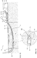
- FIG 1A a drilling rig 10 for the controlled drilling of a pilot well is shown.
- the drilling rig 10 works according to a controlled horizontal drilling process, which we also refer to as Horizontal Directional Drilling (HDD) process.
- a horizontal drilling rig available under the trade name Terra-Jet is used for this purpose.
- Such a horizontal drilling rig is for example from the document DE 101 15 233 A1 known.
- a rod 14 composed of several rod sections 13 is introduced into the ground 18 in the direction of arrow P0 with the aid of a horizontal drilling device 12 at a starting point 16 with a drill head 20 arranged on the horizontal drilling device 12 remote from the end of the rod 14.
- the horizontal drilling device 12 has a pump 42 which sucks flushing liquid 46 from a flushing liquid container 40 via a hose 48 and conveys it into the hollow rod 14 at high pressure.
- the flushing fluid 46 emerges from the drill head 20 at high pressure.
- the high pressure and the hard metal teeth of the drill head 20 cut a borehole in the ground 18.
- the drill head 20 is flattened asymmetrically at its front end and is continuously rotated with the aid of the rod 14 to produce a straight borehole. In the event of a desired lateral movement, upward movement or downward movement, the drill head 20 is stopped in a position suitable for this desired movement and is not rotated further, so that due to the asymmetrically flattened shape of the front end of the drill head 20, a corresponding deflection movement of the drill head 20 takes place in the ground 18.
- FIG. 12 is a detailed view of the end of the remote from the horizontal drilling rig 12 Linkage 14 is shown together with the drill head 20.
- An electronic probe is arranged in the drill head 20, which can be precisely located from the surface of the earth at any time with the aid of a corresponding locating device, so that the position of the drill head 20 in the earth 18 can be precisely determined at any time.
- the path of movement of the drill head 20 and thus the course of the drill channel 15 of the pilot hole is simply controlled by stopping the rotation of the drill head 20 via the rod 14 in a controlled manner, so that the control surface of the drill head 20 is brought into a position required for the desired movement. Even after the rotation of the drill head 20 has been stopped in a targeted manner, flushing fluid 46 continues to be conveyed through the rod 14 with the aid of the pump 42 and the drill head 20 is further advanced via the rod 14, so that the drilling process can be carried out with the aid of the flushing fluid 46 and the advance of the drill head 20 the desired course of the borehole is continued.
- HDPE pipes are made of high-density polyethylene, this high-density polyethylene being a thermoplastic with high density, so that the pipes made of HDPE have high toughness and rigidity, very good chemical resistance, good sliding properties, low Moisture absorption, very good processing properties, are very easy to weld and are physiologically harmless.
- tubes 26 made of other materials, in particular metal can also be drawn in.
- the horizontal drilling device 12 generates the tensile force required for the expansion process on the rod 14 and continues to guide flushing fluid 46 to the expansion head 24.
- the flushing liquid 46 at least supports the expansion of the pilot bore and also serves to drain and discharge the excess soil 18 that was loosened during the expansion process. This can take place in particular through the annular gap between the already widened area of the pilot bore, referred to as the drilling channel 15, and the drawn-in pipe 26.
- the flushing liquid 46 introduced into the annular gap also reduces the skin friction between the pipe 26 and the drilling channel 15.
- the new pipe 26 to be laid in the present case an HDPE pipe, is drawn in.
- two or more expanding tools 24 can be used one after the other with a diameter of usually up to 1000 mm.
- Pipes 26 up to a diameter of 800 mm or a pipe bundle made up of several pipes can then be drawn in.
- Water with betonite or polymers can be used as the rinsing liquid 46.
- flushing fluids 46 stabilize the drilling channel 15, reduce the friction between the drill rod 14 and the soil 18 and the friction between the pipe 26 to be pulled in and the soil 18. Furthermore, with the aid of the flushing fluid 46, soil 18 is removed from the drilling channel 15 through the pipe 26 that has already been partially pulled in promoted out.
- Figure 1D shows an enlarged section of the in Figure 1C The arrangement 10 shown.
- the end of the rod 14 remote from the horizontal drilling device 12, the expander head 24 and the pipe 26 already partially pulled into the ground 18 are shown.
- a control unit 50 of the horizontal drilling device 12 in particular a programmable logic control unit (PLC), controls the pump 42 for conveying the Rinsing fluid 46 through the linkage 14.
- PLC programmable logic control unit
- the pump 42 can be controlled by the control unit 50 in such a way that the volume flow of the flushing fluid 46 conveyed by the pump 42 and thus exiting at the drilling or expanding head 20, 24 can be controlled.
- the horizontal drilling device 12 preferably has a rotary drive for rotating the rod 14 about a longitudinal axis and the feed drive for moving the rod 14 along its longitudinal axis through the soil 18 together with the drill head 20 or expansion head 24 connected to the end of the rod 14 remote from the feed drive .
- FIG. 2 shows a perspective view of the adapter arrangement 100.
- the adapter arrangement 100 comprises a first connecting element 110, which is connected to a first rod section of the rod 14, and a second connecting element 112, which is connected to a drilling tool, such as a drilling head 20 or an expanding head 24 .
- the adapter arrangement 100 has a third connecting element 114, which can be pushed over an area with a non-cylindrical outer surface 116 of the first connecting element 110 and over an area with a non-cylindrical outer surface 118 of the second connecting element.
- the areas 116, 118 each have a hexagonal cross-section, the cross-sectional opening 120 of the third connecting element 114 having an inner cross-section that is complementary to the outer cross-sections of the areas 118, 116, so that a torque from the rod 14 to the drilling tool 20 essentially via the third connecting element 114 is transferable.
- the first connector 110 also has a section 122 with a smaller cross section than the non-cylindrical area 116, so that the third connecting element 114 can be pushed at least partially over the section 122 so that it disengages from the non-cylindrical area 118 of the second connecting element 112, to rotate this relative to the first connecting element 110.
- the third connecting element can be displaced in such a way that it at least partially encloses both non-cylindrical regions 116, 118 of the first connecting element and of the second connecting element.
- the third connecting element is also referred to as a sliding sleeve. In this state, the transmission of large torques between the rod 14 and the drilling tool 20, 24 is possible.
- the adapter arrangement 100 comprises two locking screws 124, 126, which can each be screwed through a through opening 130 in the third connecting element 114 into a hole 129 provided with an internal thread in the first connecting element 110 in order to put the third connecting element 114 in a correct position in the connected state to keep.
- a groove is also provided, into which locking pins inserted into openings 130, 131 of the third connecting element 114 engage when the elements 110, 112, 114 of the adapter arrangement 100 are connected.
- These locking pins can be provided as an alternative or in addition to the locking screws 124, 126, as will be explained in more detail below.
- the first connecting element 110 also has an area with a conical external thread 132, which can be connected to a conical internal thread in the second connecting element 112, as will be explained in more detail below.
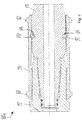
- FIG. 13 shows a sectional view of the adapter arrangement 100 according to FIG Fig. 2 in the connected state of the connecting elements 110, 112, 114.
- the external thread 132 of the first connecting element 110 is in engagement with an internal thread 134, so that a screw connection exists between the first and the second element 110, 112.
- the first connecting element 110 has a first cylindrical contact area 136 which engages with a second contact area 138 formed by a cylindrical opening in the second connecting element 112.
- first cylindrical contact area 136 there are two circumferential grooves 140, 142, in each of which a sealing element 144, 146 is arranged.
- forces acting transversely to the longitudinal axis L of the adapter arrangement 100 can be transmitted between the first connecting element 110 and the second connecting element 112 via the contact areas 136, 138.
- the first connecting element 110 comprises a third contact area 148 which engages with a further contact area 150 present in the cylindrical opening of the second connecting element 112. Forces can also be transmitted transversely to the longitudinal axis of the adapter arrangement 100 via the third contact area 148 and the fourth contact area 150.
- the securing screws 124, 126 are designed as Allen screws.
- the threaded sections 132, 134 and the contact areas 136, 138, 148, 150 are arranged and designed in such a way that no surfaces 152, 154 are in one plane are provided transversely to the longitudinal axis of the adapter arrangement 100, which contact each other in the connected state of the connecting elements 110, 112, 114 that they are pressed against one another in a slight further rotary movement of the first connecting element 110 relative to the second connecting element 112. Rather, the first and the second connecting element 110, 112 are designed and, in the connected state, arranged in such a way that a gap 155 remains between such surfaces 152, 154. This simplifies loosening the screw connection via the threaded sections 132, 134 if the connecting elements 110, 112, 114 are to be separated again.
- the first threaded section 132 is arranged between the first contact area 136 and the third contact area 148.
- the second threaded section 134 is thus arranged between the second contact area 138 and the contact area 150.
- Both the first connecting element 110 and the second connecting element 112 each have continuous cylindrical openings 156, 158 through the flushing fluid 46, which is passed through an inner through-opening of the rod 14 via the through-opening 156, 158 of the adapter arrangement 100 to the drilling tool 20, 24 .
- the third connecting element has two annular elevations 160, 162, which are arranged at a distance from one another in the direction of the longitudinal axis L of the adapter arrangement 100, and several elevations 164 to 168, which are preferably at equal angular intervals, around the third connecting element 114 whose outer surface are arranged.
- the third connecting element 114 can be actuated, in particular rotated and displaced, by an operator even in adverse environmental conditions, in particular during construction site operation, in which flushing liquid 46 adheres to the outside of the adapter arrangement 100.
- the third connecting element 114 is only secured at the same time With the help of locking screws 124, 126 and not with the help of additional locking pins.
- Figure 4 shows an adapter arrangement 100a in which the connecting elements 110, 112, 114 are arranged separately from one another, according to a second embodiment. Identical elements have the same reference symbols.
- two locking pins 170, 172 are provided, which are designed in particular as dowel pins, for example as heavy dowel pins and which are inserted into the corresponding openings 130, 131 of the third connecting element 114 after the connecting elements 110, 112, 114 have been connected to one another .
- the dowel pins 170, 172 or the heavy dowel pins 170, 172 are preferably driven into the openings 130, 131.
- the use of the pins 170, 172 in the connected state is guided by the groove 174 made in the area 116.
- the groove 174 instead of the groove 174, only a cutout can be provided in the area in which the pins 170, 172 contact the first connecting element 110.
- FIG. 11 shows a sectional illustration of the adapter arrangement 100a according to FIG Figure 4 , where the cutting plane is in Figure 4 lies in a horizontal plane.
- the connecting elements 110, 112, 114 are shown in a connected state.
- the dowel pins 170, 172 are guided through a region of the groove 174.
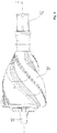
- Figure 6 shows an expansion tool 180 connected to the second connecting element 112, which instead of the expansion tool 24 according to FIGS Figures 1c and 1d can be used.
- a connection element 182 with an opening is provided, which is opposite the expansion tool 180 is freely rotatable and via which a further expansion tool and / or a pipe 26 to be introduced into the expanded opening can be connected.
- Figure 7 shows a sectional illustration of a first connecting element 110a according to a third embodiment.
- the first connecting element 110a can be used both in connection with the adapter arrangement 100 of the first embodiment and in connection with the adapter arrangement 100a of the second embodiment.
- the connecting element 110a also has a check valve 190 which is arranged in an area of the through opening 156 of the first connecting element 110a and which opens the through opening 156 only at a preset minimum rinsing fluid pressure and allows the rinsing fluid 46 to pass through the opening 156.
- Figure 8 shows a sectional view of an adapter arrangement 100b according to a fourth embodiment, the connecting elements 110b, 112, 114 being connected to one another and the connecting element 112 being formed in one piece with the drilling tool 20, 24, 180.
- channels 178 branch off, which lead through parts of the drilling tool 20, 24, 180 to outlet openings or outlet nozzles of the drilling tool 20, 24, 180.
- a check valve 190 can also be arranged in the linkage section of the linkage 14 to which the first connecting element 100, 100a, 100b is connected.
- FIG. 13 shows elements of the check valve 190 according to the third and fourth embodiment according to FIG Figures 7 and 8th in an exploded view.
- the check valve 190 comprises a guide sleeve 192, a closing ball 194, a closing spring 196 and a counterpart for mounting the closing spring 196.
- the closing spring 196 is in particular a spiral compression spring.
- FIG. 11 shows an enlarged sectional illustration of the check valve 190 according to the third embodiment according to FIG Figure 7 when closed.
- the closing ball 194 is pressed by the spring 196 against a closing cone 193 of the guide sleeve 192 so that no rinsing liquid 46 can flow out of the opening 56 of the first connecting element 100b and no dirt can penetrate through the opening 156 into the linkage 14.
- the spring 196 and the ball 194 are dimensioned such that the ball 194 is pressed away from the sealing cone 143 against the spring force of the spring 196 against a second cone 199, which is provided in the counterpart 198, when the minimum flushing pressure is provided.
- the fact that the ball 194 rests on the cone 199 prevents the ball 194 from swinging when the check valve 190 is open.
- Figure 12 shows a sectional exploded view of the elements of the check valve 190.
- the guide sleeve 192 has several guide ribs 200, 202, in particular four, five or six longitudinal ribs for guiding the movement of the closing ball 194 from the closed to the open state and from the open to the closed State has.
- the guide ribs 200, 202 are arranged at equal intervals around the longitudinal axis L and run parallel to the longitudinal axis L.
- rinsing fluid channels 204 to 208 are provided between the guide ribs 200, 202 through which the rinsing fluid 46 is arranged between the guide ribs 200, 202 Closing ball 194 in the open state by the check valve 190 and through the rinsing fluid channels 204 to 208 further into rinsing fluid channels 210 to 218 in the counterpart 198, so that the rinsing fluid 46 reaches the second connecting element 112 and from there to the drilling tool 20, 24, 180.
- first element 100, 100a, 100b can also be connected to the drilling tool 20, 24, 180 and the second element 114 can be connected to the rod 14.
Landscapes
- Engineering & Computer Science (AREA)
- Life Sciences & Earth Sciences (AREA)
- Geology (AREA)
- Mining & Mineral Resources (AREA)
- Mechanical Engineering (AREA)
- Physics & Mathematics (AREA)
- Environmental & Geological Engineering (AREA)
- Fluid Mechanics (AREA)
- General Life Sciences & Earth Sciences (AREA)
- Geochemistry & Mineralogy (AREA)
- Earth Drilling (AREA)
Claims (14)
- Ensemble adaptateur destiné à relier un outil de forage à un train de tiges de forage, ledit ensemble comprenant
un premier élément (110) qui comporte une première extrémité qui peut être ou est reliée au train de tiges de forage (14) ou à l'outil de forage (20, 24, 180), une première portion filetée (132) pourvue d'un filetage extérieur et une portion (116) de section transversale non circulaire, le premier élément (110) comportant une première zone de contact cylindrique (136) adjacente à la première portion filetée (132) ou à distance de la première portion filetée (132),
un deuxième élément (112) qui comporte une deuxième extrémité, qui peut être ou est reliée à l'outil de forage (20, 24, 180), et une deuxième portion filetée (134) complémentaire de la première portion filetée (132) et pourvue d'un filetage intérieur (134) et une portion (118) de section transversale non circulaire, et qui est approprié pour réaliser une liaison avec le premier élément (110), le deuxième élément (112) comportant une deuxième zone de contact (138) adjacente à la deuxième portion filetée (134) ou disposée à distance de la deuxième portion filetée (134) et conçue comme un évidement cylindrique,
le premier élément (110) et le deuxième élément (112) pouvant être reliés l'un à l'autre de telle sorte que le filetage de la première portion filetée (132) et le filetage de la deuxième portion filetée (134) s'engrènent l'un avec l'autre,
un troisième élément (114) qui est conçu et peut être disposé de façon à enfermer, lorsque les premier et deuxième éléments (110, 112) sont reliés, une zone (116, 118) respectivement du premier et du deuxième élément (110, 112) de section transversale non circulaire et à s'engager avec ces zones (116, 118),
la première zone de contact (136) et la deuxième zone de contact (138) étant conçues de façon à s'engager l'une avec l'autre lorsque le premier élément (110) et le deuxième élément (112) sont reliés,
le premier élément (110) et le deuxième élément (112) comportant chacun une ouverture (156, 158) qui, lorsque le premier et le deuxième élément (110, 112) sont reliés, forme de la première extrémité à la deuxième extrémité une ouverture traversante par laquelle un fluide (46) peut être conduit du train de tiges de forage (14) à l'outil de forage (20, 24, 18), et
la première zone de contact (136) comportant au moins une rainure circonférentielle (140, 142) et un élément d'étanchéité (144, 146) étant inséré dans la rainure (140, 142), caractérisé en ce que
un clapet anti-retour (190) est disposé dans l'ouverture traversante (156, 158) du premier élément (110) ou du deuxième élément (112) et permet au fluide (46) de s'écouler uniquement de la tige de forage (14) à l'outil de forage (20, 24, 180). - Ensemble adaptateur selon la revendication 1, caractérisé en ce que la première zone de contact (136) et la deuxième zone de contact (138) sont conçues de manière à s'engager l'une avec l'autre, lorsque le premier élément (110) et le deuxième élément (112) sont reliés, de telle sorte que, lorsqu'une force agit transversalement à l'axe longitudinal (L) du train de tiges (14), une force soit transmise transversalement à l'axe longitudinal (L) entre la première zone de contact (136) et la deuxième zone de contact (138).
- Ensemble adaptateur selon la revendication 1 ou 2, caractérisé en ce que la première portion filetée (132) est disposée entre la première zone de contact (136) et une troisième zone de contact cylindrique (148), en ce que la deuxième portion filetée (134) est disposée entre la deuxième zone de contact (138) et une quatrième zone de contact (150) formée dans un autre évidement cylindrique, la troisième zone de contact (148) et la quatrième zone de contact (150) étant conçues de manière à s'engager l'une avec l'autre lorsque le premier élément (110) et le deuxième élément (112) sont reliés l'un à l'autre.
- Ensemble adaptateur selon la revendication 3, caractérisé en ce que la troisième zone de contact (148) et la quatrième zone de contact (150) sont conçues de manière à s'engager l'une avec l'autre lorsque le premier élément (110) et le deuxième élément (112) sont reliés l'un à l'autre, en ce que, lorsqu'une force agit transversalement à l'axe longitudinal (L) du train de tiges (14), une force est transmise transversalement à l'axe longitudinal (L) entre la troisième zone de contact (148) et la quatrième zone de contact (150).
- Ensemble adaptateur selon l'une des revendications précédentes, caractérisé en ce que la première zone de contact (136) et la deuxième zone de contact (138) forment un ajustement, notamment un ajustement serré, un ajustement avec jeu ou un ajustement de transition, et/ou en ce que la troisième zone de contact (148) et la quatrième zone de contact (150) forment un ajustement, en particulier un ajustement serré, un ajustement avec jeu ou un ajustement de transition.
- Ensemble adaptateur selon l'une des revendications précédentes, caractérisé en ce que le diamètre de la première zone de contact (136) est inférieur au diamètre de la deuxième zone de contact (138) d'une valeur dans la gamme allant de 6/100 mm à 8/100 mm, et/ou en ce que
le diamètre de la troisième zone de contact (148) est inférieur au diamètre de la quatrième zone de contact (150) d'une valeur dans la gamme allant de 6/100 mm à 8/100 mm. - Ensemble adaptateur selon l'une des revendications précédentes, caractérisé en ce que l'élément d'étanchéité (144, 146) est inséré dans la rainure circonférentielle (140, 142) de telle sorte qu'une partie de l'élément d'étanchéité (144, 146) fait saillie circonférentiellement de la rainure (140, 142).
- Ensemble adaptateur selon l'une des revendications précédentes, caractérisé en ce que l'élément d'étanchéité (144, 146) est déformable élastiquement.
- Ensemble adaptateur selon l'une des revendications précédentes, caractérisé en ce que la première zone de contact (136) comporte au moins une deuxième rainure circonférentielle (142) dans laquelle est inséré un deuxième élément d'étanchéité (146).
- Ensemble adaptateur selon l'une des revendications précédentes, caractérisé en ce que le premier élément (110) et le deuxième élément (112) comportent chacun dans la zone (116, 118) de section non circulaire un polygone extérieur ou une dentelure extérieure, de préférence un hexagone extérieur, et en ce que le troisième élément (114) comporte une ouverture (120) qui est complémentaire des zones (116, 118) de section transversale non circulaire du premier élément (110) et du deuxième élément (112), et qui est conçu notamment comme un polygone intérieur ou une dentelure intérieure, de préférence un hexagone intérieur.
- Ensemble adaptateur selon l'une des revendications précédentes, caractérisé en ce que le troisième élément (114) est conçu comme un manchon coulissant et peut être relié, à l'état relié de préférence avec au moins une vis de blocage (124, 126) et/ou au moins un goujon de blocage (170, 172), en particulier au moins un goujon de serrage ou un goujon de serrage lourd, au premier et/ou deuxième élément (110, 112), le goujon de blocage s'engageant dans une ouverture, de préférence dans une rainure circonférentielle (174), ménagée dans le premier élément (110) ou dans le deuxième élément (112) .
- Ensemble adaptateur selon l'une des revendications précédentes, caractérisé en ce que le filetage intérieur (134) et le filetage extérieur (132) sont tous les deux des filetages coniques, notamment des filetages NPT (National Pipe Thread), des filetages Whitworth ou des filetages coniques métriques.
- Ensemble adaptateur selon l'une des revendications précédentes, caractérisé en ce que le clapet anti-retour (190) comprend un élément de fermeture (194), un élément élastiquement déformable (196) et un cône d'étanchéité (193), l'élément élastiquement déformable (196) pressant l'élément de fermeture (194) contre le cône d'étanchéité (193) lorsque le clapet anti-retour (190) est fermé et/ou l'élément élastiquement déformable étant disposé et conçu de telle sorte que, lorsque le clapet anti-retour (190) est ouvert, l'élément de fermeture (194) puisse être pressé contre un deuxième cône (199) par un flux de fluide (46) s'écoulant à travers le clapet anti-retour (190).
- Ensemble adaptateur selon la revendication 13, caractérisé en ce que l'élément de fermeture est une bille (194) et l'élément élastiquement déformable est un ressort (196) ou un bloc d'élastomère.
Priority Applications (1)
| Application Number | Priority Date | Filing Date | Title |
|---|---|---|---|
| PL19209324T PL3660260T3 (pl) | 2018-11-28 | 2019-11-15 | Układ adaptera do łączenia narzędzia wiertniczego z przewodem wiertniczym |
Applications Claiming Priority (1)
| Application Number | Priority Date | Filing Date | Title |
|---|---|---|---|
| DE102018130065.4A DE102018130065A1 (de) | 2018-11-28 | 2018-11-28 | Adapteranordnung zum Verbinden eines Bohrwerkzeugs mit einem Bohrgestänge |
Publications (2)
| Publication Number | Publication Date |
|---|---|
| EP3660260A1 EP3660260A1 (fr) | 2020-06-03 |
| EP3660260B1 true EP3660260B1 (fr) | 2021-09-15 |
Family
ID=68583114
Family Applications (1)
| Application Number | Title | Priority Date | Filing Date |
|---|---|---|---|
| EP19209324.3A Active EP3660260B1 (fr) | 2018-11-28 | 2019-11-15 | Agencement d'adaptateur permettant de raccorder un outil de forage à une tige de forage |
Country Status (3)
| Country | Link |
|---|---|
| EP (1) | EP3660260B1 (fr) |
| DE (1) | DE102018130065A1 (fr) |
| PL (1) | PL3660260T3 (fr) |
Family Cites Families (7)
| Publication number | Priority date | Publication date | Assignee | Title |
|---|---|---|---|---|
| DE19901001C2 (de) | 1999-01-13 | 2002-09-12 | Terra Ag Fuer Tiefbautechnik S | Erdbohranlage mit Gestängewechsler |
| DE10115233C5 (de) | 2000-05-11 | 2011-09-15 | TERRA AG für Tiefbautechnik | Horizontalbohranlage |
| US6845820B1 (en) * | 2000-10-19 | 2005-01-25 | Weatherford/Lamb, Inc. | Completion apparatus and methods for use in hydrocarbon wells |
| DE102010004287A1 (de) | 2010-01-11 | 2011-07-14 | TERRA AG für Tiefbautechnik | Verfahren und Anordnung zum Herstellen und/oder Aufweiten einer Erdbohrung |
| US8991490B2 (en) * | 2010-12-01 | 2015-03-31 | Vermeer Manufacturing Company | Tapered thread configuration with improved durability |
| DE102015107194A1 (de) | 2015-05-08 | 2016-11-10 | TERRA AG für Tiefbautechnik | Bohranlage zum Erzeugen oder Aufweiten einer Erdbohrung im Erdreich und Verfahren zur Steuerung eines Vorschubantriebs einer solchen Bohranlage |
| US10167680B2 (en) * | 2015-09-10 | 2019-01-01 | Hunting Energy Services, Inc. | Multi-lead quick connect threaded connection |
-
2018
- 2018-11-28 DE DE102018130065.4A patent/DE102018130065A1/de not_active Withdrawn
-
2019
- 2019-11-15 EP EP19209324.3A patent/EP3660260B1/fr active Active
- 2019-11-15 PL PL19209324T patent/PL3660260T3/pl unknown
Also Published As
| Publication number | Publication date |
|---|---|
| PL3660260T3 (pl) | 2022-01-17 |
| EP3660260A1 (fr) | 2020-06-03 |
| DE102018130065A1 (de) | 2020-05-28 |
Similar Documents
| Publication | Publication Date | Title |
|---|---|---|
| DE60023504T2 (de) | Schraubverbindung für rohre | |
| AT391009B (de) | Rohrverbindung | |
| DE3882953T2 (de) | Rammbohrgerät mit Kontrollventil. | |
| EP0397874A1 (fr) | Dispositif pour obturer une zone de complications dans un puits | |
| EP2085566A2 (fr) | Installation de forage | |
| DE3415627A1 (de) | Rohrpruefgeraet | |
| DE3923579A1 (de) | Anschlussarmatur fuer rohre, insbesondere fuer kunststoffrohre | |
| DE19803304C2 (de) | Bohrgestänge zum Drehschlagbohren, insbesondere zum Überlagerungsbohren | |
| DE19749007C2 (de) | Vorrichtung zum Verbinden eines Nachziehrohres mit einem Ziehgerät | |
| EP4067716B1 (fr) | Dispositif de montage de section de tube | |
| EP3660260B1 (fr) | Agencement d'adaptateur permettant de raccorder un outil de forage à une tige de forage | |
| DE102014204598A1 (de) | Zweistahlschraube mit Fließpressverbindung | |
| WO2009092659A2 (fr) | Tête d'injection | |
| EP4403740B1 (fr) | Raccord fileté | |
| EP3480419B1 (fr) | Dispositif formant tarière hélicoïdale et procédé de formation d'un dispositif formant tarière hélicoïdale | |
| EP2420646A1 (fr) | Raccord de tuyauterie | |
| DE10065533B4 (de) | Gestängekupplung für Gestängeschüsse mit einem Medienkanal | |
| DE19629459C2 (de) | Anbohrarmatur für Kunststoffrohre | |
| EP0310601A1 (fr) | Dispositif pour raccorder un manometre sur une canalisation. | |
| DE19747250C1 (de) | Verbindungsstück zum Einziehen von Rohrleitungen | |
| DE19918530A1 (de) | Verfahren und Kupplung zur Verbindung zweier Abschnitte eines Bohrgestänges | |
| DE10123058A1 (de) | Erdbohrvorrichtung | |
| DE102020005980A1 (de) | Steuerbarer Bohrkopf | |
| DE3207183C1 (de) | Rohrverbindung für Metallrohre | |
| DE102005045050A1 (de) | Rohreinzugsadapter mit Dichtkissen |
Legal Events
| Date | Code | Title | Description |
|---|---|---|---|
| PUAI | Public reference made under article 153(3) epc to a published international application that has entered the european phase |
Free format text: ORIGINAL CODE: 0009012 |
|
| STAA | Information on the status of an ep patent application or granted ep patent |
Free format text: STATUS: THE APPLICATION HAS BEEN PUBLISHED |
|
| AK | Designated contracting states |
Kind code of ref document: A1 Designated state(s): AL AT BE BG CH CY CZ DE DK EE ES FI FR GB GR HR HU IE IS IT LI LT LU LV MC MK MT NL NO PL PT RO RS SE SI SK SM TR |
|
| AX | Request for extension of the european patent |
Extension state: BA ME |
|
| STAA | Information on the status of an ep patent application or granted ep patent |
Free format text: STATUS: REQUEST FOR EXAMINATION WAS MADE |
|
| 17P | Request for examination filed |
Effective date: 20201124 |
|
| RBV | Designated contracting states (corrected) |
Designated state(s): AL AT BE BG CH CY CZ DE DK EE ES FI FR GB GR HR HU IE IS IT LI LT LU LV MC MK MT NL NO PL PT RO RS SE SI SK SM TR |
|
| GRAP | Despatch of communication of intention to grant a patent |
Free format text: ORIGINAL CODE: EPIDOSNIGR1 |
|
| STAA | Information on the status of an ep patent application or granted ep patent |
Free format text: STATUS: GRANT OF PATENT IS INTENDED |
|
| INTG | Intention to grant announced |
Effective date: 20210412 |
|
| GRAS | Grant fee paid |
Free format text: ORIGINAL CODE: EPIDOSNIGR3 |
|
| GRAA | (expected) grant |
Free format text: ORIGINAL CODE: 0009210 |
|
| STAA | Information on the status of an ep patent application or granted ep patent |
Free format text: STATUS: THE PATENT HAS BEEN GRANTED |
|
| AK | Designated contracting states |
Kind code of ref document: B1 Designated state(s): AL AT BE BG CH CY CZ DE DK EE ES FI FR GB GR HR HU IE IS IT LI LT LU LV MC MK MT NL NO PL PT RO RS SE SI SK SM TR |
|
| REG | Reference to a national code |
Ref country code: CH Ref legal event code: EP |
|
| REG | Reference to a national code |
Ref country code: DE Ref legal event code: R096 Ref document number: 502019002293 Country of ref document: DE |
|
| REG | Reference to a national code |
Ref country code: IE Ref legal event code: FG4D Free format text: LANGUAGE OF EP DOCUMENT: GERMAN Ref country code: NL Ref legal event code: FP |
|
| REG | Reference to a national code |
Ref country code: AT Ref legal event code: REF Ref document number: 1430661 Country of ref document: AT Kind code of ref document: T Effective date: 20211015 |
|
| REG | Reference to a national code |
Ref country code: LT Ref legal event code: MG9D |
|
| PG25 | Lapsed in a contracting state [announced via postgrant information from national office to epo] |
Ref country code: SE Free format text: LAPSE BECAUSE OF FAILURE TO SUBMIT A TRANSLATION OF THE DESCRIPTION OR TO PAY THE FEE WITHIN THE PRESCRIBED TIME-LIMIT Effective date: 20210915 Ref country code: RS Free format text: LAPSE BECAUSE OF FAILURE TO SUBMIT A TRANSLATION OF THE DESCRIPTION OR TO PAY THE FEE WITHIN THE PRESCRIBED TIME-LIMIT Effective date: 20210915 Ref country code: BG Free format text: LAPSE BECAUSE OF FAILURE TO SUBMIT A TRANSLATION OF THE DESCRIPTION OR TO PAY THE FEE WITHIN THE PRESCRIBED TIME-LIMIT Effective date: 20211215 Ref country code: LT Free format text: LAPSE BECAUSE OF FAILURE TO SUBMIT A TRANSLATION OF THE DESCRIPTION OR TO PAY THE FEE WITHIN THE PRESCRIBED TIME-LIMIT Effective date: 20210915 Ref country code: FI Free format text: LAPSE BECAUSE OF FAILURE TO SUBMIT A TRANSLATION OF THE DESCRIPTION OR TO PAY THE FEE WITHIN THE PRESCRIBED TIME-LIMIT Effective date: 20210915 Ref country code: HR Free format text: LAPSE BECAUSE OF FAILURE TO SUBMIT A TRANSLATION OF THE DESCRIPTION OR TO PAY THE FEE WITHIN THE PRESCRIBED TIME-LIMIT Effective date: 20210915 Ref country code: NO Free format text: LAPSE BECAUSE OF FAILURE TO SUBMIT A TRANSLATION OF THE DESCRIPTION OR TO PAY THE FEE WITHIN THE PRESCRIBED TIME-LIMIT Effective date: 20211215 |
|
| PG25 | Lapsed in a contracting state [announced via postgrant information from national office to epo] |
Ref country code: LV Free format text: LAPSE BECAUSE OF FAILURE TO SUBMIT A TRANSLATION OF THE DESCRIPTION OR TO PAY THE FEE WITHIN THE PRESCRIBED TIME-LIMIT Effective date: 20210915 Ref country code: GR Free format text: LAPSE BECAUSE OF FAILURE TO SUBMIT A TRANSLATION OF THE DESCRIPTION OR TO PAY THE FEE WITHIN THE PRESCRIBED TIME-LIMIT Effective date: 20211216 |
|
| PG25 | Lapsed in a contracting state [announced via postgrant information from national office to epo] |
Ref country code: IS Free format text: LAPSE BECAUSE OF FAILURE TO SUBMIT A TRANSLATION OF THE DESCRIPTION OR TO PAY THE FEE WITHIN THE PRESCRIBED TIME-LIMIT Effective date: 20220115 Ref country code: SM Free format text: LAPSE BECAUSE OF FAILURE TO SUBMIT A TRANSLATION OF THE DESCRIPTION OR TO PAY THE FEE WITHIN THE PRESCRIBED TIME-LIMIT Effective date: 20210915 Ref country code: SK Free format text: LAPSE BECAUSE OF FAILURE TO SUBMIT A TRANSLATION OF THE DESCRIPTION OR TO PAY THE FEE WITHIN THE PRESCRIBED TIME-LIMIT Effective date: 20210915 Ref country code: RO Free format text: LAPSE BECAUSE OF FAILURE TO SUBMIT A TRANSLATION OF THE DESCRIPTION OR TO PAY THE FEE WITHIN THE PRESCRIBED TIME-LIMIT Effective date: 20210915 Ref country code: PT Free format text: LAPSE BECAUSE OF FAILURE TO SUBMIT A TRANSLATION OF THE DESCRIPTION OR TO PAY THE FEE WITHIN THE PRESCRIBED TIME-LIMIT Effective date: 20220117 Ref country code: ES Free format text: LAPSE BECAUSE OF FAILURE TO SUBMIT A TRANSLATION OF THE DESCRIPTION OR TO PAY THE FEE WITHIN THE PRESCRIBED TIME-LIMIT Effective date: 20210915 Ref country code: EE Free format text: LAPSE BECAUSE OF FAILURE TO SUBMIT A TRANSLATION OF THE DESCRIPTION OR TO PAY THE FEE WITHIN THE PRESCRIBED TIME-LIMIT Effective date: 20210915 Ref country code: CZ Free format text: LAPSE BECAUSE OF FAILURE TO SUBMIT A TRANSLATION OF THE DESCRIPTION OR TO PAY THE FEE WITHIN THE PRESCRIBED TIME-LIMIT Effective date: 20210915 Ref country code: AL Free format text: LAPSE BECAUSE OF FAILURE TO SUBMIT A TRANSLATION OF THE DESCRIPTION OR TO PAY THE FEE WITHIN THE PRESCRIBED TIME-LIMIT Effective date: 20210915 |
|
| REG | Reference to a national code |
Ref country code: DE Ref legal event code: R097 Ref document number: 502019002293 Country of ref document: DE |
|
| PG25 | Lapsed in a contracting state [announced via postgrant information from national office to epo] |
Ref country code: MC Free format text: LAPSE BECAUSE OF FAILURE TO SUBMIT A TRANSLATION OF THE DESCRIPTION OR TO PAY THE FEE WITHIN THE PRESCRIBED TIME-LIMIT Effective date: 20210915 |
|
| PLBE | No opposition filed within time limit |
Free format text: ORIGINAL CODE: 0009261 |
|
| STAA | Information on the status of an ep patent application or granted ep patent |
Free format text: STATUS: NO OPPOSITION FILED WITHIN TIME LIMIT |
|
| PG25 | Lapsed in a contracting state [announced via postgrant information from national office to epo] |
Ref country code: LU Free format text: LAPSE BECAUSE OF NON-PAYMENT OF DUE FEES Effective date: 20211115 Ref country code: DK Free format text: LAPSE BECAUSE OF FAILURE TO SUBMIT A TRANSLATION OF THE DESCRIPTION OR TO PAY THE FEE WITHIN THE PRESCRIBED TIME-LIMIT Effective date: 20210915 Ref country code: BE Free format text: LAPSE BECAUSE OF NON-PAYMENT OF DUE FEES Effective date: 20211130 |
|
| REG | Reference to a national code |
Ref country code: BE Ref legal event code: MM Effective date: 20211130 |
|
| 26N | No opposition filed |
Effective date: 20220616 |
|
| PG25 | Lapsed in a contracting state [announced via postgrant information from national office to epo] |
Ref country code: SI Free format text: LAPSE BECAUSE OF FAILURE TO SUBMIT A TRANSLATION OF THE DESCRIPTION OR TO PAY THE FEE WITHIN THE PRESCRIBED TIME-LIMIT Effective date: 20210915 |
|
| PG25 | Lapsed in a contracting state [announced via postgrant information from national office to epo] |
Ref country code: IE Free format text: LAPSE BECAUSE OF NON-PAYMENT OF DUE FEES Effective date: 20211115 |
|
| PG25 | Lapsed in a contracting state [announced via postgrant information from national office to epo] |
Ref country code: IT Free format text: LAPSE BECAUSE OF FAILURE TO SUBMIT A TRANSLATION OF THE DESCRIPTION OR TO PAY THE FEE WITHIN THE PRESCRIBED TIME-LIMIT Effective date: 20210915 |
|
| PG25 | Lapsed in a contracting state [announced via postgrant information from national office to epo] |
Ref country code: CY Free format text: LAPSE BECAUSE OF FAILURE TO SUBMIT A TRANSLATION OF THE DESCRIPTION OR TO PAY THE FEE WITHIN THE PRESCRIBED TIME-LIMIT Effective date: 20210915 |
|
| PG25 | Lapsed in a contracting state [announced via postgrant information from national office to epo] |
Ref country code: HU Free format text: LAPSE BECAUSE OF FAILURE TO SUBMIT A TRANSLATION OF THE DESCRIPTION OR TO PAY THE FEE WITHIN THE PRESCRIBED TIME-LIMIT; INVALID AB INITIO Effective date: 20191115 |
|
| PG25 | Lapsed in a contracting state [announced via postgrant information from national office to epo] |
Ref country code: MK Free format text: LAPSE BECAUSE OF FAILURE TO SUBMIT A TRANSLATION OF THE DESCRIPTION OR TO PAY THE FEE WITHIN THE PRESCRIBED TIME-LIMIT Effective date: 20210915 |
|
| PG25 | Lapsed in a contracting state [announced via postgrant information from national office to epo] |
Ref country code: TR Free format text: LAPSE BECAUSE OF FAILURE TO SUBMIT A TRANSLATION OF THE DESCRIPTION OR TO PAY THE FEE WITHIN THE PRESCRIBED TIME-LIMIT Effective date: 20210915 |
|
| PG25 | Lapsed in a contracting state [announced via postgrant information from national office to epo] |
Ref country code: MT Free format text: LAPSE BECAUSE OF FAILURE TO SUBMIT A TRANSLATION OF THE DESCRIPTION OR TO PAY THE FEE WITHIN THE PRESCRIBED TIME-LIMIT Effective date: 20210915 |
|
| REG | Reference to a national code |
Ref country code: CH Ref legal event code: U11 Free format text: ST27 STATUS EVENT CODE: U-0-0-U10-U11 (AS PROVIDED BY THE NATIONAL OFFICE) Effective date: 20251201 |
|
| PGFP | Annual fee paid to national office [announced via postgrant information from national office to epo] |
Ref country code: NL Payment date: 20251119 Year of fee payment: 7 |
|
| PGFP | Annual fee paid to national office [announced via postgrant information from national office to epo] |
Ref country code: DE Payment date: 20251127 Year of fee payment: 7 |
|
| PGFP | Annual fee paid to national office [announced via postgrant information from national office to epo] |
Ref country code: GB Payment date: 20251120 Year of fee payment: 7 |
|
| PG25 | Lapsed in a contracting state [announced via postgrant information from national office to epo] |
Ref country code: AT Free format text: LAPSE BECAUSE OF NON-PAYMENT OF DUE FEES Effective date: 20241115 |
|
| PGFP | Annual fee paid to national office [announced via postgrant information from national office to epo] |
Ref country code: FR Payment date: 20251120 Year of fee payment: 7 |
|
| REG | Reference to a national code |
Ref country code: AT Ref legal event code: MM01 Ref document number: 1430661 Country of ref document: AT Kind code of ref document: T Effective date: 20241115 |
|
| PGFP | Annual fee paid to national office [announced via postgrant information from national office to epo] |
Ref country code: CH Payment date: 20251201 Year of fee payment: 7 |
|
| PGFP | Annual fee paid to national office [announced via postgrant information from national office to epo] |
Ref country code: PL Payment date: 20251014 Year of fee payment: 7 |
|
| PGFP | Annual fee paid to national office [announced via postgrant information from national office to epo] |
Ref country code: AT Payment date: 20260410 Year of fee payment: 5 |