EP3660792A2 - Interface utilisateur médicale - Google Patents
Interface utilisateur médicale Download PDFInfo
- Publication number
- EP3660792A2 EP3660792A2 EP19208480.4A EP19208480A EP3660792A2 EP 3660792 A2 EP3660792 A2 EP 3660792A2 EP 19208480 A EP19208480 A EP 19208480A EP 3660792 A2 EP3660792 A2 EP 3660792A2
- Authority
- EP
- European Patent Office
- Prior art keywords
- view
- user interface
- graphical representation
- anatomical structure
- interface screen
- Prior art date
- Legal status (The legal status is an assumption and is not a legal conclusion. Google has not performed a legal analysis and makes no representation as to the accuracy of the status listed.)
- Pending
Links
Images


Classifications
-
- G—PHYSICS
- G06—COMPUTING OR CALCULATING; COUNTING
- G06T—IMAGE DATA PROCESSING OR GENERATION, IN GENERAL
- G06T19/00—Manipulating three-dimensional [3D] models or images for computer graphics
- G06T19/20—Editing of three-dimensional [3D] images, e.g. changing shapes or colours, aligning objects or positioning parts
-
- G—PHYSICS
- G06—COMPUTING OR CALCULATING; COUNTING
- G06T—IMAGE DATA PROCESSING OR GENERATION, IN GENERAL
- G06T17/00—Three-dimensional [3D] modelling for computer graphics
-
- G—PHYSICS
- G06—COMPUTING OR CALCULATING; COUNTING
- G06T—IMAGE DATA PROCESSING OR GENERATION, IN GENERAL
- G06T19/00—Manipulating three-dimensional [3D] models or images for computer graphics
-
- A—HUMAN NECESSITIES
- A61—MEDICAL OR VETERINARY SCIENCE; HYGIENE
- A61B—DIAGNOSIS; SURGERY; IDENTIFICATION
- A61B18/00—Surgical instruments, devices or methods for transferring non-mechanical forms of energy to or from the body
- A61B18/04—Surgical instruments, devices or methods for transferring non-mechanical forms of energy to or from the body by heating
- A61B18/12—Surgical instruments, devices or methods for transferring non-mechanical forms of energy to or from the body by heating by passing a current through the tissue to be heated, e.g. high-frequency current
- A61B18/14—Probes or electrodes therefor
- A61B18/1492—Probes or electrodes therefor having a flexible, catheter-like structure, e.g. for heart ablation
-
- A—HUMAN NECESSITIES
- A61—MEDICAL OR VETERINARY SCIENCE; HYGIENE
- A61B—DIAGNOSIS; SURGERY; IDENTIFICATION
- A61B34/00—Computer-aided surgery; Manipulators or robots specially adapted for use in surgery
- A61B34/10—Computer-aided planning, simulation or modelling of surgical operations
-
- A—HUMAN NECESSITIES
- A61—MEDICAL OR VETERINARY SCIENCE; HYGIENE
- A61B—DIAGNOSIS; SURGERY; IDENTIFICATION
- A61B34/00—Computer-aided surgery; Manipulators or robots specially adapted for use in surgery
- A61B34/20—Surgical navigation systems; Devices for tracking or guiding surgical instruments, e.g. for frameless stereotaxis
-
- A—HUMAN NECESSITIES
- A61—MEDICAL OR VETERINARY SCIENCE; HYGIENE
- A61B—DIAGNOSIS; SURGERY; IDENTIFICATION
- A61B34/00—Computer-aided surgery; Manipulators or robots specially adapted for use in surgery
- A61B34/25—User interfaces for surgical systems
-
- A—HUMAN NECESSITIES
- A61—MEDICAL OR VETERINARY SCIENCE; HYGIENE
- A61B—DIAGNOSIS; SURGERY; IDENTIFICATION
- A61B5/00—Measuring for diagnostic purposes; Identification of persons
- A61B5/24—Detecting, measuring or recording bioelectric or biomagnetic signals of the body or parts thereof
- A61B5/25—Bioelectric electrodes therefor
- A61B5/279—Bioelectric electrodes therefor specially adapted for particular uses
- A61B5/28—Bioelectric electrodes therefor specially adapted for particular uses for electrocardiography [ECG]
- A61B5/283—Invasive
-
- A—HUMAN NECESSITIES
- A61—MEDICAL OR VETERINARY SCIENCE; HYGIENE
- A61B—DIAGNOSIS; SURGERY; IDENTIFICATION
- A61B5/00—Measuring for diagnostic purposes; Identification of persons
- A61B5/24—Detecting, measuring or recording bioelectric or biomagnetic signals of the body or parts thereof
- A61B5/316—Modalities, i.e. specific diagnostic methods
- A61B5/318—Heart-related electrical modalities, e.g. electrocardiography [ECG]
-
- A—HUMAN NECESSITIES
- A61—MEDICAL OR VETERINARY SCIENCE; HYGIENE
- A61B—DIAGNOSIS; SURGERY; IDENTIFICATION
- A61B5/00—Measuring for diagnostic purposes; Identification of persons
- A61B5/74—Details of notification to user or communication with user or patient; User input means
- A61B5/742—Details of notification to user or communication with user or patient; User input means using visual displays
- A61B5/743—Displaying an image simultaneously with additional graphical information, e.g. symbols, charts, function plots
-
- A—HUMAN NECESSITIES
- A61—MEDICAL OR VETERINARY SCIENCE; HYGIENE
- A61B—DIAGNOSIS; SURGERY; IDENTIFICATION
- A61B5/00—Measuring for diagnostic purposes; Identification of persons
- A61B5/74—Details of notification to user or communication with user or patient; User input means
- A61B5/742—Details of notification to user or communication with user or patient; User input means using visual displays
- A61B5/7435—Displaying user selection data, e.g. icons in a graphical user interface
-
- A—HUMAN NECESSITIES
- A61—MEDICAL OR VETERINARY SCIENCE; HYGIENE
- A61B—DIAGNOSIS; SURGERY; IDENTIFICATION
- A61B5/00—Measuring for diagnostic purposes; Identification of persons
- A61B5/74—Details of notification to user or communication with user or patient; User input means
- A61B5/7475—User input or interface means, e.g. keyboard, pointing device, joystick
-
- A—HUMAN NECESSITIES
- A61—MEDICAL OR VETERINARY SCIENCE; HYGIENE
- A61B—DIAGNOSIS; SURGERY; IDENTIFICATION
- A61B90/00—Instruments, implements or accessories specially adapted for surgery or diagnosis and not covered by any of the groups A61B1/00 - A61B50/00, e.g. for luxation treatment or for protecting wound edges
- A61B90/36—Image-producing devices or illumination devices not otherwise provided for
- A61B90/37—Surgical systems with images on a monitor during operation
-
- G—PHYSICS
- G06—COMPUTING OR CALCULATING; COUNTING
- G06F—ELECTRIC DIGITAL DATA PROCESSING
- G06F3/00—Input arrangements for transferring data to be processed into a form capable of being handled by the computer; Output arrangements for transferring data from processing unit to output unit, e.g. interface arrangements
- G06F3/01—Input arrangements or combined input and output arrangements for interaction between user and computer
- G06F3/048—Interaction techniques based on graphical user interfaces [GUI]
- G06F3/0481—Interaction techniques based on graphical user interfaces [GUI] based on specific properties of the displayed interaction object or a metaphor-based environment, e.g. interaction with desktop elements like windows or icons, or assisted by a cursor's changing behaviour or appearance
- G06F3/04815—Interaction with a metaphor-based environment or interaction object displayed as three-dimensional [3D], e.g. changing the user viewpoint with respect to the environment or object
-
- G—PHYSICS
- G06—COMPUTING OR CALCULATING; COUNTING
- G06F—ELECTRIC DIGITAL DATA PROCESSING
- G06F3/00—Input arrangements for transferring data to be processed into a form capable of being handled by the computer; Output arrangements for transferring data from processing unit to output unit, e.g. interface arrangements
- G06F3/01—Input arrangements or combined input and output arrangements for interaction between user and computer
- G06F3/048—Interaction techniques based on graphical user interfaces [GUI]
- G06F3/0481—Interaction techniques based on graphical user interfaces [GUI] based on specific properties of the displayed interaction object or a metaphor-based environment, e.g. interaction with desktop elements like windows or icons, or assisted by a cursor's changing behaviour or appearance
- G06F3/0482—Interaction with lists of selectable items, e.g. menus
-
- G—PHYSICS
- G06—COMPUTING OR CALCULATING; COUNTING
- G06F—ELECTRIC DIGITAL DATA PROCESSING
- G06F3/00—Input arrangements for transferring data to be processed into a form capable of being handled by the computer; Output arrangements for transferring data from processing unit to output unit, e.g. interface arrangements
- G06F3/01—Input arrangements or combined input and output arrangements for interaction between user and computer
- G06F3/048—Interaction techniques based on graphical user interfaces [GUI]
- G06F3/0484—Interaction techniques based on graphical user interfaces [GUI] for the control of specific functions or operations, e.g. selecting or manipulating an object, an image or a displayed text element, setting a parameter value or selecting a range
- G06F3/04845—Interaction techniques based on graphical user interfaces [GUI] for the control of specific functions or operations, e.g. selecting or manipulating an object, an image or a displayed text element, setting a parameter value or selecting a range for image manipulation, e.g. dragging, rotation, expansion or change of colour
-
- G—PHYSICS
- G06—COMPUTING OR CALCULATING; COUNTING
- G06T—IMAGE DATA PROCESSING OR GENERATION, IN GENERAL
- G06T7/00—Image analysis
- G06T7/0002—Inspection of images, e.g. flaw detection
- G06T7/0012—Biomedical image inspection
-
- G—PHYSICS
- G06—COMPUTING OR CALCULATING; COUNTING
- G06T—IMAGE DATA PROCESSING OR GENERATION, IN GENERAL
- G06T7/00—Image analysis
- G06T7/10—Segmentation; Edge detection
- G06T7/13—Edge detection
-
- G—PHYSICS
- G06—COMPUTING OR CALCULATING; COUNTING
- G06V—IMAGE OR VIDEO RECOGNITION OR UNDERSTANDING
- G06V10/00—Arrangements for image or video recognition or understanding
- G06V10/20—Image preprocessing
- G06V10/24—Aligning, centring, orientation detection or correction of the image
-
- G—PHYSICS
- G16—INFORMATION AND COMMUNICATION TECHNOLOGY [ICT] SPECIALLY ADAPTED FOR SPECIFIC APPLICATION FIELDS
- G16H—HEALTHCARE INFORMATICS, i.e. INFORMATION AND COMMUNICATION TECHNOLOGY [ICT] SPECIALLY ADAPTED FOR THE HANDLING OR PROCESSING OF MEDICAL OR HEALTHCARE DATA
- G16H20/00—ICT specially adapted for therapies or health-improving plans, e.g. for handling prescriptions, for steering therapy or for monitoring patient compliance
- G16H20/40—ICT specially adapted for therapies or health-improving plans, e.g. for handling prescriptions, for steering therapy or for monitoring patient compliance relating to mechanical, radiation or invasive therapies, e.g. surgery, laser therapy, dialysis or acupuncture
-
- G—PHYSICS
- G16—INFORMATION AND COMMUNICATION TECHNOLOGY [ICT] SPECIALLY ADAPTED FOR SPECIFIC APPLICATION FIELDS
- G16H—HEALTHCARE INFORMATICS, i.e. INFORMATION AND COMMUNICATION TECHNOLOGY [ICT] SPECIALLY ADAPTED FOR THE HANDLING OR PROCESSING OF MEDICAL OR HEALTHCARE DATA
- G16H30/00—ICT specially adapted for the handling or processing of medical images
- G16H30/20—ICT specially adapted for the handling or processing of medical images for handling medical images, e.g. DICOM, HL7 or PACS
-
- G—PHYSICS
- G16—INFORMATION AND COMMUNICATION TECHNOLOGY [ICT] SPECIALLY ADAPTED FOR SPECIFIC APPLICATION FIELDS
- G16H—HEALTHCARE INFORMATICS, i.e. INFORMATION AND COMMUNICATION TECHNOLOGY [ICT] SPECIALLY ADAPTED FOR THE HANDLING OR PROCESSING OF MEDICAL OR HEALTHCARE DATA
- G16H30/00—ICT specially adapted for the handling or processing of medical images
- G16H30/40—ICT specially adapted for the handling or processing of medical images for processing medical images, e.g. editing
-
- A—HUMAN NECESSITIES
- A61—MEDICAL OR VETERINARY SCIENCE; HYGIENE
- A61B—DIAGNOSIS; SURGERY; IDENTIFICATION
- A61B17/00—Surgical instruments, devices or methods
- A61B17/00234—Surgical instruments, devices or methods for minimally invasive surgery
- A61B2017/00238—Type of minimally invasive operation
- A61B2017/00243—Type of minimally invasive operation cardiac
-
- A—HUMAN NECESSITIES
- A61—MEDICAL OR VETERINARY SCIENCE; HYGIENE
- A61B—DIAGNOSIS; SURGERY; IDENTIFICATION
- A61B18/00—Surgical instruments, devices or methods for transferring non-mechanical forms of energy to or from the body
- A61B2018/00315—Surgical instruments, devices or methods for transferring non-mechanical forms of energy to or from the body for treatment of particular body parts
- A61B2018/00345—Vascular system
- A61B2018/00351—Heart
-
- A—HUMAN NECESSITIES
- A61—MEDICAL OR VETERINARY SCIENCE; HYGIENE
- A61B—DIAGNOSIS; SURGERY; IDENTIFICATION
- A61B18/00—Surgical instruments, devices or methods for transferring non-mechanical forms of energy to or from the body
- A61B2018/00571—Surgical instruments, devices or methods for transferring non-mechanical forms of energy to or from the body for achieving a particular surgical effect
- A61B2018/00577—Ablation
-
- A—HUMAN NECESSITIES
- A61—MEDICAL OR VETERINARY SCIENCE; HYGIENE
- A61B—DIAGNOSIS; SURGERY; IDENTIFICATION
- A61B18/00—Surgical instruments, devices or methods for transferring non-mechanical forms of energy to or from the body
- A61B2018/00636—Sensing and controlling the application of energy
- A61B2018/00773—Sensed parameters
- A61B2018/00839—Bioelectrical parameters, e.g. ECG, EEG
-
- A—HUMAN NECESSITIES
- A61—MEDICAL OR VETERINARY SCIENCE; HYGIENE
- A61B—DIAGNOSIS; SURGERY; IDENTIFICATION
- A61B34/00—Computer-aided surgery; Manipulators or robots specially adapted for use in surgery
- A61B34/10—Computer-aided planning, simulation or modelling of surgical operations
- A61B2034/101—Computer-aided simulation of surgical operations
- A61B2034/105—Modelling of the patient, e.g. for ligaments or bones
-
- A—HUMAN NECESSITIES
- A61—MEDICAL OR VETERINARY SCIENCE; HYGIENE
- A61B—DIAGNOSIS; SURGERY; IDENTIFICATION
- A61B34/00—Computer-aided surgery; Manipulators or robots specially adapted for use in surgery
- A61B34/10—Computer-aided planning, simulation or modelling of surgical operations
- A61B2034/107—Visualisation of planned trajectories or target regions
-
- A—HUMAN NECESSITIES
- A61—MEDICAL OR VETERINARY SCIENCE; HYGIENE
- A61B—DIAGNOSIS; SURGERY; IDENTIFICATION
- A61B34/00—Computer-aided surgery; Manipulators or robots specially adapted for use in surgery
- A61B34/20—Surgical navigation systems; Devices for tracking or guiding surgical instruments, e.g. for frameless stereotaxis
- A61B2034/2046—Tracking techniques
- A61B2034/2051—Electromagnetic tracking systems
- A61B2034/2053—Tracking an applied voltage gradient
-
- A—HUMAN NECESSITIES
- A61—MEDICAL OR VETERINARY SCIENCE; HYGIENE
- A61B—DIAGNOSIS; SURGERY; IDENTIFICATION
- A61B34/00—Computer-aided surgery; Manipulators or robots specially adapted for use in surgery
- A61B34/20—Surgical navigation systems; Devices for tracking or guiding surgical instruments, e.g. for frameless stereotaxis
- A61B2034/2046—Tracking techniques
- A61B2034/2065—Tracking using image or pattern recognition
-
- A—HUMAN NECESSITIES
- A61—MEDICAL OR VETERINARY SCIENCE; HYGIENE
- A61B—DIAGNOSIS; SURGERY; IDENTIFICATION
- A61B34/00—Computer-aided surgery; Manipulators or robots specially adapted for use in surgery
- A61B34/20—Surgical navigation systems; Devices for tracking or guiding surgical instruments, e.g. for frameless stereotaxis
- A61B2034/2072—Reference field transducer attached to an instrument or patient
-
- A—HUMAN NECESSITIES
- A61—MEDICAL OR VETERINARY SCIENCE; HYGIENE
- A61B—DIAGNOSIS; SURGERY; IDENTIFICATION
- A61B34/00—Computer-aided surgery; Manipulators or robots specially adapted for use in surgery
- A61B34/25—User interfaces for surgical systems
- A61B2034/252—User interfaces for surgical systems indicating steps of a surgical procedure
-
- A—HUMAN NECESSITIES
- A61—MEDICAL OR VETERINARY SCIENCE; HYGIENE
- A61B—DIAGNOSIS; SURGERY; IDENTIFICATION
- A61B34/00—Computer-aided surgery; Manipulators or robots specially adapted for use in surgery
- A61B34/25—User interfaces for surgical systems
- A61B2034/254—User interfaces for surgical systems being adapted depending on the stage of the surgical procedure
-
- A—HUMAN NECESSITIES
- A61—MEDICAL OR VETERINARY SCIENCE; HYGIENE
- A61B—DIAGNOSIS; SURGERY; IDENTIFICATION
- A61B90/00—Instruments, implements or accessories specially adapted for surgery or diagnosis and not covered by any of the groups A61B1/00 - A61B50/00, e.g. for luxation treatment or for protecting wound edges
- A61B90/36—Image-producing devices or illumination devices not otherwise provided for
- A61B2090/364—Correlation of different images or relation of image positions in respect to the body
- A61B2090/367—Correlation of different images or relation of image positions in respect to the body creating a 3D dataset from 2D images using position information
-
- A—HUMAN NECESSITIES
- A61—MEDICAL OR VETERINARY SCIENCE; HYGIENE
- A61B—DIAGNOSIS; SURGERY; IDENTIFICATION
- A61B90/00—Instruments, implements or accessories specially adapted for surgery or diagnosis and not covered by any of the groups A61B1/00 - A61B50/00, e.g. for luxation treatment or for protecting wound edges
- A61B90/36—Image-producing devices or illumination devices not otherwise provided for
- A61B2090/364—Correlation of different images or relation of image positions in respect to the body
- A61B2090/368—Correlation of different images or relation of image positions in respect to the body changing the image on a display according to the operator's position
-
- A—HUMAN NECESSITIES
- A61—MEDICAL OR VETERINARY SCIENCE; HYGIENE
- A61B—DIAGNOSIS; SURGERY; IDENTIFICATION
- A61B2560/00—Constructional details of operational features of apparatus; Accessories for medical measuring apparatus
- A61B2560/02—Operational features
- A61B2560/0295—Operational features adapted for recording user messages or annotations
-
- A—HUMAN NECESSITIES
- A61—MEDICAL OR VETERINARY SCIENCE; HYGIENE
- A61B—DIAGNOSIS; SURGERY; IDENTIFICATION
- A61B5/00—Measuring for diagnostic purposes; Identification of persons
- A61B5/05—Detecting, measuring or recording for diagnosis by means of electric currents or magnetic fields; Measuring using microwaves or radio waves
- A61B5/055—Detecting, measuring or recording for diagnosis by means of electric currents or magnetic fields; Measuring using microwaves or radio waves involving electronic [EMR] or nuclear [NMR] magnetic resonance, e.g. magnetic resonance imaging
-
- A—HUMAN NECESSITIES
- A61—MEDICAL OR VETERINARY SCIENCE; HYGIENE
- A61B—DIAGNOSIS; SURGERY; IDENTIFICATION
- A61B5/00—Measuring for diagnostic purposes; Identification of persons
- A61B5/06—Devices, other than using radiation, for detecting or locating foreign bodies ; Determining position of diagnostic devices within or on the body of the patient
- A61B5/065—Determining position of the probe employing exclusively positioning means located on or in the probe, e.g. using position sensors arranged on the probe
-
- A—HUMAN NECESSITIES
- A61—MEDICAL OR VETERINARY SCIENCE; HYGIENE
- A61M—DEVICES FOR INTRODUCING MEDIA INTO, OR ONTO, THE BODY; DEVICES FOR TRANSDUCING BODY MEDIA OR FOR TAKING MEDIA FROM THE BODY; DEVICES FOR PRODUCING OR ENDING SLEEP OR STUPOR
- A61M25/00—Catheters; Hollow probes
- A61M25/01—Introducing, guiding, advancing, emplacing or holding catheters
- A61M25/0105—Steering means as part of the catheter or advancing means; Markers for positioning
- A61M2025/0166—Sensors, electrodes or the like for guiding the catheter to a target zone, e.g. image guided or magnetically guided
-
- G—PHYSICS
- G06—COMPUTING OR CALCULATING; COUNTING
- G06T—IMAGE DATA PROCESSING OR GENERATION, IN GENERAL
- G06T2207/00—Indexing scheme for image analysis or image enhancement
- G06T2207/10—Image acquisition modality
- G06T2207/10072—Tomographic images
- G06T2207/10081—Computed x-ray tomography [CT]
-
- G—PHYSICS
- G06—COMPUTING OR CALCULATING; COUNTING
- G06T—IMAGE DATA PROCESSING OR GENERATION, IN GENERAL
- G06T2207/00—Indexing scheme for image analysis or image enhancement
- G06T2207/10—Image acquisition modality
- G06T2207/10072—Tomographic images
- G06T2207/10088—Magnetic resonance imaging [MRI]
- G06T2207/10096—Dynamic contrast-enhanced magnetic resonance imaging [DCE-MRI]
-
- G—PHYSICS
- G06—COMPUTING OR CALCULATING; COUNTING
- G06T—IMAGE DATA PROCESSING OR GENERATION, IN GENERAL
- G06T2207/00—Indexing scheme for image analysis or image enhancement
- G06T2207/30—Subject of image; Context of image processing
- G06T2207/30004—Biomedical image processing
- G06T2207/30048—Heart; Cardiac
-
- G—PHYSICS
- G06—COMPUTING OR CALCULATING; COUNTING
- G06T—IMAGE DATA PROCESSING OR GENERATION, IN GENERAL
- G06T2210/00—Indexing scheme for image generation or computer graphics
- G06T2210/41—Medical
-
- G—PHYSICS
- G06—COMPUTING OR CALCULATING; COUNTING
- G06T—IMAGE DATA PROCESSING OR GENERATION, IN GENERAL
- G06T2219/00—Indexing scheme for manipulating 3D models or images for computer graphics
- G06T2219/004—Annotating, labelling
-
- G—PHYSICS
- G06—COMPUTING OR CALCULATING; COUNTING
- G06T—IMAGE DATA PROCESSING OR GENERATION, IN GENERAL
- G06T2219/00—Indexing scheme for manipulating 3D models or images for computer graphics
- G06T2219/20—Indexing scheme for editing of 3D models
- G06T2219/2016—Rotation, translation, scaling
-
- G—PHYSICS
- G06—COMPUTING OR CALCULATING; COUNTING
- G06V—IMAGE OR VIDEO RECOGNITION OR UNDERSTANDING
- G06V2201/00—Indexing scheme relating to image or video recognition or understanding
- G06V2201/03—Recognition of patterns in medical or anatomical images
- G06V2201/032—Recognition of patterns in medical or anatomical images of protuberances, polyps nodules, etc.
Definitions
- the present invention relates to a medical user interface, and in particular, to display of an image of a 3D anatomical structure in a medical user interface.
- Medical images of various body parts may be formed in numerous ways for example but not limited to, X-ray radiography, magnetic resonance imaging (MRI), medical ultrasonography or ultrasound, endoscopy, elastography, tactile imaging, thermography, medical photography and nuclear medicine functional imaging techniques.
- MRI magnetic resonance imaging
- elastography tactile imaging
- thermography thermography
- medical photography nuclear medicine functional imaging techniques.
- CT and MRI scans produced two-dimensional (2D) static output on film.
- 2D two-dimensional
- US Patent Publication 2010/0316268 of Liang, et al. describes a procedure for pre-operating assessment of one or more anatomical structures generated from medical images and provided in a rendered 3D space, and an imaging system, apparatus, and computer program, that operate in accordance with the procedure.
- the procedure comprises providing one or more safety margin indicators in the rendered 3D space, each having a shape corresponding to that of a respective one of the anatomical structures within an organ and having a predetermined size of safety margin from the respective one of the anatomical structures.
- the procedure also comprises manipulating at least one of the shape and predetermined size of safety margin of at least one of the safety margin indicators in the rendered 3D space, and immediately providing a rendering in the 3D space of a manipulated version of the at least one safety margin indicator. Also provided is a procedure for defining at least one cutting surface to resect one or more medical anatomical structures using an imaging system.
- US Patent Publication 2009/0028403 of Bar-Aviv, et al. describes a system for analyzing a source medical image of a body organ.
- the system comprises an input unit for obtaining the source medical image having three dimensions or more, a feature extraction unit that is designed for obtaining a number of features of the body organ from the source medical image, and a classification unit that is designed for estimating a priority level according to the features.
- US Patent Publication 2003/0152897 of Geiger describes a method for navigating a viewpoint of a virtual endoscope in a lumen of a structure.
- the method includes the steps of determining an initial viewpoint of the virtual endoscope, the initial viewpoint having a first center point and first direction, determining a longest ray from the initial viewpoint to the lumen, the longest ray having a first longest ray direction, determining a second direction between the first direction of the initial viewpoint and the first longest ray direction, turning the viewpoint to the second direction and moving the initial viewpoint a first predetermined distance in a first direction of the initial viewpoint, calculating a second center point of the viewpoint, moving the viewpoint to the second center point.
- a system including a medical device configured to form a three-dimensional (3D) image of an anatomical structure in a body of a living subject, a user interface including a display and an input device, and a processor configured to prepare a user interface screen presentation including a graphical representation of the anatomical structure based on the 3D image, generate a feature list of a plurality of features associated with the anatomical structure, each of the features having a respective location, render the user interface screen presentation to the display showing a first view of the graphical representation of the anatomical structure, while showing the first view, receive an input from the user interface selecting a feature from the list, and render the user interface screen presentation to the display showing the graphical representation of the anatomical structure being automatically rotated from the first view to a second view showing the selected feature at the respective location on the graphical representation.
- 3D three-dimensional
- the processor is configured to render the user interface screen presentation on the display showing the graphical representation of the anatomical structure being automatically rotated and automatically translated from the first view to the second view.
- the processor is configured to render the user interface screen presentation on the display showing the graphical representation of the anatomical structure being automatically rotated and automatically translated from the first view to the second view so as to center the selected feature in a panel of the user interface screen presentation.
- the processor is configured to render the user interface screen presentation on the display showing the graphical representation of the anatomical structure being automatically rotated from the first view to the second view and automatically zoomed in at the second view to enlarge the selected feature.
- the processor is configured to generate at least part of the feature list from medical readings performed by the medical device with respect to at least some of the plurality of features.
- the medical readings include any one or more of the following a location of a catheter, at least one location of at least one electrode of the catheter, a location where an Electrocardiogram (ECG) had been performed, a location where an ablation has been performed, or a location where the ablation is planned to be performed.
- ECG Electrocardiogram
- the system includes a probe including the plurality of electrodes and being configured to perform the ablation.
- the processor is configured to receive an input from the user interface indicating addition of an annotation to the graphical representation at a respective location, the processor being configured to add the annotation to the feature list.
- the annotation forms a perimeter of a shape.
- the processor is configured to render the user interface screen presentation on the display showing the graphical representation of the anatomical structure being automatically rotated and automatically translated from the first view to the second view so as to center the annotation based on a centroid of the shape of the annotation.
- a method including receiving a three-dimensional (3D) image of an anatomical structure in a body of a living subject, preparing a user interface screen presentation including a graphical representation of the anatomical structure based on the 3D image, generating a feature list of a plurality of features associated with the anatomical structure, each of the features having a respective location, rendering the user interface screen presentation to a display showing a first view of the graphical representation of the anatomical structure, while showing the first view, receiving an input from a user interface selecting a feature from the list, and rendering the user interface screen presentation to the display showing the graphical representation of the anatomical structure being automatically rotated from the first view to a second view showing the selected feature at the respective location on the graphical representation.
- 3D three-dimensional
- the method includes rendering the user interface screen presentation on the display showing the graphical representation of the anatomical structure being automatically rotated and automatically translated from the first view to the second view.
- the method includes rendering the user interface screen presentation on the display showing the graphical representation of the anatomical structure being automatically rotated and automatically translated from the first view to the second view so as to center the selected feature in a panel of the user interface screen presentation.
- the method includes rendering the user interface screen presentation on the display showing the graphical representation of the anatomical structure being automatically rotated from the first view to the second view and automatically zoomed in at the second view to enlarge the selected feature.
- the generating includes generating at least part of the feature list from medical readings performed by a medical device with respect to at least some of the plurality of features.
- the medical readings include any one or more of the following a location of a catheter, at least one location of at least one electrode of the catheter, a location where an Electrocardiogram (ECG) had been performed, a location where an ablation has been performed, or a location where the ablation is planned to be performed.
- ECG Electrocardiogram
- the method includes performing the ablation.
- the method includes receiving an input from the user interface indicating addition of an annotation to the graphical representation at a respective location, and adding the annotation to the feature list.
- annotation forms a perimeter of a shape.
- the method includes rendering the user interface screen presentation on the display showing the graphical representation of the anatomical structure being automatically rotated and automatically translated from the first view to the second view so as to center the annotation based on a centroid of the shape of the annotation.
- a system including a user interface including a display and an input device, and a processor configured to prepare a user interface screen presentation including a graphical representation of an anatomical structure based on a three-dimensional (3D) image of the anatomical structure in a body of a living subject, generate a feature list of a plurality of features associated with the anatomical structure, each of the features having a respective location, render the user interface screen presentation to the display showing a first view of the graphical representation of the anatomical structure, while showing the first view, receive an input from the user interface selecting a feature from the list, and render the user interface screen presentation to the display showing the graphical representation of the anatomical structure being automatically rotated from the first view to a second view showing the selected feature at the respective location on the graphical representation.
- 3D three-dimensional
- the processor is configured to render the user interface screen presentation on the display showing the graphical representation of the anatomical structure being automatically rotated and automatically translated from the first view to the second view.
- the processor is configured to render the user interface screen presentation on the display showing the graphical representation of the anatomical structure being automatically rotated and automatically translated from the first view to the second view so as to center the selected feature in a panel of the user interface screen presentation.
- the processor is configured to render the user interface screen presentation on the display showing the graphical representation of the anatomical structure being automatically rotated from the first view to the second view and automatically zoomed in at the second view to enlarge the selected feature.
- the processor is configured to generate at least part of the feature list from medical readings performed by a medical device with respect to at least some of the plurality of features.
- the medical readings include any one or more of the following a location of a catheter, at least one location of at least one electrode of the catheter, a location where an Electrocardiogram (ECG) had been performed, a location where an ablation has been performed, or a location where the ablation is planned to be performed.
- ECG Electrocardiogram
- the processor is configured to receive an input from the user interface indicating addition of an annotation to the graphical representation at a respective location, the processor being configured to add the annotation to the feature list.
- annotation forms a perimeter of a shape.
- the processor is configured to render the user interface screen presentation on the display showing the graphical representation of the anatomical structure being automatically rotated and automatically translated from the first view to the second view so as to center the annotation based on a centroid of the shape of the annotation.
- a software product including a non-transient computer-readable medium in which program instructions are stored, which instructions, when read by a central processing unit (CPU), cause the CPU to prepare a user interface screen presentation including a graphical representation of an anatomical structure based on a three-dimensional (3D) image of the anatomical structure in a body of a living subject, generate a feature list of a plurality of features associated with the anatomical structure, each of the features having a respective location, render the user interface screen presentation to a display showing a first view of the graphical representation of the anatomical structure, while showing the first view, receive an input from a user interface selecting a feature from the list, and render the user interface screen presentation to the display showing the graphical representation of the anatomical structure being automatically rotated from the first view to a second view showing the selected feature at the respective location on the graphical representation.
- CPU central processing unit
- Embodiments of the present invention provide a system including a user interface screen presentation which allows a user to select features of an anatomical structure from a list of features (or feature list) even though the selected feature may not currently be in view.
- a graphical representation of the anatomical structure is automatically rotated by the system until the selected feature is shown to the user on the screen.
- the system shows the anatomical structure being rotated until the selected feature is shown. In the above manner, even features hidden from view may be found both quickly and accurately thereby reducing the human error factor.
- the system also automatically translates (shifts) the graphical representation to display the selected feature in a more optimal fashion, for example, but not limited to, in the center of a display panel on the screen. In order for the user to see the context of the position of the selected feature, the system shows the anatomical structure being translated (shifted) on the screen.
- the system may also zoom-in to the selected feature so that the selected feature may be viewed with greater ease and in order for the user to see the context of the position of the selected feature.
- the system can thus show the anatomical structure being enlarged on the screen.
- the graphical representation of the anatomical structure is generally derived from a 3D image of the anatomical structure which is formed by a medical device.
- the medical device may take medical readings described in more detail below.
- Such a medical device may comprise a non-invasive device, such as a CT or MRI scanner, for example, or an invasive device, such as a catheter that is inserted into and maps the anatomical structure.
- 3D image encompasses all such types of 3D data, including, without limitation, 3D scans and 3D maps of anatomical structures.
- the feature list includes features associated with the anatomical structure with each feature having a respective location with respect to the graphical representation of the anatomical structure.
- the features may be generated automatically and/or manually.
- Automatic generation of the feature list may be performed by the system based on medical readings of the medical device, for example, but not limited to, a location of a catheter, a location(s) of an electrode(s) of the catheter, a location where an Electrocardiogram (ECG) had been performed, a location where an ablation has been performed, or a location where the ablation is planned to be performed.
- the feature list may include a general description of the feature, e.g., catheter location X, ablation point Y, or planned ablation Z.
- the feature list may also include more detailed information, for example, but not limited to, detailed position coordinates, electrical readings, ablation timings or temperatures.
- the feature list may be generated by the user adding annotations to the graphical representation at various respective locations on the graphical representation of the anatomical structure.
- the annotations may comprise icons, shapes or even free-form annotations.
- the user may add suitable descriptive text to each annotation which is added to the feature list to enable easy user selection of the added annotation.
- Fig. 1 is a partly pictorial, partly block diagram view of a medical imaging system 10 constructed and operative in accordance with an embodiment of the present invention.
- the medical imaging system 10 includes a medical device to form a three-dimensional (3D) image of an anatomical structure in a body of a living subject.
- the anatomical structure may be any suitable anatomical structure, for example, but not limited to a limb or part thereof, an internal organ or any other suitable body part.
- a heart 12 is shown as the anatomical structure used to illustrate some embodiments of the present invention.
- the 3D image of the anatomical structure is used as input to a user interface screen presentation, which is described in more detail with reference to Figs. 2-11 .
- the 3D image may be formed using the system and method described herein below with reference to Fig. 1 where the 3D image of the anatomical structure (e.g., the heart 12) may be formed using mapping techniques based on positions of a probe 14. Additionally, or alternatively, the 3D scan may be formed using any suitable medical imaging method including ultrasound, Magnetic Resonance Imaging (MRI), or computed tomography (CT) scans by way of example only.
- MRI Magnetic Resonance Imaging
- CT computed tomography
- the system 10 comprises the probe 14, such as a catheter, which is percutaneously inserted by an operator 16 through the patient's vascular system into a chamber or vascular structure of the heart 12.
- the operator 16 who is typically a physician, brings a distal tip 18 of the probe 14 into contact with the heart wall, for example, at an ablation target site to perform an ablation or to capture electrical potentials over time at multiple sample locations over a surface of one or more chambers of the heart 12 or to capture positions of the surface of the heart 12 in order to generate the 3D image of the heart.
- Electrical activation maps may be prepared, according to the methods disclosed in U.S. Patent Nos. 6,226,542 , and 6,301,496 , and in commonly assigned U.S. Patent No.
- Areas determined to be abnormal can be ablated by application of thermal energy, e.g., by passage of radiofrequency electrical current through wires in the probe 14 to one or more electrodes at the distal tip 18, which apply the radiofrequency energy to the myocardium.
- the energy is absorbed in the tissue, heating it to a temperature (typically about 50°C) at which it permanently loses its electrical excitability.
- this procedure creates non-conducting lesions in the cardiac tissue, which disrupt the abnormal electrical pathway causing the arrhythmia.
- the principles of the invention can be applied to different heart chambers to diagnose and treat many different cardiac arrhythmias.
- the probe 14 typically comprises a handle 20, having suitable controls on the handle to enable the operator 16 to steer, position and orient the distal tip 18 of the probe 14 as desired for the ablation.
- a distal portion of the probe 14 contains position sensors (not shown) that provide signals to a processor 22, located in a console 24.
- the processor 22 may fulfill several processing functions as described below.
- Ablation energy and electrical signals can be conveyed to and from the heart 12 through one or more ablation electrodes 32 located at or near the distal tip 18 of the probe 14 via cable 34 to the console 24.
- the ablation electrodes 32 of the probe 14 are configured to capture electrical potentials over time at multiple sample locations over a surface of one or more chambers of the heart 12.
- other electrodes may be configured to capture electrical potentials over time at multiple sample locations over a surface of one or more chambers of the heart 12.
- Pacing signals and other control signals may be conveyed from the console 24 through the cable 34 and the electrodes 32 to the heart 12.
- Sensing electrodes 33, also connected to the console 24 are disposed between the ablation electrodes 32 and have connections to the cable 34.
- the probe 14 may be implemented without the ablation electrodes 32 as an exploratory device having electrodes configured to capture electrical potentials over time at multiple sample location over a surface of one or more chambers of the heart 12.
- Wire connections 35 link the console 24 with body surface electrodes 30 and other components of a positioning sub-system for measuring location and orientation coordinates of the probe 14.
- the processor 22 or another processor may be an element of the positioning subsystem.
- the electrodes 32 and the body surface electrodes 30 may be used to measure tissue impedance at the ablation site as taught in U.S. Patent No. 7,536,218, issued to Govari et al ., which is herein incorporated by reference.
- a sensor for bioelectric information e.g., a temperature sensor (not shown), typically a thermocouple or thermistor, may be mounted on or near each of the electrodes 32.
- the console 24 typically contains one or more ablation power generators 25.
- the probe 14 may be adapted to conduct ablative energy to the heart using any known ablation technique, e.g., radiofrequency energy, ultrasound energy, and laser-produced light energy. Such methods are disclosed in commonly assigned U.S. Patent Nos. 6,814,733 , 6,997,924 , and 7,156,816 , which are herein incorporated by reference.
- the positioning subsystem comprises a magnetic position tracking arrangement that determines the position and orientation of the probe 14 by generating magnetic fields in a predefined working volume and sensing these fields at the probe 14, using field generating coils 28.
- the positioning subsystem is described in U.S. Patent No. 7,756,576 , which is hereby incorporated by reference, and in the above-noted U.S. Patent No. 7,536,218 .
- the probe 14 is coupled to the console 24, which enables the operator 16 to observe and regulate the functions of the probe 14.
- the processor 22 may be embodied as a computer with appropriate signal processing circuits.
- the processor 22 is coupled to drive a monitor 29 including a display 37.
- the signal processing circuits typically receive, amplify, filter and digitize signals from the probe 14, including signals generated by sensors such as electrical, temperature and contact force sensors, and a plurality of location sensing electrodes (not shown) located distally in the probe 14.
- the digitized signals are received and used by the console 24 and the positioning system to compute the position and orientation of the probe 14, and to analyze the electrical signals from the electrodes.
- the processor 22 typically comprises an electroanatomic map generator, an image registration program, an image or data analysis program and a graphical user interface configured to present graphical information on the monitor 29.
- processor 22 may be combined in a single physical component or, alternatively, implemented using multiple physical components. These physical components may comprise hardwired or programmable devices, or a combination of the two. In some embodiments, at least some of the functions of the processor may be carried out by a programmable processor under the control of suitable software. This software may be downloaded to a device in electronic form, over a network, for example. Alternatively or additionally, the software may be stored in tangible, non-transitory computer-readable storage media, such as optical, magnetic, or electronic memory.
- the console 24 may also include a user interface comprising the display 37 and an input device 39 to receive input commands from the operator 16 (or other user) via any suitable user input device, for example, but not limited to, a pointing device (such as a mouse of stylus), a keyboard, and/or a touch sensitive screen implemented in the display 37.
- a user interface comprising the display 37 and an input device 39 to receive input commands from the operator 16 (or other user) via any suitable user input device, for example, but not limited to, a pointing device (such as a mouse of stylus), a keyboard, and/or a touch sensitive screen implemented in the display 37.
- the system 10 includes other elements, which are not shown in the figures for the sake of simplicity.
- the system 10 may include an electrocardiogram (ECG) monitor, coupled to receive signals from the body surface electrodes 30, in order to provide an ECG synchronization signal to the console 24.
- ECG electrocardiogram
- the system 10 typically also includes a reference position sensor, either on an externally applied reference patch attached to the exterior of the subject's body, or on an internally placed probe, which is inserted into the heart 12 maintained in a fixed position relative to the heart 12. Conventional pumps and lines for circulating liquids through the probe 14 for cooling the ablation site are provided.
- the system 10 may receive image data from an external imaging modality, such as an MRI unit or the like and includes image processors that can be incorporated in or invoked by the processor 22 for generating and displaying images.
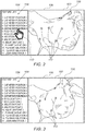
- Fig. 2 is a schematic view of a user interface screen presentation 100 for use with the medical imaging system 10 of Fig. 1 .
- the user interface screen presentation 100 includes an image panel 102 and a feature list panel 104.
- the image panel 102 includes one view of a graphical representation 106 of an anatomical structure (e.g., the heart 12 ( Fig. 1 ) or any other suitable body part).
- the graphical representation 106 is derived from a three-dimensional (3D) image of the anatomical structure formed by the medical imaging system 10 or any suitable imaging device.
- the graphical representation 106 includes a plurality of features 112 which may represent various features associated with the anatomical structure, such as a prior catheter position, a current catheter position, an ECG location, an ablation point, a planned ablation point or any other suitable feature.
- the features 112 shown in Fig. 2 have been shown as annuli (2D donut shapes).
- the features 112 may be represented by any suitable shape and/or format (e.g., color and/or shading). Different types of features 112 may be shown using different shapes and/or different formats. For the sake of simplicity all the features 112 include an identical symbol. In the figures, only some of the features 112 have been labeled for the sake of simplicity.
- the feature list panel 104 includes a feature list 108 listing the various features 112 of the anatomical structure.
- Each feature 112 has a respective location on the graphical representation 106 which may be derived from the 3D image or based on a location on the graphical representation 106 at which the feature 112 was added.
- Some of the features 112 are shown on the current view of the graphical representation 106 as shown in Fig. 2 whereas other features 112 may be currently hidden from view as the features 112 are disposed on a side of the graphical representation 106 which is not shown in Fig. 2 .
- the user interface screen presentation 100 is still showing the current view of the graphical representation 106, a user may select one of the features 112 from the feature list 108.
- FIG. 2 illustrates a cursor 110, manipulated by the user, hovering of item 5 in the feature list 108.
- the user then performs a selection action to select display of item 5 from the feature list 108.
- the processor 22 ( Fig. 1 ) is configured to receive an input from the input device 39 of the user interface selecting the feature (e.g., item 5) from the feature list 108.
- Item 5 is not included in the current view of the graphical representation 106, therefore the graphical representation 106 is rotated to show item 5 as will be described below with reference to Figs. 3-6 .
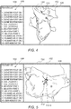
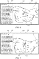
- FIGs. 3-9 are schematic views of the user interface screen presentation 100 of Fig. 2 illustrating rotation, translation, and zooming to a selected feature.
- Figs. 3-6 show the graphical representation 106 being gradually automatically rotated from the view shown in Fig. 2 to a new view shown in Fig. 6 , which includes the selected item 5, feature 112-5.
- the feature 112-5 is first shown in Fig. 5 .
- the feature 112-5 includes an annulus which is surrounded by a ring to indicate that it is the selected feature 112.
- Fig. 6 also shows squares (not labeled) that are generally disposed on lines extending outward from the annulus. The squares represent electrode positions of the catheter when the catheter was at position 5.
- the selected feature 112-5 is still not centered in the image panel 102. Therefore, in some embodiments, the processor 22 automatically translates (shifts) the graphical representation 106 (e.g., up, down, left and/or right or any suitable combination thereof) so that the selected feature 112-5 is shown in the center of the image panel 102 as shown in Fig. 7 .
- the center of the feature 112-5 may be defined by a center of the annulus of the feature 112-5 or by a centroid of a shape encompassing the annulus and the squares representing the electrode positions.
- the graphical representation 106 may also be automatically translated (shifted) (e.g., up, down, left and/or right or any suitable combination thereof) any number of times to keep whatever side of the graphical representation 106 is being shown in view and generally centrally positioned in the image panel 102.
- the user has the ability to manually rotate and translate the graphical representation 106 within the image panel 102.
- the graphical representation 106 is automatically rotated and/or translated so that a plane of the feature 112-5 is parallel with the plane of the image panel 102.
- the plane of the feature 112-5 may be defined as a plane defining average positions of the various points, for example, using a least square fit of the points of the feature 112-5.
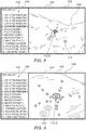
- Figs. 8-9 show the graphical representation 106 being enlarged (zoomed-in) thereby enlarging the view of the feature 112-5. If another feature 112 is selected from the feature list 108, the processor 22 is configured to zoom-out of the view of the graphical representation 106 prior to rotating the graphical representation 106 to the new view of the graphical representation 106. In some embodiments, the graphical representation 106 may not be scaled down or up.
- the rotation, translation, and scaling of the graphical representation 106 may be performed using a suitable function, for example, but not limited to, an affine transformation.
- Fig. 10 is a schematic view of the user interface screen presentation 100 of Fig. 2 illustrating addition of an annotation 112-15.
- the processor 22 ( Fig. 1 ) is configured to receive an input from the input device 39 of the user interface indicating addition of the annotation 112-15 to the graphical representation 106 at a respective location.
- the annotation 112-15 forms a perimeter of a shape.
- the shape shown in Fig. 10 is an irregular shape formed by a user drawing a line on the graphical representation 106 using a suitable pointing device such as a mouse or stylus.
- the shape may be any suitable shape including a regular shape such as a rectangle, square, ellipse, circle, or triangle, by way of example only.
- the annotation may include a symbol, graphic, and/or picture.
- the processor 22 is configured to add the annotation 112-15 to the feature list 108.
- the annotation 112-5 is added as item 15 in the feature list 108.
- the processor 22 is configured to render the user interface screen presentation 100 showing the graphical representation 106 of the anatomical structure being automatically rotated (and optionally automatically translated and/or zoomed) from a current view to another view of the graphical representation 106 so as to center the annotation 112-15 based on a centroid 114 of the shape of the annotation 112-15.
- FIG. 11 is a flow chart 200 including exemplary steps in a method of operation of the medical imaging system 10 of Fig. 1 .
- a medical device (such as one included in the medical imaging system 10) is configured to form (block 202) (e.g., by scanning or mapping data) the 3D image of the anatomical structure in the body of the living subject.
- the medical device is configured to perform medical readings (block 204) using a suitable device, for example, but not limited to, using the probe 14 ( Fig. 1 ).
- the medical readings may include any one or more of the following, by way of example only: a (current or previous) location of a catheter, at least one location of at least one electrode of the catheter, a location where an ECG had been performed, a location where an ablation has been performed, or a location where an ablation is planned to be performed.
- the processor 22 is configured to generate (block 206) the feature list 108 ( Figs. 2-10 ) of the features 112 associated with the anatomical structure. Each feature 112 has a respective location with respect to the graphical representation 106 of the anatomical structure and/or the 3D scan. In some embodiments, the processor 22 is configured to generate at least part of the feature list 108 from medical readings performed by the medical device with respect to at least some of the features 112. In some embodiments, the feature list 108 is generated based on user generated annotations described with reference to steps of blocks 218-220 below.
- the processor 22 is configured to prepare (block 208) the user interface screen presentation 100 ( Figs. 2-10 ) including the graphical representation 106 ( Figs. 2-10 ) of the anatomical structure based on the 3D image.
- the processor 22 is configured to render (block 210) the user interface screen presentation 100 to the display 37 ( Fig. 1 ) showing a first view of the graphical representation 106 of the anatomical structure. While showing the first view, the processor 22 is configured to receive (block 212) an input from the input device 39 of the user interface selecting one of the features 112 from the feature list 108.
- the processor 22 is configured to render the user interface screen presentation 100 to the display 37 showing (block 214) the graphical representation 106 of the anatomical structure being automatically rotated from the first view to a second view, which shows the selected feature 112 at the respective location on the graphical representation 106.
- the processor 22 is configured to render the user interface screen presentation 100 on the display 37 showing the graphical representation 106 of the anatomical structure being automatically rotated and automatically translated from the first view to the second view.
- the processor 22 is configured to render the user interface screen presentation 100 on the display 37 showing the graphical representation 106 of the anatomical structure being automatically rotated and automatically translated from the first view to the second view so as to center (horizontally and/or vertically) the selected feature 112 in the image panel 102 ( Figs. 2-10 ) of the user interface screen presentation 100.
- the processor 22 is configured to render the user interface screen presentation 100 on the display 37 showing the graphical representation 106 of the anatomical structure being automatically rotated (and translated) from the first view to the second view and automatically zoomed in at the second view to enlarge the selected feature 112.
- the steps of blocks 212 and 214 may be repeated (arrow 216) based on newly selected features 112 selected by the user.
- the processor 22 is configured to receive (block 218) an input from the input device 39 of the user interface indicating addition of an annotation to the graphical representation 106 at a respective location.
- the annotation forms a perimeter of a shape.
- the shape may be an irregular shape, for example, formed by a user drawing a line on the graphical representation 106 using a suitable pointing device such as a mouse or stylus.
- the shape may be any suitable shape including a regular shape such as a rectangle, square, ellipse, circle, or triangle, by way of example only.
- the annotation may include a symbol, graphic, and/or picture.
- the processor 22 is configured to add (block 220) the annotation to the feature list 108. More annotations may be added to the list by repeating (arrow 222) the steps of blocks 218-220.
- Additional features 112 may be selected by the user from the feature list 108 leading to the graphical representation 106 automatically rotating (and optionally translating and/or zooming) in the image panel 102 to the selected features 112 by repeating (arrow 224) the steps of blocks 212-214.
- One of the selected features 112 may include a user added annotation.
- the processor 22 is configured to render the user interface screen presentation 100 on the display 37 showing the graphical representation 106 of the anatomical structure being automatically rotated (and optionally automatically translated and/or automatically zoomed) from a current view to another view including the selected annotation.
- the processor 22 is configured to render the user interface screen presentation 100 on the display 37 showing the graphical representation 106 of the anatomical structure being automatically rotated and automatically translated (and optionally automatically zoomed) from a current view to another view so as to center the selected annotation based on the centroid 114 of the shape of the annotation.
Landscapes
- Engineering & Computer Science (AREA)
- Health & Medical Sciences (AREA)
- Life Sciences & Earth Sciences (AREA)
- Surgery (AREA)
- General Health & Medical Sciences (AREA)
- Medical Informatics (AREA)
- Public Health (AREA)
- Physics & Mathematics (AREA)
- Nuclear Medicine, Radiotherapy & Molecular Imaging (AREA)
- Theoretical Computer Science (AREA)
- Heart & Thoracic Surgery (AREA)
- Molecular Biology (AREA)
- Animal Behavior & Ethology (AREA)
- Biomedical Technology (AREA)
- Veterinary Medicine (AREA)
- General Engineering & Computer Science (AREA)
- General Physics & Mathematics (AREA)
- Human Computer Interaction (AREA)
- Radiology & Medical Imaging (AREA)
- Pathology (AREA)
- Robotics (AREA)
- Cardiology (AREA)
- Biophysics (AREA)
- Epidemiology (AREA)
- Primary Health Care (AREA)
- Software Systems (AREA)
- Computer Graphics (AREA)
- Plasma & Fusion (AREA)
- Otolaryngology (AREA)
- Computer Hardware Design (AREA)
- Gynecology & Obstetrics (AREA)
- Oral & Maxillofacial Surgery (AREA)
- Architecture (AREA)
- Computer Vision & Pattern Recognition (AREA)
- Urology & Nephrology (AREA)
- Multimedia (AREA)
- Geometry (AREA)
- Quality & Reliability (AREA)
- Apparatus For Radiation Diagnosis (AREA)
- Measuring And Recording Apparatus For Diagnosis (AREA)
Applications Claiming Priority (1)
| Application Number | Priority Date | Filing Date | Title |
|---|---|---|---|
| US16/188,482 US10672510B1 (en) | 2018-11-13 | 2018-11-13 | Medical user interface |
Publications (2)
| Publication Number | Publication Date |
|---|---|
| EP3660792A2 true EP3660792A2 (fr) | 2020-06-03 |
| EP3660792A3 EP3660792A3 (fr) | 2020-09-09 |
Family
ID=68583061
Family Applications (1)
| Application Number | Title | Priority Date | Filing Date |
|---|---|---|---|
| EP19208480.4A Pending EP3660792A3 (fr) | 2018-11-13 | 2019-11-12 | Interface utilisateur médicale |
Country Status (10)
| Country | Link |
|---|---|
| US (1) | US10672510B1 (fr) |
| EP (1) | EP3660792A3 (fr) |
| JP (1) | JP7460355B2 (fr) |
| KR (1) | KR20200056927A (fr) |
| CN (1) | CN111179410B (fr) |
| AU (1) | AU2019232883A1 (fr) |
| BR (1) | BR102019023073A2 (fr) |
| CA (1) | CA3057515A1 (fr) |
| IL (1) | IL269646B (fr) |
| RU (1) | RU2019136074A (fr) |
Families Citing this family (8)
| Publication number | Priority date | Publication date | Assignee | Title |
|---|---|---|---|---|
| CN109857318A (zh) * | 2018-12-26 | 2019-06-07 | 深圳开立生物医疗科技股份有限公司 | 基于超声诊断系统的超声图像处理方法、设备及存储介质 |
| EP4172956A1 (fr) * | 2020-06-29 | 2023-05-03 | Koninklijke Philips N.V. | Génération et affichage d'un rendu d'un appendice auriculaire gauche |
| US11974881B2 (en) * | 2020-08-26 | 2024-05-07 | GE Precision Healthcare LLC | Method and system for providing an anatomic orientation indicator with a patient-specific model of an anatomical structure of interest extracted from a three-dimensional ultrasound volume |
| TWI760938B (zh) * | 2020-11-25 | 2022-04-11 | 客制化科技股份有限公司 | 直覺訂製系統 |
| US12478433B2 (en) * | 2021-10-20 | 2025-11-25 | Olympus Corporation | Image guidance during cannulation |
| KR102696585B1 (ko) * | 2022-03-23 | 2024-08-20 | 오스템임플란트 주식회사 | Tmj 영상 제공 방법, 그리고 이를 구현하기 위한 장치 |
| US20230372021A1 (en) * | 2022-05-20 | 2023-11-23 | Biosense Webster (Israel) Ltd. | Displaying orthographic and endoscopic views of a plane selected in a three-dimensional anatomical image |
| CN115399807A (zh) * | 2022-08-29 | 2022-11-29 | 武汉迈瑞医疗技术研究院有限公司 | 胎儿目标部位的超声成像方法和超声成像系统 |
Citations (11)
| Publication number | Priority date | Publication date | Assignee | Title |
|---|---|---|---|---|
| US6226542B1 (en) | 1998-07-24 | 2001-05-01 | Biosense, Inc. | Three-dimensional reconstruction of intrabody organs |
| US6301496B1 (en) | 1998-07-24 | 2001-10-09 | Biosense, Inc. | Vector mapping of three-dimensionally reconstructed intrabody organs and method of display |
| US20030152897A1 (en) | 2001-12-20 | 2003-08-14 | Bernhard Geiger | Automatic navigation for virtual endoscopy |
| US6814733B2 (en) | 2002-01-31 | 2004-11-09 | Biosense, Inc. | Radio frequency pulmonary vein isolation |
| US6892091B1 (en) | 2000-02-18 | 2005-05-10 | Biosense, Inc. | Catheter, method and apparatus for generating an electrical map of a chamber of the heart |
| US6997924B2 (en) | 2002-09-17 | 2006-02-14 | Biosense Inc. | Laser pulmonary vein isolation |
| US7156816B2 (en) | 2002-11-26 | 2007-01-02 | Biosense, Inc. | Ultrasound pulmonary vein isolation |
| US20090028403A1 (en) | 2006-03-03 | 2009-01-29 | Medic Vision - Brain Technologies Ltd. | System and Method of Automatic Prioritization and Analysis of Medical Images |
| US7536218B2 (en) | 2005-07-15 | 2009-05-19 | Biosense Webster, Inc. | Hybrid magnetic-based and impedance-based position sensing |
| US7756576B2 (en) | 2005-08-26 | 2010-07-13 | Biosense Webster, Inc. | Position sensing and detection of skin impedance |
| US20100316268A1 (en) | 2009-05-12 | 2010-12-16 | Edda Technology Inc. | System, method, apparatus, and computer program for interactive pre-operative assessment |
Family Cites Families (24)
| Publication number | Priority date | Publication date | Assignee | Title |
|---|---|---|---|---|
| US6762755B2 (en) | 2000-10-16 | 2004-07-13 | Pixel Science, Inc. | Method and apparatus for creating and displaying interactive three dimensional computer images |
| EP1565888A2 (fr) * | 2002-11-29 | 2005-08-24 | Bracco Imaging S.p.A. | Systeme et procede d'affichage et de comparaison de modeles tridimensionnels (correspondance tridimensionnelle) |
| CA2610345C (fr) * | 2005-06-02 | 2013-12-24 | The Medipattern Corporation | Systeme et procede de detection assistee par ordinateur |
| US9373181B2 (en) * | 2005-10-17 | 2016-06-21 | Siemens Medical Soultions Usa, Inc. | System and method for enhanced viewing of rib metastasis |
| JP2007316993A (ja) * | 2006-05-26 | 2007-12-06 | Omron Corp | 画像処理装置、画像データを選択させる方法、およびその方法をコンピュータに実行させるためのプログラム |
| US20080117225A1 (en) * | 2006-11-21 | 2008-05-22 | Rainer Wegenkittl | System and Method for Geometric Image Annotation |
| GB0708358D0 (en) * | 2007-05-01 | 2007-06-06 | Cambridge Entpr Ltd | Strain image display systems |
| EP2175810B1 (fr) * | 2007-07-27 | 2016-03-16 | Vorum Research Corporation | Procédé, appareil, supports et signaux pour produire la représentation d'un moule |
| US20100299155A1 (en) * | 2009-05-19 | 2010-11-25 | Myca Health, Inc. | System and method for providing a multi-dimensional contextual platform for managing a medical practice |
| US9439735B2 (en) * | 2009-06-08 | 2016-09-13 | MRI Interventions, Inc. | MRI-guided interventional systems that can track and generate dynamic visualizations of flexible intrabody devices in near real time |
| US8665268B2 (en) * | 2009-09-22 | 2014-03-04 | Siemens Aktiengesellschaft | Image data and annotation processing system |
| US20110160569A1 (en) * | 2009-12-31 | 2011-06-30 | Amit Cohen | system and method for real-time surface and volume mapping of anatomical structures |
| JP5662082B2 (ja) * | 2010-08-23 | 2015-01-28 | 富士フイルム株式会社 | 画像表示装置および方法、並びに、プログラム |
| US8867802B2 (en) * | 2011-04-19 | 2014-10-21 | Microsoft Corporation | Automatic organ localization |
| JP2013017569A (ja) * | 2011-07-08 | 2013-01-31 | Shimadzu Corp | X線撮影装置 |
| US10037820B2 (en) * | 2012-05-29 | 2018-07-31 | Medical Avatar Llc | System and method for managing past, present, and future states of health using personalized 3-D anatomical models |
| US9373087B2 (en) * | 2012-10-25 | 2016-06-21 | Microsoft Technology Licensing, Llc | Decision tree training in machine learning |
| EP2996617B1 (fr) * | 2013-05-09 | 2021-04-14 | Koninklijke Philips N.V. | Commande robotique d'un endoscope à partir de caractéristiques anatomiques |
| EP3846176B1 (fr) * | 2013-09-25 | 2024-09-04 | HeartFlow, Inc. | Systèmes et procédés de validation et de correction d'annotations d'images médicales automatisées |
| KR101581785B1 (ko) * | 2015-03-05 | 2016-01-04 | 재단법인차세대융합기술연구원 | 3차원 생물학적 정보 처리 방법 및 그 시스템 |
| CN112120736B (zh) * | 2015-05-07 | 2023-04-18 | 深圳迈瑞生物医疗电子股份有限公司 | 三维超声成像方法和装置 |
| CN105662466A (zh) * | 2016-01-11 | 2016-06-15 | 深圳开立生物医疗科技股份有限公司 | 一种体位图、添加方法、控制装置及其超声设备 |
| US10788791B2 (en) * | 2016-02-22 | 2020-09-29 | Real View Imaging Ltd. | Method and system for displaying holographic images within a real object |
| US11612429B2 (en) * | 2017-05-31 | 2023-03-28 | Covidien Lp | Systems and methods for thermal ablation distortion detection |
-
2018
- 2018-11-13 US US16/188,482 patent/US10672510B1/en active Active
-
2019
- 2019-09-19 AU AU2019232883A patent/AU2019232883A1/en not_active Abandoned
- 2019-09-25 IL IL269646A patent/IL269646B/en unknown
- 2019-10-03 CA CA3057515A patent/CA3057515A1/fr not_active Abandoned
- 2019-11-01 BR BR102019023073-8A patent/BR102019023073A2/pt not_active IP Right Cessation
- 2019-11-08 KR KR1020190142545A patent/KR20200056927A/ko not_active Ceased
- 2019-11-11 RU RU2019136074A patent/RU2019136074A/ru unknown
- 2019-11-12 JP JP2019204483A patent/JP7460355B2/ja active Active
- 2019-11-12 EP EP19208480.4A patent/EP3660792A3/fr active Pending
- 2019-11-13 CN CN201911106157.1A patent/CN111179410B/zh active Active
Patent Citations (11)
| Publication number | Priority date | Publication date | Assignee | Title |
|---|---|---|---|---|
| US6226542B1 (en) | 1998-07-24 | 2001-05-01 | Biosense, Inc. | Three-dimensional reconstruction of intrabody organs |
| US6301496B1 (en) | 1998-07-24 | 2001-10-09 | Biosense, Inc. | Vector mapping of three-dimensionally reconstructed intrabody organs and method of display |
| US6892091B1 (en) | 2000-02-18 | 2005-05-10 | Biosense, Inc. | Catheter, method and apparatus for generating an electrical map of a chamber of the heart |
| US20030152897A1 (en) | 2001-12-20 | 2003-08-14 | Bernhard Geiger | Automatic navigation for virtual endoscopy |
| US6814733B2 (en) | 2002-01-31 | 2004-11-09 | Biosense, Inc. | Radio frequency pulmonary vein isolation |
| US6997924B2 (en) | 2002-09-17 | 2006-02-14 | Biosense Inc. | Laser pulmonary vein isolation |
| US7156816B2 (en) | 2002-11-26 | 2007-01-02 | Biosense, Inc. | Ultrasound pulmonary vein isolation |
| US7536218B2 (en) | 2005-07-15 | 2009-05-19 | Biosense Webster, Inc. | Hybrid magnetic-based and impedance-based position sensing |
| US7756576B2 (en) | 2005-08-26 | 2010-07-13 | Biosense Webster, Inc. | Position sensing and detection of skin impedance |
| US20090028403A1 (en) | 2006-03-03 | 2009-01-29 | Medic Vision - Brain Technologies Ltd. | System and Method of Automatic Prioritization and Analysis of Medical Images |
| US20100316268A1 (en) | 2009-05-12 | 2010-12-16 | Edda Technology Inc. | System, method, apparatus, and computer program for interactive pre-operative assessment |
Also Published As
| Publication number | Publication date |
|---|---|
| JP7460355B2 (ja) | 2024-04-02 |
| CN111179410A (zh) | 2020-05-19 |
| CA3057515A1 (fr) | 2020-05-13 |
| US10672510B1 (en) | 2020-06-02 |
| JP2020078551A (ja) | 2020-05-28 |
| AU2019232883A1 (en) | 2020-05-28 |
| IL269646B (en) | 2022-02-01 |
| RU2019136074A3 (fr) | 2021-11-01 |
| IL269646A (en) | 2020-05-31 |
| EP3660792A3 (fr) | 2020-09-09 |
| RU2019136074A (ru) | 2021-05-11 |
| CN111179410B (zh) | 2024-08-27 |
| KR20200056927A (ko) | 2020-05-25 |
| US20200152315A1 (en) | 2020-05-14 |
| BR102019023073A2 (pt) | 2020-06-02 |
Similar Documents
| Publication | Publication Date | Title |
|---|---|---|
| US10672510B1 (en) | Medical user interface | |
| EP3422297B1 (fr) | Système et procédé de visualisation d'un état de verre dans une imagerie cardiaque tridimensionnelle (3d) en temps réel | |
| EP3878354A1 (fr) | Interface utilisateur électrophysiologique | |
| US9147289B2 (en) | Method for visualizing the quality of an ablation process | |
| CN106691580B (zh) | 用于超声图像引导的消融天线放置的系统和方法 | |
| EP4299006B1 (fr) | Cartographie de fronts d'onde d'activation | |
| US20210353370A1 (en) | Catheter navigation systems and methods | |
| EP1787594A2 (fr) | Système et procédé d'ablation améliorée de tumeurs | |
| EP3970618A1 (fr) | Systèmes et procédés de visualisation de chambre cardiaque | |
| RU2735068C1 (ru) | Система и способ для визуализации на дисплее изображения частично уплощенной поверхности внутренней поверхности полости, а также постоянный машиночитаемый носитель | |
| US12564371B2 (en) | System and method for displaying ablation zone progression |
Legal Events
| Date | Code | Title | Description |
|---|---|---|---|
| PUAI | Public reference made under article 153(3) epc to a published international application that has entered the european phase |
Free format text: ORIGINAL CODE: 0009012 |
|
| STAA | Information on the status of an ep patent application or granted ep patent |
Free format text: STATUS: THE APPLICATION HAS BEEN PUBLISHED |
|
| AK | Designated contracting states |
Kind code of ref document: A2 Designated state(s): AL AT BE BG CH CY CZ DE DK EE ES FI FR GB GR HR HU IE IS IT LI LT LU LV MC MK MT NL NO PL PT RO RS SE SI SK SM TR |
|
| AX | Request for extension of the european patent |
Extension state: BA ME |
|
| PUAL | Search report despatched |
Free format text: ORIGINAL CODE: 0009013 |
|
| AK | Designated contracting states |
Kind code of ref document: A3 Designated state(s): AL AT BE BG CH CY CZ DE DK EE ES FI FR GB GR HR HU IE IS IT LI LT LU LV MC MK MT NL NO PL PT RO RS SE SI SK SM TR |
|
| AX | Request for extension of the european patent |
Extension state: BA ME |
|
| RIC1 | Information provided on ipc code assigned before grant |
Ipc: G06T 19/20 20110101AFI20200806BHEP |
|
| STAA | Information on the status of an ep patent application or granted ep patent |
Free format text: STATUS: REQUEST FOR EXAMINATION WAS MADE |
|
| 17P | Request for examination filed |
Effective date: 20210128 |
|
| RBV | Designated contracting states (corrected) |
Designated state(s): AL AT BE BG CH CY CZ DE DK EE ES FI FR GB GR HR HU IE IS IT LI LT LU LV MC MK MT NL NO PL PT RO RS SE SI SK SM TR |
|
| STAA | Information on the status of an ep patent application or granted ep patent |
Free format text: STATUS: EXAMINATION IS IN PROGRESS |
|
| 17Q | First examination report despatched |
Effective date: 20240604 |