EP3660968B1 - Brennstoffzellensystem und verfahren zur steuerung davon - Google Patents
Brennstoffzellensystem und verfahren zur steuerung davon Download PDFInfo
- Publication number
- EP3660968B1 EP3660968B1 EP17918834.7A EP17918834A EP3660968B1 EP 3660968 B1 EP3660968 B1 EP 3660968B1 EP 17918834 A EP17918834 A EP 17918834A EP 3660968 B1 EP3660968 B1 EP 3660968B1
- Authority
- EP
- European Patent Office
- Prior art keywords
- reformer
- fuel
- fuel cell
- concentration
- gas
- Prior art date
- Legal status (The legal status is an assumption and is not a legal conclusion. Google has not performed a legal analysis and makes no representation as to the accuracy of the status listed.)
- Active
Links
Images


Classifications
-
- H—ELECTRICITY
- H01—ELECTRIC ELEMENTS
- H01M—PROCESSES OR MEANS, e.g. BATTERIES, FOR THE DIRECT CONVERSION OF CHEMICAL ENERGY INTO ELECTRICAL ENERGY
- H01M8/00—Fuel cells; Manufacture thereof
- H01M8/06—Combination of fuel cells with means for production of reactants or for treatment of residues
- H01M8/0606—Combination of fuel cells with means for production of reactants or for treatment of residues with means for production of gaseous reactants
- H01M8/0612—Combination of fuel cells with means for production of reactants or for treatment of residues with means for production of gaseous reactants from carbon-containing material
- H01M8/0618—Reforming processes, e.g. autothermal, partial oxidation or steam reforming
-
- H—ELECTRICITY
- H01—ELECTRIC ELEMENTS
- H01M—PROCESSES OR MEANS, e.g. BATTERIES, FOR THE DIRECT CONVERSION OF CHEMICAL ENERGY INTO ELECTRICAL ENERGY
- H01M8/00—Fuel cells; Manufacture thereof
- H01M8/04—Auxiliary arrangements, e.g. for control of pressure or for circulation of fluids
- H01M8/04007—Auxiliary arrangements, e.g. for control of pressure or for circulation of fluids related to heat exchange
- H01M8/04014—Heat exchange using gaseous fluids; Heat exchange by combustion of reactants
- H01M8/04022—Heating by combustion
-
- H—ELECTRICITY
- H01—ELECTRIC ELEMENTS
- H01M—PROCESSES OR MEANS, e.g. BATTERIES, FOR THE DIRECT CONVERSION OF CHEMICAL ENERGY INTO ELECTRICAL ENERGY
- H01M8/00—Fuel cells; Manufacture thereof
- H01M8/04—Auxiliary arrangements, e.g. for control of pressure or for circulation of fluids
- H01M8/04007—Auxiliary arrangements, e.g. for control of pressure or for circulation of fluids related to heat exchange
- H01M8/04037—Electrical heating
-
- H—ELECTRICITY
- H01—ELECTRIC ELEMENTS
- H01M—PROCESSES OR MEANS, e.g. BATTERIES, FOR THE DIRECT CONVERSION OF CHEMICAL ENERGY INTO ELECTRICAL ENERGY
- H01M8/00—Fuel cells; Manufacture thereof
- H01M8/04—Auxiliary arrangements, e.g. for control of pressure or for circulation of fluids
- H01M8/04082—Arrangements for control of reactant parameters, e.g. pressure or concentration
- H01M8/04201—Reactant storage and supply, e.g. means for feeding, pipes
-
- H—ELECTRICITY
- H01—ELECTRIC ELEMENTS
- H01M—PROCESSES OR MEANS, e.g. BATTERIES, FOR THE DIRECT CONVERSION OF CHEMICAL ENERGY INTO ELECTRICAL ENERGY
- H01M8/00—Fuel cells; Manufacture thereof
- H01M8/04—Auxiliary arrangements, e.g. for control of pressure or for circulation of fluids
- H01M8/04298—Processes for controlling fuel cells or fuel cell systems
- H01M8/04313—Processes for controlling fuel cells or fuel cell systems characterised by the detection or assessment of variables; characterised by the detection or assessment of failure or abnormal function
- H01M8/0432—Temperature; Ambient temperature
- H01M8/04373—Temperature; Ambient temperature of auxiliary devices, e.g. reformers, compressors, burners
-
- H—ELECTRICITY
- H01—ELECTRIC ELEMENTS
- H01M—PROCESSES OR MEANS, e.g. BATTERIES, FOR THE DIRECT CONVERSION OF CHEMICAL ENERGY INTO ELECTRICAL ENERGY
- H01M8/00—Fuel cells; Manufacture thereof
- H01M8/04—Auxiliary arrangements, e.g. for control of pressure or for circulation of fluids
- H01M8/04298—Processes for controlling fuel cells or fuel cell systems
- H01M8/04313—Processes for controlling fuel cells or fuel cell systems characterised by the detection or assessment of variables; characterised by the detection or assessment of failure or abnormal function
- H01M8/0444—Concentration; Density
-
- H—ELECTRICITY
- H01—ELECTRIC ELEMENTS
- H01M—PROCESSES OR MEANS, e.g. BATTERIES, FOR THE DIRECT CONVERSION OF CHEMICAL ENERGY INTO ELECTRICAL ENERGY
- H01M8/00—Fuel cells; Manufacture thereof
- H01M8/04—Auxiliary arrangements, e.g. for control of pressure or for circulation of fluids
- H01M8/04298—Processes for controlling fuel cells or fuel cell systems
- H01M8/04313—Processes for controlling fuel cells or fuel cell systems characterised by the detection or assessment of variables; characterised by the detection or assessment of failure or abnormal function
- H01M8/04537—Electric variables
- H01M8/04544—Voltage
-
- H—ELECTRICITY
- H01—ELECTRIC ELEMENTS
- H01M—PROCESSES OR MEANS, e.g. BATTERIES, FOR THE DIRECT CONVERSION OF CHEMICAL ENERGY INTO ELECTRICAL ENERGY
- H01M8/00—Fuel cells; Manufacture thereof
- H01M8/04—Auxiliary arrangements, e.g. for control of pressure or for circulation of fluids
- H01M8/04298—Processes for controlling fuel cells or fuel cell systems
- H01M8/04313—Processes for controlling fuel cells or fuel cell systems characterised by the detection or assessment of variables; characterised by the detection or assessment of failure or abnormal function
- H01M8/04537—Electric variables
- H01M8/04574—Current
- H01M8/04582—Current of the individual fuel cell
-
- H—ELECTRICITY
- H01—ELECTRIC ELEMENTS
- H01M—PROCESSES OR MEANS, e.g. BATTERIES, FOR THE DIRECT CONVERSION OF CHEMICAL ENERGY INTO ELECTRICAL ENERGY
- H01M8/00—Fuel cells; Manufacture thereof
- H01M8/04—Auxiliary arrangements, e.g. for control of pressure or for circulation of fluids
- H01M8/04298—Processes for controlling fuel cells or fuel cell systems
- H01M8/04313—Processes for controlling fuel cells or fuel cell systems characterised by the detection or assessment of variables; characterised by the detection or assessment of failure or abnormal function
- H01M8/04537—Electric variables
- H01M8/04604—Power, energy, capacity or load
- H01M8/04611—Power, energy, capacity or load of the individual fuel cell
-
- H—ELECTRICITY
- H01—ELECTRIC ELEMENTS
- H01M—PROCESSES OR MEANS, e.g. BATTERIES, FOR THE DIRECT CONVERSION OF CHEMICAL ENERGY INTO ELECTRICAL ENERGY
- H01M8/00—Fuel cells; Manufacture thereof
- H01M8/04—Auxiliary arrangements, e.g. for control of pressure or for circulation of fluids
- H01M8/04298—Processes for controlling fuel cells or fuel cell systems
- H01M8/04694—Processes for controlling fuel cells or fuel cell systems characterised by variables to be controlled
- H01M8/04701—Temperature
- H01M8/04738—Temperature of auxiliary devices, e.g. reformer, compressor, burner
-
- H—ELECTRICITY
- H01—ELECTRIC ELEMENTS
- H01M—PROCESSES OR MEANS, e.g. BATTERIES, FOR THE DIRECT CONVERSION OF CHEMICAL ENERGY INTO ELECTRICAL ENERGY
- H01M8/00—Fuel cells; Manufacture thereof
- H01M8/04—Auxiliary arrangements, e.g. for control of pressure or for circulation of fluids
- H01M8/04298—Processes for controlling fuel cells or fuel cell systems
- H01M8/04694—Processes for controlling fuel cells or fuel cell systems characterised by variables to be controlled
- H01M8/04746—Pressure; Flow
- H01M8/04776—Pressure; Flow at auxiliary devices, e.g. reformer, compressor, burner
-
- Y—GENERAL TAGGING OF NEW TECHNOLOGICAL DEVELOPMENTS; GENERAL TAGGING OF CROSS-SECTIONAL TECHNOLOGIES SPANNING OVER SEVERAL SECTIONS OF THE IPC; TECHNICAL SUBJECTS COVERED BY FORMER USPC CROSS-REFERENCE ART COLLECTIONS [XRACs] AND DIGESTS
- Y02—TECHNOLOGIES OR APPLICATIONS FOR MITIGATION OR ADAPTATION AGAINST CLIMATE CHANGE
- Y02E—REDUCTION OF GREENHOUSE GAS [GHG] EMISSIONS, RELATED TO ENERGY GENERATION, TRANSMISSION OR DISTRIBUTION
- Y02E60/00—Enabling technologies; Technologies with a potential or indirect contribution to GHG emissions mitigation
- Y02E60/30—Hydrogen technology
- Y02E60/50—Fuel cells
Definitions
- the present invention relates to a fuel cell system and a method for controlling same.
- fuel gas generated by a reformer is supplied to a fuel cell.
- Japanese Patent No. 5763405 discloses a fuel cell system in which hydrocarbon gas and steam are mixed in order to generate fuel gas to be supplied to a fuel cell, and the mixed gas generated as a result of the mixing is reformed. Further examples of fuel cell systems are disclosed in WO 2017/104221 A1 , US 2013/0130138 A1 and JP 2001 332284 A .
- the invention has been accomplished in order to address such a problem, and an object of the invention is to provide a fuel cell system that generates fuel gas with a simple configuration, and a method for controlling the fuel cell system.
- FIG. 1 is a configuration view showing an example of a configuration of a fuel cell system 100 according to a first embodiment of the invention.
- the fuel cell system 100 supplies fuel gas and oxidant gas to a fuel cell so that the fuel cell generates power.
- the fuel cell system 100 is installed in a moving body such as a vehicle, an air plane, or a ship.
- the fuel cell system 100 according to this embodiment is installed in a vehicle such as an electric vehicle including a hybrid vehicle, or a train.
- the fuel cell system 100 includes a fuel cell stack 10, a fuel tank 21, a fuel pump 22, an evaporator 23, a reformer 24, an oxidant supply apparatus 31, a heat exchanger 32, a discharged gas combustor 41, a discharged gas control valve 42, and a controller 50.
- the fuel cell stack 10 is configured by a fuel cell that receives supplies of fuel gas and oxidant gas and generates power.
- the fuel cell stack 10 is realized by a solid oxide type fuel cell, a polymer electrolyte fuel cell, or the like.
- the fuel cell stack 10 in this embodiment is a laminated cell in which a plurality of fuel cells, each being a single cell, is laminated.
- the fuel cell stack 10 is configured by a solid oxide type fuel cell.
- the fuel cell stack 10 is provided with an FC output sensor 54.
- the FC output sensor 54 detects an output of the fuel cell stack 10.
- the FC output sensor 54 detects an electric signal of at least either voltage or current output from the fuel cell stack 10.
- the FC output sensor 54 detects a voltage value and a current value of the fuel cell stack 10, and outputs a power value to the controller 50 as an output of the fuel cell stack 10.
- the power value is obtained by multiplying the detected current value by the voltage value.
- the fuel tank 21 stores aqueous solution that contains oxygen-containing fuel and water and is necessary to generate fuel gas.
- the oxygen-containing fuel is a fuel that contains an oxygenated compound such as alcohol or methyl tert-butyl ether (MTBE).
- the fuel tank 21 according to this embodiment stores ethanol aqueous solution. For example, aqueous solution with 45%vol of ethanol is supplied to the fuel tank 21.
- the fuel tank 21 is provided with a fuel concentration sensor 51.
- the fuel concentration sensor 51 is a detecting unit configured to detect a concentration of the oxygen-containing fuel in the aqueous solution stored in the fuel tank 21.
- the fuel concentration sensor 51 outputs a detected value to the controller 50.
- the fuel pump 22 is an actuator that sucks up the aqueous solution stored in the fuel tank 21 and supplies the aqueous solution to the evaporator 23.
- the fuel pump 22 also supplies the fuel gas to the fuel cell stack 10 through the evaporator 23 and the reformer 24. This means that the fuel pump 22 has a function of supplying gas discharged from the evaporator 23 to the reformer 24.
- the evaporator 23 vaporizes the aqueous solution supplied from the fuel pump 22 so as to generate mixed gas in which the oxygen-contained fuel gas is contained in steam.
- the evaporator 23 is heated by discharged gas from the discharged gas combustor 41. Discharged gas that flows into the evaporator 23 is discharged outside the fuel cell system 100.
- Heat is supplied to the evaporator 23 according to this embodiment by at least either discharged gas that has passed through the reformer 24 through the discharged gas control valve 42 or discharged gas that is directly supplied to the evaporator 23 from the discharged gas control valve 42.
- the mixed gas of the oxygen-contained fuel gas and steam obtained as a result of vaporization by the evaporator 23 is supplied to the reformer 24.
- the reformer 24 has a reforming catalyst and generates fuel gas to be supplied to the fuel cell stack 10 by reforming the mixed gas supplied from the evaporator 23.
- the oxygen-contained fuel gas and steam that are contained in the mixed gas have a catalyzed reaction, and the fuel gas is thus generated.
- steam reforming is performed by which the oxygen-contained fuel gas is reformed with use of steam.
- the reformer 24 according to this embodiment performs the steam reforming of ethanol as the oxygen-containing fuel, and then generates hydrogen gas as the fuel gas for the fuel cell stack 10.
- the reformer 24 is provided with an entry temperature sensor 52 and an exit temperature sensor 53 that configure a detecting unit.
- the entry temperature sensor 52 detects supply temperature of the mixed gas supplied to the reformer 24, and outputs a detected value to the controller 50.
- the exit temperature sensor 53 detects discharge temperature of the fuel gas discharged from the reformer 24, and outputs a detected value to the controller 50.
- the entry temperature sensor 52 and the exit temperature sensor 53 may also be configured integrally with each other.
- the oxidant supply apparatus 31 supplies oxidant gas to the fuel cell stack 10.
- the oxidant supply apparatus 31 is realized by, for example, a compressor or a pump.
- the oxidant supply apparatus 31 according to this embodiment sucks up air as the oxidant gas and supplies it to the fuel cell stack 10.
- the heat exchanger 32 heats air supplied to the fuel cell stack 10 from the oxidant supply apparatus 31 in order to increase or maintain temperature of the fuel cell stack 10.
- the heat exchanger 32 outputs heated air to the fuel cell stack 10.
- the heat exchanger 32 exchanges heat between discharged gas from the discharged gas combustor 41 and air from the oxidant supply apparatus 31. Thus, heat of the discharged gas is supplied to the air, and temperature of air supplied to the fuel cell stack 10 increases.
- the discharged gas combustor 41 burns the fuel gas and the oxidant gas discharged from the fuel cell stack 10.
- the discharged gas combustor 41 according to this embodiment burns the hydrogen gas and air discharged from the fuel cell stack 10. High-temperature discharged gas generated due to the burning of the hydrogen gas and air is supplied to the heat exchanger 32.
- the discharged gas control valve 42 supplies heat of the discharged gas from the discharged gas combustor 41 to the reformer 24 through the heat exchanger 32. This means that the discharged gas combustor 41 and the discharged gas control valve 42 configure a heating device that heats the reformer 24.
- the discharged gas control valve 42 controls a flow rate of the discharged gas discharged from the heat exchanger 32 to the reformer 24.
- the discharged gas control valve 42 supplies a part of the discharged gas to the reformer 24, the discharged gas being supplied to the evaporator 23 from the heat exchanger 32.
- the controller 50 is a control unit that controls an operation of the fuel cell system 100.
- the controller 50 includes one or more microcomputers each of which includes a central processing unit (CPU) and a storage unit. In the central processing unit, predetermined processing is programmed.
- CPU central processing unit
- storage unit In the central processing unit, predetermined processing is programmed.
- the controller 50 controls operations of the fuel pump 22 and the oxidant supply apparatus 31 so that supply flow rates of the fuel gas and the oxidant gas to the fuel cell stack 10 reach target values, respectively.
- the target values for the fuel gas and the oxidant gas are set based on a power generation-required flow rate that indicates a flow rate required for power generation in the fuel cell stack 10.
- the power generation-required flow rate is set in advance with reference to a rated output of the fuel cell stack 10.
- the controller 50 may correct a set value so that the power generation-required flow rate is increased as temperature of the fuel cell stack 10 becomes higher.
- the power generation-required flow rate may be calculated based on a detection value of an accelerator sensor that detects a stepping amount of an acceleration pedal (not shown). In such a case, a value set as the power generation-required flow rate is larger as the stepping amount of the acceleration pedal increases.
- the controller 50 may set the power generation-required flow rate to a larger value when a charge level of the battery, for example, a state of charge (SOC) becomes smaller.
- SOC state of charge
- ethanol serving as the oxygen-containing fuel has higher volatility than that of water. Therefore, after the aqueous solution is supplied to the fuel tank 21, the concentration of ethanol contained in the aqueous solution is gradually reduced as time elapses. Due to the change in the ethanol concentration with time, a supply amount of ethanol in the mixed gas that is supplied to the reformer 24 is reduced. Accordingly, an amount of hydrogen gas generated in the reformer 24 is reduced. As a result, a flow rate of the hydrogen gas supplied to the fuel cell stack 10 becomes insufficient.
- aqueous solution with a high ethanol concentration may be prepared and supplied to the fuel tank 21 in consideration of the change in the ethanol concentration in the aqueous solution with time.
- a gas composition in the reformer 24 changes due to an increase in the ethanol concentration.
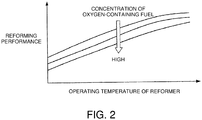
- FIG. 2 is a conceptual view showing a relation between temperature characteristics that show reforming performance of the reformer 24 with respect to temperature, and the concentration of the oxygen-containing fuel in gas flowing into the reformer 24.
- the horizontal axis represents operating temperature of the reformer 24, and the vertical axis represents reforming performance of the reformer 24.
- the reforming performance of the reformer 24 is degraded, the amount of the fuel gas generated in the reformer 24 is reduced, and a supply flow rate of hydrogen gas to the fuel cell stack 10 from the reformer 24 becomes insufficient.
- the controller 50 acquires a concentration parameter in order to specify the concentration of the oxygen-containing fuel in the mixed gas that flows into the reformer 24, and then changes an operating state of the reformer 24 in accordance with the magnitude of the concentration parameter.
- the controller 50 configures a detecting unit that estimates the concentration of the oxygen-containing fuel in the mixed gas that is supplied to the reformer 24.
- the controller 50 acquires a detection value of the fuel concentration sensor 51, detection values of the entry temperature sensor 52 and the exit temperature sensor 53, or a detection value of the FC output sensor 54, as the concentration parameter. Then, the controller 50 changes an operation amount of at least either one of auxiliary machines that are the fuel pump 22 and the discharged gas control valve 42, in accordance with the magnitude of the acquired detection value.
- FIG. 3 is a flowchart showing an example of processing steps regarding an operation control method by which the operating state of the reformer 24 is controlled.
- step S10 the controller 50 is programmed to acquire a temperature difference ⁇ T between an entry to and an exit from the reformer 24.
- the temperature difference ⁇ T is correlated with a concentration of the oxygen-containing fuel contained in the mixed gas that flows into the reformer 24.
- the controller 50 acquires a temperature difference that is obtained by deducting the detection value of the exit temperature sensor 53 from the detection value of the entry temperature sensor 52 as the temperature difference ⁇ T between the entry to and the exit from the reformer 24.
- the relation between the concentration of the oxygen-containing fuel in the mixed gas in the reformer 24, and the temperature difference ⁇ T between the entry to and the exit from the reformer 24 is described later with reference to FIG. 4 .
- step S20 the controller 50 is programmed to determine whether or not the temperature difference ⁇ T between the entry to and the exit from the reformer 24 is equal to or less than an operation change threshold value T1 of the reformer 24.
- the controller 50 determines that the concentration of the oxygen-containing fuel in the mixed gas in the reformer 24 is close to an optimal value, in other words, the concentration of the oxygen-containing fuel is not high. Then, the controller 50 returns to the processing of step S10.
- the foregoing operation change threshold value T1 is a threshold value for changing the operating state of the reformer 24.
- the operation change threshold value T 1 is set to a temperature difference between the entry to and the exit from the reformer 24 such that a supply flow rate of the fuel gas to the fuel cell stack 10 from the reformer 24 does not fall below a lower limit value of a required fuel gas flow rate necessary for power generation in the fuel cell stack 10.
- the operation change threshold value T1 is set so that a ratio of an amount of the fuel gas generated with respect to a supply amount of the mixed gas to the reformer 24 is maintained at a certain value or larger.
- the operation change threshold value T1 is set in advance based on experimental data and simulation results. In this embodiment, the operation change threshold value T1 is set to about 200 °C.
- step S30 when the temperature difference ⁇ T between the entry to and the exit from the reformer 24 is equal to or less than the operation change threshold value T 1, the controller 50 is programmed to determine that the concentration of the oxygen-containing fuel in the mixed gas that flows into the reformer 24 is high, and executes heating control for the reformer 24.
- the controller 50 increases an opening degree of the discharged gas control valve 42 by a predetermined step width so as to increase a discharged gas supply amount to the reformer 24. Accordingly, the discharged gas control valve 42 is opened, and an amount of heat of the discharged gas supplied to the reformer 24 increases, and therefore the operating temperature of the reformer 24 rises.
- step S40 after predetermined time has elapsed, the controller 50 is programmed to newly acquire the temperature difference ⁇ T between the entry to and the exit from the reformer 24, and determines whether or not the temperature difference ⁇ T is equal to or higher than a change cancellation threshold value T2 of the reformer 24.
- the foregoing change cancellation threshold value T2 is a threshold value for returning the operating state of the reformer 24 to the state before the change.
- the change cancellation threshold value T2 is set to a temperature difference between the entry to and the exit from the reformer 24 with which the reforming performance of the reformer 24 is maintained sufficiently.
- the change cancellation threshold value T2 may be the same as or smaller than the operation change threshold value T1.
- the controller 50 When the temperature difference ⁇ T between the entry to and the exit from the reformer 24 is less than the change cancellation threshold value T2, the controller 50 returns to the processing of the step S30, and further increases the opening degree of the discharged gas control valve 42 by the predetermined step width.
- the controller 50 determines that the gas composition in the reformer 24 has improved, stops the heating control for the reformer 24, and ends the series of processing steps related to the operation control method for the reformer 24.
- FIG. 4 is a timing chart showing an example of the heating control by which the opening degree of the discharged gas control valve 42 is controlled and the reformer 24 is heated.
- the broken line represents entry temperature of the reformer 24, and the solid line represents exit temperature of the reformer 24.
- the vertical axis shows operating temperature of the reformer 24, and the horizontal axis shows operating time of the reformer 24.
- the concentration of the oxygen-containing fuel in the mixed gas that flows into the reformer 24 becomes high, and the endothermic reaction in the reformer 24 progresses, and the exit temperature of the reformer 24 decreases.
- the temperature difference ⁇ T between the entry to and the exit from the reformer 24 increases to the operation change threshold value T1.
- T1 the operation change threshold value
- the temperature difference ⁇ T between the entry to and the exit from the reformer 24 becomes small.
- the temperature difference ⁇ T between the entry to and the exit from the reformer 24 is correlated with the ethanol concentration in the mixed gas.
- the controller 50 executes the heating control for the reformer 24 in order to change the operating state of the reformer 24.
- the controller 50 increases the opening degree of the discharged gas control valve 42 to a predetermined value so that a supply amount of the discharged gas to the reformer 24 increases. Because of this, an amount of heat of the discharged gas supplied to the reformer 24 is increased, and the endothermic reaction in the reformer 24 progresses more easily, and the exit temperature of the reformer 24 decreases. Thus, the gas composition in the reformer 24 is improved gradually.
- the controller 50 stops the heating control for the reformer 24 in order to return the operating state of the reformer 24 to the operating state before the change.
- the controller 50 sets the opening degree of the discharged gas control valve 42 to the value before the change or a specific value so that the temperature difference ⁇ T between the entry to and the exit from the reformer 24 is maintained. Because of this, it is possible to restrain a decrease in a generation amount of the fuel gas due to a decrease in the concentration of the oxygen-containing fuel in the mixed gas that flows into the reformer 24.
- FIG. 5 is a view describing another example of the heating control for the reformer 24.
- FIG. 5 shows a relation between operating temperature of the reformer 24 and an optimal temperature difference between the entry to and the exit from the reformer 24 for each concentration of the oxygen-containing fuel in the mixed gas that flows into the reformer 24.
- the optimal temperature difference between the entry to and the exit from the reformer 24 represents an optimal value of the temperature difference between the entry to and the exit from the reformer 24.
- the optimal temperature difference between the entry to and the exit from the reformer 24 at normal operating temperature To1 of the reformer 24 is set as a target temperature difference ⁇ Tt.
- Target operating temperature To2 of the reformer 24 is set so that the optimal temperature difference between the entry to and the exit from the reformer 24 coincides with the target temperature difference ⁇ Tt at the upper limit value of the concentration of the oxygen-containing fuel.
- step S20 shown in FIG. 2 when the temperature difference ⁇ T between the entry to and the exit from the reformer 24 becomes equal to or smaller than the operation change threshold value T1, the controller 50 may increase the operating temperature of the reformer 24 to the target operating temperature To2.
- the entry temperature of the reformer 24, the exit temperature of the reformer 24, or an average value of the entry temperature and the exit temperature of the reformer 24 may be used as the operating temperature of the reformer 24.
- the target operating temperature To2 of the reformer 24 is obtained so that the optimal temperature difference between the entry to and the exit from the reformer 24 at the upper limit value of the concentration of the oxygen-containing fuel of the reformer 24 becomes the target temperature difference ⁇ Tt.
- the target operating temperature of the reformer 24 is obtained for each concentration of the oxygen-containing fuel based on the target temperature difference ⁇ Tt at the normal operating temperature To1 of the reformer 24.
- the controller 50 may change target operating temperature of the reformer 24 so that the temperature difference ⁇ T between the entry to and the exit from the reformer 24 at the normal operating temperature To1 of the reformer 24 becomes the target temperature difference ⁇ Tt. In such a case, the controller 50 reduces the target operating temperature of the reformer 24 as an excessively high concentration of the oxygen-containing fuel in the gas flowing into the reformer 24 is reduced to the optimal value.
- the fuel cell system 100 supplies the fuel gas and the oxidant gas to a fuel cell that configures the fuel cell stack 10 so that the fuel cell stack 10 generates power.
- the fuel cell system 100 includes the fuel tank 21, the reformer 24, and the fuel pump 22.
- the fuel tank 21 stores the aqueous solution containing the oxygen-containing fuel.
- the reformer 24 reforms the mixed gas of steam and the oxygen-contained fuel gas, and generates the fuel gas, the mixed gas being obtained by vaporization of the aqueous solution.
- the fuel pump 22 configures the actuator that supplies the mixed gas to the reformer 24.
- the fuel cell system 100 includes the discharged gas combustor 41 and the discharged gas control valve 42 that configure the heating device that heats the reformer 24, and the detecting unit that estimates or detects a concentration of the oxygen-containing fuel in the mixed gas supplied to the reformer 24.
- This detecting unit includes, for example, at least one of the controller 50, the fuel concentration sensor 51, both of the entry temperature sensor 52 and the exit temperature sensor 53, and the FC output sensor 54.
- the fuel cell system 100 includes the controller 50 that controls operations of the fuel pump 22 and the discharged gas control valve 42 so that the fuel cell stack 10 generates power.
- the controller 50 increase a thermal dose (an amount of heat) to the reformer 24 using the discharged gas control valve 42.
- the controller 50 reduces a supply amount of the mixed gas to the reformer 24 using the fuel pump 22.
- the controller 50 increases the operation amount of the discharged gas control valve 42 that represents the opening degree of the discharged gas control valve 42, or decreases the operation amount of the fuel pump 22 that represents rotation speed of the fuel pump 22.
- the concentration of the oxygen-containing fuel in the aqueous solution stored in the fuel tank 21 is reduced over time due to, for example, a difference in volatility between the oxygen-containing fuel and water. Because the concentration of the oxygen-containing fuel in the mixed gas supplied to the reformer 24 is reduced accordingly, there is a concern that the gas composition in the reformer 24 is deteriorated and a supply amount of the fuel gas to the fuel cell stack 10 becomes insufficient.
- the controller 50 when the concentration of the oxygen-containing fuel in the mixed gas is high, compared to when the concentration is low, the controller 50 reduces the operation amount of the fuel pump 22 or increases the operation amount of the discharged gas control valve 42. Thus, it is possible to restrain deterioration of the gas composition in the reformer 24.
- the controller 50 controls the fuel pump 22 so as to reduce a supply amount of the mixed gas to the reformer 24. This restrains the oxygen-containing fuel from being oversupplied to the reformer 24, and the gas composition in the reformer 24 is thus improved. Thus, it is possible to avoid an insufficient supply of the fuel gas to the fuel cell stack 10.
- the controller 50 controls the fuel pump 22 so as to increase a supply amount of the mixed gas to the reformer 24.
- the controller 50 controls the fuel pump 22 so as to increase a supply amount of the mixed gas to the reformer 24.
- the fuel cell system 100 that is able to store a mixture of the oxygen-containing fuel and water in the single fuel tank 21. This means that it is not necessary to separately provide a water storage tank in which pure water is stored, and a fuel tank in which the oxygen-containing fuel is stored, thus making it possible to have a simple configuration of the fuel cell system 100 that reforms the mixed gas.
- the entry temperature sensor 52 of the reformer 24 detects supply temperature of the mixed gas supplied to the reformer 24, and the exit temperature sensor 53 detects discharge temperature of the fuel gas discharged from the reformer 24 as the concentration parameters correlated with the concentration of the oxygen-containing fuel.
- the controller 50 calculates the temperature difference ⁇ T between the entry temperature of the reformer 24 corresponding to the foregoing supply temperature of the mixed gas, and the exit temperature of the reformer 24 corresponding to the foregoing discharge temperature of the fuel gas.
- the controller 50 reduces the operation amount of the fuel pump 22 or increases the operation amount of the discharged gas control valve 42.
- the concentration of the oxygen-containing fuel in the mixed gas flowing into the reformer 24 is too high, the gas composition in the reformer 24 is deteriorated, and chemical reactions for the endothermic reaction are inhibited.
- the temperature difference ⁇ T between the entry to and the exit from the reformer 24 becomes small.
- the temperature difference ⁇ T between the entry to and the exit from the reformer 24 has a correlation with the concentration of the oxygen-containing fuel in the mixed gas that flows into the reformer 24.
- the controller 50 uses the foregoing correlation so as to restrain degradation of the reforming performance of the reformer 24. Specifically, as described in step S30 in FIG. 3 , the controller 50 increases the opening degree of the discharged gas control valve 42 when the temperature difference ⁇ T between the entry to and the exit from the reformer 24 is equal to or smaller than the operation change threshold value T1.
- the entry temperature sensor 52 and the exit temperature sensor 53 that are already provided in the reformer 24 can be diverted. Then, when the temperature difference ⁇ T between the entry to and the exit from the reformer 24 is equal to or smaller than the operation change threshold value T1, the controller 50 determines that the concentration of the oxygen-containing fuel of the mixed gas is high, and increases operating temperature of the reformer 24. Thus, the reforming performance of the reformer 24 is improved, thereby restraining a reduction of the supply amount of the fuel gas to the fuel cell stack 10.
- the controller 50 estimates whether or not the gas composition in the reformer 24 is deteriorated based on the temperature difference ⁇ T between the entry to and the exit from the reformer 24 without estimating the concentration of the oxygen-containing fuel in the mixed gas that flows into the reformer 24.
- the controller 50 may estimate the concentration of the oxygen-containing fuel in the mixed gas based on the temperature difference ⁇ T between the entry to and the exit from the reformer 24.
- a temperature map showing a relation between the temperature difference between the entry to and the exit from the reformer 24 and the concentration of the oxygen-containing fuel in the mixed gas is stored in the controller 50 in advance, and the controller 50 refers to the temperature map once the controller 50 calculates the temperature difference ⁇ T between the entry to and the exit from the reformer 24. Then, the controller 50 estimates the concentration of the oxygen-containing fuel related to the calculated temperature difference ⁇ T between the entry to and the exit from the reformer 24.
- the controller 50 may prioritize the heating control by which a thermal dose from the discharged gas control valve 42 to the reformer 24 is increased, over the reduction control by which a supply amount of the mixed gas from the fuel pump 22 to the reformer 24 is reduced. For example, when the temperature difference ⁇ T between the entry to and the exit from the reformer 24 is equal to or smaller than the operation change threshold value T1, the controller 50 first controls the discharged gas control valve 42 so as to heat the reformer 24.
- the controller 50 controls the fuel pump 22 and reduces a supply amount of the mixed gas to the reformer 24.
- the reduction control is executed when the reformer 24 is not heated sufficiently due to a response delay of the heating control.
- FIG. 6 is a conceptual view showing a relation between a concentration of oxygen-containing fuel in gas flowing into a reformer 24, and an output of a fuel cell stack 10.
- the output of the fuel cell stack 10 is correlated with the concentration of the oxygen-containing fuel in the reformer 24. Therefore, when a detection value or an estimate value of an output of the fuel cell stack 10 is reduced and falls below a target output of the fuel cell stack 10, it is possible to estimate that the concentration of the oxygen-containing fuel in the mixed gas flowing into the reformer 24 is high.
- FIG. 7 is a flowchart showing an example of processing steps regarding an operation control method for the reformer 24 according to the second embodiment of the invention.
- Step S11 a controller 50 acquires a detection value from an FC output sensor 54.
- the detection value shows output power P of the fuel cell stack 10.
- step S21 the controller 50 determines whether or not the output power P of the fuel cell stack 10 is equal to or smaller than an operation change threshold value P1 of the reformer 24. Then, when the output power P of the fuel cell stack 10 exceeds the operation change threshold value PI, the controller 50 determines that the concentration of the oxygen-containing fuel in the mixed gas flowing into the reformer 24 is not high, and returns to the processing of the step S11.
- the foregoing operation change threshold value P1 is set to output power of the fuel cell stack 10 by which a supply flow rate of the fuel gas from the reformer 24 to the fuel cell stack 10 does not fall below a lower limit value of a required flow rate.
- the operation change threshold value P1 is determined based on a value of output power of the fuel cell stack 10 corresponding to the specific value CO shown in FIG. 6 .
- the operation change threshold value P1 is set to a power value that is 10% of a rated output of the fuel cell stack 10.
- step S31 when the output power P of the fuel cell stack 10 is equal to or smaller than the operation change threshold value PI, the controller 50 determines that a concentration of the oxygen-containing fuel in the mixed gas flowing into the reformer 24 is high. Then, the controller 50 executes heating control for the reformer 24 as described in the step S30 in FIG. 3 .
- step S41 after an elapse of a predetermined period of time, the controller 50 newly obtains the output power P of the fuel cell stack 10, and determines whether or not the output power P is equal to or larger than a change cancellation threshold value P2 of the reformer 24.
- the change cancellation threshold value P2 described above is set to output power of the fuel cell stack 10 by which the reforming performance of the reformer 24 is maintained sufficiently.
- the change cancellation threshold value P2 is set to, for example, a value larger than a value of output power of the fuel cell stack 10 corresponding to the specific value CO shown in FIG. 6 .
- the controller 50 returns to the processing of the step S31 and increases an opening degree of a discharged gas control valve 42 by a predetermined step width.
- the controller 50 determines that the gas composition in the reformer 24 has improved, and ends the series of processing steps related to the operation control method for the reformer 24.
- the processing of the step S40 shown in FIG. 3 may be executed instead of the processing of the step S41.
- the FC output sensor 54 shown in FIG 1 detects the output power P of the fuel cell stack 10 as a concentration parameter that is correlated with a concentration of the oxygen-containing fuel in the mixed gas.
- the concentration of the oxygen-containing fuel in the mixed gas flowing into the reformer 24 becomes high with respect to the specific value C0, the gas composition in the reformer 24 is deteriorated, and output power of the fuel cell stack 10 is thus reduced. This shows that an output of the fuel cell stack 10 is correlated with the concentration of the oxygen-containing fuel.
- the controller 50 increases an operation amount of the discharged gas control valve 42 that represents an opening degree of the discharged gas control valve 42 so that the output power P of the fuel cell stack 10 becomes the change cancellation threshold value P2 that is a predetermined value. This means that the controller 50 changes the operation amount that is the opening degree of the discharged gas control valve 42 from a value at the time of a normal operation in accordance with the output of the fuel cell stack 10.
- the controller 50 changes an operating state of the reformer 24 with use of the output power P of the fuel cell stack 10. As described above, it is possible to change the operating state of the reformer 24 as the FC output sensor 54 that is usually provided in the fuel cell stack 10 is diverted.
- the controller 50 estimates deterioration of the gas composition in the reformer 24 based on the output power P of the fuel cell stack 10 without estimating the concentration of the oxygen-containing fuel in the mixed gas that flows into the reformer 24.
- the controller 50 may estimate the concentration of the oxygen-containing fuel in the mixed gas based on the output power P of the fuel cell stack 10.
- an output map showing a relation between the output power of the fuel cell stack 10 and the concentration of the oxygen-containing fuel in the mixed gas is stored in the controller 50 in advance.
- the output power P of the fuel cell stack 10 is used as the concentration parameter by which the concentration of the oxygen-containing fuel in the mixed gas is specified.
- the detection value of the fuel concentration sensor 51 shown in FIG. 1 may be used.
- FIG. 8 is a flowchart showing an example of processing steps related to an operation control method for a reformer 24 according to a third embodiment of the invention.
- a controller 50 acquires a detection value from a fuel concentration sensor 51.
- the detection value represents a concentration C of oxygen-containing fuel in aqueous solution in a fuel tank 21.
- step S22 the controller 50 determines whether or not the concentration C of the oxygen-containing fuel in the aqueous solution in the fuel tank 21 is equal to or larger than an operation change threshold value C1 of the reformer 24. Then, when the concentration C of the oxygen-containing fuel falls below the operation change threshold value C1, the controller 50 determines that the concentration of the oxygen-containing fuel in the mixed gas flowing into the reformer 24 is not high, and returns to the processing of the step S12.
- the operation change threshold value C1 is set to a concentration of the oxygen-containing fuel in the fuel tank 21 by which a supply flow rate of fuel gas from the reformer 24 to the fuel cell stack 10 does not fall below a lower limit value of a required flow rate.
- the operation change threshold value C1 is set to 50%vol.
- the controller 50 determines that the concentration of the oxygen-containing fuel in the mixed gas flowing into the reformer 24 is high. Then, as described in the step S30 in FIG. 3 , the controller 50 executes heating control for the reformer 24.
- step S42 after an elapse of a predetermined period of time, the controller 50 newly acquires the concentration C of the oxygen-containing fuel, and determines whether or not the concentration C is equal to or less than a change cancellation threshold value C2 of the reformer 24.
- the foregoing change cancellation threshold value C2 is set to a concentration of the oxygen-containing fuel in the fuel tank 21 by which the reforming performance of the reformer 24 is maintained sufficiently.
- the controller 50 returns to the processing of the step S32, and increases an opening degree of a discharged gas control valve 42 by a predetermined step width.
- the controller 50 determines that the gas composition in the reformer 24 is not deteriorated, and ends the series of processing steps related to the operation control method for the reformer 24.
- the processing of the step S40 shown in FIG. 3 or the processing of the step S41 shown in FIG. 7 may be executed instead of the processing of the step S42.
- the fuel concentration sensor 51 is provided in the fuel tank 21, and detects a concentration of the oxygen-containing fuel contained in the aqueous solution as the concentration parameter.
- an error is smaller compared to an estimate value based on the temperature difference ⁇ T between the entry to and the exit from the reformer 24 or an estimate value based on output power P of the fuel cell stack 10.
- the controller 50 is able to heat the reformer 24 or reduce the mixed gas to the reformer 24 precisely. Therefore, it is possible avoid an insufficient supply of the fuel gas to the fuel cell stack 10 more reliably.
- the reformer 24 is heated as the opening degree of the discharged gas control valve 42 is increased so as to increase a discharged gas supply amount to the reformer 24.
- the method for heating the reformer 24 is not limited to this.
- another method for heating the reformer 24 is described with reference to FIG. 9 .
- FIG. 9 is a configuration view showing an example of a configuration of a fuel cell system 101 according the fourth embodiment of the invention.
- the fuel cell system 101 includes a heater 43 instead of the discharged gas control valve 42 of the fuel cell system 100 shown in FIG. 1 .
- the rest of the configuration is the same as that of the fuel cell system 100, and detailed description of the rest of the configuration is omitted.
- the heater 43 configures a heating device that heats a reformer 24.
- the heater 43 is provided around the reformer 24 and supplies heat to the reformer 24.
- a calorific value of the heater 43 is controlled by a controller 50.
- the controller 50 increases a calorific value of the heater 43 when a concentration of oxygen-containing fuel in mixed gas that flows into the reformer 24 is high.
- the controller 50 detects a concentration parameter related to a concentration of the oxygen-containing fuel, and determines whether or not the detected concentration parameter exceeds a given determination threshold value.
- the determination threshold value is a threshold value that is set in order to determine whether or not reforming performance of the reformer 24 is degraded. For example, when the detected concentration parameter exceeds the given determination threshold value, the controller 50 determines that the concentration of the oxygen-containing fuel in the mixed gas is high, and switches an operating state of the heater 43 from a stopped state (OFF) to a heating state (ON).
- FIG. 10 is a flowchart showing an example of processing steps regarding an operation control method for the reformer 24 according to this embodiment.
- the controller 50 executes the processing of the step S33 instead of the processing of the step S30 in the operation control method shown in FIG. 3 . Since the rest of the steps are the same as the steps S10, S20, and S30 shown in FIG. 3 , they are denoted by the same reference numerals, respectively, and the description thereof is omitted.
- step S33 when the temperature difference ⁇ T between the entry to and the exit from the reformer 24 is equal to or less than the foregoing operation change threshold value T1, the controller 50 increases a calorific value of the heater 43. Since the reformer 24 is thus heated, it is possible to increase operating temperature of the reformer 24 so that an endothermic reaction in the reformer 24 is promoted.
- the controller 50 switches the operating state of the heater 43 from OFF to ON.
- the controller 50 may increase a calorific value of the heater 43 to a predetermined value.
- controller 50 proceeds to the processing of step S40, and causes the heater 43 to heat the reformer 24 until the temperature difference ⁇ T between the entry to and the exit from the reformer 24 is equal to or larger than the change cancellation threshold value T2.
- the controller 50 increases the operating temperature of the heater 43. This restrains deterioration of the gas composition in the reformer 24, and it is thus possible to avoid a situation where a supply amount of the fuel gas to the fuel cell stack 10 becomes insufficient.
- the concentration parameter is not limited to this.
- the output power P of the fuel cell stack 10 the concentration C of the oxygen-containing fuel in the fuel tank 21, and so on, which are correlated with the concentration parameter, may be used.
- the discharged gas from the discharged gas combustor 41 is supplied to the reformer 24, and heat generated in the heater 43 is also supplied to the reformer 24, thereby heating the reformer 24.
- the reformer 24 may be heated only by the heater 43.
- the fuel cell system 101 includes the heater 43 as the heating device in addition to a heating structure that supplies the discharged gas from the discharged gas combustor 41 to the reformer 24. Because of this, when the temperature difference ⁇ T between the entry to and the exit from the reformer 24 is equal to or less than the operation change threshold value T1, it is possible to ensure that the reformer 24 is heated regardless of a cumbustion status of the discharged gas combustor 41.
- the heating control for the reformer 24 is carried out so as to restrain deterioration of the gas composition in the reformer 24 due to an excessive concentration of the oxygen-containing fuel.
- a controller 50 according to a fifth embodiment of the invention reduces a supply flow rate of mixed gas that is supplied to a reformer 24 when a concentration parameter related to a concentration of oxygen-containing fuel in the reformer 24 exceeds a given determination threshold value.
- a fuel cell system according to this embodiment has the configuration of the fuel cell system 100 shown in FIG. 1 .
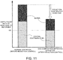
- FIG. 11 describes a control method for controlling the supply flow rate of the mixed gas to the reformer 24 in this embodiment.
- the lower limit value Q0 regarding the supply amount of the oxygen-containing fuel is calculated based on a target power generation amount that is required for power generation by the fuel cell stack 10. For example, the larger the target power generation amount of the fuel cell stack 10 becomes, the larger the lower limit value Q0 becomes.
- the controller 50 changes an operation state of the reformer 24 from a normal operation to a gas composition improving operation in order to restrain deterioration of the gas composition in the reformer 24.
- the controller 50 reduces the supply amount of the mixed gas so that the concentration of the oxygen-containing fuel in the mixed gas that flows into the reformer 24 does not fall below the lower limit value Q0.
- the controller 50 controls rotation speed of a fuel pump 22 shown in FIG. 1 so as to control the supply flow rate of the mixed gas from an evaporator 23 to the reformer 24.
- the controller 50 controls rotation speed of a fuel pump 22 shown in FIG. 1 so as to control the supply flow rate of the mixed gas from an evaporator 23 to the reformer 24.
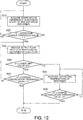
- FIG. 12 is a flowchart showing an example of processing steps regarding an operation control method for the reformer 24 according to this embodiment.
- the controller 50 executes processing of steps S34 to S36, and steps S44 and S45, instead of the processing of the steps S30 and S40 in the operation control method shown in FIG. 3 . Since the rest of the processing is the same as the processing of the steps S10 and S20 shown in FIG. 3 , it is denoted by the same reference numeral and the description thereof is omitted.
- the controller 50 executes a reduction control for the mixed gas with respect to the reformer 24. For example, the controller 50 reduces rotation speed of the fuel pump 22 by a specific step width so that a supply flow rate Q of the mixed gas to the reformer 24 is reduced.
- the supply flow rate of the oxygen-containing fuel to the reformer 24 is reduced and it is thus possible to improve the gas composition in the reformer 24. Accordingly, a chemical reaction for an endothermic reaction that does not contribute to generation of the fuel gas in the reformer 24 is restrained, and the temperature difference ⁇ T between the entry to and the exit from the reformer 24 becomes small.
- the controller 50 determines whether or not the supply flow rate Q of the mixed gas to the reformer 24 is equal to or larger than a lower limit value Q1.
- the lower limit value Q1 is set based on experimental data, simulation results, or the like, and is set in advance in consideration of the lower limit value Q0 of the supply flow rate of the oxygen-containing fuel shown in FIG. 11 , for example.
- the controller 50 After an elapse of a predetermined period of time, the controller 50 newly acquires the temperature difference ⁇ T between the entry to and the exit from the reformer 24, and determines whether or not the temperature difference ⁇ T between the entry to and the exit from the reformer 24 is equal to or larger than a change cancellation threshold value T3.
- the change cancellation threshold value T3 is set based on experimental data, simulation results, or the like, similarly to the change cancellation threshold value T2 described for the step S40 in FIG. 3 .
- the controller 50 stops the reduction control for the mixed gas with respect to the reformer 24, and ends the operation control method for the reformer 24.
- the controller 50 returns to the processing of the step S34, and further reduces the rotation speed of the fuel pump 22 by a specific step width so that the supply flow rate Q of the mixed gas is reduced further.
- step S35 When the supply flow rate Q of the mixed gas to the reformer 24 falls below the lower limit value Q1 in the step S35, the controller 50 increases the rotation speed of the fuel pump 22 so that the supply flow rate Q of the mixed gas increases to the lower limit value Q1, and proceeds to the processing of step S36.
- step S36 when the supply flow rate Q of the mixed gas reaches the lower limit value Q1, the controller 50 increases operating temperature of the reformer 24 by a predetermined step width.
- the controller 50 executes the processing of the step S30 shown in FIG. 3 .
- the heater 43 may be provided around the reformer 24, and then the processing of the step S33 shown in FIG. 10 may be executed.
- the operating temperature of the reformer 24 increases, and the gas composition in the reformer 24 is improved.
- the controller 50 After an elapse of a predetermined period of time, the controller 50 newly acquires the temperature difference ⁇ T between the entry to and the exit from the reformer 24, and determines whether or not the temperature difference ⁇ T between the entry to and the exit from the reformer 24 is equal to or larger than the change cancellation threshold value T3.
- the controller 50 returns to the processing of the step S36, and increases the operating temperature of the reformer 24 by a predetermined step width.
- the controller 50 determines that the gas composition of the reformer 24 has improved, stops the heating control for the reformer 24, and ends the series of the processing steps related to the operation control method for the reformer 24.
- the controller 50 reduces the rotation speed of the fuel pump 22 when the temperature difference ⁇ T between the entry to and the exit from the reformer 24, which is one of the concentration parameters, is equal to or less than the operation change threshold value T1. This means that, as shown in FIG. 11 , the controller 50 reduces an operation amount of the fuel pump 22 so that a supply amount of the mixed gas to the reformer 24 is reduced in accordance with the concentration parameter.
- a sensor that is able to detect a concentration of the oxygen-containing fuel in the mixed gas flowing into the reformer 24 may be provided in the reformer 24, and a detection value of the sensor may be used as the concentration parameter.
- the controller 50 may be provided with a map, and a counter that measures time. The map shows a relation between time elapsed after a supply of aqueous solution to the fuel tank 21 and a concentration of the oxygen-containing fuel in the aqueous solution. Then, after the aqueous solution is supplied to the fuel tank 21, the controller 50 may acquire a value of the counter as the concentration parameter. Thereafter, the controller 50 estimates a concentration of the oxygen-containing fuel associated with the value of the counter.
- degradation of the reforming performance of the reformer 24 is determined with use of one of the concentration parameters, that are the temperature difference ⁇ T between the entry to and the exit from the reformer 24, the output power P of the fuel cell stack 10, and the concentration C of the oxygen-containing fuel in the fuel tank 21.
- concentration parameters that are the temperature difference ⁇ T between the entry to and the exit from the reformer 24, the output power P of the fuel cell stack 10, and the concentration C of the oxygen-containing fuel in the fuel tank 21.
- an operating state of the reformer 24 may be changed when more than one concentration parameters exceed given determination threshold values, respectively.
- the evaporator 23 and the reformer 24 are provided separately from each other.
- the evaporator 23 and the reformer 24 may be configured integrally. In this case, it is also possible to obtain the effects of this embodiment.
Landscapes
- Engineering & Computer Science (AREA)
- Chemical & Material Sciences (AREA)
- Life Sciences & Earth Sciences (AREA)
- Manufacturing & Machinery (AREA)
- Sustainable Development (AREA)
- Sustainable Energy (AREA)
- Chemical Kinetics & Catalysis (AREA)
- Electrochemistry (AREA)
- General Chemical & Material Sciences (AREA)
- Combustion & Propulsion (AREA)
- Fuel Cell (AREA)
Claims (8)
- Brennstoffzellen-System, in dem Brennstoff-Gas und Oxidant-Gas einer Brennstoffzelle (10) zugeführt werden, so dass die Brennstoffzelle (10) Strom erzeugt, wobei das Brennstoffzellen-System umfasst:einen Tank (21), der zum Speichern von wässriger Lösung eingerichtet ist, die sauerstoffhaltigen Brennstoff enthält;einen Reformer (24), der zum Reformieren von Mischgas eingerichtet ist, das gewonnen wird, wenn die wässrige Lösung verdampft wird, wobei der Reformer (24) so das Brennstoff-Gas erzeugt;ein Stellglied (22), das zum Zuführen des Mischgases zu dem Reformer (24) eingerichtet ist;eine Heizvorrichtung (41, 42), die zum Erhitzen des Reformers (24) eingerichtet ist; sowieeine Steuerungseinrichtung (50), die so programmiert ist, dass sie Funktionen des Stellgliedes (22) und der Heizvorrichtung (41, 42) so steuert, dass die Brennstoffzelle (10) Strom erzeugt;dadurch gekennzeichnet, dass das System des Weiteren umfasst:eine Erfassungs-Einheit (51, 52, 53, 54), die so eingerichtet ist, dass sie eine Konzentration des sauerstoffhaltigen Brennstoffs in dem Mischgas schätzt oder erfasst, dass dem Reformer (24) zugeführt wird; wobeidie Steuerungseinrichtung so programmiert ist, dass sie, wenn die Konzentration des sauerstoffhaltigen Brennstoffs hoch ist, im Unterschied zu dem Fall, in dem die Konzentration niedrig ist, eine Wärmemenge für den Reformer von der Heizvorrichtung (41, 42) vergrößert oder eine Zuführmenge des Mischgases zu dem Reformer (24) durch das Stellglied (22) reduziert.
- Brennstoffzellen-System nach Anspruch 1, wobei die Steuerungseinrichtung (50) so eingerichtet ist, dass sie Steuerung zur Erhitzung gegenüber Steuerung zur Reduzierung priorisiert, wobei die Steuerung zur Erhitzung ausgeführt wird, um die Wärmemenge von der Heizvorrichtung (41, 42) zu vergrößern und die Steuerung zur Reduzierung ausgeführt wird, um die Zuführmenge des Mischgases durch das Stellglied (22) zu reduzieren.
- Brennstoffzellen-System nach Anspruch 1 oder 2, wobeidie Erfassungs-Einheit (52, 53) so eingerichtet ist, dass sie als die Konzentration des sauerstoffhaltigen Brennstoffs Temperatur des dem Reformer (24) zugeführten Mischgases und Temperatur des aus dem Reformer (24) abgeleiteten Brennstoff-Gases erfasst; unddie Steuerungseinrichtung (50), im Unterschied zu dem Fall, in dem eine Temperaturdifferenz zwischen Temperatur des gemischten Gases und Temperatur des Brennstoff-Gases groß ist, wenn die Temperaturdifferenz gering ist, die Wärmemenge für den Reformer (24) vergrößert oder die Zuführmenge des Mischgases zu dem Reformer (24) reduziert.
- Brennstoffzellen-System nach Anspruch 1 oder 2, wobeidie Erfassungs-Einheit (54) so eingerichtet ist, dass sie einen Ausstoß der Brennstoffzelle (10) als die Konzentration des sauerstoffhaltigen Brennstoffs erfasst; unddie Steuerungseinrichtung (50) so eingerichtet ist, dass sie die Wärmemenge für den Reformer (24) vergrößert oder die Zuführmenge des Mischgases für den Reformer (24) reduziert, so dass der Ausstoß der Brennstoffzelle (10) einen vorgegebenen Wert erreicht.
- Brennstoffzellen-System nach Anspruch 1 oder 2, wobei die Erfassungs-Einheit (51) in dem Tank vorhanden ist und eine Konzentration des sauerstoffhaltigen Brennstoffs in der wässrigen Lösung erfasst.
- Brennstoffzellen-System nach Anspruch 1 oder 2, wobei die Erfassungs-Einheit (52, 53) so eingerichtet ist, dass sie die Konzentration des sauerstoffhaltigen Brennstoffs auf Basis einer Temperaturdifferenz zwischen Temperatur des Mischgases und Temperatur des Brennstoff-Gases schätzt.
- Brennstoffzellen-System nach Anspruch 1 oder 2, wobei die Erfassungs-Einheit (54) so eingerichtet ist, dass sie die Konzentration des sauerstoffhaltigen Brennstoffs auf Basis eines Ausstoßes der Brennstoffzelle (10) schätzt.
- Steuerungsverfahren für ein Brennstoffzellen-System, das einen Reformer (24), der Mischgas aus sauerstoffhaltigem Brennstoff-Gas und Dampf reformiert, ein Stellglied (22), das das Mischgas dem Reformer (24) zuführt, sowie eine Heizvorrichtung (41, 42) enthält, die den Reformer erhitzt, wobei das Steuerungsverfahren umfasst:einen Schritt für Steuerung von Stromerzeugung, in dem Stromerzeugung einer Brennstoffzelle (10) durch Zuführen von Brennstoff-Gas zu der Brennstoffzelle (10) gesteuert wird, wobei das Brennstoff-Gas durch den Reformer (24) reformiert wird;dadurch gekennzeichnet, dass das Verfahren des Weiteren umfasst:
einen Schritt zum Steuern von Reformieren, in dem im Unterschied zu dem Fall, in dem eine Konzentration von sauerstoffhaltigem Brennstoff in dem dem Reformer (24) zugeführten Mischgas niedrig ist, ein Maß des Betriebes der Heizvorrichtung (41, 42) vergrößert wird oder ein Maß des Betriebes des Stellgliedes (22) reduziert wird, wenn die Konzentration hoch ist.
Applications Claiming Priority (1)
| Application Number | Priority Date | Filing Date | Title |
|---|---|---|---|
| PCT/JP2017/027549 WO2019021482A1 (ja) | 2017-07-28 | 2017-07-28 | 燃料電池システム及びその制御方法 |
Publications (3)
| Publication Number | Publication Date |
|---|---|
| EP3660968A1 EP3660968A1 (de) | 2020-06-03 |
| EP3660968A4 EP3660968A4 (de) | 2020-07-22 |
| EP3660968B1 true EP3660968B1 (de) | 2021-12-22 |
Family
ID=65039500
Family Applications (1)
| Application Number | Title | Priority Date | Filing Date |
|---|---|---|---|
| EP17918834.7A Active EP3660968B1 (de) | 2017-07-28 | 2017-07-28 | Brennstoffzellensystem und verfahren zur steuerung davon |
Country Status (5)
| Country | Link |
|---|---|
| US (1) | US11108067B2 (de) |
| EP (1) | EP3660968B1 (de) |
| JP (1) | JP6801790B2 (de) |
| CN (1) | CN110959214B (de) |
| WO (1) | WO2019021482A1 (de) |
Families Citing this family (3)
| Publication number | Priority date | Publication date | Assignee | Title |
|---|---|---|---|---|
| JP7087640B2 (ja) | 2018-05-02 | 2022-06-21 | 日産自動車株式会社 | 混合燃料供給装置 |
| CN112310450B (zh) * | 2020-10-30 | 2022-02-18 | 摩氢科技有限公司 | 一种甲醇水燃料重整制氢系统及其控制方法 |
| CN116730253A (zh) * | 2023-05-19 | 2023-09-12 | 武汉雄韬氢雄燃料电池科技有限公司 | 一种适用于叉车的新型大功率高集成度氢电系统 |
Citations (2)
| Publication number | Priority date | Publication date | Assignee | Title |
|---|---|---|---|---|
| US20130130138A1 (en) * | 2011-04-26 | 2013-05-23 | Panasonic Corporation | Hydrogen generation apparatus, fuel cell system, and method of operating the same |
| US20150333347A1 (en) * | 2012-03-19 | 2015-11-19 | Zodiac Aerotechinics | Fuel cell devices for fire and/or explosion prevention |
Family Cites Families (8)
| Publication number | Priority date | Publication date | Assignee | Title |
|---|---|---|---|---|
| JP3879366B2 (ja) | 2000-05-23 | 2007-02-14 | 日産自動車株式会社 | 燃料電池用改質システム |
| JP4610097B2 (ja) * | 2001-02-08 | 2011-01-12 | 日産自動車株式会社 | 燃料改質システム |
| JP3692962B2 (ja) * | 2001-04-16 | 2005-09-07 | 日産自動車株式会社 | 燃料電池システムの制御装置 |
| JP2003178783A (ja) * | 2001-10-02 | 2003-06-27 | Ngk Insulators Ltd | 燃料電池発電装置 |
| KR100718116B1 (ko) * | 2006-05-15 | 2007-05-15 | 삼성에스디아이 주식회사 | 고온용 pem 연료전지 시스템 |
| JP5763405B2 (ja) | 2011-04-28 | 2015-08-12 | 本田技研工業株式会社 | 燃料電池システム |
| CN105152133B (zh) * | 2015-09-06 | 2017-10-31 | 中国船舶重工集团公司第七一二研究所 | 一种用于燃料电池的在线高纯氢气制备系统及其控制方法 |
| CN108370049B (zh) | 2015-12-15 | 2019-10-25 | 日产自动车株式会社 | 燃料电池系统及其控制方法 |
-
2017
- 2017-07-28 US US16/629,649 patent/US11108067B2/en active Active
- 2017-07-28 CN CN201780093470.9A patent/CN110959214B/zh active Active
- 2017-07-28 EP EP17918834.7A patent/EP3660968B1/de active Active
- 2017-07-28 JP JP2019532343A patent/JP6801790B2/ja active Active
- 2017-07-28 WO PCT/JP2017/027549 patent/WO2019021482A1/ja not_active Ceased
Patent Citations (2)
| Publication number | Priority date | Publication date | Assignee | Title |
|---|---|---|---|---|
| US20130130138A1 (en) * | 2011-04-26 | 2013-05-23 | Panasonic Corporation | Hydrogen generation apparatus, fuel cell system, and method of operating the same |
| US20150333347A1 (en) * | 2012-03-19 | 2015-11-19 | Zodiac Aerotechinics | Fuel cell devices for fire and/or explosion prevention |
Also Published As
| Publication number | Publication date |
|---|---|
| JPWO2019021482A1 (ja) | 2020-06-18 |
| WO2019021482A1 (ja) | 2019-01-31 |
| CN110959214B (zh) | 2020-11-13 |
| US11108067B2 (en) | 2021-08-31 |
| EP3660968A4 (de) | 2020-07-22 |
| EP3660968A1 (de) | 2020-06-03 |
| US20200381754A1 (en) | 2020-12-03 |
| CN110959214A (zh) | 2020-04-03 |
| JP6801790B2 (ja) | 2020-12-16 |
Similar Documents
| Publication | Publication Date | Title |
|---|---|---|
| EP3396763B1 (de) | Festoxid-brennstoffzellensystem und verfahren zur steuerung eines festoxid-brennstoffzellensystems | |
| JP5576902B2 (ja) | 燃料電池システム及びその運転方法 | |
| EP3396762B1 (de) | Brennstoffzellensystem und verfahren zur steuerung dieses systems | |
| JP6627887B2 (ja) | 燃料電池システム、及び燃料電池システムの制御方法 | |
| EP3660968B1 (de) | Brennstoffzellensystem und verfahren zur steuerung davon | |
| EP2703341B1 (de) | Betriebsverfahren für einen wasserstoffgenerator | |
| EP3951966B1 (de) | Brennstoffzellensystem und verfahren zur steuerung des brennstoffzellensystems | |
| EP3026748B1 (de) | Brennstoffzellensystem | |
| JP3698101B2 (ja) | 燃料改質型燃料電池システムの制御装置 | |
| US20020160243A1 (en) | Control system for fuel cell | |
| US20090280361A1 (en) | Power supply system and method of controlling the same | |
| JP4611248B2 (ja) | 燃料電池システム | |
| EP4156350B1 (de) | Brennstoffzellensystem und verfahren zur steuerung des brennstoffzellensystems | |
| JP2008300218A (ja) | 燃料電池システム | |
| US20200381755A1 (en) | Fuel cell system and control method for same | |
| JP3879366B2 (ja) | 燃料電池用改質システム | |
| JP5606721B2 (ja) | 触媒反応容器のヒータ制御装置、触媒反応容器のヒータ制御方法及び燃料電池システム | |
| JP2008059877A (ja) | 燃料電池システム | |
| JP7102960B2 (ja) | 燃料電池システムの制御方法及び燃料電池システム | |
| JP2009181793A (ja) | 燃料電池システム | |
| JP7545884B2 (ja) | 燃料電池車両の制御方法、及び、燃料電池車両 | |
| JP2018092920A (ja) | 燃料電池システムおよびその運転方法 | |
| JP4956489B2 (ja) | 燃料電池システム及びその運転方法 | |
| WO2020054048A1 (ja) | 燃料電池システムの制御方法、及び、燃料電池システム |
Legal Events
| Date | Code | Title | Description |
|---|---|---|---|
| STAA | Information on the status of an ep patent application or granted ep patent |
Free format text: STATUS: THE INTERNATIONAL PUBLICATION HAS BEEN MADE |
|
| PUAI | Public reference made under article 153(3) epc to a published international application that has entered the european phase |
Free format text: ORIGINAL CODE: 0009012 |
|
| STAA | Information on the status of an ep patent application or granted ep patent |
Free format text: STATUS: REQUEST FOR EXAMINATION WAS MADE |
|
| 17P | Request for examination filed |
Effective date: 20200226 |
|
| AK | Designated contracting states |
Kind code of ref document: A1 Designated state(s): AL AT BE BG CH CY CZ DE DK EE ES FI FR GB GR HR HU IE IS IT LI LT LU LV MC MK MT NL NO PL PT RO RS SE SI SK SM TR |
|
| AX | Request for extension of the european patent |
Extension state: BA ME |
|
| A4 | Supplementary search report drawn up and despatched |
Effective date: 20200619 |
|
| RIC1 | Information provided on ipc code assigned before grant |
Ipc: H01M 8/04537 20160101ALI20200615BHEP Ipc: H01M 8/04701 20160101ALI20200615BHEP Ipc: H01M 8/04082 20160101ALI20200615BHEP Ipc: H01M 8/04746 20160101ALI20200615BHEP Ipc: H01M 8/0444 20160101ALI20200615BHEP Ipc: H01M 8/0612 20160101AFI20200615BHEP Ipc: H01M 8/04 20160101ALI20200615BHEP Ipc: H01M 8/0432 20160101ALI20200615BHEP Ipc: H01M 8/04014 20160101ALI20200615BHEP Ipc: H01M 8/04007 20160101ALI20200615BHEP |
|
| DAV | Request for validation of the european patent (deleted) | ||
| DAX | Request for extension of the european patent (deleted) | ||
| STAA | Information on the status of an ep patent application or granted ep patent |
Free format text: STATUS: EXAMINATION IS IN PROGRESS |
|
| 17Q | First examination report despatched |
Effective date: 20210302 |
|
| GRAP | Despatch of communication of intention to grant a patent |
Free format text: ORIGINAL CODE: EPIDOSNIGR1 |
|
| GRAJ | Information related to disapproval of communication of intention to grant by the applicant or resumption of examination proceedings by the epo deleted |
Free format text: ORIGINAL CODE: EPIDOSDIGR1 |
|
| GRAP | Despatch of communication of intention to grant a patent |
Free format text: ORIGINAL CODE: EPIDOSNIGR1 |
|
| STAA | Information on the status of an ep patent application or granted ep patent |
Free format text: STATUS: GRANT OF PATENT IS INTENDED |
|
| INTG | Intention to grant announced |
Effective date: 20210910 |
|
| GRAS | Grant fee paid |
Free format text: ORIGINAL CODE: EPIDOSNIGR3 |
|
| GRAA | (expected) grant |
Free format text: ORIGINAL CODE: 0009210 |
|
| STAA | Information on the status of an ep patent application or granted ep patent |
Free format text: STATUS: THE PATENT HAS BEEN GRANTED |
|
| AK | Designated contracting states |
Kind code of ref document: B1 Designated state(s): AL AT BE BG CH CY CZ DE DK EE ES FI FR GB GR HR HU IE IS IT LI LT LU LV MC MK MT NL NO PL PT RO RS SE SI SK SM TR |
|
| REG | Reference to a national code |
Ref country code: GB Ref legal event code: FG4D |
|
| REG | Reference to a national code |
Ref country code: CH Ref legal event code: EP |
|
| REG | Reference to a national code |
Ref country code: DE Ref legal event code: R096 Ref document number: 602017051422 Country of ref document: DE |
|
| REG | Reference to a national code |
Ref country code: AT Ref legal event code: REF Ref document number: 1457657 Country of ref document: AT Kind code of ref document: T Effective date: 20220115 |
|
| REG | Reference to a national code |
Ref country code: IE Ref legal event code: FG4D |
|
| REG | Reference to a national code |
Ref country code: LT Ref legal event code: MG9D |
|
| PG25 | Lapsed in a contracting state [announced via postgrant information from national office to epo] |
Ref country code: RS Free format text: LAPSE BECAUSE OF FAILURE TO SUBMIT A TRANSLATION OF THE DESCRIPTION OR TO PAY THE FEE WITHIN THE PRESCRIBED TIME-LIMIT Effective date: 20211222 Ref country code: LT Free format text: LAPSE BECAUSE OF FAILURE TO SUBMIT A TRANSLATION OF THE DESCRIPTION OR TO PAY THE FEE WITHIN THE PRESCRIBED TIME-LIMIT Effective date: 20211222 Ref country code: FI Free format text: LAPSE BECAUSE OF FAILURE TO SUBMIT A TRANSLATION OF THE DESCRIPTION OR TO PAY THE FEE WITHIN THE PRESCRIBED TIME-LIMIT Effective date: 20211222 Ref country code: BG Free format text: LAPSE BECAUSE OF FAILURE TO SUBMIT A TRANSLATION OF THE DESCRIPTION OR TO PAY THE FEE WITHIN THE PRESCRIBED TIME-LIMIT Effective date: 20220322 |
|
| REG | Reference to a national code |
Ref country code: NL Ref legal event code: MP Effective date: 20211222 |
|
| REG | Reference to a national code |
Ref country code: AT Ref legal event code: MK05 Ref document number: 1457657 Country of ref document: AT Kind code of ref document: T Effective date: 20211222 |
|
| PG25 | Lapsed in a contracting state [announced via postgrant information from national office to epo] |
Ref country code: SE Free format text: LAPSE BECAUSE OF FAILURE TO SUBMIT A TRANSLATION OF THE DESCRIPTION OR TO PAY THE FEE WITHIN THE PRESCRIBED TIME-LIMIT Effective date: 20211222 Ref country code: NO Free format text: LAPSE BECAUSE OF FAILURE TO SUBMIT A TRANSLATION OF THE DESCRIPTION OR TO PAY THE FEE WITHIN THE PRESCRIBED TIME-LIMIT Effective date: 20220322 Ref country code: LV Free format text: LAPSE BECAUSE OF FAILURE TO SUBMIT A TRANSLATION OF THE DESCRIPTION OR TO PAY THE FEE WITHIN THE PRESCRIBED TIME-LIMIT Effective date: 20211222 Ref country code: HR Free format text: LAPSE BECAUSE OF FAILURE TO SUBMIT A TRANSLATION OF THE DESCRIPTION OR TO PAY THE FEE WITHIN THE PRESCRIBED TIME-LIMIT Effective date: 20211222 Ref country code: GR Free format text: LAPSE BECAUSE OF FAILURE TO SUBMIT A TRANSLATION OF THE DESCRIPTION OR TO PAY THE FEE WITHIN THE PRESCRIBED TIME-LIMIT Effective date: 20220323 |
|
| PG25 | Lapsed in a contracting state [announced via postgrant information from national office to epo] |
Ref country code: NL Free format text: LAPSE BECAUSE OF FAILURE TO SUBMIT A TRANSLATION OF THE DESCRIPTION OR TO PAY THE FEE WITHIN THE PRESCRIBED TIME-LIMIT Effective date: 20211222 |
|
| PG25 | Lapsed in a contracting state [announced via postgrant information from national office to epo] |
Ref country code: SM Free format text: LAPSE BECAUSE OF FAILURE TO SUBMIT A TRANSLATION OF THE DESCRIPTION OR TO PAY THE FEE WITHIN THE PRESCRIBED TIME-LIMIT Effective date: 20211222 Ref country code: SK Free format text: LAPSE BECAUSE OF FAILURE TO SUBMIT A TRANSLATION OF THE DESCRIPTION OR TO PAY THE FEE WITHIN THE PRESCRIBED TIME-LIMIT Effective date: 20211222 Ref country code: RO Free format text: LAPSE BECAUSE OF FAILURE TO SUBMIT A TRANSLATION OF THE DESCRIPTION OR TO PAY THE FEE WITHIN THE PRESCRIBED TIME-LIMIT Effective date: 20211222 Ref country code: PT Free format text: LAPSE BECAUSE OF FAILURE TO SUBMIT A TRANSLATION OF THE DESCRIPTION OR TO PAY THE FEE WITHIN THE PRESCRIBED TIME-LIMIT Effective date: 20220422 Ref country code: ES Free format text: LAPSE BECAUSE OF FAILURE TO SUBMIT A TRANSLATION OF THE DESCRIPTION OR TO PAY THE FEE WITHIN THE PRESCRIBED TIME-LIMIT Effective date: 20211222 Ref country code: EE Free format text: LAPSE BECAUSE OF FAILURE TO SUBMIT A TRANSLATION OF THE DESCRIPTION OR TO PAY THE FEE WITHIN THE PRESCRIBED TIME-LIMIT Effective date: 20211222 Ref country code: CZ Free format text: LAPSE BECAUSE OF FAILURE TO SUBMIT A TRANSLATION OF THE DESCRIPTION OR TO PAY THE FEE WITHIN THE PRESCRIBED TIME-LIMIT Effective date: 20211222 |
|
| PG25 | Lapsed in a contracting state [announced via postgrant information from national office to epo] |
Ref country code: PL Free format text: LAPSE BECAUSE OF FAILURE TO SUBMIT A TRANSLATION OF THE DESCRIPTION OR TO PAY THE FEE WITHIN THE PRESCRIBED TIME-LIMIT Effective date: 20211222 Ref country code: AT Free format text: LAPSE BECAUSE OF FAILURE TO SUBMIT A TRANSLATION OF THE DESCRIPTION OR TO PAY THE FEE WITHIN THE PRESCRIBED TIME-LIMIT Effective date: 20211222 |
|
| REG | Reference to a national code |
Ref country code: DE Ref legal event code: R097 Ref document number: 602017051422 Country of ref document: DE |
|
| PG25 | Lapsed in a contracting state [announced via postgrant information from national office to epo] |
Ref country code: IS Free format text: LAPSE BECAUSE OF FAILURE TO SUBMIT A TRANSLATION OF THE DESCRIPTION OR TO PAY THE FEE WITHIN THE PRESCRIBED TIME-LIMIT Effective date: 20220422 |
|
| PLBE | No opposition filed within time limit |
Free format text: ORIGINAL CODE: 0009261 |
|
| STAA | Information on the status of an ep patent application or granted ep patent |
Free format text: STATUS: NO OPPOSITION FILED WITHIN TIME LIMIT |
|
| PG25 | Lapsed in a contracting state [announced via postgrant information from national office to epo] |
Ref country code: DK Free format text: LAPSE BECAUSE OF FAILURE TO SUBMIT A TRANSLATION OF THE DESCRIPTION OR TO PAY THE FEE WITHIN THE PRESCRIBED TIME-LIMIT Effective date: 20211222 Ref country code: AL Free format text: LAPSE BECAUSE OF FAILURE TO SUBMIT A TRANSLATION OF THE DESCRIPTION OR TO PAY THE FEE WITHIN THE PRESCRIBED TIME-LIMIT Effective date: 20211222 |
|
| 26N | No opposition filed |
Effective date: 20220923 |
|
| PG25 | Lapsed in a contracting state [announced via postgrant information from national office to epo] |
Ref country code: SI Free format text: LAPSE BECAUSE OF FAILURE TO SUBMIT A TRANSLATION OF THE DESCRIPTION OR TO PAY THE FEE WITHIN THE PRESCRIBED TIME-LIMIT Effective date: 20211222 Ref country code: MC Free format text: LAPSE BECAUSE OF FAILURE TO SUBMIT A TRANSLATION OF THE DESCRIPTION OR TO PAY THE FEE WITHIN THE PRESCRIBED TIME-LIMIT Effective date: 20211222 |
|
| REG | Reference to a national code |
Ref country code: CH Ref legal event code: PL |
|
| REG | Reference to a national code |
Ref country code: BE Ref legal event code: MM Effective date: 20220731 |
|
| PG25 | Lapsed in a contracting state [announced via postgrant information from national office to epo] |
Ref country code: LU Free format text: LAPSE BECAUSE OF NON-PAYMENT OF DUE FEES Effective date: 20220728 Ref country code: LI Free format text: LAPSE BECAUSE OF NON-PAYMENT OF DUE FEES Effective date: 20220731 Ref country code: CH Free format text: LAPSE BECAUSE OF NON-PAYMENT OF DUE FEES Effective date: 20220731 |
|
| PG25 | Lapsed in a contracting state [announced via postgrant information from national office to epo] |
Ref country code: IT Free format text: LAPSE BECAUSE OF FAILURE TO SUBMIT A TRANSLATION OF THE DESCRIPTION OR TO PAY THE FEE WITHIN THE PRESCRIBED TIME-LIMIT Effective date: 20211222 Ref country code: BE Free format text: LAPSE BECAUSE OF NON-PAYMENT OF DUE FEES Effective date: 20220731 |
|
| PG25 | Lapsed in a contracting state [announced via postgrant information from national office to epo] |
Ref country code: IE Free format text: LAPSE BECAUSE OF NON-PAYMENT OF DUE FEES Effective date: 20220728 |
|
| REG | Reference to a national code |
Ref country code: DE Ref legal event code: R084 Ref document number: 602017051422 Country of ref document: DE |
|
| REG | Reference to a national code |
Ref country code: GB Ref legal event code: 746 Effective date: 20230926 |
|
| PG25 | Lapsed in a contracting state [announced via postgrant information from national office to epo] |
Ref country code: MK Free format text: LAPSE BECAUSE OF FAILURE TO SUBMIT A TRANSLATION OF THE DESCRIPTION OR TO PAY THE FEE WITHIN THE PRESCRIBED TIME-LIMIT Effective date: 20211222 Ref country code: CY Free format text: LAPSE BECAUSE OF FAILURE TO SUBMIT A TRANSLATION OF THE DESCRIPTION OR TO PAY THE FEE WITHIN THE PRESCRIBED TIME-LIMIT Effective date: 20211222 |
|
| PG25 | Lapsed in a contracting state [announced via postgrant information from national office to epo] |
Ref country code: HU Free format text: LAPSE BECAUSE OF FAILURE TO SUBMIT A TRANSLATION OF THE DESCRIPTION OR TO PAY THE FEE WITHIN THE PRESCRIBED TIME-LIMIT; INVALID AB INITIO Effective date: 20170728 |
|
| PG25 | Lapsed in a contracting state [announced via postgrant information from national office to epo] |
Ref country code: MT Free format text: LAPSE BECAUSE OF FAILURE TO SUBMIT A TRANSLATION OF THE DESCRIPTION OR TO PAY THE FEE WITHIN THE PRESCRIBED TIME-LIMIT Effective date: 20211222 |
|
| PGFP | Annual fee paid to national office [announced via postgrant information from national office to epo] |
Ref country code: GB Payment date: 20250619 Year of fee payment: 9 |
|
| PGFP | Annual fee paid to national office [announced via postgrant information from national office to epo] |
Ref country code: FR Payment date: 20250620 Year of fee payment: 9 |
|
| PGFP | Annual fee paid to national office [announced via postgrant information from national office to epo] |
Ref country code: DE Payment date: 20250620 Year of fee payment: 9 |
|
| PG25 | Lapsed in a contracting state [announced via postgrant information from national office to epo] |
Ref country code: TR Free format text: LAPSE BECAUSE OF FAILURE TO SUBMIT A TRANSLATION OF THE DESCRIPTION OR TO PAY THE FEE WITHIN THE PRESCRIBED TIME-LIMIT Effective date: 20211222 |