EP3661008A1 - Fliegende batterie mit wechselstromschalter-pfc-frontend für usv - Google Patents
Fliegende batterie mit wechselstromschalter-pfc-frontend für usv Download PDFInfo
- Publication number
- EP3661008A1 EP3661008A1 EP19209278.1A EP19209278A EP3661008A1 EP 3661008 A1 EP3661008 A1 EP 3661008A1 EP 19209278 A EP19209278 A EP 19209278A EP 3661008 A1 EP3661008 A1 EP 3661008A1
- Authority
- EP
- European Patent Office
- Prior art keywords
- power
- switch
- positive
- bus
- negative
- Prior art date
- Legal status (The legal status is an assumption and is not a legal conclusion. Google has not performed a legal analysis and makes no representation as to the accuracy of the status listed.)
- Pending
Links
Images



Classifications
-
- H—ELECTRICITY
- H02—GENERATION; CONVERSION OR DISTRIBUTION OF ELECTRIC POWER
- H02J—ELECTRIC POWER NETWORKS; CIRCUIT ARRANGEMENTS OR SYSTEMS FOR SUPPLYING OR DISTRIBUTING ELECTRIC POWER; SYSTEMS FOR STORING ELECTRIC ENERGY
- H02J9/00—Circuit arrangements for emergency or stand-by power supply, e.g. for emergency lighting
- H02J9/04—Circuit arrangements for emergency or stand-by power supply, e.g. for emergency lighting in which the distribution system is disconnected from the normal source and connected to a standby source
- H02J9/06—Circuit arrangements for emergency or stand-by power supply, e.g. for emergency lighting in which the distribution system is disconnected from the normal source and connected to a standby source with automatic change-over, e.g. UPS systems
- H02J9/061—Circuit arrangements for emergency or stand-by power supply, e.g. for emergency lighting in which the distribution system is disconnected from the normal source and connected to a standby source with automatic change-over, e.g. UPS systems for DC powered loads
-
- H—ELECTRICITY
- H02—GENERATION; CONVERSION OR DISTRIBUTION OF ELECTRIC POWER
- H02J—ELECTRIC POWER NETWORKS; CIRCUIT ARRANGEMENTS OR SYSTEMS FOR SUPPLYING OR DISTRIBUTING ELECTRIC POWER; SYSTEMS FOR STORING ELECTRIC ENERGY
- H02J9/00—Circuit arrangements for emergency or stand-by power supply, e.g. for emergency lighting
- H02J9/04—Circuit arrangements for emergency or stand-by power supply, e.g. for emergency lighting in which the distribution system is disconnected from the normal source and connected to a standby source
-
- H—ELECTRICITY
- H02—GENERATION; CONVERSION OR DISTRIBUTION OF ELECTRIC POWER
- H02J—ELECTRIC POWER NETWORKS; CIRCUIT ARRANGEMENTS OR SYSTEMS FOR SUPPLYING OR DISTRIBUTING ELECTRIC POWER; SYSTEMS FOR STORING ELECTRIC ENERGY
- H02J9/00—Circuit arrangements for emergency or stand-by power supply, e.g. for emergency lighting
- H02J9/04—Circuit arrangements for emergency or stand-by power supply, e.g. for emergency lighting in which the distribution system is disconnected from the normal source and connected to a standby source
- H02J9/06—Circuit arrangements for emergency or stand-by power supply, e.g. for emergency lighting in which the distribution system is disconnected from the normal source and connected to a standby source with automatic change-over, e.g. UPS systems
- H02J9/062—Circuit arrangements for emergency or stand-by power supply, e.g. for emergency lighting in which the distribution system is disconnected from the normal source and connected to a standby source with automatic change-over, e.g. UPS systems for AC powered loads
-
- H—ELECTRICITY
- H02—GENERATION; CONVERSION OR DISTRIBUTION OF ELECTRIC POWER
- H02M—APPARATUS FOR CONVERSION BETWEEN AC AND AC, BETWEEN AC AND DC, OR BETWEEN DC AND DC, AND FOR USE WITH MAINS OR SIMILAR POWER SUPPLY SYSTEMS; CONVERSION OF DC OR AC INPUT POWER INTO SURGE OUTPUT POWER; CONTROL OR REGULATION THEREOF
- H02M1/00—Details of apparatus for conversion
- H02M1/42—Circuits or arrangements for compensating for or adjusting power factor in converters or inverters
-
- H—ELECTRICITY
- H02—GENERATION; CONVERSION OR DISTRIBUTION OF ELECTRIC POWER
- H02M—APPARATUS FOR CONVERSION BETWEEN AC AND AC, BETWEEN AC AND DC, OR BETWEEN DC AND DC, AND FOR USE WITH MAINS OR SIMILAR POWER SUPPLY SYSTEMS; CONVERSION OF DC OR AC INPUT POWER INTO SURGE OUTPUT POWER; CONTROL OR REGULATION THEREOF
- H02M1/00—Details of apparatus for conversion
- H02M1/42—Circuits or arrangements for compensating for or adjusting power factor in converters or inverters
- H02M1/4208—Arrangements for improving power factor of AC input
- H02M1/4216—Arrangements for improving power factor of AC input operating from a three-phase input voltage
-
- H—ELECTRICITY
- H02—GENERATION; CONVERSION OR DISTRIBUTION OF ELECTRIC POWER
- H02M—APPARATUS FOR CONVERSION BETWEEN AC AND AC, BETWEEN AC AND DC, OR BETWEEN DC AND DC, AND FOR USE WITH MAINS OR SIMILAR POWER SUPPLY SYSTEMS; CONVERSION OF DC OR AC INPUT POWER INTO SURGE OUTPUT POWER; CONTROL OR REGULATION THEREOF
- H02M1/00—Details of apparatus for conversion
- H02M1/42—Circuits or arrangements for compensating for or adjusting power factor in converters or inverters
- H02M1/4208—Arrangements for improving power factor of AC input
- H02M1/4225—Arrangements for improving power factor of AC input using a non-isolated boost converter
-
- H—ELECTRICITY
- H02—GENERATION; CONVERSION OR DISTRIBUTION OF ELECTRIC POWER
- H02M—APPARATUS FOR CONVERSION BETWEEN AC AND AC, BETWEEN AC AND DC, OR BETWEEN DC AND DC, AND FOR USE WITH MAINS OR SIMILAR POWER SUPPLY SYSTEMS; CONVERSION OF DC OR AC INPUT POWER INTO SURGE OUTPUT POWER; CONTROL OR REGULATION THEREOF
- H02M1/00—Details of apparatus for conversion
- H02M1/42—Circuits or arrangements for compensating for or adjusting power factor in converters or inverters
- H02M1/4208—Arrangements for improving power factor of AC input
- H02M1/4266—Arrangements for improving power factor of AC input using passive elements
-
- H—ELECTRICITY
- H02—GENERATION; CONVERSION OR DISTRIBUTION OF ELECTRIC POWER
- H02M—APPARATUS FOR CONVERSION BETWEEN AC AND AC, BETWEEN AC AND DC, OR BETWEEN DC AND DC, AND FOR USE WITH MAINS OR SIMILAR POWER SUPPLY SYSTEMS; CONVERSION OF DC OR AC INPUT POWER INTO SURGE OUTPUT POWER; CONTROL OR REGULATION THEREOF
- H02M3/00—Conversion of DC power input into DC power output
- H02M3/02—Conversion of DC power input into DC power output without intermediate conversion into AC
- H02M3/04—Conversion of DC power input into DC power output without intermediate conversion into AC by static converters
- H02M3/10—Conversion of DC power input into DC power output without intermediate conversion into AC by static converters using discharge tubes with control electrode or semiconductor devices with control electrode
- H02M3/145—Conversion of DC power input into DC power output without intermediate conversion into AC by static converters using discharge tubes with control electrode or semiconductor devices with control electrode using devices of a triode or transistor type requiring continuous application of a control signal
- H02M3/155—Conversion of DC power input into DC power output without intermediate conversion into AC by static converters using discharge tubes with control electrode or semiconductor devices with control electrode using devices of a triode or transistor type requiring continuous application of a control signal using semiconductor devices only
- H02M3/156—Conversion of DC power input into DC power output without intermediate conversion into AC by static converters using discharge tubes with control electrode or semiconductor devices with control electrode using devices of a triode or transistor type requiring continuous application of a control signal using semiconductor devices only with automatic control of output voltage or current, e.g. switching regulators
- H02M3/158—Conversion of DC power input into DC power output without intermediate conversion into AC by static converters using discharge tubes with control electrode or semiconductor devices with control electrode using devices of a triode or transistor type requiring continuous application of a control signal using semiconductor devices only with automatic control of output voltage or current, e.g. switching regulators including plural semiconductor devices as final control devices for a single load
-
- H—ELECTRICITY
- H02—GENERATION; CONVERSION OR DISTRIBUTION OF ELECTRIC POWER
- H02M—APPARATUS FOR CONVERSION BETWEEN AC AND AC, BETWEEN AC AND DC, OR BETWEEN DC AND DC, AND FOR USE WITH MAINS OR SIMILAR POWER SUPPLY SYSTEMS; CONVERSION OF DC OR AC INPUT POWER INTO SURGE OUTPUT POWER; CONTROL OR REGULATION THEREOF
- H02M7/00—Conversion of AC power input into DC power output; Conversion of DC power input into AC power output
- H02M7/02—Conversion of AC power input into DC power output without possibility of reversal
- H02M7/04—Conversion of AC power input into DC power output without possibility of reversal by static converters
- H02M7/12—Conversion of AC power input into DC power output without possibility of reversal by static converters using discharge tubes with control electrode or semiconductor devices with control electrode
- H02M7/21—Conversion of AC power input into DC power output without possibility of reversal by static converters using discharge tubes with control electrode or semiconductor devices with control electrode using devices of a triode or transistor type requiring continuous application of a control signal
- H02M7/217—Conversion of AC power input into DC power output without possibility of reversal by static converters using discharge tubes with control electrode or semiconductor devices with control electrode using devices of a triode or transistor type requiring continuous application of a control signal using semiconductor devices only
-
- H—ELECTRICITY
- H02—GENERATION; CONVERSION OR DISTRIBUTION OF ELECTRIC POWER
- H02J—ELECTRIC POWER NETWORKS; CIRCUIT ARRANGEMENTS OR SYSTEMS FOR SUPPLYING OR DISTRIBUTING ELECTRIC POWER; SYSTEMS FOR STORING ELECTRIC ENERGY
- H02J2207/00—Details of circuit arrangements for charging or discharging batteries or supplying loads from batteries
- H02J2207/20—Charging or discharging characterised by the power electronics converter
-
- H—ELECTRICITY
- H02—GENERATION; CONVERSION OR DISTRIBUTION OF ELECTRIC POWER
- H02M—APPARATUS FOR CONVERSION BETWEEN AC AND AC, BETWEEN AC AND DC, OR BETWEEN DC AND DC, AND FOR USE WITH MAINS OR SIMILAR POWER SUPPLY SYSTEMS; CONVERSION OF DC OR AC INPUT POWER INTO SURGE OUTPUT POWER; CONTROL OR REGULATION THEREOF
- H02M1/00—Details of apparatus for conversion
- H02M1/0083—Converters characterised by their input or output configuration
-
- H—ELECTRICITY
- H02—GENERATION; CONVERSION OR DISTRIBUTION OF ELECTRIC POWER
- H02M—APPARATUS FOR CONVERSION BETWEEN AC AND AC, BETWEEN AC AND DC, OR BETWEEN DC AND DC, AND FOR USE WITH MAINS OR SIMILAR POWER SUPPLY SYSTEMS; CONVERSION OF DC OR AC INPUT POWER INTO SURGE OUTPUT POWER; CONTROL OR REGULATION THEREOF
- H02M5/00—Conversion of AC power input into AC power output, e.g. for change of voltage, for change of frequency, for change of number of phases
- H02M5/40—Conversion of AC power input into AC power output, e.g. for change of voltage, for change of frequency, for change of number of phases with intermediate conversion into DC
- H02M5/42—Conversion of AC power input into AC power output, e.g. for change of voltage, for change of frequency, for change of number of phases with intermediate conversion into DC by static converters
- H02M5/44—Conversion of AC power input into AC power output, e.g. for change of voltage, for change of frequency, for change of number of phases with intermediate conversion into DC by static converters using discharge tubes or semiconductor devices to convert the intermediate DC into AC
- H02M5/453—Conversion of AC power input into AC power output, e.g. for change of voltage, for change of frequency, for change of number of phases with intermediate conversion into DC by static converters using discharge tubes or semiconductor devices to convert the intermediate DC into AC using devices of a triode or transistor type requiring continuous application of a control signal
- H02M5/458—Conversion of AC power input into AC power output, e.g. for change of voltage, for change of frequency, for change of number of phases with intermediate conversion into DC by static converters using discharge tubes or semiconductor devices to convert the intermediate DC into AC using devices of a triode or transistor type requiring continuous application of a control signal using semiconductor devices only
-
- H—ELECTRICITY
- H02—GENERATION; CONVERSION OR DISTRIBUTION OF ELECTRIC POWER
- H02M—APPARATUS FOR CONVERSION BETWEEN AC AND AC, BETWEEN AC AND DC, OR BETWEEN DC AND DC, AND FOR USE WITH MAINS OR SIMILAR POWER SUPPLY SYSTEMS; CONVERSION OF DC OR AC INPUT POWER INTO SURGE OUTPUT POWER; CONTROL OR REGULATION THEREOF
- H02M7/00—Conversion of AC power input into DC power output; Conversion of DC power input into AC power output
- H02M7/42—Conversion of DC power input into AC power output without possibility of reversal
- H02M7/44—Conversion of DC power input into AC power output without possibility of reversal by static converters
- H02M7/48—Conversion of DC power input into AC power output without possibility of reversal by static converters using discharge tubes with control electrode or semiconductor devices with control electrode
- H02M7/483—Converters with outputs that each can have more than two voltages levels
- H02M7/487—Neutral point clamped inverters
-
- Y—GENERAL TAGGING OF NEW TECHNOLOGICAL DEVELOPMENTS; GENERAL TAGGING OF CROSS-SECTIONAL TECHNOLOGIES SPANNING OVER SEVERAL SECTIONS OF THE IPC; TECHNICAL SUBJECTS COVERED BY FORMER USPC CROSS-REFERENCE ART COLLECTIONS [XRACs] AND DIGESTS
- Y02—TECHNOLOGIES OR APPLICATIONS FOR MITIGATION OR ADAPTATION AGAINST CLIMATE CHANGE
- Y02B—CLIMATE CHANGE MITIGATION TECHNOLOGIES RELATED TO BUILDINGS, e.g. HOUSING, HOUSE APPLIANCES OR RELATED END-USER APPLICATIONS
- Y02B70/00—Technologies for an efficient end-user side electric power management and consumption
- Y02B70/10—Technologies improving the efficiency by using switched-mode power supplies [SMPS], i.e. efficient power electronics conversion e.g. power factor correction or reduction of losses in power supplies or efficient standby modes
Definitions
- the present invention relates generally to uninterruptible power supplies (UPS).
- UPS uninterruptible power supplies
- UPS uninterruptible power supplies
- Known uninterruptible power supplies include on-line UPS's, off-line UPS's, line interactive UPS's as well as others.
- On-line UPS's provide conditioned AC power as well as back-up AC power upon interruption of a primary source of AC power.
- Off-line UPS's typically do not provide conditioning of input AC power, but do provide back-up AC power upon interruption of the primary AC power source.
- Line interactive UPS's are similar to off-line UPS's in that they switch to battery power when a blackout occurs but also typically include a multi-tap transformer for regulating the output voltage provided by the UPS.
- At least one aspect of the invention is directed to an Uninterruptible Power Supply (UPS) comprising an input configured to be coupled to an AC power source and to receive input AC power, an output configured to provide output power to a load, a battery circuit configured to be coupled to a DC source and to receive backup DC power, a Power Factor Correction (PFC) stage including an interface, an input switch configured to selectively coupled the interface of the PFC stage to the input in an online mode of operation and to the battery circuit in a backup mode of operation, a positive DC bus coupled to the PFC stage, a negative DC bus coupled to the PFC stage, and a controller coupled to the battery circuit and the PFC stage, the controller configured to operate, in the online mode of operation, the PFC stage to provide DC power, derived from the input AC power, to the positive DC bus and the negative DC bus, to operate, in the backup mode of operation, the PFC stage to provide DC power, derived from the backup DC power, to the positive DC bus and the negative DC bus, to operate, in a first stage of the backup
- the UPS further comprises a neutral line
- the battery circuit comprises a first switch configured to be coupled between the input switch and the negative terminal of the DC source, a second switch configured to be coupled between the negative terminal of the DC source and the neutral line, a third switch configured to be coupled between the input switch and the positive terminal of the DC source, and a fourth switch configured to be coupled between the positive terminal of the DC source and the neutral line.
- the controller in operating the battery circuit to couple the positive terminal of the DC source to the interface of the PFC stage, is further configured to operate the third switch to couple the positive terminal to the interface of the PFC stage via the input switch and to operate the second switch to couple the negative terminal to the neutral line.
- the controller in operating the battery circuit to couple the negative terminal of the DC source to the interface of the PFC stage, is further configured to operate the first switch to couple the negative terminal to the interface of the PFC stage via the input switch and to operate the fourth switch to couple the positive terminal to the neutral line.
- the PFC stage comprises an inductor coupled to the interface, a plurality of switches coupled to the inductor, a first bus capacitor coupled to the positive DC bus, and a second bus capacitor coupled to the negative DC bus.
- the controller in operating the PFC stage to provide DC power, derived from the backup DC power, to the positive DC bus and the negative DC bus, is further configured to operate the plurality of switches, in the first stage of the backup mode of operation, to generate a positive DC voltage on the positive DC bus.
- the controller in operating the PFC stage to provide DC power, derived from the backup DC power, to the positive DC bus and the negative DC bus, is further configured to operate the plurality of switches, in the second stage of the backup mode of operation, to generate a negative DC voltage on the negative DC bus.
- the plurality of switches includes a fifth switch coupled to the inductor, a sixth switch coupled between the fifth switch and the neutral line, a seventh switch coupled between the inductor and the positive DC bus, and an eighth switch coupled between the inductor and the negative DC bus.
- the controller in operating the plurality of switches, in the first stage of the backup mode of operation, to generate the positive DC voltage on the positive DC bus, is further configured to operate the fifth switch, the sixth switch, and the seventh switch as a boost converter to generate the positive DC voltage.
- the controller in operating the plurality of switches, in the second stage of the backup mode of operation, to generate the negative DC voltage on the negative DC bus, the controller is further configured to operate the fifth switch, the sixth switch, and the eighth switch as a boost converter to generate the negative DC voltage.
- the UPS further comprises an inverter coupled between the DC busses and the output and configured to provide an output AC voltage waveform derived from at least one of the input AC power and the backup DC power, wherein the controller is further configured to synchronize generating the positive DC voltage on the positive DC bus with a positive half cycle of the output AC voltage waveform, and wherein the controller is further configured to synchronize generating the negative DC voltage on the negative DC bus with a negative half cycle of the output AC voltage waveform.
- the PFC stage comprises a Vienna rectifier.
- Another aspect of the invention is directed to a method for operating a UPS comprising an input configured to be coupled to an AC power source, an output configured to provide output power to a load, a battery circuit, a PFC stage, a positive DC bus, and a negative DC bus, wherein the method comprises receiving input AC power at the input from the AC power source, receiving backup DC power at the battery circuit from the DC power source, operating the UPS in an online mode of operation in response to a determination that the input AC power is greater than an input power threshold, operating the UPS in a backup mode of operation in response to a determination that the input AC power is less than the input power threshold, selectively coupling the input to an interface of the PFC stage in the online mode of operation, selectively coupling the battery circuit to the interface of the PFC stage in the backup mode of operation, converting, in the online mode of operation with the PFC stage, the input AC power into DC power provided to the positive and negative DC busses, converting, in the backup mode of operation with the PFC stage, the backup DC power into the DC power provided
- coupling the positive terminal of the DC power source to the interface of the PFC stage in the first stage includes operating a first switch to couple the positive terminal to the interface of the PFC stage, and operating a second switch to couple the negative terminal to a neutral line.
- coupling the positive terminal of the DC power source to the interface of the PFC stage in the second stage includes operating a third switch to couple the negative terminal to the interface of the PFC stage, and operating a fourth switch to couple the positive terminal to a neutral line.
- converting, in the backup mode of operation with the PFC stage, the backup DC power into the DC power provided to the positive and negative DC busses includes generating, during the first stage of the backup mode of operation, a positive DC voltage on the positive DC bus, and generating, during the second stage of the backup mode of operation, a negative DC voltage on the negative DC bus.
- generating the positive DC voltage on the positive DC bus includes operating a plurality of switches in the PFC stage as a boost converter to generate the positive DC voltage.
- generating the negative DC voltage on the negative DC bus includes operating the plurality of switches in the PFC stage as a boost converter to generate the negative DC voltage.
- the UPS further comprises an inverter configured to provide an output AC voltage waveform derived from at least one of the input AC power and the backup DC power, and the method further comprises synchronizing generating the positive DC voltage on the positive DC bus with a positive half cycle of the output AC voltage waveform, and synchronizing generating the negative DC voltage on the negative DC bus with a negative half cycle of the output AC voltage waveform.
- At least one aspect of the invention is directed to an Uninterruptible Power Supply (UPS) comprising an input configured to be coupled to an AC power source and to receive input AC power, an output configured to provide output power to a load, a positive DC bus, a negative DC bus, a PFC stage coupled to the positive DC bus and the negative DC bus and configured to convert the input AC power into regulated DC power provided to the positive DC bus and the negative DC bus, and means for selectively coupling the PFC stage to one of the input and a DC source and for operating the PFC stage to convert backup DC power from the battery into the regulated DC power provided to the positive DC bus and the negative DC bus.
- UPS Uninterruptible Power Supply
- references to "or” may be construed as inclusive so that any terms described using “or” may indicate any of a single, more than one, and all of the described terms.
- the term usage in the incorporated references is supplementary to that of this document; for irreconcilable inconsistencies, the term usage in this document controls.
- UPS uninterruptible power supplies
- a conventional online UPS rectifies input AC power provided by an electric utility using a Power Factor Correction circuit (PFC) to provide DC power to at least one DC bus.
- the rectified DC power on the DC buses is typically used to charge a battery while mains power is available. In the absence of mains power, the battery discharges and provides DC power to the DC buses.
- an inverter From the DC power on the DC buses, an inverter generates an AC output voltage that is provided to a load. Since the DC bus is powered either by mains or the battery, the output power of the UPS is uninterrupted if the mains fails and the battery is sufficiently charged.
- Typical online UPS's may also operate in a bypass mode where unconditioned power with basic protection is provided directly from an AC power source to a load via a bypass line.
- a UPS with a relatively high power rating typically includes a battery with a relatively high voltage level.
- the relatively high voltage level of the battery in a high-power UPS may make it practical to use a non-isolated boost converter to convert the battery voltage to a level appropriate to power the inverter stage.
- a boost converter generally has a high efficiency when the input voltage of the boost converter is close to (e.g., only slightly lower then) the target regulated output voltage.
- the front-end PFC stage of the UPS is reused as a boost converter to convert DC power from the battery to regulated DC power provided to the inverter during on-battery mode.
- a more efficient PFC converter front-end circuit is described herein that can be reused as a boost converter during on-battery mode (i.e., backup mode) to convert DC power from a battery to regulated DC power provided to an inverter of a UPS.
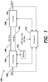
- FIG. 1 is a block diagram of an online UPS 100 according to one aspect of the present invention.
- the UPS 100 includes an input 102, a converter 104, a positive DC bus 106, a negative DC bus 107, an inverter 108, an output 110, and a controller 114.
- the input 102 is coupled to the converter 104.
- the positive DC bus 106 and the negative DC bus 107 are coupled between the converter 104 and the inverter 108.
- the output 110 is coupled to the inverter 108.
- the controller 114 is coupled to the input 102, the output 110, the converter 104, the positive DC bus 106, the negative DC bus 107, and the inverter 108.
- the converter 104 is also configured to be coupled to a battery 112.
- the input 102 is configured to be coupled to an AC mains power source and to receive input AC power having an input voltage level.
- the controller 114 monitors the input AC power received by the input 102 and is configured to operate the UPS 100 in different modes of operation based on the status of the input AC power received by the input 102.
- the controller 114 operates the UPS 100 in an online mode of operation. In the online mode of operation, AC power from the input 102 is provided to the converter 104.
- the converter 104 is a Power Factor Correction converter 104; however, in other embodiments, other types of converters may be utilized.
- the controller 114 operates the converter 104 to convert the AC power into DC power and provide the DC power to the positive DC bus 106 and the negative DC bus 107.
- DC power is also provided from the converter 104 to the battery 112 to charge the battery 112.
- DC power from the positive DC bus 106 and the negative DC bus 107 is provided to the battery 112 via a DC/DC converter to charge the battery 112.
- the inverter 108 receives DC power from the positive DC bus 106 and the negative DC bus 107, and the controller 114 operates the inverter 108 to convert the DC power into regulated AC power and provide regulated AC power to a load coupled to the output 110.
- the controller 114 When AC power provided to the input 102 is not acceptable (i.e., below an input power threshold), the controller 114 operates the UPS 100 in a backup mode of operation. In the backup mode of operation, DC power from the battery 112 is regulated (e.g., by the converter 104) and provided to the positive DC bus 106 and the negative DC bus 107.
- the inverter 108 receives the DC power from the positive DC bus 106 and the negative DC bus 107, and the controller 114 operates the inverter 108 to convert the DC power into regulated AC power and provide the regulated AC power to the output 110.
- FIG. 2 is a schematic diagram illustrating one embodiment of the converter 104.
- the converter 104 includes an input line 202, a neutral line 204, an input switch 206, a battery circuit 208, and a PFC stage 209.
- the PFC stage 209 includes an interface 203, an inductor 210, a first switch (Q1) 212, a second switch (Q2) 214, a third switch (Q3) 216, a fourth switch (Q4) 218, a first bus capacitor 220, and a second bus capacitor 222.
- the battery circuit 208 includes a fifth switch (Q5) 226, a sixth switch (Q6) 228, a seventh switch (Q7) 230, and an eight switch (Q8) 232.
- the switches (Q1-Q8) 212-232 are Gallium Nitride (GaN) Field-Effect Transistors; however, in other embodiments, different types of switches or transistors can be utilized.
- the switches (Q1-Q8) 212-232 are Metal-Oxide-Semiconductor Field-Effect Transistors (MOSFET).
- MOSFET Metal-Oxide-Semiconductor Field-Effect Transistors
- thyristors can be used for switches Q5-Q8 226-232.
- each switch (Q1-Q8) 212-232 includes a built-in body diode coupled between the drain and the source. The body diodes 227 of switches Q5-Q8 226-232 are shown in FIG. 2 , while the body diodes of switches Q1-Q4 212-218 are not shown for illustrative purposes.
- the input line 202 and the neutral line 204 are configured to be coupled to an input power source (e.g., mains) via the input 102.
- the neutral line 204 is coupled to ground 224.
- the input switch 206 is configurable to selectively couple either the input line 202 or the battery circuit 208 to the interface 203.
- the interface 203 is coupled to a first end of the inductor 210.
- the second end of the inductor 210 is coupled to the drain of the first switch (Q1) 212.
- the source of the first switch (Q1) 212 is coupled to the source of the second switch (Q2) 214.
- the drain of the second switch (Q2) 214 is coupled to the neutral line 204.
- the second end of the inductor 210 is also coupled to the source of the third switch (Q3) 216 and the drain of the fourth switch (Q4) 218.
- the drain of the third switch (Q3) 216 is coupled to the positive DC bus 106.
- the source of the fourth switch (Q4) 218 is coupled to the negative DC bus 107.
- the first bus capacitor 220 is coupled between the positive DC bus 106 and the neutral line 204.
- the second bus capacitor 222 is coupled between the negative DC bus 107 and the neutral line 204.
- the drain of the fifth switch (Q5) 226 and the source of the seventh switch (Q7) 230 are coupled to the input switch 206.
- the source of the fifth switch (Q5) 226 is configured to be coupled to a negative terminal 111 of the battery 112.
- the drain of the seventh switch (Q7) 230 is configured to be coupled to a positive terminal 113 of the battery 112.
- the source of the sixth switch (Q6) 228 is configured to be coupled to the negative terminal 111 of the battery 112.
- the drain of the eight switch (Q8) 232 is configured to be coupled to the positive terminal 113 of the battery 112.
- the drain of the sixth switch (Q6) 228 and the source of the eighth switch (Q8) are coupled to the neutral line 204.
- the controller 114 is coupled to the gate of each switch (Q1-Q8) 212-232 and the input switch 206 and is configured to transmit control signals to (i.e., control operation of) each switch (Q1-Q8) 212-232 and the input switch 206).
- the controller 114 monitors the input AC power received by the input 102 and is configured to operate the UPS 100 in different modes of operation based on the status of the input AC power received by the input 102.
- the controller 114 operates the UPS 100 in the online mode of operation.
- the controller 114 operates the input switch 206 to couple the input line 202 to the inductor 210 via the interface 203.
- the controller 114 When the input line 202 is coupled to the inductor 210, the controller 114 operates the first switch (Q1) 212, second switch (Q2) 214, third switch (Q3) 216, and fourth switch (Q4) 218, in conjunction with the inductor 210 and the bus capacitors 220, 222, to generate a positive output DC voltage on the positive DC bus 106 and a negative output DC voltage on the negative DC bus 107. In at least one embodiment, the controller 114 also operates the first switch (Q1) 212, second switch (Q2) 214, third switch (Q3) 216, and fourth switch (Q4) 218 to provide Power Factor Correction (PFC).
- PFC Power Factor Correction
- FIG. 3 is a schematic diagram of a first stage of the backup mode of operation where a positive DC voltage is generated on the positive DC bus 106
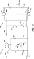
- FIG. 4 is a schematic diagram of a second stage of the backup mode of operation where a negative DC voltage is generated on the negative DC bus 107.
- the controller 114 operates the input switch 206 to couple the battery circuit 208 to the inductor 210 via the interface 203. Also during the first stage of the backup mode of operation, the controller 114 operates the converter 104 to couple the positive terminal 113 of the battery 112 to the inductor 210 and the negative terminal 111 of the battery 112 to the neutral line 204. For example, in at least one embodiment, the controller 114 operates the sixth switch (Q6) 228 to close, coupling the positive terminal 113 to the inductor 210 (via the input switch 206 and the interface 203), and the seventh switch (Q7) 230 to close, coupling the negative terminal 111 to the neutral line 204. Closed switches Q6 228 and Q7 230 are shown in FIG. 3 as resulting direct connections.
- the controller 114 operates the first switch (Q1) 212, the second switch (Q2) 214, and the third switch (Q3) 216 as a boost converter to charge the bus capacitor 220 coupled to the positive DC bus 106 (i.e., generate a positive DC voltage on the positive DC bus 106).
- the controller 114 alternates switching of the first switch (Q1) 212, the second switch (Q2) 214, and the third switch (Q3) 216 to generate the desired positive voltage level on the positive DC bus 106.
- the first switch (Q1) 212 and the second switch (Q2) 214 are closed, the current path 302 passes from the inductor 210 to the neutral line 204, via the first switch (Q1) 212, and the second switch (Q2) 214, energy is stored in the inductor 210, and the current through the inductor 210 increases.
- the first switch (Q1) 212 and the second switch 214 are subsequently opened, a resulting current path from the inductor 210 to the positive DC bus 106, via the body diode of the third switch (Q3), 216 is generated.
- the third switch (Q3) 216 can subsequently be operated to close by the controller 114. By operating the switches as described above, the desired positive DC voltage level can be generated on the positive DC bus 106.
- the controller 114 operates the input switch 206 to couple the battery circuit 208 to the inductor 210 via the interface 203. Also during the second stage of the backup mode of operation, the controller 114 operates the converter 104 to couple the negative terminal 111 of the battery 112 to the inductor 210 and the positive terminal 113 of the battery 112 to the neutral line 204. For example, in at least one embodiment, the controller 114 operates the fifth switch (Q5) 226 to close, coupling the negative terminal 111 to the inductor 210 (via the input switch 206 and the interface 203), and the eighth switch (Q8) 233 to close, coupling the positive terminal 113 to the neutral line 204. Closed switches Q5 226 and Q8 232 are shown in FIG. 4 as resulting direct connections.
- the body diodes 227 of the sixth switch (Q6) 228 and the seventh switch (Q7) 230 are reverse biased and a current path 402, shown in FIG. 4 , is generated.
- the controller 114 operates the first switch (Q1) 212, the second switch (Q2) 214, and the fourth switch (Q4) 218 as a boost converter to charge the second bus capacitor 222 coupled to the negative DC bus 107 (i.e., generate a negative DC voltage on the positive DC bus 107).
- the controller 114 alternates switching of the first switch (Q1) 212, the second switch (Q2) 214, and the fourth switch (Q4) 218 to generate the desired negative voltage level on the negative DC bus 107.
- the first switch (Q1) 212 and the second switch (Q2) 214 are closed, the current path 402 passes from the neutral line 204 to the inductor 210, via the second switch (Q2) 214 and the first switch (Q1) 212, energy is stored in the inductor 210, and current through the inductor 210 increases (in a direction opposite to that during the first stage of the backup mode of operation).
- the first switch (Q1) 212 and the second switch 214 are subsequently opened, a resulting current path from the negative DC bus 107 to the inductor 210, via the body diode of the fourth switch (Q4) 218, is generated.
- the fourth switch (Q4) 218 can subsequently be operated to close by the controller 114. By operating the switches as described above, the desired negative DC voltage level can be generated on the negative DC bus 107.
- the converter 104 in the backup mode of operation, the converter 104 generates a positive DC voltage on the positive DC bus 106 (during the first stage of the backup mode of operation) and a negative DC voltage no the negative DC bus 107 (during the second stage of the backup mode of operation).
- the controller 114 synchronizes the operation of the converter 104 in the backup mode of operation with the operation of the inverter 108 coupled to the DC busses 106, 107.
- the controller 114 can synchronize the first stage of the backup mode of operation (i.e., when the positive terminal 113 of the battery 112 is coupled to the inductor 210 and the converter operates to generate a positive DC voltage on the positive DC bus 106) with a positive half cycle of an output waveform provided by the inverter 108 to the output 110.
- the controller 114 can further synchronize the second stage of the backup mode of operation (i.e., when the negative terminal 113 of the battery 112 is coupled to the inductor 210 and the converter operates to generate a negative DC voltage on the negative DC bus 106) with a negative half cycle of the output waveform provided by the inverter 108 to the output 110.
- the controller 114 is configured to monitor and control operation of the UPS 100. Using data stored in associated memory, the controller 114 is operable to execute one or more instructions that may result in the manipulation of one or more switches' conductive states.
- the controller 114 can include one or more processors or other types of controllers.
- the controller 114 may perform a portion of the functions discussed herein on a processor, and perform another portion using an Application-Specific Integrated Circuit (ASIC) tailored to perform particular operations. Examples in accordance with the present invention may perform the operations described herein using many specific combinations of hardware and software and the invention is not limited to any particular combination of hardware and software components.
- ASIC Application-Specific Integrated Circuit
- the PFC converter 104 is utilized in a single-phase UPS 100.
- the PFC converter 104 can be utilized with any other type of single phase online UPS with positive and negative DC busses.
- the PFC converter 104 is utilized in a 120V (RMS value) UPS system with a 120V (nominal) battery. In such a system, the DC voltage level on the DC busses is regulated to be around 200V.
- the PFC converter 104 is utilized in a 230V (RMS value) UPS system with a 192V (nominal) battery. In such a system, the DC voltage level on the DC busses is regulated to be around 400V.
- the converter can also be utilized in a higher power UPS with three phase inputs.
- FIG. 5 is a schematic diagram of a converter 500 utilized in a three phase UPS.
- the converter 500 includes multiple inputs 502a-c (e.g., each configured to be coupled to one phase of a three-phase power source), a battery circuit 504 (e.g., such as the battery circuit 208 shown in FIG. 2 ), and a Vienna rectifier 506.
- An input switch 503a-c is configured to selectively couple the Vienna rectifier 506 to either a corresponding input 502a-c or the battery circuit 504.
- the Vienna rectifier 506 includes Silicon Carbide (SiC) diodes 508 and MOSFETs 510; however, in other embodiments, the Vienna rectifier 506 is configured differently.
- the converter 500 shown in FIG. 5 is operated in substantially the same way as the converter 103 described above with respect to FIGS. 2-4 , except that it generates the regulated DC output from all three phase inputs, rather than one single phase input.
- the PFC converter can be reused in a UPS to convert DC power from the battery 112 to regulated DC power.
- the converter described above can be operated with relatively low losses/high efficiency.
- switches Q5-Q8 226-232 since switches Q5-Q8 226-232 operate at line frequency and only switch the battery voltage, lower voltage switches (e.g., lower voltage MOSFETs) can be utilized as switches Q5-Q8 226-232.
- the switches (Q1-Q8) 212-232 are GaN FETs and/or Metal-Oxide-Semiconductor Field-Effect Transistors; however, in other embodiments, different types of switches or transistors can be utilized.
- the third switch (Q3) 216 and the fourth switch (Q4) 218 are switches or transistors; however, in at least on embodiment, the third switch (Q3) 216 and the fourth switch (Q4) 218 can be replaced by diodes.
- the battery circuit 208 is coupled to a dual DC bus PFC stage with AC switches (e.g., as shown in FIG. 2 ); however, in other embodiments, the battery circuit 208 can be coupled to a different type of PFC stage.
- the battery circuit (e.g., shown in FIG. 2 ) includes a fuse in series with each switch Q5-Q8 226-232 in case of switch failure.
Landscapes
- Engineering & Computer Science (AREA)
- Power Engineering (AREA)
- Business, Economics & Management (AREA)
- Emergency Management (AREA)
- Rectifiers (AREA)
- Dc-Dc Converters (AREA)
- Charge And Discharge Circuits For Batteries Or The Like (AREA)
Applications Claiming Priority (1)
| Application Number | Priority Date | Filing Date | Title |
|---|---|---|---|
| US16/206,027 US10944319B2 (en) | 2018-11-30 | 2018-11-30 | Flying battery with AC switch PFC front end for ups |
Publications (1)
| Publication Number | Publication Date |
|---|---|
| EP3661008A1 true EP3661008A1 (de) | 2020-06-03 |
Family
ID=68581662
Family Applications (1)
| Application Number | Title | Priority Date | Filing Date |
|---|---|---|---|
| EP19209278.1A Pending EP3661008A1 (de) | 2018-11-30 | 2019-11-14 | Fliegende batterie mit wechselstromschalter-pfc-frontend für usv |
Country Status (3)
| Country | Link |
|---|---|
| US (1) | US10944319B2 (de) |
| EP (1) | EP3661008A1 (de) |
| CN (2) | CN120638598A (de) |
Cited By (2)
| Publication number | Priority date | Publication date | Assignee | Title |
|---|---|---|---|---|
| EP4012908A1 (de) * | 2020-12-09 | 2022-06-15 | Schneider Electric IT Corporation | Integrierter pfc- und gleichspannungswandler für einen doppelgleichstrom-bus zur online-usv-anwendung |
| CN115483751A (zh) * | 2021-06-15 | 2022-12-16 | 施耐德电气It公司 | 用于在线ups系统的具有集成充电器和dc-dc的ac开关pfc |
Families Citing this family (1)
| Publication number | Priority date | Publication date | Assignee | Title |
|---|---|---|---|---|
| US20200176998A1 (en) * | 2018-12-03 | 2020-06-04 | Omnitek Partners Llc | Methods for heating and charging energy storage devices at very low temperatures |
Citations (3)
| Publication number | Priority date | Publication date | Assignee | Title |
|---|---|---|---|---|
| US6266260B1 (en) * | 1999-09-03 | 2001-07-24 | Powerware Corporation | Inverter having center switch and uninterruptible power supply implementing same |
| US20130027126A1 (en) * | 2011-07-28 | 2013-01-31 | American Power Conversion Corporation | Dual boost converter for ups system |
| EP2751919A1 (de) * | 2011-08-29 | 2014-07-09 | Schneider Electric IT Corporation | Doppelhochsetzteller mit integrierter ladevorrichtung für eine usv |
Family Cites Families (9)
| Publication number | Priority date | Publication date | Assignee | Title |
|---|---|---|---|---|
| AT406434B (de) | 1993-12-23 | 2000-05-25 | Ixys Semiconductor Gmbh | Vorrichtung zur umformung eines dreiphasigen spannungssystems in eine vorgebbare, einen verbraucher speisende gleichspannung |
| US6181029B1 (en) * | 1998-11-06 | 2001-01-30 | International Business Machines Corporation | Method of controlling battery back-up for multiple power supplies |
| US7615891B2 (en) * | 2007-12-19 | 2009-11-10 | American Power Conversion Corporation | Systems for and methods of controlling operation of a UPS |
| US9300220B2 (en) * | 2013-05-29 | 2016-03-29 | Voltronic Power Technology Corp. | Uninterruptible power supply system |
| CN103715921B (zh) * | 2013-12-19 | 2015-10-28 | 浙江大学 | 用于vienna整流器的限流控制方法 |
| US9973097B2 (en) * | 2016-06-21 | 2018-05-15 | Astronics Advanced Electronic Systems Corp. | Regulating transformer rectifier unit with multiple circuits for preventing output overvoltage |
| US10461575B2 (en) * | 2017-03-28 | 2019-10-29 | Schneider Electric It Corporation | Multistate PWM command for 3 levels inverters |
| TWI658678B (zh) * | 2017-12-25 | 2019-05-01 | 台達電子工業股份有限公司 | 不斷電電源供應裝置 |
| CN107896069B (zh) * | 2017-12-25 | 2020-02-14 | 三峡大学 | 一种新型单相混合三电平整流器 |
-
2018
- 2018-11-30 US US16/206,027 patent/US10944319B2/en active Active
-
2019
- 2019-11-14 EP EP19209278.1A patent/EP3661008A1/de active Pending
- 2019-11-29 CN CN202510797538.8A patent/CN120638598A/zh active Pending
- 2019-11-29 CN CN201911203552.1A patent/CN111262331B/zh active Active
Patent Citations (3)
| Publication number | Priority date | Publication date | Assignee | Title |
|---|---|---|---|---|
| US6266260B1 (en) * | 1999-09-03 | 2001-07-24 | Powerware Corporation | Inverter having center switch and uninterruptible power supply implementing same |
| US20130027126A1 (en) * | 2011-07-28 | 2013-01-31 | American Power Conversion Corporation | Dual boost converter for ups system |
| EP2751919A1 (de) * | 2011-08-29 | 2014-07-09 | Schneider Electric IT Corporation | Doppelhochsetzteller mit integrierter ladevorrichtung für eine usv |
Cited By (7)
| Publication number | Priority date | Publication date | Assignee | Title |
|---|---|---|---|---|
| EP4012908A1 (de) * | 2020-12-09 | 2022-06-15 | Schneider Electric IT Corporation | Integrierter pfc- und gleichspannungswandler für einen doppelgleichstrom-bus zur online-usv-anwendung |
| US11705753B2 (en) | 2020-12-09 | 2023-07-18 | Schneider Electric It Corporation | Integrated PFC and DC DC converter for dual DC bus for online UPS application |
| US12003135B2 (en) | 2020-12-09 | 2024-06-04 | Schneider Electric It Corporation | Integrated PFC and DC DC converter for dual DC bus for online UPS application |
| CN115483751A (zh) * | 2021-06-15 | 2022-12-16 | 施耐德电气It公司 | 用于在线ups系统的具有集成充电器和dc-dc的ac开关pfc |
| EP4106163A1 (de) * | 2021-06-15 | 2022-12-21 | Schneider Electric IT Corporation | Wechselstromschalter-pfc mit integriertem ladegerät und gleichstrom-gleichstrom für online-ups-systeme |
| US11777338B2 (en) | 2021-06-15 | 2023-10-03 | Schneider Electric It Corporation | AC switch PFC with integrated charger and DC-DC for online UPS systems |
| US12062943B2 (en) | 2021-06-15 | 2024-08-13 | Schneider Electric It Corporation | AC switch PFC with integrated charger and DC-DC for online UPS systems |
Also Published As
| Publication number | Publication date |
|---|---|
| US20200177074A1 (en) | 2020-06-04 |
| CN111262331A (zh) | 2020-06-09 |
| CN111262331B (zh) | 2025-07-11 |
| US10944319B2 (en) | 2021-03-09 |
| CN120638598A (zh) | 2025-09-12 |
Similar Documents
| Publication | Publication Date | Title |
|---|---|---|
| CN103828185B (zh) | 用于ups系统的双升压转换器 | |
| AU2012302148B2 (en) | Twin boost converter with integrated charger for ups | |
| US11157430B2 (en) | DC-DC power converter with four way power conversion | |
| US11283288B2 (en) | Integrated DC to DC converter UPS topology | |
| EP1872453A2 (de) | Verfahren und vorrichtung zur bereitstellung einer ununterbrechbaren stromversorgung | |
| EP3185393B1 (de) | Usv mit integriertem überbrückungsschalter | |
| US12003135B2 (en) | Integrated PFC and DC DC converter for dual DC bus for online UPS application | |
| US11777338B2 (en) | AC switch PFC with integrated charger and DC-DC for online UPS systems | |
| CN106664027A (zh) | 供电控制 | |
| EP3661008A1 (de) | Fliegende batterie mit wechselstromschalter-pfc-frontend für usv | |
| EP3480934B1 (de) | Bidirektionaler dc-ac-wandler mit zwei richtungen | |
| CN110957900A (zh) | 降低功率转换器中的过冲的箝位电路 | |
| US11387670B2 (en) | Double conversion on line ups with pass through neutral employing single DC bus | |
| EP3661010A1 (de) | System und verfahren zur reduzierung der emv-abstrahlung in einem stromwandler | |
| EP3609070B1 (de) | Hocheffizienter flexibler wandler | |
| US10211750B2 (en) | Apparatus and method for low frequency power inverter | |
| EP3661011B1 (de) | 3-phasen-usv-busausgleicher |
Legal Events
| Date | Code | Title | Description |
|---|---|---|---|
| PUAI | Public reference made under article 153(3) epc to a published international application that has entered the european phase |
Free format text: ORIGINAL CODE: 0009012 |
|
| STAA | Information on the status of an ep patent application or granted ep patent |
Free format text: STATUS: THE APPLICATION HAS BEEN PUBLISHED |
|
| AK | Designated contracting states |
Kind code of ref document: A1 Designated state(s): AL AT BE BG CH CY CZ DE DK EE ES FI FR GB GR HR HU IE IS IT LI LT LU LV MC MK MT NL NO PL PT RO RS SE SI SK SM TR |
|
| AX | Request for extension of the european patent |
Extension state: BA ME |
|
| STAA | Information on the status of an ep patent application or granted ep patent |
Free format text: STATUS: REQUEST FOR EXAMINATION WAS MADE |
|
| 17P | Request for examination filed |
Effective date: 20201203 |
|
| RBV | Designated contracting states (corrected) |
Designated state(s): AL AT BE BG CH CY CZ DE DK EE ES FI FR GB GR HR HU IE IS IT LI LT LU LV MC MK MT NL NO PL PT RO RS SE SI SK SM TR |
|
| STAA | Information on the status of an ep patent application or granted ep patent |
Free format text: STATUS: EXAMINATION IS IN PROGRESS |
|
| 17Q | First examination report despatched |
Effective date: 20220222 |