EP3661132B1 - Fahrzeugmontierte relaisvorrichtung, fahrzeugmontierte überwachungsvorrichtung, fahrzeugmontiertes steuernetzwerksystem, kommunikationsüberwachungsverfahren und programm - Google Patents
Fahrzeugmontierte relaisvorrichtung, fahrzeugmontierte überwachungsvorrichtung, fahrzeugmontiertes steuernetzwerksystem, kommunikationsüberwachungsverfahren und programm Download PDFInfo
- Publication number
- EP3661132B1 EP3661132B1 EP18838223.8A EP18838223A EP3661132B1 EP 3661132 B1 EP3661132 B1 EP 3661132B1 EP 18838223 A EP18838223 A EP 18838223A EP 3661132 B1 EP3661132 B1 EP 3661132B1
- Authority
- EP
- European Patent Office
- Prior art keywords
- control
- vehicle
- determination
- network
- data
- Prior art date
- Legal status (The legal status is an assumption and is not a legal conclusion. Google has not performed a legal analysis and makes no representation as to the accuracy of the status listed.)
- Active
Links
Images





Classifications
-
- H—ELECTRICITY
- H04—ELECTRIC COMMUNICATION TECHNIQUE
- H04L—TRANSMISSION OF DIGITAL INFORMATION, e.g. TELEGRAPHIC COMMUNICATION
- H04L12/00—Data switching networks
- H04L12/28—Data switching networks characterised by path configuration, e.g. LAN [Local Area Networks] or WAN [Wide Area Networks]
- H04L12/40—Bus networks
- H04L12/40169—Flexible bus arrangements
- H04L12/40176—Flexible bus arrangements involving redundancy
- H04L12/40182—Flexible bus arrangements involving redundancy by using a plurality of communication lines
-
- G—PHYSICS
- G07—CHECKING-DEVICES
- G07C—TIME OR ATTENDANCE REGISTERS; REGISTERING OR INDICATING THE WORKING OF MACHINES; GENERATING RANDOM NUMBERS; VOTING OR LOTTERY APPARATUS; ARRANGEMENTS, SYSTEMS OR APPARATUS FOR CHECKING NOT PROVIDED FOR ELSEWHERE
- G07C5/00—Registering or indicating the working of vehicles
- G07C5/008—Registering or indicating the working of vehicles communicating information to a remotely located station
-
- H—ELECTRICITY
- H04—ELECTRIC COMMUNICATION TECHNIQUE
- H04L—TRANSMISSION OF DIGITAL INFORMATION, e.g. TELEGRAPHIC COMMUNICATION
- H04L12/00—Data switching networks
- H04L12/28—Data switching networks characterised by path configuration, e.g. LAN [Local Area Networks] or WAN [Wide Area Networks]
-
- H—ELECTRICITY
- H04—ELECTRIC COMMUNICATION TECHNIQUE
- H04L—TRANSMISSION OF DIGITAL INFORMATION, e.g. TELEGRAPHIC COMMUNICATION
- H04L12/00—Data switching networks
- H04L12/28—Data switching networks characterised by path configuration, e.g. LAN [Local Area Networks] or WAN [Wide Area Networks]
- H04L12/40—Bus networks
- H04L12/40006—Architecture of a communication node
- H04L12/40013—Details regarding a bus controller
-
- H—ELECTRICITY
- H04—ELECTRIC COMMUNICATION TECHNIQUE
- H04L—TRANSMISSION OF DIGITAL INFORMATION, e.g. TELEGRAPHIC COMMUNICATION
- H04L12/00—Data switching networks
- H04L12/28—Data switching networks characterised by path configuration, e.g. LAN [Local Area Networks] or WAN [Wide Area Networks]
- H04L12/46—Interconnection of networks
-
- H—ELECTRICITY
- H04—ELECTRIC COMMUNICATION TECHNIQUE
- H04L—TRANSMISSION OF DIGITAL INFORMATION, e.g. TELEGRAPHIC COMMUNICATION
- H04L12/00—Data switching networks
- H04L12/28—Data switching networks characterised by path configuration, e.g. LAN [Local Area Networks] or WAN [Wide Area Networks]
- H04L12/46—Interconnection of networks
- H04L12/4604—LAN interconnection over a backbone network, e.g. Internet, Frame Relay
- H04L12/462—LAN interconnection over a bridge based backbone
- H04L12/4625—Single bridge functionality, e.g. connection of two networks over a single bridge
-
- H—ELECTRICITY
- H04—ELECTRIC COMMUNICATION TECHNIQUE
- H04L—TRANSMISSION OF DIGITAL INFORMATION, e.g. TELEGRAPHIC COMMUNICATION
- H04L12/00—Data switching networks
- H04L12/28—Data switching networks characterised by path configuration, e.g. LAN [Local Area Networks] or WAN [Wide Area Networks]
- H04L12/46—Interconnection of networks
- H04L12/4633—Interconnection of networks using encapsulation techniques, e.g. tunneling
-
- H—ELECTRICITY
- H04—ELECTRIC COMMUNICATION TECHNIQUE
- H04L—TRANSMISSION OF DIGITAL INFORMATION, e.g. TELEGRAPHIC COMMUNICATION
- H04L67/00—Network arrangements or protocols for supporting network services or applications
- H04L67/01—Protocols
- H04L67/02—Protocols based on web technology, e.g. hypertext transfer protocol [HTTP]
- H04L67/025—Protocols based on web technology, e.g. hypertext transfer protocol [HTTP] for remote control or remote monitoring of applications
-
- H—ELECTRICITY
- H04—ELECTRIC COMMUNICATION TECHNIQUE
- H04L—TRANSMISSION OF DIGITAL INFORMATION, e.g. TELEGRAPHIC COMMUNICATION
- H04L67/00—Network arrangements or protocols for supporting network services or applications
- H04L67/01—Protocols
- H04L67/12—Protocols specially adapted for proprietary or special-purpose networking environments, e.g. medical networks, sensor networks, networks in vehicles or remote metering networks
-
- H—ELECTRICITY
- H04—ELECTRIC COMMUNICATION TECHNIQUE
- H04L—TRANSMISSION OF DIGITAL INFORMATION, e.g. TELEGRAPHIC COMMUNICATION
- H04L67/00—Network arrangements or protocols for supporting network services or applications
- H04L67/50—Network services
- H04L67/535—Tracking the activity of the user
-
- H—ELECTRICITY
- H04—ELECTRIC COMMUNICATION TECHNIQUE
- H04L—TRANSMISSION OF DIGITAL INFORMATION, e.g. TELEGRAPHIC COMMUNICATION
- H04L67/00—Network arrangements or protocols for supporting network services or applications
- H04L67/50—Network services
- H04L67/56—Provisioning of proxy services
- H04L67/565—Conversion or adaptation of application format or content
-
- H—ELECTRICITY
- H04—ELECTRIC COMMUNICATION TECHNIQUE
- H04W—WIRELESS COMMUNICATION NETWORKS
- H04W4/00—Services specially adapted for wireless communication networks; Facilities therefor
- H04W4/30—Services specially adapted for particular environments, situations or purposes
- H04W4/40—Services specially adapted for particular environments, situations or purposes for vehicles, e.g. vehicle-to-pedestrians [V2P]
-
- H—ELECTRICITY
- H04—ELECTRIC COMMUNICATION TECHNIQUE
- H04W—WIRELESS COMMUNICATION NETWORKS
- H04W88/00—Devices specially adapted for wireless communication networks, e.g. terminals, base stations or access point devices
- H04W88/16—Gateway arrangements
-
- H—ELECTRICITY
- H04—ELECTRIC COMMUNICATION TECHNIQUE
- H04W—WIRELESS COMMUNICATION NETWORKS
- H04W92/00—Interfaces specially adapted for wireless communication networks
- H04W92/02—Inter-networking arrangements
-
- H—ELECTRICITY
- H04—ELECTRIC COMMUNICATION TECHNIQUE
- H04L—TRANSMISSION OF DIGITAL INFORMATION, e.g. TELEGRAPHIC COMMUNICATION
- H04L12/00—Data switching networks
- H04L12/28—Data switching networks characterised by path configuration, e.g. LAN [Local Area Networks] or WAN [Wide Area Networks]
- H04L12/40—Bus networks
- H04L2012/40208—Bus networks characterized by the use of a particular bus standard
- H04L2012/40215—Controller Area Network CAN
-
- H—ELECTRICITY
- H04—ELECTRIC COMMUNICATION TECHNIQUE
- H04L—TRANSMISSION OF DIGITAL INFORMATION, e.g. TELEGRAPHIC COMMUNICATION
- H04L12/00—Data switching networks
- H04L12/28—Data switching networks characterised by path configuration, e.g. LAN [Local Area Networks] or WAN [Wide Area Networks]
- H04L12/40—Bus networks
- H04L2012/40267—Bus for use in transportation systems
- H04L2012/40273—Bus for use in transportation systems the transportation system being a vehicle
-
- H—ELECTRICITY
- H04—ELECTRIC COMMUNICATION TECHNIQUE
- H04L—TRANSMISSION OF DIGITAL INFORMATION, e.g. TELEGRAPHIC COMMUNICATION
- H04L69/00—Network arrangements, protocols or services independent of the application payload and not provided for in the other groups of this subclass
- H04L69/08—Protocols for interworking; Protocol conversion
- H04L69/085—Protocols for interworking; Protocol conversion specially adapted for interworking of IP-based networks with other networks
Definitions
- the present disclosure relates to a relay device or the like that relays communication between a plurality of control networks in an in-vehicle network.
- CAN Controller Area Network
- existing security countermeasure technologies for the in-vehicle network of the CAN include a technique for detecting anomaly by receiving periodically sent data frames and matching the transmission period against a predetermined rule regarding a transmission period (refer to, for example, PTL 1).
- Ethernet registered trademark
- Ethernet provides the data size per transaction that is much larger than that in CAN. Accordingly, a technique has been developed for putting together data corresponding to a plurality of CAN frames into an Ethernet frame in accordance with the order of transmission/reception of the data and transmitting the data (refer to, for example, PTL 2).
- PTL 3 relates to a system and method for providing security to a network which may include maintaining, by a processor, a timing model of an expected behavior of data communications over the in-vehicle communication network; receiving, by the processor, a message sent over the network; determining, by the controller, based on the model and based on a timing attribute of the message, whether or not the message complies with the model; and if the message does not comply with the model then performing, by the processor, at least one action related to the message.
- PTL 4 relates to a vehicle-mounted relay device, a vehicle-mounted communication system and a relay program with which it is possible to prevent unauthorized messages from being relayed between networks.
- a vehicle-mounted relay device having a plurality of communication units to which a plurality of CAN buses are connected determines whether or not messages transmitted by ECUs connected to the CAN buses are authorized. If a message is determined to be unauthorized, the vehicle-mounted relay device notifies the CAN buses connected to the communication unit that received the message that an unauthorized message has been transmitted. The vehicle-mounted relay device prohibits subsequent relaying of messages having the same CAN-ID as the CAN-ID included in the message determined to be unauthorized. At this time the vehicle-mounted relay device notifies communication lines connected to communication units other than the communication unit that received the message determined to be unauthorized that relaying of messages has been prohibited.
- PTL 5 relates to a fraud-detection method for use in an in-vehicle network system including a plurality of electronic control units (ECUs) that exchange messages on a bus and a fraud-detection ECU connected to the bus, the fraud-detection ECU includes a memory that stores rule information indicating a rule regarding transmission of a message to be transmitted on the bus, the fraud-detection ECU determines whether or not a message transmitted on the bus is malicious by using the rule information, and, in a case where the message is malicious, transmits an error message including a message identifier of the malicious message.
- the fraud-detection ECU acquires updated rule information transmitted from an external server, and updates the rule information by using the updated rule information.
- the above-described existing configuration has a first problem in that if an in-vehicle network includes a CAN control network and an Ethernet control network, anomaly determination using the transmission periodicity lacks reliability, since the configuration of the Ethernet network is not of a bus type.
- a single Ethernet frame including control data corresponding to a plurality of CAN frames does not always include a series of CAN control commands to be processed continuously or in a short time. For this reason, a series of control commands may be set in a plurality of different Ethernet frames and may be transmitted separately. At this time, according to Ethernet, delivery of a frame may fail, and the undelivered frame is retransmitted. However, when the undelivered frame is retransmitted, a second problem occurs.
- a control device (hereinafter also referred to as an "ECU (Electronic Control Unit)" connected to the CAN network may not correctly control the vehicle due to the occurrence of mismatch between the order in which a plurality of control commands are processed and the order in which the control commands are received or due to a situation in which a plurality of control commands to be processed within a certain period of time are not received within the certain period of time.
- ECU Electronic Control Unit
- the present disclosure provides an in-vehicle relay device capable of making a more reliable anomaly determination on a frame including a plurality of control commands by using a method that does not require use of a transmission period and preventing the occurrence of an anomaly of a control command transmitted and received over control networks having different data sizes transmittable in one frame.
- an in-vehicle relay device that solves the above-described problems.
- the in-vehicle relay device relays communication between a plurality of control devices in a vehicle over a plurality of networks to which the plurality of control devices are connected.
- the in-vehicle relay device includes a communication unit that receives control data from a first control network included in the plurality of networks, where the control data includes, in a frame, a plurality of control commands to be executed by at least some of the control devices, and a determination unit that makes a first determination as to whether types of the control commands included in the frame form a first combination preset as a combination of control commands executable simultaneously and thereafter makes a second determination as to whether the control data is anomalous by using a result of the first determination, and outputs a result of the second determination.
- an in-vehicle monitoring device that solves the above-described problem.
- the in-vehicle monitoring device is included in an in-vehicle network having a first control network and a second control network between which communication is relayed by a relay device and is connected to the first control network.
- the in-vehicle monitoring device includes a communication unit that receives control data transmitted from a control device connected to the first control network, where the control data includes, in a frame, a plurality of control commands for control to be performed by a control device connected to the second control network, and a determination unit that makes a first determination as to whether types of the control commands included in the frame form a first combination preset as a combination of control commands executable simultaneously and thereafter makes a second determination as to whether the control data is anomalous by using a result of the first determination and outputs a result of the second determination.
- the largest data size of the control command transmittable in one frame is larger than the largest data size of the control command transmittable in one frame in the second control network.
- a communication monitoring method for use of an in-vehicle relay device that relays communication between a plurality of control devices in a vehicle over a plurality of networks to which the plurality of control devices are connected.
- the in-vehicle relay device includes a communication unit and a processor.
- the method includes receiving, by using the communication unit, control data from a first control network included in the plurality of networks, where the control data includes, in a frame, a plurality of control commands to be executed by at least some of the control devices, and making, by using the processor, a first determination as to whether types of the control commands included in the frame form a first combination preset as a combination of control commands executable simultaneously and thereafter making a second determination as to whether the control data is anomalous by using a result of the first determination, and outputting a result of the second determination.
- a program for use in an in-vehicle relay device that relays communication between a plurality of control devices in a vehicle over a plurality of networks to which the plurality of control devices are connected.
- the in-vehicle relay device includes a communication unit and a processor.
- the program includes a program code executing a method, when the program is executed by the processor.
- the method includes receiving, by using the communication unit, control data from a first control network included in the plurality of networks, where the control data includes, in a frame, a plurality of control commands to be executed by at least some of the control devices, and making, by using the processor, a first determination as to whether types of the control commands included in the frame form a first combination preset as a combination of control commands executable simultaneously and thereafter making a second determination as to whether the control data is anomalous by using a result of the first determination, and outputting a result of the second determination.
- an in-vehicle control network system includes a first control network and a second control network having a plurality of control devices connected thereto, where communication between the control devices is relayed by an in-vehicle relay device.
- the largest data size of the control command transmittable in one frame is larger than the largest data size of the control command transmittable in one frame in the second control network.
- the control data transmitted from the first control network to the second control network includes, in one frame, a combination of a plurality of control commands that cause control devices connected to the second control network to perform predetermined control operations simultaneously.
- the term "simultaneous execution of a plurality of control commands” refers to execution of a combination of control commands selected from among a plurality of types of control commands related to an acceleration instruction, a deceleration instruction, a steering instruction, and a turn signal instruction in parallel, in sequence, or in a very short time (within several seconds).
- the term “simultaneously executable” means that there is no inconsistency in a combination of the types of control commands to be executed simultaneously.
- an "anomaly of control data” is not limited to the occurrence of improper data caused by a cyber attack against a control network.
- an "anomaly of control data” as used herein may be caused by a difference between the specifications of control networks included in the in-vehicle control network system, a difference between the specifications mixed in a control network system, or a malfunction of a device that constitutes the communication network.
- the in-vehicle relay device or the like of the present disclosure more reliable anomaly determination is made on a frame including a plurality of control commands by using a technique not requiring the use of a transmission period.
- a communication trouble of a control command over the control networks can be prevented.
- an in-vehicle relay device that relays communication between a plurality of control devices in a vehicle over a plurality of networks to which the plurality of control devices are connected.
- the in-vehicle relay device includes a communication unit that receives control data from a first control network included in the plurality of networks, where the control data includes, in a frame, a plurality of control commands to be executed by at least some of the control devices, and a determination unit that makes a first determination as to whether types of the control commands included in the frame form a first combination preset as a combination of control commands executable simultaneously and thereafter makes a second determination as to whether the control data is anomalous by using a result of the first determination, and outputs a result of the second determination.
- the occurrence of an anomaly of a frame that carries control data including a plurality of control command can be determined without depending on the transmission period of the control commands.
- the determination unit may determine that an anomaly of the control data occurs in the second determination in the second determination.
- control data may further include a control ID indicating a type of the control, and the first combination may be set for the type of control indicated by the control ID.
- the combination of the types of control commands included in the control data is a known combination for controlling a predetermined operation performed by the vehicle, the combination can be prevented from being used in the in-vehicle control network system. As a result, the safety of the vehicle can be ensured.
- predetermined operation of the vehicle refers to control needed for operations, such as cruise control, a lane change, overtaking, parallel parking, obstacle avoidance, and pull-off to the shoulder when in danger, which are performed under automatic control.
- the control ID is used to identify the control of such an operation.
- the determination unit may acquire state data indicating a state of the vehicle and make the first determination by using the first combination that varies in accordance with the state indicated by the state data.
- the state data may be data based on data transmitted by at least one of the control device.
- the combination of the types of control commands simultaneously executable on the in-vehicle control network system can be dynamically changed in accordance with the state of the vehicle.
- it can be determined whether a combination of a plurality of control commands can be safely executed in accordance with a variety of states of a vehicle that is traveling.
- the variety of states of the vehicle can be obtained from the data transmitted by the control device in the vehicle (i.e., an ECU) as needed.
- the presence/absence of an anomaly of the control data can be determined in accordance with a condition (e.g., the vehicle speed) that may change at any time and that may change the level of danger depending on the magnitude thereof when the control thereof is combined with control of increased acceleration or control of increased turn of a steering wheel.
- a condition e.g., the vehicle speed
- the determination unit may further make a third determination as to whether a combination of information in the control commands is a second combination preset for the first combination and may output a result of the third determination. If in the third determination, the combination of information in the control commands is not the second combination, the determination unit may determine that the control data is anomalous. More specifically, for example, the second combination may be a combination of predetermined value ranges within each of which an operational amount included in one of the control commands is to be included. Furthermore, for example, the determination unit may acquire the state data indicating the state of the vehicle and use the predetermined ranges that vary in accordance with the state indicated by the state data.
- control commands that are not determined to be anomalous on the basis of the combination of the types are not executed if, for example, the combination of detailed information about the control operations indicated by the control data values is not a known combination that does not cause danger when the control commands are simultaneously executed.
- the safety may be impaired depending on the operational amount, which is detailed information about the control operation. For example, a combination of steering control and acceleration control appears in normal overtaking. If the operational amount of each of the control operations is appropriately small, the two operations performed at the same time do not cause danger. However, if the control operations are performed with a large steering angle and a large acceleration, the vehicle may skid or roll over.
- a combination of control operations that causes the vehicle to skid or roll over can be avoided. Furthermore, for example, it can be determined whether a combination of a plurality of control commands can be safely executed for a variety of states of a vehicle that is traveling.
- the in-vehicle relay device may further include a relay unit. If the result output by the determination unit indicates that the control data is not anomalous, the relay unit may transmit the plurality of control commands to a second control network of the plurality of control networks.
- the second control network differs from the first control network and is a predetermined network corresponding to each of the control commands.
- control data may further include control command IDs each indicating the type of one of the control commands.
- the relay unit may convert each of the control command IDs indicating the type of the control command into a control command ID in accordance with a predetermined conversion rule and transmit the control command ID to the second control network together with the control command. Furthermore, the relay unit may convert each of the control commands in accordance with a predetermined conversion rule and, thereafter, transmit the control command.
- the largest data size of the control command transmittable in the one frame may be larger than the largest data size of the control command transmittable in one frame in the second control network, and the relay unit may separate a plurality of control commands included in a frame of the control data received from the first control network into a plurality of frames and transmit the frames to the second control network.
- the first control network and the second control network may comply with different standards.
- the standard with which the first control network complies may be Ethernet (registered trademark), and the standard with which the second control network complies may be CAN (Controller Area Network).
- an anomaly determination is more reliably made on a frame including a plurality of control commands by using a technique that does not require use of the transmission period.
- an in-vehicle monitoring device is provided that is included in an in-vehicle network having a first control network and a second control network between which communication is relayed by a relay device and that is connected to the first control network.
- the in-vehicle monitoring device includes a communication unit that receives control data transmitted from a control device connected to the first control network, where the control data includes, in a frame, a plurality of control commands for control to be performed by a control device connected to the second control network, and a determination unit that makes a first determination as to whether types of the control commands included in the frame form a first combination preset as a combination of control commands executable simultaneously, makes a second determination as to whether the control data is anomalous by using a result of the first determination, and outputs a result of the second determination.
- the largest data size of the control command transmittable in one frame is larger than the largest data size of the control command transmittable in one frame in the second control network.
- the presence/absence of an anomaly can be determined for one frame that carries control data including a plurality of control commands, without depending on the transmission period of the control commands.
- a communication monitoring method for use of an in-vehicle relay device that relays communication between a plurality of control devices in a vehicle over a plurality of networks to which the plurality of control devices are connected.
- the in-vehicle relay device includes a communication unit and a processor.
- the method includes receiving, by using the communication unit, control data from a first control network included in the plurality of networks, where the control data includes, in a frame, a plurality of control commands to be executed by at least some of the control devices, and making, by using the processor, a first determination as to whether types of the control commands included in the frame form a first combination preset as a combination of control commands executable simultaneously and thereafter making a second determination as to whether the control data is anomalous by using a result of the first determination, and outputting a result of the second determination.
- the presence/absence of an anomaly of a frame that carries control data including a plurality of control commands can be determined without depending on the transmission period of the control commands.
- a program for use in an in-vehicle relay device relays communication between a plurality of control devices in a vehicle over a plurality of networks to which the plurality of control devices are connected.
- the in-vehicle relay device includes a communication unit and a processor.
- the program includes a program code executing a method, when the program is executed by the processor.
- the method includes receiving, by using the communication unit, control data from a first control network included in the plurality of networks, where the control data includes, in a frame, a plurality of control commands to be executed by at least some of the control devices, and making, by using the processor, a first determination as to whether types of the control commands included in the frame form a first combination preset as a combination of control commands executable simultaneously and thereafter making a second determination as to whether the control data is anomalous by using a result of the first determination, and outputting a result of the second determination.
- the presence/absence of an anomaly of a frame that carries control data including a plurality of control commands can be determined without depending on the transmission period of the control commands.
- an in-vehicle control network system includes a first control network and a second control network having a plurality of control devices connected thereto, where communication between the control devices is relayed by an in-vehicle relay device.
- the largest data size of the control command transmittable in one frame is larger than the largest data size of the control command transmittable in one frame in the second control network
- the control data transmitted from the first control network to the second control network includes, in one frame, a combination of a plurality of control commands that cause control devices connected to the second control network to perform predetermined control operations simultaneously.
- the combination of the control commands may be a combination of control commands executable simultaneously set for the predetermined type of control.
- the control data may further include control IDs indicating the types of control operations corresponding to a combination of the control commands.
- the presence/absence of an anomaly of a frame that carries control data including a plurality of control commands can be determined without depending on the transmission period of the control commands.
- In-vehicle control network systems each including a plurality of control networks in which communication between control devices is relayed by an in-vehicle relay device according to embodiments are described below with reference to the accompanying drawings.
- Each of the embodiments described below represents one specific example of the present disclosure. Therefore, a value, a constituent element, the positions and the connection form of the constituent elements, steps (operations), and the sequence of steps used in the embodiments are only examples and shall not be construed as limiting the scope of the present disclosure.
- the constituent element that does not appear in an independent claim, which has the broadest scope is described as an optional constituent element.
- all the drawings are schematic and not necessarily to scale.
- Fig. 1 is a diagram illustrating an example of the configuration of a vehicle control network system commonly used as an example in first and second embodiments.
- a vehicle 100 has an in-vehicle network system 102 mounted therein.
- the vehicle 100 has a self-driving capability and is based on a technology regarding state monitoring and remote control via a communication network, which can be put to practical use in the near future.
- the in-vehicle network system 102 includes a CAN network constructed according to CAN, an Ethernet network constructed according to Ethernet, a plurality of ECUs, and a communication control unit (hereinafter referred to as "TCU (Telematics Control Unit)") 112.
- TCU Transmission Control Unit
- the CAN network of the in-vehicle network system 102 includes a first CAN communication line 126 and a turn signal control ECU 130 connected to the first CAN communication line 126.
- the turn signal control ECU 130 performs lighting on/off control of right and left turn signals of the vehicle 100.
- the CAN network includes a second CAN communication line 128 and travel control ECUs connected to the second CAN communication line 128. Examples of a travel control ECU include an accelerator control ECU 132, a brake control ECU 134, and a steering control ECU 136.
- the accelerator control ECU 132 performs acceleration control including starting of the vehicle 100 in accordance with the position of an accelerator pedal.
- the brake control ECU 134 performs a deceleration control including stoppage of the vehicle 100 in accordance with the operation performed on the brake pedal.
- the steering control ECU 136 performs steering control in accordance with the steering angle of the steering wheel.
- ECUs are only examples of ECUs that can be included in the CAN network, and other ECUs (not illustrated) may be included.
- a chassis system ECU such as a window opening/closing control ECU, connected to the first CAN communication line 126 may be part of the CAN network.
- a travel control ECU other than the above-described ECUs may be connected to the second CAN communication line 128.
- first CAN communication line 126 and the second CAN communication line 128 are relay connected to a second Ethernet communication line 118 (described below), which constitutes an Ethernet network, by the first relay conversion ECU 122.
- the first relay conversion ECU 122 is described in more detail below.
- the Ethernet network of the in-vehicle network system 102 includes a first Ethernet communication line 114, a second Ethernet communication line 118, a third Ethernet communication line 120, a fourth Ethernet communication line 138, a fifth Ethernet communication line 140, a sixth Ethernet communication line 142, a relay ECU 116 and a second relay ECU 124 that relay connect these Ethernet communication lines with one another, and a camera ECU 144, a sensor ECU 146, and a self-driving control ECU 148 connected to these Ethernet communication lines. More specifically, the relay ECU 116 relay connects the first Ethernet communication line 114 with each of the second Ethernet communication line 118 and the third Ethernet communication line 120. The second relay ECU 124 relay connects the third Ethernet communication line 120 with each of the fourth Ethernet communication line 138, the fifth Ethernet communication line 140, and the sixth Ethernet communication line 142.
- the relay ECU 116 has the function of an Ethernet Switch.
- the relay ECU 116 refers to the address included in a received frame and transmits the frame to a destination corresponding to the address.
- the second relay ECU 124 is an ECU having an Ethernet Switch function.
- the second relay ECU 124 relay connects the third Ethernet communication line 120 with each of the fourth Ethernet communication line 138, the fifth Ethernet communication line 140, and the sixth Ethernet communication line 142 and performs data transfer with the ECU connected in accordance with the destination of the received data.
- the camera ECU 144 controls a camera (not illustrated) that captures the image of the surroundings of the vehicle 100 to generate video data. Thereafter, the camera ECU 144 delivers the video data to the in-vehicle control network 102.
- the sensor ECU 146 controls a sensor (not illustrated) that senses the surrounding condition for the vehicle 100. Thereafter, the sensor ECU 146 delivers the sensing result to the in-vehicle control network 102 as sensing data.
- the self-driving control ECU 148 performs self-driving control on the vehicle 100 on the basis of the data transmitted from the camera ECU 144 and the sensor ECU 146 and received via the second relay ECU 124.
- the self-driving control ECU 148 performs the self-driving control on the vehicle 100 by transmitting a control command to the travel system ECUs, that is, the accelerator control ECU 132, the brake control ECU 134, and the steering control ECU 136. That is, control data including a control command for self-driving control is transmitted from the Ethernet network to the CAN network.
- the first relay conversion ECU 122 that relay connects the relay ECU 116 with the first CAN communication line 126 and the second CAN communication line 128.
- the first relay conversion ECU 122 is an ECU that performs bidirectional conversion of data exchanged between the Ethernet network and the CAN network in accordance with the protocols of two standards. More specifically, the first relay conversion ECU 122 generates a frame of the CAN format including a control command from a frame of the Ethernet format including the control command received from the second Ethernet communication line 118 and transmits the generated CAN frame to at least one of the first CAN communication line 126 and the second CAN communication line 128 in accordance with the type of the CAN frame. In addition, the first relay conversion ECU 122 generates an Ethernet frame on the basis of a frame of the CAN format received from the first CAN communication line 126 or the second CAN communication line 128 and transmits the generated Ethernet frame to the second Ethernet communication line 118.
- the in-vehicle network system 102 is connected to a vehicle external communication network 108 by using wireless communication 110 performed by the TCU 112 connected to the first Ethernet communication line 114. Furthermore, the TCU 112 is connected to the first relay conversion ECU 122 and the second relay ECU 124 via the relay ECU 116.
- vehicle external communication network 108 is a communication network such as the Internet.
- the in-vehicle network system 102 is connected to a monitoring server 104 and a remote control device 106 via the vehicle external communication network 108.
- the monitoring server 104 and the remote control device 106 are implemented, for example, by executing a predetermined program in one or more information processing apparatuses each including a processor, a storage device, an input/output device, and a communication device.
- the monitoring server 104 and the remote control device 106 may be integratedly implemented integrated in the same information processing apparatus.
- the monitoring server 104 receives, from the vehicle 100, positional information acquired by an in-vehicle GPS (Global Positioning System) receiver (not illustrated), the video data generated by the camera, or sensing data generated by the sensors via the vehicle external communication network 108. Thereafter, the monitoring server 104 monitors the state of the vehicle 100 by using the received information.
- GPS Global Positioning System
- the remote control device 106 Upon receiving a remote control request from the vehicle 100 via the vehicle external communication network 108 or upon receiving a forced remote control request for the vehicle 100 from the monitoring server 104 monitoring the state of the vehicle 100, the remote control device 106 transmits remote control data to the vehicle 100.
- the remote control data transmitted from the remote control device 106 includes a control command for the travel system ECUs of the vehicle 100.
- the control command included in the remote control data has an Ethernet format.
- the control command is delivered to the first relay conversion ECU 122 via the Ethernet network of the in-vehicle network system 102.
- the first relay conversion ECU 122 converts the control command into the CAN format and transmits the control command to the CAN network including the travel system ECUs or the turn signal control ECU.
- a control command sent from the self-driving control ECU 148 in the vehicle or the remote control device 106 outside the vehicle is delivered to the first relay conversion ECU 122 via the Ethernet network.
- the control command is subsequently delivered to the control ECU that executes each of control commands via the CAN network.
- the largest size of the control data that can be delivered in one frame of the CAN network is 64 bits (8 bytes), which is the prescribed length of the data field.
- the size of the control data that can be delivered in one frame of the Ethernet network is much larger than 64 bits.
- control data of a size corresponding to control data delivered in a plurality of CAN frames is included in one Ethernet frame. That is, control data that groups a plurality of control commands is stored in one Ethernet frame. Thereafter, through a process of generating CAN frames from one Ethernet frame, the plurality of control commands are separated into a plurality of CAN frames. Note that in the generation process, data addition, data deletion, or data conversion may be performed as necessary so that the control commands conform to the specifications of the implemented in-vehicle control network 102.
- each of the Ethernet network and the CAN network is an example of a control network according to the embodiments described below.
- each of the ECUs is an example of a control device according to the embodiments described below
- each of the relay ECU and the relay conversion ECUs is an example of an in-vehicle relay device according to the embodiments described below.
- the configuration of the in-vehicle control network system 102 described above is an example of the configuration to which the embodiments described below can be commonly applied, and each of the embodiments is applicable to an in-vehicle control network system having a configuration that differs from the above configuration.
- Other examples of the configuration of an in-vehicle control network system to which each of the embodiments is applicable is described below as modifications of the embodiment.
- the anomaly determination is made on control data that includes a control command and that is transmitted from the Ethernet network to the control ECU in the CAN network.
- the transmission source of the control data is the remote control device 106.
- the control data is included in an Ethernet frame and is transmitted.
- the control data anomaly determination is made by the relay ECU 116.
- the relay ECU 116 makes a determination as to an anomaly of the control data transmitted from the self-driving control ECU 148 or the remote control device 106 is discussed as an example.
- the self-driving control ECU 148 recognizes the state of the vehicle body and the surrounding situation on the basis of the information indicated by the video data and the sensing data transmitted from the camera ECU 144 and the sensor ECU 146, respectively. Subsequently, the self-driving control ECU 148 makes a determination as to details of a control operation performed on the vehicle 100 on the basis of the recognition and, thereafter, transmits control data including a series of control commands reflecting the information regarding a control operation to the accelerator control ECU 132, the brake control ECU 134, and the steering control ECU 136.
- a state of the vehicle body or the surrounding situation that differs from a normal one may occur during self-driving and, thus, the case where the self-driving control ECU 148 cannot perform control may occur.
- Examples of such a case include the case where a policeman helps with traffic control due to, for example, a road construction that requires a detour or the occurrence of a traffic accident and the case where an emergency vehicle is approaching and, thus, the vehicle 100 needs to pull over to the edge of the roadway. If such a case occurs, the self-driving control ECU 148 determines that it is impossible to control the vehicle 100 by its own determination and transmits a remote control request destined for the remote control device 106.
- the remote control request is delivered to the remote control device 106 via the second relay ECU 124, the relay ECU 116, and the TCU 112 via the vehicle external communication network 108. Furthermore, the relay ECU 116 and the self-driving control ECU 148 that have transmitted the remote control request enter a remote control mode.
- the monitoring server 104 monitors the vehicle 100 on the basis of the state of the vehicle indicated by the positional information, the video data, and the information indicated by the sensing data and the recognition of the surrounding situation, which are sent from the vehicle 100. If the monitoring server 104 determines that remote control is necessary for the vehicle 100 on the basis of the recognition, the monitoring server 104 transmits, to the remote control device 106, a remote control request for the vehicle 100 and transmits, to the relay ECU 116 and the self-driving control ECU 148 of the vehicle 100, a forced remote control message via the vehicle external communication network 108. Upon receiving the forced remote control message, the relay ECU 116 and the self-driving control ECU 148 enter the remote control mode.
- the remote control device 106 Upon receiving the above-described remote control request for the vehicle 100 from the vehicle 100 or the monitoring server 104, the remote control device 106 determines the details of the control operation performed on the vehicle 100 on the basis of the positional information and the state of the vehicle 100 and the recognition of the surrounding situation base on the video data and sensing data, which are received from the vehicle 100. For example, before the determination as to the details of the control operation is made, a monitoring staff may perform an input operation. Alternatively, information processing may be performed by a self-driving program that is more advanced than in the self-driving control ECU 148, or artificial intelligence may be used.
- a control ID corresponding to the type of control corresponding to the determined details of a control operation is acquired, and a frame storing control data including a control command corresponding to the control ID and the details of a control operation (hereinafter, the frame is referred to as a "control frame") is generated.
- a frame storing control data including a control command corresponding to the control ID and the details of a control operation (hereinafter, the frame is referred to as a "control frame") is generated.
- Fig. 2 An example of the format of the control frame for remote control generated in this way is illustrated in Fig. 2 .
- one frame includes a control ID indicating the type of control and a plurality of control commands corresponding to a plurality of control operations simultaneously performed by the control ECUs.
- Each of the control commands includes a control command ID indicating the type of control command and control command data indicating the details of the control operation.
- the control command further includes a remote control flag indicating whether the control frame is for remote control or self-driving control performed by the vehicle.
- Fig. 3 illustrates an example of a control ID table indicating a correspondence between the control ID and the type of control indicated by the control ID.
- a control ID table 300 two types of control for pull-off (pull-off A, pull-off B) and detour control (detour A) at a construction site are illustrated as examples of the types of control operations. Note that a control ID of 0x01 is assigned to and associated with pull-off A, a control ID of 0x02 is assigned to and associated with pull-off B, and a control ID of 0x03 is assigned to and associated with detour A.
- the control ID table 300 is stored in the storage device of the remote control device 106, for example.
- a monitoring stuff or a program responsible for remote control refers to the control ID table 300, selects the type of control corresponding to the determined details of the control operation, and uses the control ID associated with the selected type of the control operation. Note that the type of control may be determined before the details of a control operation is determined.
- the control frame generated by the remote control device 106 is transmitted to the vehicle 100 via the vehicle external communication network 108.
- a session defined by TLS Transport Layer Security
- TLS Transport Layer Security
- the control frame received and decrypted by the TCU 112 is transmitted to the relay ECU 116 via the first Ethernet communication line 114.
- An example of the configuration of the relay ECU 116 is illustrated in Fig. 4 .
- the relay ECU 116 includes a first communication unit 400, a second communication unit 408, a third communication unit 410, a memory unit 412, a nonvolatile memory unit 414, a determination unit 402, a generation unit 404, a relay unit 406, a control unit 416, and a setting interface (hereinafter referred to as "I/F") unit 418.
- I/F setting interface
- the first communication unit 400 is connected to the first Ethernet communication line 114.
- the first communication unit 400 exchanges data with the TCU 112 via Ethernet.
- the second communication unit 408 is connected to the second Ethernet communication line 118.
- the second communication unit 408 exchanges data with the relay conversion ECU 122 via Ethernet.
- the third communication unit 204 is connected to the third Ethernet communication line 120.
- the third communication unit 204 exchanges data with the second relay ECU 124 via Ethernet.
- the determination unit 402, the generation unit 404, the relay unit 406, and the control unit 416 are functional constituent elements achieved by the processor included in the relay ECU 116 that executes a predetermined program.
- the program is stored in the nonvolatile memory unit 412 at the time of manufacturing the vehicle 100 and is executed by using the memory unit 412.
- the flowchart in Fig. 5 illustrates an example of the procedure for the operation performed by the relay ECU 116 that executes the program to determine the presence/absence of an anomaly of the control data.
- the determination unit 402 determines whether the data received by the first communication unit 400 (step S500) is a control frame of the vehicle 100 first (step S502).
- the frame is sent to the relay unit 406.
- the relay unit 406 transmits the frame to at least one of the control networks via one or both of the second communication unit 408 and the third communication unit 410 in accordance with the destination of the frame (step S510).
- the determination unit 402 makes a determination regarding the remote control mode (step S503). More specifically, the determination unit 402 checks whether the control frame is for remote control on the basis of the value of the remote control flag in the control frame (refer to Fig. 2 ). In this example, upon confirming that the control frame is for remote control on the basis of the value of the remote control flag being 1, the determination unit 402 further determines whether the current operation mode of the relay ECU 116 is a remote control mode.
- step S512 the after-anomaly detection process is described in more detail below.
- the determination unit 402 extracts the control ID and the control command ID from the control frame (step S504).
- the determination unit 402 further matches the extracted control ID and control command ID against the control command combination list (step S506).
- the control command combination list is a list describing a combination of appropriate types of control commands set for a control ID indicated by the control ID. As used herein, the term "appropriate" means that the control commands in a combination are simultaneously executable in the vehicle 100.
- Fig. 6 illustrates an example of a control command combination list.
- a control command combination list 600 illustrated in Fig. 6 indicates that it is appropriate that the control frame corresponding to a control ID of 0x01 consists of a steering control command, a brake control command, and a turn signal control command.
- the control command combination list 600 is stored in the nonvolatile memory unit 414 via the setting I/F 418 at the time of manufacturing the vehicle 100.
- the control command combination list 600 may be updated by reprogramming via the setting I/F 418 or OTA (Over-The-Air) reprogramming.
- the determination unit 402 determines that the received control frame is not anomalous.
- the control frame determined not to be anomalous is sent to the relay unit 406 and is transmitted from the second communication unit 408 to the second Ethernet communication line 118 (step S510).
- step S508 If a match is not found between the actually extracted combination of the control ID and the control commands (NO in step S508), the determination unit 402 determines that the control frame is anomalous, and the processing performed by the relay ECU 116 proceeds to an after-anomaly detection process (step S512).
- FIG. 7 illustrates an example of a procedure for the after-anomaly detection process according to the present embodiment.
- the generation unit 404 If the determination unit 402 determines that the control frame is anomalous, the generation unit 404 generates an anomaly message packet for notifying of detection of an anomaly of the control frame (step S700).
- the anomaly message packet is transmitted to the relay unit 406 and the first communication unit 400 and is transmitted from the second communication unit 408 and the third communication unit 410 to the control network of the vehicle 100.
- the anomaly message packet is transmitted from the first communication unit 400 to the monitoring server104 and the remote control device 106 outside the vehicle 100 (step S702).
- the procedure for determination as to whether the presence/absence of an anomaly of the control data made by the relay ECU 116 according to the present embodiment is performed and completed.
- the determination process is performed for each of frames received by the relay ECU 116.
- the first relay conversion ECU 122 Upon receiving, via the second Ethernet communication line 118, the control frame determined not to be anomalous and output by the relay ECU 116, the first relay conversion ECU 122 sequentially retrieves the control commands from the control frame.
- the first relay conversion ECU 122 converts the control command ID included in the retrieved control command into a CAN ID.
- the first relay conversion ECU 122 uses the control command ID conversion table 800 illustrated in Fig. 8 as an example.
- the control command ID conversion table 800 is an example that defines a predetermined conversion rule for converting the control command ID transmitted in an Ethernet frame into a CAN ID used in the in-vehicle control network system 102 of the vehicle 100.
- the control command ID conversion table 800 is stored in, for example, the nonvolatile memory unit 414 provided in the relay conversion ECU 122 at the time of manufacturing the vehicle 100.
- control command ID the entire control command or the control command data (i.e., control command data a, b, c in Fig. 2 ), which is the information in the control command, may be converted in accordance with a predetermined conversion rule so as to support a CAN network if the specification of the in-vehicle network system 102 requires the conversion. In this manner, a remote control system that does not depend on the configuration of CAN can be designed.
- Each of the commands (hereinafter also referred to as "CAN commands") obtained through the above-mentioned conversion performed by the first relay conversion ECU 122 is sequentially transmitted to a corresponding CAN network.
- the correspondence between a CAN command and a CAN network is indicated by, for example, a list describing a correspondence between a CAN ID and a CAN network which is the transmission destination of the CAN ID.
- the list is stored in the memory unit of the first relay conversion ECU 122.
- Each of the control ECUs performs its own control function in accordance with the details of the control operation in the received control command. In this way, a variety of control operations are performed on the vehicle 100.
- an anomaly determination process similar to that performed on the control frame generated by the remote control device 106 is performed on a control frame generated by the self-driving control ECU 148 for self-driving control.
- different rules may be employed for the control frame for remote control and the control frame for self-driving control.
- the conversion may be performed as needed in the in-vehicle control network system 102 and is not an essential process.
- a control frame to be transmitted by using Ethernet consists of a data set in which control commands corresponding to the type of control are combined.
- control commands to be executed simultaneously are not separately set in a plurality of different Ethernet frames. Consequently, the proper order in which the control ECUs connected to the CAN network perform their own control operations can be reliably maintained. In addition, the occurrence of or an increase in a delay between the control commands can be prevented.
- the relay ECU 116 detects an anomaly of the control frame. As a result, anomalous control of the vehicle 100 caused by execution of anomalous control data can be prevented.
- the degree of dependence of the relay ECU 116, the remote control device 106, and the self-driving control device 148 on the configuration of the CAN network can be reduced and, thus, the need for a change in a control command in accordance with the type of vehicle to be controlled or the manufacturer of the vehicle can be eliminated.
- the second embodiment is described with reference to an example of anomaly determination made by the in-vehicle network system 102 illustrated in Fig. 1 .
- differences from the first embodiment are mainly described, and description of the constituent elements and the processing procedure the same as those of the first embodiment is briefly given as needed.
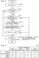
- Fig. 9 is a flowchart illustrating an example of the procedure for the operation performed by the relay ECU 116 to determine the presence/absence of an anomaly of control data, according to the present embodiment.
- Steps S900, S902, S904, S906, and S908 are the same as steps S500, S502, S504, S506, and S908 according to the first embodiment, respectively.
- Step S918 executed when the result of determination in step S902 is NO is the same as step S510 according to the first embodiment.
- step S920 executed immediately after the result of the determination in step S908 is NO is the same as step S512 according to the first embodiment.
- the step corresponding to determination regarding the remote control mode according to the first embodiment may be executed subsequent to step S902.
- step S902 the step corresponding to determination regarding the remote control mode according to the first embodiment
- step S910 If a match is found between the combination of the control command IDs for a control ID described in the control command combination list 600 illustrated in Fig. 6 and the actually extracted combination of the control ID and control command IDs (YES in step S908), the processing performed by the determination unit 402 proceeds to a value check combination list matching process (step S910).
- step S910 the control command ID extracted from the control frame is matched against a value check combination list 1000 illustrated in Fig. 10 .
- a check table used for value check is identified. For example, if three control commands having control command IDs 0x01, 0x03, and 0x04 are included in a control frame, the fields for "0x01 - 0x03", "0x01 - 0x04", and "0x03 - 0x04" of the value check combination list 1000 are referenced to identify the check tables.
- a check table CT2 and the check table CT3 are identified as check tables used for value check. Examples of check tables are illustrated in Figs.
- Each of the check tables CT1 to CT5 indicates anomalous information in the control command, that is, an anomalous combination of data values.
- a first one of the data rows of the check table CT1 illustrated in Fig. 11B indicates that a combination of a steering angle greater than 30 and an acceleration instruction value greater than 100 is anomalous if the control command IDs are 0x01 (steering angle) and 0x02 (accelerator instruction).
- the value of the data to be checked is a numerical value
- the condition may be indicated by, for example, the range of the numerical value.
- the condition may be indicated by a value that is not a numerical value or a value that is not the range of the numerical value.
- the check table CT5 indicates that anomalous control occurs if the details of the acceleration control operation indicates an accelerator instruction value larger than 30 and the details of the turn signal light control operation indicates a "hazard light flashing instruction" (an instruction to flash both right and left turn signal lights simultaneously).
- the above-described value check combination list 1000 and check tables CT1 to CT5 are stored in the nonvolatile memory unit 414 via the setting I/F 418 at the time of manufacturing the vehicle 100.
- the value check combination list 1000 and check tables CT1 to CT5 may be updated by reprogramming via the setting I/F 418 or OTA (Over-The-Air) reprogramming.
- step S912 If there is no check table to be used for value checking (NO in step S912), the received data is sent to the relay unit 406 and is transmitted from the second communication unit 408 to the Ethernet communication line 118 (step S918).
- step S912 determination of an anomalous value combination is made by using the identified check table (step S914).
- the check table CT2 is used for a combination of commands having control command IDs of 0x01 and 0x03.
- the determination unit 402 determines whether either one of the following anomaly conditions is satisfied: "the steering angle indicated by the control command data having a control command ID of 0x01 is greater than 40, and the brake command indicated by the control command data having a control command ID of 0x03 is greater than 200" and "the control command data having a control command ID of 0x01 is less than -40, and the brake command indicated by the control command data having a control command ID of 0x03 is greater than 200".
- step S936 If any one of the anomaly conditions indicated in the identified check table is satisfied (YES in step S916), it is determined that the control data included in the frame is anomalous and, thus, the processing performed by the relay ECU 116 proceeds to the after-anomaly detection process (step S920).
- control data included in the frame is not anomalous.
- the control data determined to be not anomalous is sent to the relay unit 406 and is transmitted from the second communication unit 1108 to the Ethernet communication line 118 (step S918).
- the procedure for determination as to the presence/absence of an anomaly of the control frame made by the relay ECU 116 is performed and completed.
- the determination process is made for each of the frames received by the relay ECU 116.
- the first relay conversion ECU 122 Upon receiving, via the second Ethernet communication line 118, the control frame output by the relay ECU 116 that has determined that the control frame is not anomalous, the first relay conversion ECU 122 sequentially retrieves the control commands from the control frame. According to the present embodiment, the subsequent processes performed on the control frame are the same as those according to the first embodiment.
- the relay ECU 916 determines whether the information in the control command included in a control frame to be relayed satisfies a condition predetermined according to the combination of types of control commands and, thus, detects whether the control frame is anomalous. In this manner, the occurrence of anomalous control of the vehicle 100 caused by execution of anomalous control data can be reliably prevented.
- Fig. 12 is a diagram illustrating an example of the configuration of a vehicle control network system according to a modification of the first or second embodiment.
- the same reference numerals are used for the same constituent elements as those in Fig. 1 , and description of the constituent elements is not repeated.
- an in-vehicle network system 1202 mounted in a vehicle 1200 of the present modification does not include a relay ECU.
- the in-vehicle network system 1202 includes a relay conversion ECU having a plurality of CAN bus interfaces and Ethernet interfaces.
- a plurality of control networks including an Ethernet network and a CAN network are connected to the relay conversion ECU.
- the relay conversion ECU is responsible for determination of an anomaly of the received data, necessary conversion according to the destination of the control data, and transmission of the control data.
- the vehicle 1200 has a self-driving capability and is based on a technology regarding state monitoring and remote control via a communication network, which can be put to practical use in the near future.
- a first CAN communication line 1226 and a second CAN communication line 1228 constituting a CAN network are connected to a relay conversion ECU 1222.
- the first CAN communication line 1226 and the second CAN communication line 1228 correspond to the first CAN communication line 126 and the second CAN communication line 128 according to the first and second embodiments, respectively.
- a variety of control ECUs are connected to each of the Ethernet and CAN systems.
- a first Ethernet communication line 1214, a fourth Ethernet communication line 1238, a fifth Ethernet communication line 1240, and a sixth Ethernet communication line 1242 are connected to the relay conversion ECU 1222.
- the first Ethernet communication line 1214, the fourth Ethernet communication line 1238, the fifth Ethernet communication line 1240, and the sixth Ethernet communication line 1242 correspond to the first Ethernet communication line 114, the fourth Ethernet communication line 138, the fifth Ethernet communication line 140, and the sixth Ethernet communication line 142 according to the first and second embodiments, respectively.
- a variety of ECUs and a TCU are connected to these communication lines.
- the in-vehicle network system 1202 is connected to the vehicle external communication network 108 via radio communication 110 performed by the TCU 112.
- the TCU 112 is connected to each of the control networks via the relay conversion ECU 1222. The configuration of the relay conversion ECU 1222 is described below.
- the in-vehicle network system 1202 is connected to the monitoring server 104 and a remote control device 1206 via the vehicle external communication network 108. According to the present modification, the monitoring server 104 used in the first and second embodiments is not provided.
- the remote control device 1206 Upon receiving a remote control request from the vehicle 1200 via the vehicle external communication network 108, the remote control device 1206 transmits remote control data to the vehicle 1200.
- the remote control device 1206 is implemented by, for example, executing a predetermined program in one or more information processing apparatuses each including a processor, a memory unit, an input/output device, and a communication device.
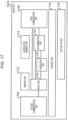
- Fig. 13 is a block diagram illustrating an example of the configuration of the relay conversion ECU 1222.
- the relay ECU 116 includes a first communication unit 1300, a second communication unit 1308, a third communication unit 1310, a fourth communication unit 1312, a fifth communication unit 1314, a sixth communication unit 1315, a memory unit 1316, a nonvolatile memory unit 1318, a determination unit 1302, a generation unit 1304, a relay conversion unit 1306, a control unit 1320, and a setting I/F unit 1322.
- the first communication unit 1300 is connected to the first Ethernet communication line 114 and exchanges data with the TCU 112 via Ethernet.
- the second communication unit 1308 is connected to the fourth Ethernet communication line 1238 and exchanges data with the camera ECU 144 via Ethernet.
- the third communication unit 1310 is connected to the fifth Ethernet communication line 1240 and exchanges data with the sensor ECU 146 via Ethernet.
- the fourth communication unit 1312 is connected to the sixth Ethernet communication line 1242 and exchanges data with the self-driving control ECU 148 via Ethernet.
- the fifth communication unit 1314 is connected to the first CAN communication line 1226 and exchanges data with the turn signal control ECU 1226 via CAN.
- the sixth communication unit 1315 is connected to the second CAN communication line 1228 and exchanges data with the accelerator control ECU 132, the brake control ECU 134, and the steering control ECU 136 via CAN.
- the determination unit 1302, the generation unit 1304, the relay conversion unit 1306, and the control unit 1320 are functional constituent elements achieved by the processor included in the relay ECU 1222 that executes a predetermined program.
- the program is stored in the nonvolatile memory unit 1318 at the time of manufacturing the vehicle 1200 and is executed by using the memory unit 1316.
- Execution of self-driving control and remote control in the vehicle 1200 and switching between the control modes are basically the same as those according to the first and second embodiments.
- the process performed by the relay conversion ECU 1222 which makes the present modification differ from the first and second embodiments, is described below with reference to an example.
- the relay conversion ECU 1222 performs the process by executing the above-described predetermined program.
- the process includes determination as to the presence/absence of an anomaly of control data for the self-driving control operation or remote control operation.
- the flowchart illustrated in Fig. 14 describes an example of the procedure for the operation, which includes determination as to the presence/absence of an anomaly of the control data, performed by the relay conversion ECU 1222 that executes the program.
- differences from the first and second embodiments are mainly described, and description of the processing procedure the same as that of the first embodiment is briefly described as needed.
- step S1400 It is determined by the determination unit 1302 whether the data received by the first communication unit 1300 (step S1400) is a control frame of the vehicle 1200 first (step S1402).
- the frame is sent to the relay conversion unit 1306.
- the frame is transmitted to one or more control networks via one or more of the transmission/reception units 1308 to 1315 corresponding to the destination of the frame (step S1418). Note that if the destination of the frame is a CAN network, the relay conversion unit 1306 performs Ethernet-CAN conversion on the frame and, thereafter, transmits the frame.
- step S1402 If the received data is a control frame (YES in step S1402), the determination unit 1302 extracts the control ID and the control command from the control frame (step S1404).
- steps S1410, S1412, S1414 and S1416 correspond to steps S910, S912, S914 and S916 of the second embodiment, respectively.
- the control command included in the control frame having a destination of a CAN network is subjected to Ethernet-CAN conversion in the relay conversion unit 1306. Thereafter, the control command is transmitted.
- a step corresponding to determination regarding the remote control mode (step S503) made in the first embodiment may be executed subsequently to step S1402.
- a step corresponding to the matching process against the control command combination list (step S506) according to the first embodiment may be executed subsequent to step S1402.
- Determination regarding the remote control mode may be made subsequent to step S1402.
- the matching process against the control command combination list may be performed subsequent to step S1404.
- step S1416 the determination unit 1302 determines that an anomaly is found in the control frame, and the processing performed by the relay conversion ECU 1222 proceeds to the after-anomaly detection process (step S1420).
- the flowchart illustrated in Fig. 15 describes an example of the procedure for the after-anomaly detection process according to the present modification.
- the generation unit 1304 removes, from the received vehicle control frame, a combination of control commands determined to be anomalous in value check (step S1500) and re-generates a control frame (step S1502).
- the control frame without having the removed control command including the anomalous value is sent to the relay conversion unit 1306.
- the control frame is transmitted to one or more of the control networks via one or more of the transmission/reception units 1308 to 1315 corresponding to the destination of the frame (step S1504).
- the relay conversion unit 1306 performs Ethernet-CAN conversion on the frame and transmits the frame. This conversion includes conversion of the control command ID into the CAN ID using the control command ID conversion table 800.
- the generation unit 1304 generates an anomaly message packet for notifying that an anomaly has been detected (step S1506).
- the anomaly message packet is transmitted to the relay conversion unit 1306 and the first communication unit 1300 and is transmitted from the second to sixth communication units 1308 to 1315 to the control network of the vehicle 1200.
- the anomaly message packet is transmitted from the first communication unit 1300 to the remote control device 1306 outside the vehicle (step S1508).
- the first and second embodiments and the modifications thereof have been described as examples of a technique according to the present disclosure.
- the technique according to the present disclosure is not limited thereto.
- the technique is applicable to the embodiments for which a change, substitution, addition, and deletion are made as appropriate.
- the following modifications are also encompassed within an aspect of the present disclosure.
- the configuration of the in-vehicle control network is not limited to those illustrated in Fig. 1 or Fig. 12 .
- the technique according to the present disclosure is applicable to an intermediate configuration of the configuration illustrated in Fig. 1 or 12 .
- Fig. 16 is a diagram illustrating an example of such a configuration of a vehicle control network system.
- a vehicle 1600 according to the modification includes a vehicle control network system 1602.
- the vehicle control network system 1602 has a relay ECU that relays data between the relay conversion ECU and the TCU, like the in-vehicle network system 102.
- the relay conversion ECUs differ from each other.
- the vehicle control network system 1602 includes a relay ECU.
- the vehicle control network system 1602 has only one relay conversion ECU to which all of the control networks (the CAN networks and the Ethernet networks) are connected.
- a determination of an anomaly of the control data may be made by either a relay ECU 1616 or a relay conversion ECU 1622. If the determination is made by the relay ECU 1616, the relay ECU 1616 has a configuration indicated by the block diagram illustrated of Fig. 17 .
- the configuration is also an example of the configuration of the in-vehicle control network system.
- the configuration may include, for example, an ECU that further provides functions other than those described above.
- the configuration may include an increased number of CAN networks or Ethernet networks.
- different system control ECUs may be connected to one CAN network.
- the plurality of functions are provided by the plurality of ECUs.
- the plurality of functions may be provided by a single ECU.
- the relay ECU 1 or the relay conversion ECU may acquire the state of the vehicle on the basis of, for example, state data indicating the state of the vehicle and transmitted from each of the control ECUs.
- the relay ECU 1 or the relay conversion ECU may acquire the state of the vehicle from the monitoring server outside the vehicle.
- Examples of the state of the vehicle include, but not limited to, the type of controller (e.g., manual driving, self-driving, or remote control), an ON/OFF operation of a particular temporary function (e.g., an autoparking function), information as to whether a breakdown of a particular part occurs, a driving location, weather, a travel speed, a shift position, a fuel level or a battery level, and information as to whether an obstacle is detected.
- the type of controller e.g., manual driving, self-driving, or remote control
- an ON/OFF operation of a particular temporary function e.g., an autoparking function
- information as to whether a breakdown of a particular part occurs e.g., a driving location, weather, a travel speed, a shift position, a fuel level or a battery level, and information as to whether an obstacle is detected.
- the vehicle 100 and the remote control device 106 communicating with each other via the TCU may be used.
- another path such as Wi-Fi
- the functions of the TCU may be included in another ECU not mentioned above, such as an ECU that provides the IVI (In-Vehicle Infotainment) function.
- a TLS session may be established between the remote control device 106 and one of the relay ECU 116 and the relay conversion ECU 1222.
- a control frame format to be processed is not limited to the control frame format 200 illustrated in Fig. 2 .
- a control frame format 1800A illustrated in Fig. 18A may be employed in a vehicle for which remote control is not performed.
- a determination of an anomaly can be made for even the control frame format 1800B not having a control ID indicating the type of control as illustrated in Fig. 18B .
- a combination of types of control commands each indicated by the control command ID of a control command is not a preset certain combination, it may be determined that an anomaly occurs regardless of the type of control indicated by the control ID.
- a broader range and more exhaustive combination of control frames can be subjected to a determination of anomaly, and anomaly detection can be performed for various details of control operations indicated by combinations of control frames. It should be noted that even when anomaly detection is performed on a control frame having a format including a control ID, anomaly detection may be performed on the basis of a combination of control commands each indicated by a control command ID without using the control ID.
- a control frame format 1500 illustrated in Fig. 18C may be employed.
- a CAN ID and a CAN payload (a data field) are used as a control command ID and control command data, respectively.
- control frames having different formats can be used.
- various data are written into the nonvolatile memory unit via the setting I/F unit.
- the various data may be written via any one of the communication units, instead of the setting I/F unit.
- the range of application of the technology according to the present disclosure is not limited thereto.
- the technology according to the present disclosure is applicable to a network systems that comply with various standards, such as CAN-FD, Ethernet (registered trademark), MOST, LIN (Local Interconnect Network), and Flexray (registered trademark).
- CAN-FD Ethernet
- MOST MOST
- LIN Local Interconnect Network
- Flexray registered trademark
- the determination of an anomaly of the control data may be made by a monitoring device that is located on an Ethernet network and that is not involved in the relay function, for example.
- the application range of the present disclosure is not limited thereto.
- the present disclosure is applicable to the field of mobility, such as a construction machine, an agricultural machine, a ship, a railway, or an airplane.
- the present disclosure is effectively applicable to the industrial field and the field of factory control, such as a smart factory.
- the in-vehicle relay device or the like has a function of detecting an anomaly of control data used for driving assistance or self-driving control of an automobile.
- the in-vehicle relay device is useful for in-vehicle control network systems of an automobile and a self-driving vehicle.
- the in-vehicle relay device is also applicable to remote control of manufacturing systems in factories.
Landscapes
- Engineering & Computer Science (AREA)
- Computer Networks & Wireless Communication (AREA)
- Signal Processing (AREA)
- General Health & Medical Sciences (AREA)
- Medical Informatics (AREA)
- Health & Medical Sciences (AREA)
- Computing Systems (AREA)
- Computer Hardware Design (AREA)
- General Engineering & Computer Science (AREA)
- Physics & Mathematics (AREA)
- General Physics & Mathematics (AREA)
- Small-Scale Networks (AREA)
- Computer Security & Cryptography (AREA)
Claims (18)
- Fahrzeuginterne Übertragungsvorrichtung zum Übertragen von Kommunikation zwischen einer Vielzahl von Steuerungsvorrichtungen in einem Fahrzeug (100, 1200, 1600) über eine Vielzahl von Netzwerken, mit denen die Vielzahl von Steuerungsvorrichtungen verbunden ist, wobei die Vielzahl von Netzwerken ein erstes und ein zweites Steuerungs-Netzwerk einschließt, in dem ersten Steuerungs-Netzwerk die größte Datengröße eines Steuerungs-Befehls, der in einem Rahmen gesendet werden kann, größer ist als die größte Datengröße eines Steuerungs-Befehls, der in einem Rahmen gesendet werden kann, in dem zweiten Steuerungs-Netzwerk, und wobei die fahrzeuginterne Übertragungsvorrichtung umfasst:eine Kommunikations-Einheit (400, 408, 410, 1300, 1308, 1310, 1312, 1314, 1315, 1700, 1708), die Steuerungs-Daten von dem ersten Steuerungs-Netzwerk empfängt, das in der Vielzahl von Netzwerken enthalten ist, wobei die Steuerungs-Daten in einem Rahmen eine Vielzahl durch wenigstens einige der Steuerungsvorrichtungen auszuführender Steuerungs-Befehle enthalten; sowieeine Feststellungs-Einheit (402, 1302, 1702), die eine erste Feststellung dahingehend trifft, ob Typen der in dem Rahmen enthaltenen Steuerungs-Befehle eine erste Kombination bilden, die als eine Kombination gleichzeitig ausführbarer Steuerungs-Befehle voreingestellt ist, und danach unter Verwendung eines Ergebnisses der ersten Feststellung eine zweite Feststellung dahingehend trifft, ob die Steuerungs-Daten anomal sind, und ein Ergebnis der zweiten Feststellung ausgibt.
- Fahrzeuginterne Übertragungsvorrichtung nach Anspruch 1, wobei die Feststellungs-Einheit (402, 1302, 1702), wenn die erste Feststellung ergibt, dass die Kombination der Typen von Steuerungs-Befehlen nicht die erste Kombination ist, bei der zweiten Feststellung feststellt, dass die Steuerungs-Daten anomal sind.
- Fahrzeuginterne Übertragungsvorrichtung nach Anspruch 2, wobei die Steuerungs-Daten des Weiteren eine Steuerungs-Kennung einschließen, die einen Typ von Steuerung angibt, und
die erste Kombination für den durch die Steuerungs-Kennung angegebenen Typ von Steuerung eingestellt ist. - Fahrzeuginterne Übertragungsvorrichtung nach Anspruch 2 oder 3, wobei die Feststellungs-Einheit (402, 1302, 1702) Status-Daten erfasst, die einen Status des Fahrzeugs (100, 1200, 1600) anzeigen, und die erste Feststellung unter Verwendung der ersten Kombination trifft, die sich entsprechend dem durch die Status-Daten angezeigten Status ändert.
- Fahrzeuginterne Übertragungsvorrichtung nach Anspruch 4, wobei die Status-Daten auf Daten basieren, die durch wenigstens einige der Steuerungsvorrichtungen gesendet werden.
- Fahrzeuginterne Übertragungsvorrichtung nach einem der Ansprüche 1 bis 5, wobei die Feststellungs-Einheit (402, 1302, 1702), wenn die erste Feststellung ergibt, dass die Kombination der Typen von Steuerungs-Befehlen die erste Kombination ist, des Weiteren eine dritte Feststellung dahingehend trifft, ob eine Kombination von Informationen in den Steuerungs-Befehlen eine für die erste Kombination voreingestellte zweite Kombination ist, und ein Ergebnis der dritten Feststellung ausgibt, und
wobei, wenn bei der dritten Feststellung die Kombination von Informationen in den Steuerungs-Befehlen nicht die zweite Kombination ist, die Feststellungs-Einheit (402, 1302, 1702) feststellt, dass die Steuerungs-Daten anomal sind. - Fahrzeuginterne Übertragungsvorrichtung nach Anspruch 6, wobei die zweite Kombination eine Kombination vorgegebener Wertebereiche ist, in denen jeweils ein in einem der Steuerungs-Befehle enthaltener Betriebswert enthalten sein soll.
- Fahrzeuginterne Übertragungsvorrichtung nach Anspruch 7, wobei die Feststellungs-Einheit (402, 1302, 1702) die Status-Daten erfasst, die den Status des Fahrzeugs (100, 1200, 1600) anzeigen, und die vorgegebenen Bereiche verwendet, die sich entsprechend dem durch die Status-Daten angezeigten Status ändern.
- Fahrzeuginterne Übertragungsvorrichtung nach einem der Ansprüche 1 bis 8, die des Weiteren umfasst:eine Übertragungs-Einheit (406, 1306, 1706),wobei, wenn das von der Feststellungs-Einheit (402, 1302, 1702) ausgegebene Ergebnis anzeigt, dass die Steuerungs-Daten nicht anomal sind, die Übertragungs-Einheit (406, 1306, 1706) die Vielzahl von Steuerungs-Befehlen zu dem zweiten Steuerungs-Netzwerk der Vielzahl von Steuerungs-Netzwerken sendet, undwobei sich das zweite Steuerungs-Netzwerk von dem ersten Steuerungs-Netzwerk unterscheidet und ein vorgegebenes Ziel ist, das jedem der Steuerungs-Befehle entspricht.
- Fahrzeuginterne Übertragungsvorrichtung nach Anspruch 9, wobei die Steuerungs-Daten des Weiteren Kennungen von Steuerungs-Befehlen einschließen, die jeweils den Typ eines der Steuerungs-Befehle angeben, und
wobei die Übertragungs-Einheit (406, 1306, 1706) jede der Kennungen von Steuerungs-Befehlen, die den Typ des Steuerungs-Befehls angeben, gemäß einer vorgegebenen Umwandlungsregel in eine Kennung eines Steuerungs-Befehls umwandelt und die Kennung des Steuerungs-Befehls zusammen mit dem Steuerungs-Befehl zu dem zweiten Steuerungs-Netzwerk sendet. - Fahrzeuginterne Übertragungsvorrichtung nach Anspruch 10, wobei die Übertragungs-Einheit (406, 1306, 1706) jeden der Steuerungs-Befehle gemäß einer vorgegebenen Umwandlungsregel umwandelt und den Steuerungs-Befehl sendet.
- Fahrzeuginterne Übertragungsvorrichtung nach Anspruch 11, wobei in dem ersten Steuerungs-Netzwerk die größte Datengröße des Steuerungs-Befehls, der in dem einen Rahmen übertragen werden kann, größer ist als die größte Datengröße des Steuerungs-Befehls, der in einem Rahmen übertragen werden kann, in dem zweiten Steuerungs-Netzwerk, und
wobei die Übertragungs-Einheit (406, 1306, 1706) eine Vielzahl von Steuerungs-Befehlen, die in einem Rahmen der von dem ersten Steuerungs-Netzwerk empfangenen Steuerungs-Daten enthalten sind, in eine Vielzahl von Rahmen trennt und die Rahmen zu dem zweiten Steuerungs-Netzwerk sendet. - Fahrzeuginterne Übertragungsvorrichtung nach Anspruch 12, wobei das erste Steuerungs-Netzwerk und das zweite Steuerungs-Netzwerk unterschiedlichen Standards entsprechen, und/oder
wobei der Standard, dem das erste Steuerungs-Netzwerk entspricht, Ethernet (eingetragenes Warenzeichen) ist, und der Standard, dem das zweite Steuerungs-Netzwerk entspricht, CAN (Controller Area Network) ist. - Fahrzeuginterne Übertragungsvorrichtung nach Anspruch 1, wobei
eine extrahierte Steuerungs-Kennung und eine Kennung eines Steuerungs-Befehls mit einer Liste (600) von Kombinationen von Steuerungs-Befehlen abgeglichen wird, bei der es sich um eine Liste handelt, die eine Kombination durch die Steuerungs-Kennung angegebener geeigneter Typen von Steuerungs-Befehlen beschreibt, die für eine Steuerungs-Kennung eingestellt ist. - Fahrzeuginterne Überwachungsvorrichtung, die in einem fahrzeuginternen Netzwerk enthalten ist, das ein erstes Steuerungs-Netzwerk und ein zweites Steuerungs-Netzwerk aufweist, zwischen denen Kommunikation durch eine Übertragungsvorrichtung übertragen wird, und die mit dem ersten Steuerungs-Netzwerk verbunden ist, wobei die fahrzeuginterne Überwachungsvorrichtung umfasst:eine Kommunikations-Einheit (400, 408, 410, 1300, 1308, 1310, 1312, 1314, 1315, 1700, 1708), die Steuerungs-Daten empfängt, die von einer mit dem ersten Steuerungs-Netzwerk verbundenen Steuerungsvorrichtung gesendet werden, wobei die Steuerungs-Daten in einem Rahmen eine Vielzahl von Steuerungs-Befehlen für durch eine mit dem zweiten Steuerungs-Netzwerk verbundene Steuerungsvorrichtung durchzuführende Steuerung einschließen; sowieeine Feststellungs-Einheit (402, 1302, 1702), die eine erste Feststellung dahingehend trifft, ob Typen der in dem Rahmen enthaltenen Steuerungs-Befehle, eine erste Kombination bilden, die als eine Kombination gleichzeitig ausführbarer Steuerungs-Befehle voreingestellt ist, unter Verwendung eines Ergebnisses der ersten Feststellung eine zweite Feststellung dahingehend trifft, ob die Steuerungs-Daten anomal sind, und ein Ergebnis der zweiten Feststellung ausgibt,wobei in dem ersten Steuerungs-Netzwerk die größte Datengröße des Steuerungs-Befehls, der in einem Rahmen gesendet werden kann, größer ist als die größte Datengröße des Steuerungs-Befehls, der in einem Rahmen gesendet werden kann, in dem zweiten Steuerungs-Netzwerk.
- Kommunikations-Überwachungsverfahren zum Einsatz in einer fahrzeuginternen Übertragungsvorrichtung, die Kommunikation zwischen einer Vielzahl von Steuerungsvorrichtungen in einem Fahrzeug (100, 1200, 1600) über eine Vielzahl von Netzwerken überträgt, mit denen die Vielzahl von Steuerungsvorrichtungen verbunden ist, wobei die Vielzahl von Netzwerken ein erstes und ein zweites Steuerungs-Netzwerk einschließt, in dem ersten Steuerungs-Netzwerk die größte Datengröße eines Steuerungs-Befehls, der in einem Rahmen gesendet werden kann, größer ist als die größte Datengröße eines Steuerungs-Befehls, der in einem Rahmen gesendet werden kann, in dem zweiten Steuerungs-Netzwerk, wobei die fahrzeuginterne Übertragungsvorrichtung eine Kommunikations-Einheit (400, 408, 410, 1300, 1308, 1310, 1312, 1314, 1315, 1700, 1708) sowie einen Prozessor enthält und das Verfahren die folgenden Schritte umfasst:Empfangen von Steuerungs-Daten von einem ersten Steuerungs-Netzwerk, das in der Vielzahl von Netzwerken enthalten ist, unter Einsatz der Kommunikations-Einheit (400, 408, 410, 1300, 1308, 1310, 1312, 1314, 1315, 1700, 1708), wobei die Steuerungs-Daten in einem Rahmen eine Vielzahl durch wenigstens einige der Steuerungsvorrichtungen auszuführender Steuerungs-Befehle enthalten; sowieTreffen einer ersten Feststellung dahingehend, ob Typen der in dem Rahmen enthaltenen Steuerungs-Befehle eine erste Kombination bilden, die als eine Kombination gleichzeitig ausführbarer Steuerungs-Befehle voreingestellt ist, und danach Treffen einer zweiten Feststellung dahingehend, ob die Steuerungs-Daten anomal sind, unter Verwendung eines Ergebnisses der ersten Feststellung sowie Ausgeben eines Ergebnisses der zweiten Feststellung unter Einsatz des Prozessors.
- Programm zum Einsatz in einer fahrzeuginternen Übertragungsvorrichtung, die Kommunikation zwischen einer Vielzahl von Steuerungsvorrichtungen in einem Fahrzeug (100, 1200, 1600) über eine Vielzahl von Netzwerken überträgt, mit denen die Vielzahl von Steuerungsvorrichtungen verbunden ist, wobei die fahrzeuginterne Übertragungsvorrichtung eine Kommunikations-Einheit (400, 408, 410, 1300, 1308, 1310, 1312, 1314, 1315, 1700, 1708) sowie einen Prozessor enthält, die Vielzahl von Netzwerken ein erstes und ein zweites Steuerungs-Netzwerk einschließt, in dem ersten Steuerungs-Netzwerk die größte Datengröße eines Steuerungs-Befehls, der in einem Rahmen gesendet werden kann, größer ist als die größte Datengröße eines Steuerungs-Befehls, der in einem Rahmen gesendet werden kann, in dem zweiten Steuerungs-Netzwerk, und wobei das Programm einen Programmcode umfasst, der, wenn er von dem Prozessor ausgeführt wird, den Prozessor veranlasst, die folgenden Schritte durchzuführen:Empfangen von Steuerungs-Daten von einem ersten Steuerungs-Netzwerk, das in der Vielzahl von Netzwerken enthalten ist, unter Einsatz der Kommunikations-Einheit (400, 408, 410, 1300, 1308, 1310, 1312, 1315, 1700, 1708), wobei die Steuerungs-Daten in einem Rahmen eine Vielzahl durch wenigstens einige der Steuerungsvorrichtungen auszuführender Steuerungs-Befehle enthalten; sowieTreffen einer ersten Feststellung dahingehend, ob Typen der in dem Rahmen enthaltenen Steuerungs-Befehle eine erste Kombination bilden, die als eine Kombination gleichzeitig ausführbarer Steuerungs-Befehle voreingestellt ist, und danach Treffen einer zweiten Feststellung dahingehend, ob die Steuerungs-Daten anomal sind, unter Verwendung eines Ergebnisses der ersten Feststellung sowie Ausgeben eines Ergebnisses der zweiten Feststellung unter Einsatz des Prozessors.
- Fahrzeuginternes Steuerungs-Netzwerksystem, das umfasst:eine Vielzahl von Steuerungsvorrichtungen in einem Fahrzeug (100, 1200, 1600);eine Vielzahl von Netzwerken, mit denen die Vielzahl von Steuerungsvorrichtungen verbunden sind;eine fahrzeuginterne Übertragungsvorrichtung zum Übertragen von Kommunikation zwischen der Vielzahl von Steuerungsvorrichtungen in einem Fahrzeug (100, 1200, 1600) über die Vielzahl von Netzwerken, mit denen die Vielzahl von Steuerungsvorrichtungen verbunden sind;ein erstes und ein zweites Steuerungs-Netzwerk, die in der Vielzahl von Netzwerken eingeschlossen sind, wobei in dem ersten Steuerungs-Netzwerk die größte Datengröße eines Steuerungs-Befehls, der in einem Rahmen gesendet werden kann, größer ist als die größte Datengröße eines Steuerungs-Befehls, der in einem Rahmen gesendet werden kann, in dem zweiten Steuerungs-Netzwerk,wobei die fahrzeuginteme Übertragungsvorrichtung umfasst:eine Kommunikations-Einheit (400, 408, 410, 1300, 1308, 1310, 1312, 1314, 1315, 1700, 1708), die Steuerungs-Daten von dem ersten Steuerungs-Netzwerk empfängt, das in der Vielzahl von Netzwerken enthalten ist, wobei die Steuerungs-Daten in einem Rahmen eine Vielzahl durch wenigstens einige der Steuerungsvorrichtungen auszuführender Steuerungs-Befehle enthalten; sowieeine Feststellungs-Einheit (402, 1302, 1702), die eine erste Feststellung dahingehend trifft, ob Typen der in dem Rahmen enthaltenen Steuerungs-Befehle eine erste Kombination bilden, die als eine Kombination gleichzeitig ausführbarer Steuerungs-Befehle voreingestellt ist, und danach unter Verwendung eines Ergebnisses der ersten Feststellung eine zweite Feststellung dahingehend trifft, ob die Steuerungs-Daten anomal sind, und ein Ergebnis der zweiten Feststellung ausgibt.
Applications Claiming Priority (2)
| Application Number | Priority Date | Filing Date | Title |
|---|---|---|---|
| PCT/JP2017/027120 WO2019021403A1 (ja) | 2017-07-26 | 2017-07-26 | 制御ネットワークシステム、車両遠隔制御システム及び車載中継装置 |
| PCT/JP2018/027011 WO2019021921A1 (ja) | 2017-07-26 | 2018-07-19 | 車載中継装置、車載監視装置、車載制御ネットワークシステム、通信監視方法及びプログラム |
Publications (3)
| Publication Number | Publication Date |
|---|---|
| EP3661132A1 EP3661132A1 (de) | 2020-06-03 |
| EP3661132A4 EP3661132A4 (de) | 2020-08-05 |
| EP3661132B1 true EP3661132B1 (de) | 2024-09-04 |
Family
ID=65040083
Family Applications (1)
| Application Number | Title | Priority Date | Filing Date |
|---|---|---|---|
| EP18838223.8A Active EP3661132B1 (de) | 2017-07-26 | 2018-07-19 | Fahrzeugmontierte relaisvorrichtung, fahrzeugmontierte überwachungsvorrichtung, fahrzeugmontiertes steuernetzwerksystem, kommunikationsüberwachungsverfahren und programm |
Country Status (5)
| Country | Link |
|---|---|
| US (1) | US11381420B2 (de) |
| EP (1) | EP3661132B1 (de) |
| JP (1) | JP7133977B2 (de) |
| CN (1) | CN109906587B (de) |
| WO (2) | WO2019021403A1 (de) |
Families Citing this family (39)
| Publication number | Priority date | Publication date | Assignee | Title |
|---|---|---|---|---|
| CN108196967B (zh) * | 2017-12-12 | 2023-04-18 | 深圳市道通科技股份有限公司 | 基于车辆总线的通讯方法、装置和计算机设备 |
| CN111466107A (zh) * | 2017-12-15 | 2020-07-28 | 通用汽车环球科技运作有限责任公司 | 用于载具内控制器的以太网网络剖析入侵检测控制逻辑和架构 |
| CN110771099B (zh) | 2018-05-23 | 2022-08-26 | 松下电器(美国)知识产权公司 | 异常检测装置、异常检测方法以及记录介质 |
| JP6962301B2 (ja) * | 2018-09-25 | 2021-11-05 | 株式会社オートネットワーク技術研究所 | 中継装置 |
| JP2020050048A (ja) * | 2018-09-25 | 2020-04-02 | 株式会社オートネットワーク技術研究所 | 中継装置システム |
| CN111835627B (zh) * | 2019-04-23 | 2022-04-26 | 华为技术有限公司 | 车载网关的通信方法、车载网关及智能车辆 |
| KR102812679B1 (ko) * | 2019-06-17 | 2025-05-26 | 현대자동차주식회사 | 제어기 통신 장치 및 그 방법 |
| JP7283988B2 (ja) * | 2019-06-18 | 2023-05-30 | 日立Astemo株式会社 | 車両用制御装置 |
| JP7120171B2 (ja) * | 2019-07-09 | 2022-08-17 | トヨタ自動車株式会社 | 車載ネットワークシステム |
| JP7408939B2 (ja) * | 2019-07-18 | 2024-01-09 | マツダ株式会社 | ネットワークハブ装置 |
| JP7342476B2 (ja) * | 2019-07-18 | 2023-09-12 | マツダ株式会社 | 車載ネットワークシステム |
| CN117896698A (zh) * | 2019-08-01 | 2024-04-16 | 住友电气工业株式会社 | 中继装置、车辆通信系统、通信方法及记录介质 |
| CN112468528B (zh) * | 2019-09-06 | 2022-03-18 | 比亚迪股份有限公司 | 车辆的双路WiFi实现方法以及车载信息娱乐系统 |
| CN115716455A (zh) * | 2019-09-12 | 2023-02-28 | 华为技术有限公司 | 实现汽车中电子控制功能的系统、方法以及汽车 |
| US11411823B2 (en) | 2019-09-20 | 2022-08-09 | Sonatus, Inc. | System, method, and apparatus to support mixed network communications on a vehicle |
| US11538287B2 (en) | 2019-09-20 | 2022-12-27 | Sonatus, Inc. | System, method, and apparatus for managing vehicle data collection |
| US12261747B2 (en) | 2019-09-20 | 2025-03-25 | Sonatus, Inc. | System, method, and apparatus to execute vehicle communications using a zonal architecture |
| WO2021070914A1 (ja) * | 2019-10-09 | 2021-04-15 | パナソニック インテレクチュアル プロパティ コーポレーション オブ アメリカ | 機器監視方法、機器監視装置、及びプログラム |
| JP7447912B2 (ja) * | 2019-10-28 | 2024-03-12 | 住友電気工業株式会社 | 中継装置、車載通信システム、車載通信プログラムおよび車載通信方法 |
| CN114503616B (zh) | 2019-10-28 | 2025-06-13 | 住友电气工业株式会社 | 中继装置、车载通信系统、车辆及车载通信方法 |
| CN114467263B (zh) * | 2019-10-28 | 2023-08-29 | 住友电气工业株式会社 | 中继装置、车载通信系统、车辆及车载通信方法 |
| JP7192747B2 (ja) * | 2019-11-13 | 2022-12-20 | 株式会社オートネットワーク技術研究所 | 車載中継装置及び情報処理方法 |
| JP7251489B2 (ja) * | 2020-01-21 | 2023-04-04 | 株式会社オートネットワーク技術研究所 | 車載無線通信装置、無線通信システム、無線通信装置及び車両制御方法 |
| US12211323B2 (en) | 2020-03-06 | 2025-01-28 | Sonatus, Inc. | System, method, and apparatus for managing vehicle automation |
| US12528442B2 (en) | 2020-03-06 | 2026-01-20 | Sonatus, Inc. | System, method, and apparatus for managing vehicle data collection |
| US12403921B2 (en) | 2020-03-06 | 2025-09-02 | Sonatus, Inc. | System, method, and apparatus for managing vehicle automation |
| US11772583B2 (en) | 2020-03-06 | 2023-10-03 | Sonatus, Inc. | System, method, and apparatus for managing vehicle automation |
| US12094259B2 (en) | 2020-03-06 | 2024-09-17 | Sonatus, Inc. | System, method, and apparatus for managing vehicle automation |
| US12573245B2 (en) | 2020-03-06 | 2026-03-10 | Sonatus, Inc. | System, method, and apparatus for managing vehicle automation |
| US12103479B2 (en) | 2020-03-06 | 2024-10-01 | Sonatus, Inc. | System, method, and apparatus for managing vehicle automation |
| JP7322843B2 (ja) * | 2020-09-23 | 2023-08-08 | 株式会社デンソー | 車載中継装置 |
| JP7151930B2 (ja) * | 2020-10-19 | 2022-10-12 | 日産自動車株式会社 | 中継装置、通信ネットワークシステム及び通信制御方法 |
| JP2022091585A (ja) * | 2020-12-09 | 2022-06-21 | トヨタ自動車株式会社 | 車両通信用中継装置、車両通信用中継方法及びプログラム |
| JP7631960B2 (ja) * | 2021-03-24 | 2025-02-19 | 村田機械株式会社 | 無線通信システム、コントローラ、無線基地局、及びデータパケット転送方法 |
| JP7613246B2 (ja) * | 2021-04-28 | 2025-01-15 | 株式会社オートネットワーク技術研究所 | 車載中継装置、中継方法および中継プログラム |
| CN113176987B (zh) * | 2021-04-29 | 2023-09-15 | 华人运通(上海)云计算科技有限公司 | 车控指令块的日志处理方法、装置、设备及存储介质 |
| DE102022112112A1 (de) * | 2021-05-21 | 2022-11-24 | Melexis Technologies NVMelexis Technologies NV | Busgesteuertes beleuchtungssystem |
| JP7765294B2 (ja) * | 2022-01-20 | 2025-11-06 | Astemo株式会社 | 電子制御装置及び通信システム |
| CN120111118A (zh) * | 2023-11-30 | 2025-06-06 | 富泰京精密电子(烟台)有限公司 | 基于车载以太网的数据传输方法及相关设备 |
Family Cites Families (22)
| Publication number | Priority date | Publication date | Assignee | Title |
|---|---|---|---|---|
| JP3767481B2 (ja) * | 2001-12-27 | 2006-04-19 | 株式会社デンソー | インターフェイス装置 |
| JP2010166160A (ja) * | 2009-01-13 | 2010-07-29 | Toyota Motor Corp | 車載ゲートウェイ装置、車両制御システム、及び車両制御方法 |
| WO2010116416A1 (ja) * | 2009-04-08 | 2010-10-14 | トヨタ自動車株式会社 | データ中継装置、及び当該装置で用いられるデータ中継方法 |
| JP2012026842A (ja) * | 2010-07-22 | 2012-02-09 | Sony Corp | 情報処理装置、情報処理方法、及びプログラム |
| CN102572744B (zh) * | 2010-12-13 | 2014-11-05 | 中国移动通信集团设计院有限公司 | 识别特征库获取方法、装置及短消息识别方法、装置 |
| JP2014058210A (ja) * | 2012-09-18 | 2014-04-03 | Hitachi Automotive Systems Ltd | 車両制御装置および車両制御システム |
| JP6094439B2 (ja) * | 2013-09-30 | 2017-03-15 | 株式会社デンソー | 車両制御システム |
| KR101536141B1 (ko) * | 2014-02-13 | 2015-07-13 | 현대자동차주식회사 | 이더넷과 can 통신 간의 신호 변환을 제공하는 차량용 장치 및 그 제어방법 |
| EP3133774B1 (de) * | 2014-04-17 | 2020-11-25 | Panasonic Intellectual Property Corporation of America | Fahrzeugmontiertes netzwerksystem, elektronische steuereinheit für anomalieerkennung und anomalieerkennungsverfahren |
| EP3142289B1 (de) | 2014-05-08 | 2020-10-07 | Panasonic Intellectual Property Corporation of America | Fahrzeuginternes netzwerksystem, elektronische steuereinheit und detektionsverfahren für unregelmässigkeiten |
| CN105981336B (zh) * | 2014-12-01 | 2020-09-01 | 松下电器(美国)知识产权公司 | 不正常检测电子控制单元、车载网络系统以及不正常检测方法 |
| JP2016111477A (ja) * | 2014-12-04 | 2016-06-20 | トヨタ自動車株式会社 | 通信システム、及びゲートウェイ |
| JP6594732B2 (ja) * | 2015-01-20 | 2019-10-23 | パナソニック インテレクチュアル プロパティ コーポレーション オブ アメリカ | 不正フレーム対処方法、不正検知電子制御ユニット及び車載ネットワークシステム |
| JP6477281B2 (ja) * | 2015-06-17 | 2019-03-06 | 株式会社オートネットワーク技術研究所 | 車載中継装置、車載通信システム及び中継プログラム |
| US10708293B2 (en) * | 2015-06-29 | 2020-07-07 | Argus Cyber Security Ltd. | System and method for time based anomaly detection in an in-vehicle communication network |
| US20180324640A1 (en) | 2015-11-25 | 2018-11-08 | Hitachi Automotive Systems, Ltd. | Vehicle-Mounted Gateway Device, Electronic Control Device, and Vehicle-Mounted Network System |
| CN105320050A (zh) * | 2015-11-27 | 2016-02-10 | 奇瑞汽车股份有限公司 | 一种基于网关的车辆功能集中控制方法 |
| JP2017174111A (ja) * | 2016-03-23 | 2017-09-28 | 株式会社東芝 | 車載ゲートウェイ装置、蓄積制御方法およびプログラム |
| JP6962697B2 (ja) * | 2016-05-27 | 2021-11-05 | パナソニック インテレクチュアル プロパティ コーポレーション オブ アメリカPanasonic Intellectual Property Corporation of America | ネットワークハブ、転送方法及び車載ネットワークシステム |
| EP3523943B1 (de) * | 2016-10-07 | 2024-09-18 | Vitanet Japan, Inc. | Datenverarbeitung mit definierten datendefinitionen |
| JP7124303B2 (ja) * | 2017-12-04 | 2022-08-24 | トヨタ自動車株式会社 | 車載中継装置、情報処理装置、中継装置、情報処理方法、プログラム、情報処理システム、及び車両 |
| JP7131372B2 (ja) * | 2018-12-25 | 2022-09-06 | 住友電装株式会社 | 車載通信装置 |
-
2017
- 2017-07-26 WO PCT/JP2017/027120 patent/WO2019021403A1/ja not_active Ceased
-
2018
- 2018-05-22 JP JP2018098026A patent/JP7133977B2/ja active Active
- 2018-07-19 EP EP18838223.8A patent/EP3661132B1/de active Active
- 2018-07-19 WO PCT/JP2018/027011 patent/WO2019021921A1/ja not_active Ceased
- 2018-07-19 CN CN201880004048.6A patent/CN109906587B/zh active Active
-
2020
- 2020-01-06 US US16/734,435 patent/US11381420B2/en active Active
Also Published As
| Publication number | Publication date |
|---|---|
| EP3661132A4 (de) | 2020-08-05 |
| US11381420B2 (en) | 2022-07-05 |
| WO2019021921A1 (ja) | 2019-01-31 |
| JP2019029994A (ja) | 2019-02-21 |
| CN109906587A (zh) | 2019-06-18 |
| US20200145252A1 (en) | 2020-05-07 |
| EP3661132A1 (de) | 2020-06-03 |
| CN109906587B (zh) | 2022-05-13 |
| JP7133977B2 (ja) | 2022-09-09 |
| WO2019021403A1 (ja) | 2019-01-31 |
Similar Documents
| Publication | Publication Date | Title |
|---|---|---|
| EP3661132B1 (de) | Fahrzeugmontierte relaisvorrichtung, fahrzeugmontierte überwachungsvorrichtung, fahrzeugmontiertes steuernetzwerksystem, kommunikationsüberwachungsverfahren und programm | |
| US11539727B2 (en) | Abnormality detection apparatus and abnormality detection method | |
| US11438355B2 (en) | In-vehicle network anomaly detection system and in-vehicle network anomaly detection method | |
| EP3923550A1 (de) | Internes fahrzeugkommunikationssystem und verfahren sowie vorrichtung | |
| US20200334926A1 (en) | Anomaly detection electronic control unit, in-vehicle network system, and anomaly detection method | |
| EP2178257B1 (de) | Routing-Verfahren in einer fahrzeuginternen Gateway-Vorrichtung | |
| US20190367041A1 (en) | Electronic control device, recording medium, and gateway device | |
| CN103843046B (zh) | 用于分配式传递通信流的方法和系统以及系统的应用 | |
| US12592874B2 (en) | Validation of time synchronization | |
| US9721469B2 (en) | Filtering infrastructure description messages | |
| CN107078938A (zh) | 网关装置、车载网络系统以及通信方法 | |
| US20200139995A1 (en) | Secure locomotive communication system | |
| EP3854651A1 (de) | Elektronische steuervorrichtung, elektronisches steuerungsverfahren und programm | |
| JP4124948B2 (ja) | 移動体電子装置 | |
| CN104040929A (zh) | 用于识别被冗余地接收的信息的方法、车对x通信系统以及该系统的应用 | |
| WO2017047469A1 (ja) | 通信制御装置及び通信システム | |
| JP6519830B1 (ja) | 電子制御装置、監視方法、プログラム及びゲートウェイ装置 | |
| JP2019209962A (ja) | 情報処理装置、監視方法、プログラム及びゲートウェイ装置 | |
| TWI613625B (zh) | 交通管理系統及其交通管理方法 | |
| US20250316166A1 (en) | Method for operating an electronic traffic signaling device and for operating a motor vehicle | |
| CN120457713A (zh) | 用于处理车辆对x消息的方法、用于处理确认消息的方法以及车辆对x通信模块 | |
| CN120128898A (zh) | 一种多机热备车载通信设备通信方法、系统、设备及介质 | |
| CN120340291A (zh) | 信息处理方法、装置、车辆及存储介质 |
Legal Events
| Date | Code | Title | Description |
|---|---|---|---|
| STAA | Information on the status of an ep patent application or granted ep patent |
Free format text: STATUS: THE INTERNATIONAL PUBLICATION HAS BEEN MADE |
|
| PUAI | Public reference made under article 153(3) epc to a published international application that has entered the european phase |
Free format text: ORIGINAL CODE: 0009012 |
|
| STAA | Information on the status of an ep patent application or granted ep patent |
Free format text: STATUS: REQUEST FOR EXAMINATION WAS MADE |
|
| 17P | Request for examination filed |
Effective date: 20200114 |
|
| AK | Designated contracting states |
Kind code of ref document: A1 Designated state(s): AL AT BE BG CH CY CZ DE DK EE ES FI FR GB GR HR HU IE IS IT LI LT LU LV MC MK MT NL NO PL PT RO RS SE SI SK SM TR |
|
| AX | Request for extension of the european patent |
Extension state: BA ME |
|
| A4 | Supplementary search report drawn up and despatched |
Effective date: 20200708 |
|
| RIC1 | Information provided on ipc code assigned before grant |
Ipc: H04L 12/28 20060101ALI20200702BHEP Ipc: H04L 29/06 20060101ALI20200702BHEP Ipc: B60W 50/02 20120101ALI20200702BHEP Ipc: H04L 12/46 20060101AFI20200702BHEP Ipc: B60R 25/00 20130101ALI20200702BHEP Ipc: G07C 5/00 20060101ALI20200702BHEP Ipc: H04W 4/48 20180101ALI20200702BHEP Ipc: H04L 12/40 20060101ALI20200702BHEP |
|
| DAV | Request for validation of the european patent (deleted) | ||
| DAX | Request for extension of the european patent (deleted) | ||
| STAA | Information on the status of an ep patent application or granted ep patent |
Free format text: STATUS: EXAMINATION IS IN PROGRESS |
|
| 17Q | First examination report despatched |
Effective date: 20211102 |
|
| REG | Reference to a national code |
Ref country code: DE Ref legal event code: R079 Free format text: PREVIOUS MAIN CLASS: H04L0012460000 Ipc: H04L0012280000 Ref document number: 602018074076 Country of ref document: DE |
|
| GRAP | Despatch of communication of intention to grant a patent |
Free format text: ORIGINAL CODE: EPIDOSNIGR1 |
|
| STAA | Information on the status of an ep patent application or granted ep patent |
Free format text: STATUS: GRANT OF PATENT IS INTENDED |
|
| RIC1 | Information provided on ipc code assigned before grant |
Ipc: H04W 4/40 20180101ALI20240315BHEP Ipc: G07C 5/00 20060101ALI20240315BHEP Ipc: H04L 67/565 20220101ALI20240315BHEP Ipc: H04L 67/50 20220101ALI20240315BHEP Ipc: H04L 67/12 20220101ALI20240315BHEP Ipc: H04L 67/025 20220101ALI20240315BHEP Ipc: H04L 12/46 20060101ALI20240315BHEP Ipc: H04L 12/40 20060101ALI20240315BHEP Ipc: H04L 12/28 20060101AFI20240315BHEP |
|
| INTG | Intention to grant announced |
Effective date: 20240404 |
|
| GRAS | Grant fee paid |
Free format text: ORIGINAL CODE: EPIDOSNIGR3 |
|
| GRAA | (expected) grant |
Free format text: ORIGINAL CODE: 0009210 |
|
| STAA | Information on the status of an ep patent application or granted ep patent |
Free format text: STATUS: THE PATENT HAS BEEN GRANTED |
|
| AK | Designated contracting states |
Kind code of ref document: B1 Designated state(s): AL AT BE BG CH CY CZ DE DK EE ES FI FR GB GR HR HU IE IS IT LI LT LU LV MC MK MT NL NO PL PT RO RS SE SI SK SM TR |
|
| REG | Reference to a national code |
Ref country code: GB Ref legal event code: FG4D |
|
| REG | Reference to a national code |
Ref country code: CH Ref legal event code: EP |
|
| REG | Reference to a national code |
Ref country code: IE Ref legal event code: FG4D |
|
| REG | Reference to a national code |
Ref country code: DE Ref legal event code: R096 Ref document number: 602018074076 Country of ref document: DE |
|
| REG | Reference to a national code |
Ref country code: LT Ref legal event code: MG9D |
|
| REG | Reference to a national code |
Ref country code: NL Ref legal event code: MP Effective date: 20240904 |
|
| PG25 | Lapsed in a contracting state [announced via postgrant information from national office to epo] |
Ref country code: NO Free format text: LAPSE BECAUSE OF FAILURE TO SUBMIT A TRANSLATION OF THE DESCRIPTION OR TO PAY THE FEE WITHIN THE PRESCRIBED TIME-LIMIT Effective date: 20241204 |
|
| PG25 | Lapsed in a contracting state [announced via postgrant information from national office to epo] |
Ref country code: PL Free format text: LAPSE BECAUSE OF FAILURE TO SUBMIT A TRANSLATION OF THE DESCRIPTION OR TO PAY THE FEE WITHIN THE PRESCRIBED TIME-LIMIT Effective date: 20240904 Ref country code: FI Free format text: LAPSE BECAUSE OF FAILURE TO SUBMIT A TRANSLATION OF THE DESCRIPTION OR TO PAY THE FEE WITHIN THE PRESCRIBED TIME-LIMIT Effective date: 20240904 Ref country code: GR Free format text: LAPSE BECAUSE OF FAILURE TO SUBMIT A TRANSLATION OF THE DESCRIPTION OR TO PAY THE FEE WITHIN THE PRESCRIBED TIME-LIMIT Effective date: 20241205 |
|
| PG25 | Lapsed in a contracting state [announced via postgrant information from national office to epo] |
Ref country code: BG Free format text: LAPSE BECAUSE OF FAILURE TO SUBMIT A TRANSLATION OF THE DESCRIPTION OR TO PAY THE FEE WITHIN THE PRESCRIBED TIME-LIMIT Effective date: 20240904 |
|
| PG25 | Lapsed in a contracting state [announced via postgrant information from national office to epo] |
Ref country code: LV Free format text: LAPSE BECAUSE OF FAILURE TO SUBMIT A TRANSLATION OF THE DESCRIPTION OR TO PAY THE FEE WITHIN THE PRESCRIBED TIME-LIMIT Effective date: 20240904 |
|
| PG25 | Lapsed in a contracting state [announced via postgrant information from national office to epo] |
Ref country code: HR Free format text: LAPSE BECAUSE OF FAILURE TO SUBMIT A TRANSLATION OF THE DESCRIPTION OR TO PAY THE FEE WITHIN THE PRESCRIBED TIME-LIMIT Effective date: 20240904 |
|
| PG25 | Lapsed in a contracting state [announced via postgrant information from national office to epo] |
Ref country code: ES Free format text: LAPSE BECAUSE OF FAILURE TO SUBMIT A TRANSLATION OF THE DESCRIPTION OR TO PAY THE FEE WITHIN THE PRESCRIBED TIME-LIMIT Effective date: 20240904 Ref country code: RS Free format text: LAPSE BECAUSE OF FAILURE TO SUBMIT A TRANSLATION OF THE DESCRIPTION OR TO PAY THE FEE WITHIN THE PRESCRIBED TIME-LIMIT Effective date: 20241204 |
|
| PG25 | Lapsed in a contracting state [announced via postgrant information from national office to epo] |
Ref country code: RS Free format text: LAPSE BECAUSE OF FAILURE TO SUBMIT A TRANSLATION OF THE DESCRIPTION OR TO PAY THE FEE WITHIN THE PRESCRIBED TIME-LIMIT Effective date: 20241204 Ref country code: PL Free format text: LAPSE BECAUSE OF FAILURE TO SUBMIT A TRANSLATION OF THE DESCRIPTION OR TO PAY THE FEE WITHIN THE PRESCRIBED TIME-LIMIT Effective date: 20240904 Ref country code: NO Free format text: LAPSE BECAUSE OF FAILURE TO SUBMIT A TRANSLATION OF THE DESCRIPTION OR TO PAY THE FEE WITHIN THE PRESCRIBED TIME-LIMIT Effective date: 20241204 Ref country code: LV Free format text: LAPSE BECAUSE OF FAILURE TO SUBMIT A TRANSLATION OF THE DESCRIPTION OR TO PAY THE FEE WITHIN THE PRESCRIBED TIME-LIMIT Effective date: 20240904 Ref country code: HR Free format text: LAPSE BECAUSE OF FAILURE TO SUBMIT A TRANSLATION OF THE DESCRIPTION OR TO PAY THE FEE WITHIN THE PRESCRIBED TIME-LIMIT Effective date: 20240904 Ref country code: GR Free format text: LAPSE BECAUSE OF FAILURE TO SUBMIT A TRANSLATION OF THE DESCRIPTION OR TO PAY THE FEE WITHIN THE PRESCRIBED TIME-LIMIT Effective date: 20241205 Ref country code: FI Free format text: LAPSE BECAUSE OF FAILURE TO SUBMIT A TRANSLATION OF THE DESCRIPTION OR TO PAY THE FEE WITHIN THE PRESCRIBED TIME-LIMIT Effective date: 20240904 Ref country code: ES Free format text: LAPSE BECAUSE OF FAILURE TO SUBMIT A TRANSLATION OF THE DESCRIPTION OR TO PAY THE FEE WITHIN THE PRESCRIBED TIME-LIMIT Effective date: 20240904 Ref country code: BG Free format text: LAPSE BECAUSE OF FAILURE TO SUBMIT A TRANSLATION OF THE DESCRIPTION OR TO PAY THE FEE WITHIN THE PRESCRIBED TIME-LIMIT Effective date: 20240904 |
|
| REG | Reference to a national code |
Ref country code: AT Ref legal event code: MK05 Ref document number: 1721542 Country of ref document: AT Kind code of ref document: T Effective date: 20240904 |
|
| PG25 | Lapsed in a contracting state [announced via postgrant information from national office to epo] |
Ref country code: NL Free format text: LAPSE BECAUSE OF FAILURE TO SUBMIT A TRANSLATION OF THE DESCRIPTION OR TO PAY THE FEE WITHIN THE PRESCRIBED TIME-LIMIT Effective date: 20240904 |
|
| PG25 | Lapsed in a contracting state [announced via postgrant information from national office to epo] |
Ref country code: IS Free format text: LAPSE BECAUSE OF FAILURE TO SUBMIT A TRANSLATION OF THE DESCRIPTION OR TO PAY THE FEE WITHIN THE PRESCRIBED TIME-LIMIT Effective date: 20250104 Ref country code: PT Free format text: LAPSE BECAUSE OF FAILURE TO SUBMIT A TRANSLATION OF THE DESCRIPTION OR TO PAY THE FEE WITHIN THE PRESCRIBED TIME-LIMIT Effective date: 20250106 |
|
| PG25 | Lapsed in a contracting state [announced via postgrant information from national office to epo] |
Ref country code: RO Free format text: LAPSE BECAUSE OF FAILURE TO SUBMIT A TRANSLATION OF THE DESCRIPTION OR TO PAY THE FEE WITHIN THE PRESCRIBED TIME-LIMIT Effective date: 20240904 Ref country code: SM Free format text: LAPSE BECAUSE OF FAILURE TO SUBMIT A TRANSLATION OF THE DESCRIPTION OR TO PAY THE FEE WITHIN THE PRESCRIBED TIME-LIMIT Effective date: 20240904 |
|
| PG25 | Lapsed in a contracting state [announced via postgrant information from national office to epo] |
Ref country code: EE Free format text: LAPSE BECAUSE OF FAILURE TO SUBMIT A TRANSLATION OF THE DESCRIPTION OR TO PAY THE FEE WITHIN THE PRESCRIBED TIME-LIMIT Effective date: 20240904 Ref country code: AT Free format text: LAPSE BECAUSE OF FAILURE TO SUBMIT A TRANSLATION OF THE DESCRIPTION OR TO PAY THE FEE WITHIN THE PRESCRIBED TIME-LIMIT Effective date: 20240904 |
|
| PG25 | Lapsed in a contracting state [announced via postgrant information from national office to epo] |
Ref country code: CZ Free format text: LAPSE BECAUSE OF FAILURE TO SUBMIT A TRANSLATION OF THE DESCRIPTION OR TO PAY THE FEE WITHIN THE PRESCRIBED TIME-LIMIT Effective date: 20240904 |
|
| PG25 | Lapsed in a contracting state [announced via postgrant information from national office to epo] |
Ref country code: SK Free format text: LAPSE BECAUSE OF FAILURE TO SUBMIT A TRANSLATION OF THE DESCRIPTION OR TO PAY THE FEE WITHIN THE PRESCRIBED TIME-LIMIT Effective date: 20240904 Ref country code: IT Free format text: LAPSE BECAUSE OF FAILURE TO SUBMIT A TRANSLATION OF THE DESCRIPTION OR TO PAY THE FEE WITHIN THE PRESCRIBED TIME-LIMIT Effective date: 20240904 |
|
| REG | Reference to a national code |
Ref country code: DE Ref legal event code: R097 Ref document number: 602018074076 Country of ref document: DE |
|
| PG25 | Lapsed in a contracting state [announced via postgrant information from national office to epo] |
Ref country code: DK Free format text: LAPSE BECAUSE OF FAILURE TO SUBMIT A TRANSLATION OF THE DESCRIPTION OR TO PAY THE FEE WITHIN THE PRESCRIBED TIME-LIMIT Effective date: 20240904 |
|
| PLBE | No opposition filed within time limit |
Free format text: ORIGINAL CODE: 0009261 |
|
| STAA | Information on the status of an ep patent application or granted ep patent |
Free format text: STATUS: NO OPPOSITION FILED WITHIN TIME LIMIT |
|
| 26N | No opposition filed |
Effective date: 20250605 |
|
| PG25 | Lapsed in a contracting state [announced via postgrant information from national office to epo] |
Ref country code: SE Free format text: LAPSE BECAUSE OF FAILURE TO SUBMIT A TRANSLATION OF THE DESCRIPTION OR TO PAY THE FEE WITHIN THE PRESCRIBED TIME-LIMIT Effective date: 20240904 |
|
| PGFP | Annual fee paid to national office [announced via postgrant information from national office to epo] |
Ref country code: DE Payment date: 20250722 Year of fee payment: 8 |
|
| REG | Reference to a national code |
Ref country code: CH Ref legal event code: H13 Free format text: ST27 STATUS EVENT CODE: U-0-0-H10-H13 (AS PROVIDED BY THE NATIONAL OFFICE) Effective date: 20260224 |
|
| PG25 | Lapsed in a contracting state [announced via postgrant information from national office to epo] |
Ref country code: LU Free format text: LAPSE BECAUSE OF NON-PAYMENT OF DUE FEES Effective date: 20250719 |
|
| GBPC | Gb: european patent ceased through non-payment of renewal fee |
Effective date: 20250719 |
|
| REG | Reference to a national code |
Ref country code: BE Ref legal event code: MM Effective date: 20250731 |
|
| PG25 | Lapsed in a contracting state [announced via postgrant information from national office to epo] |
Ref country code: GB Free format text: LAPSE BECAUSE OF NON-PAYMENT OF DUE FEES Effective date: 20250719 |
|
| PG25 | Lapsed in a contracting state [announced via postgrant information from national office to epo] |
Ref country code: BE Free format text: LAPSE BECAUSE OF NON-PAYMENT OF DUE FEES Effective date: 20250731 |
|
| PG25 | Lapsed in a contracting state [announced via postgrant information from national office to epo] |
Ref country code: FR Free format text: LAPSE BECAUSE OF NON-PAYMENT OF DUE FEES Effective date: 20250731 |
|
| PG25 | Lapsed in a contracting state [announced via postgrant information from national office to epo] |
Ref country code: CH Free format text: LAPSE BECAUSE OF NON-PAYMENT OF DUE FEES Effective date: 20250731 |