EP3661332A1 - Système de commande d'éclairage basé sur un serveur dans le cloud - Google Patents
Système de commande d'éclairage basé sur un serveur dans le cloud Download PDFInfo
- Publication number
- EP3661332A1 EP3661332A1 EP19211333.0A EP19211333A EP3661332A1 EP 3661332 A1 EP3661332 A1 EP 3661332A1 EP 19211333 A EP19211333 A EP 19211333A EP 3661332 A1 EP3661332 A1 EP 3661332A1
- Authority
- EP
- European Patent Office
- Prior art keywords
- module
- mac address
- lamp
- dali
- gateway
- Prior art date
- Legal status (The legal status is an assumption and is not a legal conclusion. Google has not performed a legal analysis and makes no representation as to the accuracy of the status listed.)
- Withdrawn
Links
Images


Classifications
-
- G—PHYSICS
- G05—CONTROLLING; REGULATING
- G05B—CONTROL OR REGULATING SYSTEMS IN GENERAL; FUNCTIONAL ELEMENTS OF SUCH SYSTEMS; MONITORING OR TESTING ARRANGEMENTS FOR SUCH SYSTEMS OR ELEMENTS
- G05B19/00—Program-control systems
- G05B19/02—Program-control systems electric
- G05B19/04—Program control other than numerical control, i.e. in sequence controllers or logic controllers
- G05B19/042—Program control other than numerical control, i.e. in sequence controllers or logic controllers using digital processors
-
- H—ELECTRICITY
- H04—ELECTRIC COMMUNICATION TECHNIQUE
- H04L—TRANSMISSION OF DIGITAL INFORMATION, e.g. TELEGRAPHIC COMMUNICATION
- H04L12/00—Data switching networks
- H04L12/28—Data switching networks characterised by path configuration, e.g. LAN [Local Area Networks] or WAN [Wide Area Networks]
- H04L12/2803—Home automation networks
- H04L12/2838—Distribution of signals within a home automation network, e.g. involving splitting/multiplexing signals to/from different paths
-
- H—ELECTRICITY
- H04—ELECTRIC COMMUNICATION TECHNIQUE
- H04L—TRANSMISSION OF DIGITAL INFORMATION, e.g. TELEGRAPHIC COMMUNICATION
- H04L12/00—Data switching networks
- H04L12/28—Data switching networks characterised by path configuration, e.g. LAN [Local Area Networks] or WAN [Wide Area Networks]
- H04L12/40—Bus networks
- H04L12/40006—Architecture of a communication node
- H04L12/40013—Details regarding a bus controller
-
- H—ELECTRICITY
- H04—ELECTRIC COMMUNICATION TECHNIQUE
- H04L—TRANSMISSION OF DIGITAL INFORMATION, e.g. TELEGRAPHIC COMMUNICATION
- H04L12/00—Data switching networks
- H04L12/66—Arrangements for connecting between networks having differing types of switching systems, e.g. gateways
-
- H—ELECTRICITY
- H04—ELECTRIC COMMUNICATION TECHNIQUE
- H04L—TRANSMISSION OF DIGITAL INFORMATION, e.g. TELEGRAPHIC COMMUNICATION
- H04L67/00—Network arrangements or protocols for supporting network services or applications
- H04L67/01—Protocols
- H04L67/10—Protocols in which an application is distributed across nodes in the network
-
- H—ELECTRICITY
- H04—ELECTRIC COMMUNICATION TECHNIQUE
- H04L—TRANSMISSION OF DIGITAL INFORMATION, e.g. TELEGRAPHIC COMMUNICATION
- H04L67/00—Network arrangements or protocols for supporting network services or applications
- H04L67/01—Protocols
- H04L67/12—Protocols specially adapted for proprietary or special-purpose networking environments, e.g. medical networks, sensor networks, networks in vehicles or remote metering networks
-
- H—ELECTRICITY
- H05—ELECTRIC TECHNIQUES NOT OTHERWISE PROVIDED FOR
- H05B—ELECTRIC HEATING; ELECTRIC LIGHT SOURCES NOT OTHERWISE PROVIDED FOR; CIRCUIT ARRANGEMENTS FOR ELECTRIC LIGHT SOURCES, IN GENERAL
- H05B47/00—Circuit arrangements for operating light sources in general, i.e. where the type of light source is not relevant
- H05B47/10—Controlling the light source
- H05B47/175—Controlling the light source by remote control
- H05B47/18—Controlling the light source by remote control via data-bus transmission
- H05B47/183—Controlling the light source by remote control via data-bus transmission using digital addressable lighting interface [DALI] communication protocols
-
- G—PHYSICS
- G05—CONTROLLING; REGULATING
- G05B—CONTROL OR REGULATING SYSTEMS IN GENERAL; FUNCTIONAL ELEMENTS OF SUCH SYSTEMS; MONITORING OR TESTING ARRANGEMENTS FOR SUCH SYSTEMS OR ELEMENTS
- G05B2219/00—Program-control systems
- G05B2219/20—Pc systems
- G05B2219/23—Pc programming
- G05B2219/23154—Line of light diodes LED
-
- H—ELECTRICITY
- H04—ELECTRIC COMMUNICATION TECHNIQUE
- H04L—TRANSMISSION OF DIGITAL INFORMATION, e.g. TELEGRAPHIC COMMUNICATION
- H04L12/00—Data switching networks
- H04L12/28—Data switching networks characterised by path configuration, e.g. LAN [Local Area Networks] or WAN [Wide Area Networks]
- H04L12/40—Bus networks
- H04L2012/40208—Bus networks characterized by the use of a particular bus standard
-
- H—ELECTRICITY
- H04—ELECTRIC COMMUNICATION TECHNIQUE
- H04L—TRANSMISSION OF DIGITAL INFORMATION, e.g. TELEGRAPHIC COMMUNICATION
- H04L2101/00—Indexing scheme associated with group H04L61/00
- H04L2101/60—Types of network addresses
- H04L2101/618—Details of network addresses
- H04L2101/622—Layer-2 addresses, e.g. medium access control [MAC] addresses
-
- H—ELECTRICITY
- H04—ELECTRIC COMMUNICATION TECHNIQUE
- H04W—WIRELESS COMMUNICATION NETWORKS
- H04W84/00—Network topologies
- H04W84/02—Hierarchically pre-organised networks, e.g. paging networks, cellular networks, WLAN [Wireless Local Area Network] or WLL [Wireless Local Loop]
- H04W84/10—Small scale networks; Flat hierarchical networks
- H04W84/12—WLAN [Wireless Local Area Networks]
-
- H—ELECTRICITY
- H05—ELECTRIC TECHNIQUES NOT OTHERWISE PROVIDED FOR
- H05B—ELECTRIC HEATING; ELECTRIC LIGHT SOURCES NOT OTHERWISE PROVIDED FOR; CIRCUIT ARRANGEMENTS FOR ELECTRIC LIGHT SOURCES, IN GENERAL
- H05B47/00—Circuit arrangements for operating light sources in general, i.e. where the type of light source is not relevant
- H05B47/10—Controlling the light source
- H05B47/105—Controlling the light source in response to determined parameters
-
- H—ELECTRICITY
- H05—ELECTRIC TECHNIQUES NOT OTHERWISE PROVIDED FOR
- H05B—ELECTRIC HEATING; ELECTRIC LIGHT SOURCES NOT OTHERWISE PROVIDED FOR; CIRCUIT ARRANGEMENTS FOR ELECTRIC LIGHT SOURCES, IN GENERAL
- H05B47/00—Circuit arrangements for operating light sources in general, i.e. where the type of light source is not relevant
- H05B47/10—Controlling the light source
- H05B47/175—Controlling the light source by remote control
- H05B47/19—Controlling the light source by remote control via wireless transmission
-
- Y—GENERAL TAGGING OF NEW TECHNOLOGICAL DEVELOPMENTS; GENERAL TAGGING OF CROSS-SECTIONAL TECHNOLOGIES SPANNING OVER SEVERAL SECTIONS OF THE IPC; TECHNICAL SUBJECTS COVERED BY FORMER USPC CROSS-REFERENCE ART COLLECTIONS [XRACs] AND DIGESTS
- Y02—TECHNOLOGIES OR APPLICATIONS FOR MITIGATION OR ADAPTATION AGAINST CLIMATE CHANGE
- Y02B—CLIMATE CHANGE MITIGATION TECHNOLOGIES RELATED TO BUILDINGS, e.g. HOUSING, HOUSE APPLIANCES OR RELATED END-USER APPLICATIONS
- Y02B20/00—Energy efficient lighting technologies, e.g. halogen lamps or gas discharge lamps
- Y02B20/40—Control techniques providing energy savings, e.g. smart controller or presence detection
Definitions
- the present invention relates to the technical field of lighting control, with particular emphasis on an Intelligent lighting control system based on internet of things.
- DALI Digital Addressable Lighting Interface
- DALI protocol has the following shortcomings in its application:
- An intelligent lighting control system based on Internet of Things comprises:
- a management platform connected to a cloud server for information input and information storage.
- first intelligent terminal is configured to map each execution node under the gateway to a layout made according to the actual position of each lamp
- second intelligent terminal is configured to perform timing setting on any node under the gateway.
- each of the first intelligent terminal and the second intelligent terminal can group each execution node under the gateway and can also perform function configuration on each control node under the gateway, the lamps in a group can all be lamps in the same DALI system or include lamps in different DALI systems, and each control node can be configured to control any group and realize any control function.
- the process by which the first intelligent terminal maps each execution node under the gateway to a layout map made according to the actual position of each lamp is as follows:
- the process of establishing a corresponding relationship between the lamps and corresponding positions in the layout diagram is as follows:
- the gateway has a built-in WIFI module and an Ethernet module, and MAC addresses of WIFI module and Ethernet module are synchronized according to the following process:
- the following steps are also included before the smart device acquires the MAC address of the WIFI module:
- control module is connected to an alarm module, and it also includes the step of verifying the MAC address written to the Ethernet after the control module writes the MAC address obtained to the Ethernet module.
- the step of verifying the MAC address written to the Ethernet module comprises:
- each gateway in the present invention can connect up to four DALI buses, and each DALI bus can set up to 64 execution nodes, that is, a single gateway can provide up to 256 execution nodes, which can be suitable for building large and complex lighting control systems.
- the DALI buses can communicate with each other and the communication signals do not need to pass through the cloud server, so that any control node on the DALI bus can be set to control any execution node under the gateway so as to realize cross-bus control which can be realized under the gateway without passing through the cloud server.
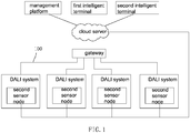
- the intelligent lighting control system based on the Internet of Things in the present invention comprises a gateway, a plurality of DALI systems, a cloud server connected to the gateway, a plurality of intelligent terminals for connecting to the cloud server and a management platform connected to the cloud server.
- Each DALI system comprises a DALI bus 100 connected to the gateway and each DALI bus is provided with a power node, a plurality of execution nodes, a plurality of control nodes and a plurality of first sensor nodes, and a plurality of second sensor nodes.
- the number of execution nodes on each DALI bus ranges from 1 to 64, which means that there can be up to 256 execution nodes under a single gateway.
- the power node is LED driving power supply
- the execution node is LED lamp
- the control node is control panel
- the first sensor node is photosensitive sensor, human proximity sensor, infrared sensor, etc.
- the second sensor node is temperature sensor, humidity sensor, WIFI probe, illumination sensor, etc.
- the second sensor node on each DALI bus is directly connected to the cloud server, so that the detection data of the second sensor node can be directly sent to the cloud server to facilitate the cloud server to realize a specific control function after performing analysis operations based on the detection data of the second sensor node.
- the intelligent terminal can perform data interaction with any node in any DALI system under the gateway, that is, the intelligent terminal can perform program setting and command manipulation on any node under the gateway.
- the management platform is used for information input and information storage.
- the picture information and the user account information of lamps, and the like can be input through the management platform.
- the first intelligent terminal is configured to map each execution node under the gateway to a layout made according to the actual position of each lamp, that is to say, to map each lamp controlled under the gateway to a layout made according to the actual position of each lamp.
- the second intelligent terminal is configured to set timing for any node under the gateway, so that the LED driving power source, LED lamp, and various sensors can be turned on or off as needed.
- the first intelligent terminal and the second intelligent terminal can group each execution node under the gateway, that is, all the LED lamps under the gateway can be grouped by the first intelligent terminal or the second intelligent terminal, and the first intelligent terminal and the second intelligent terminal can also perform function configuration on each control node under the gateway.
- the control node is a control panel, and the control panel is provided with a plurality of buttons, so that the first and the second intelligent terminal can perform function configuration for each button on the control panel.
- the lamps under the gateway are grouped by the first intelligent terminal or the second intelligent terminal, the lamps in one group can all be lamps in the same DALI system or include lamps in different DALI systems. Thus, when the lamps in each group contain lamps in different DALI system, cross-bus control is realized. Any button on each control panel can be configured to control any group and realize any control function.
- the grouping of the lamps under the gateway and the function configuration of the buttons on the control panel can be realized through the human-computer interaction interface on the intelligent terminal, and the grouping and function configuration are conventional technologies in the field, which will not be specifically described herein.
- the first sensor node on the DALI bus has two working modes, a stand-alone mode and a system mode.
- stand-alone mode the first sensor node is powered by the LED driving power supply on the DALI bus to which it is connected.
- system mode since all DALI buses are connected to the gateway, the first sensor node can be powered without using the LED driving power supply under its own gateway, and the first sensor node can be powered by the LED driving power supply on other DALI buses under the gateway, so that the LED driving power supply on the DALI bus, where the first sensor node is located, can be cut off, that is, in system mode, the LED driving power supply on a DALI bus can supply power to the first sensor node on all DALI buses under the gateway, which eliminates the need to turn on the LED driving power supply on each DALI bus, reducing power consumption.
- the first step is to scan all the lamps under DALI gateway.
- each lamp will have a DALI address in DALI protocol. Different lamp can be identified by different DALI address.
- the lamps can be scanned through the human-computer interaction interface on the first intelligent terminal, so that after we scan each lamp, when we select a lamp, we can get the DALI address of the lamp selected.
- the gateway in the present invention includes control module, WIFI module, Ethernet module, input module, and alarm module.
- the WIFI module, Ethernet module, input module and alarm module are all electrically connected with the control module.
- the main control chip of the gateway contains the control module described above; the input module is any device that can send signals to the control module by human operation. In this embodiment, the input module is a button.
- the input module can also be a sound sensor, an infrared sensor, a touch sensor, etc.;
- the WIFI module is used for gateway to connect WIFI network, and Ethernet module is used for gateway to connect Ethernet;
- the alarm module can be buzzer, acousto-optic alarm and other alarm devices.
- the intelligent device is a smart phone or a computer, in which an application for implementing the control functions required in this embodiment is installed.
- a method for synchronizing the MAC address of the WIFI module and the Ethernet module on the gateway includes the following steps:
Landscapes
- Engineering & Computer Science (AREA)
- Signal Processing (AREA)
- Computer Networks & Wireless Communication (AREA)
- Automation & Control Theory (AREA)
- Computing Systems (AREA)
- Health & Medical Sciences (AREA)
- General Health & Medical Sciences (AREA)
- Medical Informatics (AREA)
- Physics & Mathematics (AREA)
- General Physics & Mathematics (AREA)
- Multimedia (AREA)
- Circuit Arrangement For Electric Light Sources In General (AREA)
- Selective Calling Equipment (AREA)
Applications Claiming Priority (1)
| Application Number | Priority Date | Filing Date | Title |
|---|---|---|---|
| CN201811433479.2A CN109788605A (zh) | 2018-11-28 | 2018-11-28 | 基于物联网的智能照明控制系统 |
Publications (1)
| Publication Number | Publication Date |
|---|---|
| EP3661332A1 true EP3661332A1 (fr) | 2020-06-03 |
Family
ID=66496066
Family Applications (1)
| Application Number | Title | Priority Date | Filing Date |
|---|---|---|---|
| EP19211333.0A Withdrawn EP3661332A1 (fr) | 2018-11-28 | 2019-11-25 | Système de commande d'éclairage basé sur un serveur dans le cloud |
Country Status (3)
| Country | Link |
|---|---|
| US (1) | US11150619B2 (fr) |
| EP (1) | EP3661332A1 (fr) |
| CN (1) | CN109788605A (fr) |
Families Citing this family (11)
| Publication number | Priority date | Publication date | Assignee | Title |
|---|---|---|---|---|
| CN110351169B (zh) | 2019-09-06 | 2019-12-13 | 珠海格力电器股份有限公司 | 一种对设备进行绑定的方法和装置 |
| CN111314453A (zh) * | 2020-02-10 | 2020-06-19 | 上海赛艾吉智能科技有限公司 | 一种基于物联网的智能控制系统及运行方法 |
| CN111901951B (zh) * | 2020-07-28 | 2023-03-24 | 众盒智能科技(上海)有限公司 | Rdm灯具自动写址系统及方法 |
| CN112565451A (zh) * | 2020-12-18 | 2021-03-26 | 北京首都机场节能技术服务有限公司 | 一种dali网关及dali灯具控制系统 |
| CN112566327A (zh) * | 2020-12-30 | 2021-03-26 | 苏州佩林网络科技有限公司 | 智能灯具控制系统 |
| CN112672458A (zh) * | 2021-01-02 | 2021-04-16 | 南京普天大唐信息电子有限公司 | 一种快速部署智慧路灯物联网的方法及系统 |
| CN112804801A (zh) * | 2021-02-05 | 2021-05-14 | 南京美加杰智能科技有限公司 | 一种基于DALI和LoRaWAN的照明控制系统 |
| CN113709793A (zh) * | 2021-08-10 | 2021-11-26 | 广东睿住智能科技有限公司 | 智能灯的配网测试方法和系统 |
| CN114513496B (zh) * | 2021-12-29 | 2024-02-13 | 杭州深渡科技有限公司 | 一种智能灯具的控制方法、系统、装置和介质 |
| CN114629780A (zh) * | 2022-03-02 | 2022-06-14 | 安徽新中新华科电子有限公司 | 一种ic卡总线传输隔离系统及传输隔离方法 |
| CN119004726B (zh) * | 2024-10-21 | 2025-02-14 | 非凡士智能科技(苏州)有限公司 | 基于物联网灯具系统生成部署位置地图的方法和装置 |
Citations (9)
| Publication number | Priority date | Publication date | Assignee | Title |
|---|---|---|---|---|
| EP2490509A2 (fr) * | 2011-02-18 | 2012-08-22 | Samsung LED Co., Ltd. | Appareil et procédé pour commander un éclairage sur la base d'une communication DALI |
| EP2797391A1 (fr) * | 2013-02-20 | 2014-10-29 | Panasonic Intellectual Property Corporation of America | Programme et procédé de commande d'un terminal d'information portable |
| WO2015112637A1 (fr) * | 2014-01-21 | 2015-07-30 | Xicato, Inc. | Passerelle de communications a acces multiples d'eclairage a base de diodes electroluminescentes (led) |
| US20150331969A1 (en) * | 2014-05-15 | 2015-11-19 | Kenall Manufacturing Company | Systems and methods for providing a lighting control system layout for a site |
| DE102015201434A1 (de) * | 2015-01-28 | 2016-07-28 | Zumtobel Lighting Gmbh | Verfahren zum Betreiben von Geräten in einem Beleuchtungssystem |
| US20160323979A1 (en) * | 2015-04-29 | 2016-11-03 | Radiant Opto-Electronics Corporation | Lamp control system and control system |
| WO2017093559A1 (fr) * | 2015-12-03 | 2017-06-08 | Robert Bosch Gmbh | Système de détection et d'éclairage intelligent et procédé s'y rapportant |
| US9686842B1 (en) * | 2016-03-10 | 2017-06-20 | Gooee Limited | Universal smart lighting gateway |
| GB2559321A (en) * | 2017-01-10 | 2018-08-08 | Hoare Lea Llp | Graphical lighting control system |
Family Cites Families (16)
| Publication number | Priority date | Publication date | Assignee | Title |
|---|---|---|---|---|
| US9860965B2 (en) * | 2006-03-28 | 2018-01-02 | Wireless Environment, Llc | Cloud connected lighting system |
| US20170257257A1 (en) * | 2008-08-11 | 2017-09-07 | Paul DAWES | Coordinated control of connected devices in a premise |
| CN102625554B (zh) * | 2012-03-20 | 2014-01-29 | 浙江大学 | 一种分布式dali灯光照明控制系统及其方法 |
| US9596737B2 (en) * | 2013-07-02 | 2017-03-14 | Xicato, Inc. | Multi-port LED-based lighting communications gateway |
| CA2926260C (fr) * | 2013-10-10 | 2023-01-24 | Digital Lumens Incorporated | Procedes, systemes, et appareil pour un eclairage intelligent |
| CN104797032A (zh) * | 2014-01-18 | 2015-07-22 | 杜月林 | 一种基于物联网技术的led智能照明控制系统的实现方法 |
| CN104090953A (zh) * | 2014-07-04 | 2014-10-08 | 广东凯乐斯光电科技有限公司 | 一种led灯在虚拟显示终端的地图显示方法及装置 |
| US10542118B2 (en) * | 2015-09-24 | 2020-01-21 | Intel Corporation | Facilitating dynamic filtering and local and/or remote processing of data based on privacy policies and/or user preferences |
| US10637678B2 (en) * | 2015-09-24 | 2020-04-28 | Intel Corporation | Facilitating portable, reusable, and shareable internet of things (IoT)-based services and resources |
| US10715599B2 (en) * | 2015-11-30 | 2020-07-14 | Verizon Patent And Licensing, Inc. | Internet of things (IoT) platform and application framework |
| US20210157312A1 (en) * | 2016-05-09 | 2021-05-27 | Strong Force Iot Portfolio 2016, Llc | Intelligent vibration digital twin systems and methods for industrial environments |
| JP2019525536A (ja) * | 2016-06-22 | 2019-09-05 | ソラア インコーポレーテッドSoraa Inc. | 知能ネットワークに用いる知能モジュール |
| US9860677B1 (en) * | 2016-09-30 | 2018-01-02 | Intel Corporation | Internet-of-things gateway coordination |
| CN107063266A (zh) * | 2017-05-05 | 2017-08-18 | 江苏易恩特机电设备有限公司 | 基于室内led灯和智能手机摄像头实现室内定位的方法 |
| US11132881B2 (en) * | 2018-05-08 | 2021-09-28 | Amazon Technologies, Inc. | Electronic devices capable of communicating over multiple networks |
| US10791607B1 (en) * | 2018-08-17 | 2020-09-29 | Amazon Technologies, Inc. | Configuring and controlling light emitters |
-
2018
- 2018-11-28 CN CN201811433479.2A patent/CN109788605A/zh active Pending
-
2019
- 2019-11-21 US US16/691,263 patent/US11150619B2/en active Active
- 2019-11-25 EP EP19211333.0A patent/EP3661332A1/fr not_active Withdrawn
Patent Citations (9)
| Publication number | Priority date | Publication date | Assignee | Title |
|---|---|---|---|---|
| EP2490509A2 (fr) * | 2011-02-18 | 2012-08-22 | Samsung LED Co., Ltd. | Appareil et procédé pour commander un éclairage sur la base d'une communication DALI |
| EP2797391A1 (fr) * | 2013-02-20 | 2014-10-29 | Panasonic Intellectual Property Corporation of America | Programme et procédé de commande d'un terminal d'information portable |
| WO2015112637A1 (fr) * | 2014-01-21 | 2015-07-30 | Xicato, Inc. | Passerelle de communications a acces multiples d'eclairage a base de diodes electroluminescentes (led) |
| US20150331969A1 (en) * | 2014-05-15 | 2015-11-19 | Kenall Manufacturing Company | Systems and methods for providing a lighting control system layout for a site |
| DE102015201434A1 (de) * | 2015-01-28 | 2016-07-28 | Zumtobel Lighting Gmbh | Verfahren zum Betreiben von Geräten in einem Beleuchtungssystem |
| US20160323979A1 (en) * | 2015-04-29 | 2016-11-03 | Radiant Opto-Electronics Corporation | Lamp control system and control system |
| WO2017093559A1 (fr) * | 2015-12-03 | 2017-06-08 | Robert Bosch Gmbh | Système de détection et d'éclairage intelligent et procédé s'y rapportant |
| US9686842B1 (en) * | 2016-03-10 | 2017-06-20 | Gooee Limited | Universal smart lighting gateway |
| GB2559321A (en) * | 2017-01-10 | 2018-08-08 | Hoare Lea Llp | Graphical lighting control system |
Also Published As
| Publication number | Publication date |
|---|---|
| US11150619B2 (en) | 2021-10-19 |
| CN109788605A (zh) | 2019-05-21 |
| US20200166903A1 (en) | 2020-05-28 |
Similar Documents
| Publication | Publication Date | Title |
|---|---|---|
| US11150619B2 (en) | Intelligent lighting control system based on internet of things | |
| CN109413515B (zh) | 设备控制方法、装置、移动终端及服务器 | |
| US20050102040A1 (en) | Radio frequency lighting control system programming device and method | |
| EP1540997A2 (fr) | Systeme d'exploitation general | |
| CN104468178B (zh) | 用于在操作环境内配置控制系统的方法及设备 | |
| CN111052009B (zh) | 控制系统、控制器和控制方法 | |
| JP2021166394A (ja) | 通信ネットワークを試験するための、マシン可読コードを利用する方法、モバイルデバイス及び非一時的なコンピュータ可読記憶媒体 | |
| CN103888983B (zh) | 终端wifi工作模式自动切换方法和系统 | |
| CN108700886A (zh) | 一种控制终端的控制方法及控制终端 | |
| CN117879986A (zh) | 基于互联互通网络的控制方法、装置、设备及存储介质 | |
| US20190123958A1 (en) | Installation Support Device and Method for Installation Process Support for an Automation System | |
| KR102213312B1 (ko) | 조명 기구, 단말기, 조명 시스템, 정보 단말, 조명 기구의 페어링 방법 및 프로그램 | |
| US11223961B2 (en) | Configuration method of wireless network system, configuration terminal and configuration system | |
| CN112911564A (zh) | 一种多协议并发的蓝牙智能系统 | |
| CN208015725U (zh) | 多联机系统 | |
| US11223600B2 (en) | Mac address synchronization method | |
| CN109683960B (zh) | 一种电口模块的寄存器配置方法及其电口模块 | |
| CN112881902A (zh) | 一种显示芯片测试设备 | |
| JPH01141440A (ja) | 伝送装置におけるアドレス設定装置 | |
| US20210144835A1 (en) | System using handheld device for programming lighting instruments | |
| CN118348841B (zh) | 一种物联设备监控方法、装置以及微模块数据中心 | |
| US20250060714A1 (en) | Device control method | |
| CN114666396B (zh) | 节点控制方法、主控节点及节点 | |
| CN110726208A (zh) | 一种多台空调器的控制方法、装置、终端及可读存储介质 | |
| CN113033725A (zh) | Odn资源信息管理方法、装置及存储介质 |
Legal Events
| Date | Code | Title | Description |
|---|---|---|---|
| PUAI | Public reference made under article 153(3) epc to a published international application that has entered the european phase |
Free format text: ORIGINAL CODE: 0009012 |
|
| STAA | Information on the status of an ep patent application or granted ep patent |
Free format text: STATUS: THE APPLICATION HAS BEEN PUBLISHED |
|
| AK | Designated contracting states |
Kind code of ref document: A1 Designated state(s): AL AT BE BG CH CY CZ DE DK EE ES FI FR GB GR HR HU IE IS IT LI LT LU LV MC MK MT NL NO PL PT RO RS SE SI SK SM TR |
|
| AX | Request for extension of the european patent |
Extension state: BA ME |
|
| RIN1 | Information on inventor provided before grant (corrected) |
Inventor name: ZHANG, JIAN |
|
| STAA | Information on the status of an ep patent application or granted ep patent |
Free format text: STATUS: THE APPLICATION IS DEEMED TO BE WITHDRAWN |
|
| 18D | Application deemed to be withdrawn |
Effective date: 20201204 |