EP3661747B1 - Procédé pour le collage de gomme et adhésif pour le collage de gomme - Google Patents
Procédé pour le collage de gomme et adhésif pour le collage de gomme Download PDFInfo
- Publication number
- EP3661747B1 EP3661747B1 EP18758548.4A EP18758548A EP3661747B1 EP 3661747 B1 EP3661747 B1 EP 3661747B1 EP 18758548 A EP18758548 A EP 18758548A EP 3661747 B1 EP3661747 B1 EP 3661747B1
- Authority
- EP
- European Patent Office
- Prior art keywords
- adhesive
- permanently elastic
- conveyor belt
- strength
- belt
- Prior art date
- Legal status (The legal status is an assumption and is not a legal conclusion. Google has not performed a legal analysis and makes no representation as to the accuracy of the status listed.)
- Active
Links
Images













Classifications
-
- B—PERFORMING OPERATIONS; TRANSPORTING
- B32—LAYERED PRODUCTS
- B32B—LAYERED PRODUCTS, i.e. PRODUCTS BUILT-UP OF STRATA OF FLAT OR NON-FLAT, e.g. CELLULAR OR HONEYCOMB, FORM
- B32B37/00—Methods or apparatus for laminating, e.g. by curing or by ultrasonic bonding
- B32B37/10—Methods or apparatus for laminating, e.g. by curing or by ultrasonic bonding characterised by the pressing technique, e.g. using action of vacuum or fluid pressure
-
- B—PERFORMING OPERATIONS; TRANSPORTING
- B29—WORKING OF PLASTICS; WORKING OF SUBSTANCES IN A PLASTIC STATE IN GENERAL
- B29C—SHAPING OR JOINING OF PLASTICS; SHAPING OF MATERIAL IN A PLASTIC STATE, NOT OTHERWISE PROVIDED FOR; AFTER-TREATMENT OF THE SHAPED PRODUCTS, e.g. REPAIRING
- B29C63/00—Lining or sheathing, i.e. applying preformed layers or sheathings of plastics; Apparatus therefor
- B29C63/02—Lining or sheathing, i.e. applying preformed layers or sheathings of plastics; Apparatus therefor using sheet or web-like material
-
- B—PERFORMING OPERATIONS; TRANSPORTING
- B29—WORKING OF PLASTICS; WORKING OF SUBSTANCES IN A PLASTIC STATE IN GENERAL
- B29C—SHAPING OR JOINING OF PLASTICS; SHAPING OF MATERIAL IN A PLASTIC STATE, NOT OTHERWISE PROVIDED FOR; AFTER-TREATMENT OF THE SHAPED PRODUCTS, e.g. REPAIRING
- B29C63/00—Lining or sheathing, i.e. applying preformed layers or sheathings of plastics; Apparatus therefor
- B29C63/48—Preparation of the surfaces
-
- B—PERFORMING OPERATIONS; TRANSPORTING
- B29—WORKING OF PLASTICS; WORKING OF SUBSTANCES IN A PLASTIC STATE IN GENERAL
- B29C—SHAPING OR JOINING OF PLASTICS; SHAPING OF MATERIAL IN A PLASTIC STATE, NOT OTHERWISE PROVIDED FOR; AFTER-TREATMENT OF THE SHAPED PRODUCTS, e.g. REPAIRING
- B29C65/00—Joining or sealing of preformed parts, e.g. welding of plastics materials; Apparatus therefor
- B29C65/48—Joining or sealing of preformed parts, e.g. welding of plastics materials; Apparatus therefor using adhesives, i.e. using supplementary joining material; solvent bonding
- B29C65/4805—Joining or sealing of preformed parts, e.g. welding of plastics materials; Apparatus therefor using adhesives, i.e. using supplementary joining material; solvent bonding characterised by the type of adhesives
- B29C65/483—Reactive adhesives, e.g. chemically curing adhesives
-
- B—PERFORMING OPERATIONS; TRANSPORTING
- B29—WORKING OF PLASTICS; WORKING OF SUBSTANCES IN A PLASTIC STATE IN GENERAL
- B29C—SHAPING OR JOINING OF PLASTICS; SHAPING OF MATERIAL IN A PLASTIC STATE, NOT OTHERWISE PROVIDED FOR; AFTER-TREATMENT OF THE SHAPED PRODUCTS, e.g. REPAIRING
- B29C65/00—Joining or sealing of preformed parts, e.g. welding of plastics materials; Apparatus therefor
- B29C65/48—Joining or sealing of preformed parts, e.g. welding of plastics materials; Apparatus therefor using adhesives, i.e. using supplementary joining material; solvent bonding
- B29C65/4805—Joining or sealing of preformed parts, e.g. welding of plastics materials; Apparatus therefor using adhesives, i.e. using supplementary joining material; solvent bonding characterised by the type of adhesives
- B29C65/483—Reactive adhesives, e.g. chemically curing adhesives
- B29C65/485—Multi-component adhesives, i.e. chemically curing as a result of the mixing of said multi-components
-
- B—PERFORMING OPERATIONS; TRANSPORTING
- B29—WORKING OF PLASTICS; WORKING OF SUBSTANCES IN A PLASTIC STATE IN GENERAL
- B29C—SHAPING OR JOINING OF PLASTICS; SHAPING OF MATERIAL IN A PLASTIC STATE, NOT OTHERWISE PROVIDED FOR; AFTER-TREATMENT OF THE SHAPED PRODUCTS, e.g. REPAIRING
- B29C65/00—Joining or sealing of preformed parts, e.g. welding of plastics materials; Apparatus therefor
- B29C65/48—Joining or sealing of preformed parts, e.g. welding of plastics materials; Apparatus therefor using adhesives, i.e. using supplementary joining material; solvent bonding
- B29C65/50—Joining or sealing of preformed parts, e.g. welding of plastics materials; Apparatus therefor using adhesives, i.e. using supplementary joining material; solvent bonding using adhesive tape, e.g. thermoplastic tape; using threads or the like
- B29C65/5042—Joining or sealing of preformed parts, e.g. welding of plastics materials; Apparatus therefor using adhesives, i.e. using supplementary joining material; solvent bonding using adhesive tape, e.g. thermoplastic tape; using threads or the like covering both elements to be joined
- B29C65/505—Joining or sealing of preformed parts, e.g. welding of plastics materials; Apparatus therefor using adhesives, i.e. using supplementary joining material; solvent bonding using adhesive tape, e.g. thermoplastic tape; using threads or the like covering both elements to be joined and placed in a recess formed in the parts to be joined, e.g. in order to obtain a continuous surface
-
- B—PERFORMING OPERATIONS; TRANSPORTING
- B29—WORKING OF PLASTICS; WORKING OF SUBSTANCES IN A PLASTIC STATE IN GENERAL
- B29C—SHAPING OR JOINING OF PLASTICS; SHAPING OF MATERIAL IN A PLASTIC STATE, NOT OTHERWISE PROVIDED FOR; AFTER-TREATMENT OF THE SHAPED PRODUCTS, e.g. REPAIRING
- B29C65/00—Joining or sealing of preformed parts, e.g. welding of plastics materials; Apparatus therefor
- B29C65/48—Joining or sealing of preformed parts, e.g. welding of plastics materials; Apparatus therefor using adhesives, i.e. using supplementary joining material; solvent bonding
- B29C65/50—Joining or sealing of preformed parts, e.g. welding of plastics materials; Apparatus therefor using adhesives, i.e. using supplementary joining material; solvent bonding using adhesive tape, e.g. thermoplastic tape; using threads or the like
- B29C65/5064—Joining or sealing of preformed parts, e.g. welding of plastics materials; Apparatus therefor using adhesives, i.e. using supplementary joining material; solvent bonding using adhesive tape, e.g. thermoplastic tape; using threads or the like of particular form, e.g. being C-shaped, T-shaped
- B29C65/5071—Joining or sealing of preformed parts, e.g. welding of plastics materials; Apparatus therefor using adhesives, i.e. using supplementary joining material; solvent bonding using adhesive tape, e.g. thermoplastic tape; using threads or the like of particular form, e.g. being C-shaped, T-shaped and being composed by one single element
-
- B—PERFORMING OPERATIONS; TRANSPORTING
- B29—WORKING OF PLASTICS; WORKING OF SUBSTANCES IN A PLASTIC STATE IN GENERAL
- B29C—SHAPING OR JOINING OF PLASTICS; SHAPING OF MATERIAL IN A PLASTIC STATE, NOT OTHERWISE PROVIDED FOR; AFTER-TREATMENT OF THE SHAPED PRODUCTS, e.g. REPAIRING
- B29C65/00—Joining or sealing of preformed parts, e.g. welding of plastics materials; Apparatus therefor
- B29C65/48—Joining or sealing of preformed parts, e.g. welding of plastics materials; Apparatus therefor using adhesives, i.e. using supplementary joining material; solvent bonding
- B29C65/52—Joining or sealing of preformed parts, e.g. welding of plastics materials; Apparatus therefor using adhesives, i.e. using supplementary joining material; solvent bonding characterised by the way of applying the adhesive
- B29C65/524—Joining or sealing of preformed parts, e.g. welding of plastics materials; Apparatus therefor using adhesives, i.e. using supplementary joining material; solvent bonding characterised by the way of applying the adhesive by applying the adhesive from an outlet device in contact with, or almost in contact with, the surface of the part to be joined
-
- B—PERFORMING OPERATIONS; TRANSPORTING
- B29—WORKING OF PLASTICS; WORKING OF SUBSTANCES IN A PLASTIC STATE IN GENERAL
- B29C—SHAPING OR JOINING OF PLASTICS; SHAPING OF MATERIAL IN A PLASTIC STATE, NOT OTHERWISE PROVIDED FOR; AFTER-TREATMENT OF THE SHAPED PRODUCTS, e.g. REPAIRING
- B29C65/00—Joining or sealing of preformed parts, e.g. welding of plastics materials; Apparatus therefor
- B29C65/78—Means for handling the parts to be joined, e.g. for making containers or hollow articles, e.g. means for handling sheets, plates, web-like materials, tubular articles, hollow articles or elements to be joined therewith; Means for discharging the joined articles from the joining apparatus
- B29C65/7841—Holding or clamping means for handling purposes
-
- B—PERFORMING OPERATIONS; TRANSPORTING
- B29—WORKING OF PLASTICS; WORKING OF SUBSTANCES IN A PLASTIC STATE IN GENERAL
- B29C—SHAPING OR JOINING OF PLASTICS; SHAPING OF MATERIAL IN A PLASTIC STATE, NOT OTHERWISE PROVIDED FOR; AFTER-TREATMENT OF THE SHAPED PRODUCTS, e.g. REPAIRING
- B29C66/00—General aspects of processes or apparatus for joining preformed parts
- B29C66/01—General aspects dealing with the joint area or with the area to be joined
- B29C66/02—Preparation of the material, in the area to be joined, prior to joining or welding
- B29C66/022—Mechanical pre-treatments, e.g. reshaping
- B29C66/0224—Mechanical pre-treatments, e.g. reshaping with removal of material
- B29C66/02241—Cutting, e.g. by using waterjets, or sawing
-
- B—PERFORMING OPERATIONS; TRANSPORTING
- B29—WORKING OF PLASTICS; WORKING OF SUBSTANCES IN A PLASTIC STATE IN GENERAL
- B29C—SHAPING OR JOINING OF PLASTICS; SHAPING OF MATERIAL IN A PLASTIC STATE, NOT OTHERWISE PROVIDED FOR; AFTER-TREATMENT OF THE SHAPED PRODUCTS, e.g. REPAIRING
- B29C66/00—General aspects of processes or apparatus for joining preformed parts
- B29C66/01—General aspects dealing with the joint area or with the area to be joined
- B29C66/02—Preparation of the material, in the area to be joined, prior to joining or welding
- B29C66/022—Mechanical pre-treatments, e.g. reshaping
- B29C66/0224—Mechanical pre-treatments, e.g. reshaping with removal of material
- B29C66/02245—Abrading, e.g. grinding, sanding, sandblasting or scraping
-
- B—PERFORMING OPERATIONS; TRANSPORTING
- B29—WORKING OF PLASTICS; WORKING OF SUBSTANCES IN A PLASTIC STATE IN GENERAL
- B29C—SHAPING OR JOINING OF PLASTICS; SHAPING OF MATERIAL IN A PLASTIC STATE, NOT OTHERWISE PROVIDED FOR; AFTER-TREATMENT OF THE SHAPED PRODUCTS, e.g. REPAIRING
- B29C66/00—General aspects of processes or apparatus for joining preformed parts
- B29C66/01—General aspects dealing with the joint area or with the area to be joined
- B29C66/05—Particular design of joint configurations
- B29C66/10—Particular design of joint configurations particular design of the joint cross-sections
- B29C66/11—Joint cross-sections comprising a single joint-segment, i.e. one of the parts to be joined comprising a single joint-segment in the joint cross-section
- B29C66/114—Single butt joints
- B29C66/1142—Single butt to butt joints
-
- B—PERFORMING OPERATIONS; TRANSPORTING
- B29—WORKING OF PLASTICS; WORKING OF SUBSTANCES IN A PLASTIC STATE IN GENERAL
- B29C—SHAPING OR JOINING OF PLASTICS; SHAPING OF MATERIAL IN A PLASTIC STATE, NOT OTHERWISE PROVIDED FOR; AFTER-TREATMENT OF THE SHAPED PRODUCTS, e.g. REPAIRING
- B29C66/00—General aspects of processes or apparatus for joining preformed parts
- B29C66/01—General aspects dealing with the joint area or with the area to be joined
- B29C66/05—Particular design of joint configurations
- B29C66/10—Particular design of joint configurations particular design of the joint cross-sections
- B29C66/12—Joint cross-sections combining only two joint-segments; Tongue and groove joints; Tenon and mortise joints; Stepped joint cross-sections
- B29C66/128—Stepped joint cross-sections
- B29C66/1282—Stepped joint cross-sections comprising at least one overlap joint-segment
- B29C66/12821—Stepped joint cross-sections comprising at least one overlap joint-segment comprising at least two overlap joint-segments
- B29C66/12822—Stepped joint cross-sections comprising at least one overlap joint-segment comprising at least two overlap joint-segments comprising at least three overlap joint-segments
-
- B—PERFORMING OPERATIONS; TRANSPORTING
- B29—WORKING OF PLASTICS; WORKING OF SUBSTANCES IN A PLASTIC STATE IN GENERAL
- B29C—SHAPING OR JOINING OF PLASTICS; SHAPING OF MATERIAL IN A PLASTIC STATE, NOT OTHERWISE PROVIDED FOR; AFTER-TREATMENT OF THE SHAPED PRODUCTS, e.g. REPAIRING
- B29C66/00—General aspects of processes or apparatus for joining preformed parts
- B29C66/01—General aspects dealing with the joint area or with the area to be joined
- B29C66/05—Particular design of joint configurations
- B29C66/10—Particular design of joint configurations particular design of the joint cross-sections
- B29C66/12—Joint cross-sections combining only two joint-segments; Tongue and groove joints; Tenon and mortise joints; Stepped joint cross-sections
- B29C66/128—Stepped joint cross-sections
- B29C66/1284—Stepped joint cross-sections comprising at least one butt joint-segment
- B29C66/12841—Stepped joint cross-sections comprising at least one butt joint-segment comprising at least two butt joint-segments
- B29C66/12842—Stepped joint cross-sections comprising at least one butt joint-segment comprising at least two butt joint-segments comprising at least three butt joint-segments
-
- B—PERFORMING OPERATIONS; TRANSPORTING
- B29—WORKING OF PLASTICS; WORKING OF SUBSTANCES IN A PLASTIC STATE IN GENERAL
- B29C—SHAPING OR JOINING OF PLASTICS; SHAPING OF MATERIAL IN A PLASTIC STATE, NOT OTHERWISE PROVIDED FOR; AFTER-TREATMENT OF THE SHAPED PRODUCTS, e.g. REPAIRING
- B29C66/00—General aspects of processes or apparatus for joining preformed parts
- B29C66/01—General aspects dealing with the joint area or with the area to be joined
- B29C66/05—Particular design of joint configurations
- B29C66/10—Particular design of joint configurations particular design of the joint cross-sections
- B29C66/14—Particular design of joint configurations particular design of the joint cross-sections the joint having the same thickness as the thickness of the parts to be joined
-
- B—PERFORMING OPERATIONS; TRANSPORTING
- B29—WORKING OF PLASTICS; WORKING OF SUBSTANCES IN A PLASTIC STATE IN GENERAL
- B29C—SHAPING OR JOINING OF PLASTICS; SHAPING OF MATERIAL IN A PLASTIC STATE, NOT OTHERWISE PROVIDED FOR; AFTER-TREATMENT OF THE SHAPED PRODUCTS, e.g. REPAIRING
- B29C66/00—General aspects of processes or apparatus for joining preformed parts
- B29C66/01—General aspects dealing with the joint area or with the area to be joined
- B29C66/05—Particular design of joint configurations
- B29C66/20—Particular design of joint configurations particular design of the joint lines, e.g. of the weld lines
- B29C66/22—Particular design of joint configurations particular design of the joint lines, e.g. of the weld lines said joint lines being in the form of recurring patterns
- B29C66/225—Particular design of joint configurations particular design of the joint lines, e.g. of the weld lines said joint lines being in the form of recurring patterns being castellated, e.g. in the form of a square wave or of a rectangular wave
-
- B—PERFORMING OPERATIONS; TRANSPORTING
- B29—WORKING OF PLASTICS; WORKING OF SUBSTANCES IN A PLASTIC STATE IN GENERAL
- B29C—SHAPING OR JOINING OF PLASTICS; SHAPING OF MATERIAL IN A PLASTIC STATE, NOT OTHERWISE PROVIDED FOR; AFTER-TREATMENT OF THE SHAPED PRODUCTS, e.g. REPAIRING
- B29C66/00—General aspects of processes or apparatus for joining preformed parts
- B29C66/01—General aspects dealing with the joint area or with the area to be joined
- B29C66/05—Particular design of joint configurations
- B29C66/303—Particular design of joint configurations the joint involving an anchoring effect
- B29C66/3032—Particular design of joint configurations the joint involving an anchoring effect making use of protrusions or cavities belonging to at least one of the parts to be joined
- B29C66/30321—Particular design of joint configurations the joint involving an anchoring effect making use of protrusions or cavities belonging to at least one of the parts to be joined making use of protrusions belonging to at least one of the parts to be joined
- B29C66/30322—Particular design of joint configurations the joint involving an anchoring effect making use of protrusions or cavities belonging to at least one of the parts to be joined making use of protrusions belonging to at least one of the parts to be joined in the form of rugosity
-
- B—PERFORMING OPERATIONS; TRANSPORTING
- B29—WORKING OF PLASTICS; WORKING OF SUBSTANCES IN A PLASTIC STATE IN GENERAL
- B29C—SHAPING OR JOINING OF PLASTICS; SHAPING OF MATERIAL IN A PLASTIC STATE, NOT OTHERWISE PROVIDED FOR; AFTER-TREATMENT OF THE SHAPED PRODUCTS, e.g. REPAIRING
- B29C66/00—General aspects of processes or apparatus for joining preformed parts
- B29C66/40—General aspects of joining substantially flat articles, e.g. plates, sheets or web-like materials; Making flat seams in tubular or hollow articles; Joining single elements to substantially flat surfaces
- B29C66/41—Joining substantially flat articles ; Making flat seams in tubular or hollow articles
- B29C66/43—Joining a relatively small portion of the surface of said articles
- B29C66/432—Joining a relatively small portion of the surface of said articles for making tubular articles or closed loops, e.g. by joining several sheets ; for making hollow articles or hollow preforms
- B29C66/4322—Joining a relatively small portion of the surface of said articles for making tubular articles or closed loops, e.g. by joining several sheets ; for making hollow articles or hollow preforms by joining a single sheet to itself
-
- B—PERFORMING OPERATIONS; TRANSPORTING
- B29—WORKING OF PLASTICS; WORKING OF SUBSTANCES IN A PLASTIC STATE IN GENERAL
- B29C—SHAPING OR JOINING OF PLASTICS; SHAPING OF MATERIAL IN A PLASTIC STATE, NOT OTHERWISE PROVIDED FOR; AFTER-TREATMENT OF THE SHAPED PRODUCTS, e.g. REPAIRING
- B29C66/00—General aspects of processes or apparatus for joining preformed parts
- B29C66/40—General aspects of joining substantially flat articles, e.g. plates, sheets or web-like materials; Making flat seams in tubular or hollow articles; Joining single elements to substantially flat surfaces
- B29C66/41—Joining substantially flat articles ; Making flat seams in tubular or hollow articles
- B29C66/43—Joining a relatively small portion of the surface of said articles
- B29C66/432—Joining a relatively small portion of the surface of said articles for making tubular articles or closed loops, e.g. by joining several sheets ; for making hollow articles or hollow preforms
- B29C66/4324—Joining a relatively small portion of the surface of said articles for making tubular articles or closed loops, e.g. by joining several sheets ; for making hollow articles or hollow preforms for making closed loops, e.g. belts
-
- B—PERFORMING OPERATIONS; TRANSPORTING
- B29—WORKING OF PLASTICS; WORKING OF SUBSTANCES IN A PLASTIC STATE IN GENERAL
- B29C—SHAPING OR JOINING OF PLASTICS; SHAPING OF MATERIAL IN A PLASTIC STATE, NOT OTHERWISE PROVIDED FOR; AFTER-TREATMENT OF THE SHAPED PRODUCTS, e.g. REPAIRING
- B29C66/00—General aspects of processes or apparatus for joining preformed parts
- B29C66/50—General aspects of joining tubular articles; General aspects of joining long products, i.e. bars or profiled elements; General aspects of joining single elements to tubular articles, hollow articles or bars; General aspects of joining several hollow-preforms to form hollow or tubular articles
- B29C66/51—Joining tubular articles, profiled elements or bars; Joining single elements to tubular articles, hollow articles or bars; Joining several hollow-preforms to form hollow or tubular articles
- B29C66/53—Joining single elements to tubular articles, hollow articles or bars
- B29C66/532—Joining single elements to the wall of tubular articles, hollow articles or bars
- B29C66/5326—Joining single elements to the wall of tubular articles, hollow articles or bars said single elements being substantially flat
-
- B—PERFORMING OPERATIONS; TRANSPORTING
- B29—WORKING OF PLASTICS; WORKING OF SUBSTANCES IN A PLASTIC STATE IN GENERAL
- B29C—SHAPING OR JOINING OF PLASTICS; SHAPING OF MATERIAL IN A PLASTIC STATE, NOT OTHERWISE PROVIDED FOR; AFTER-TREATMENT OF THE SHAPED PRODUCTS, e.g. REPAIRING
- B29C66/00—General aspects of processes or apparatus for joining preformed parts
- B29C66/70—General aspects of processes or apparatus for joining preformed parts characterised by the composition, physical properties or the structure of the material of the parts to be joined; Joining with non-plastics material
- B29C66/71—General aspects of processes or apparatus for joining preformed parts characterised by the composition, physical properties or the structure of the material of the parts to be joined; Joining with non-plastics material characterised by the composition of the plastics material of the parts to be joined
-
- B—PERFORMING OPERATIONS; TRANSPORTING
- B29—WORKING OF PLASTICS; WORKING OF SUBSTANCES IN A PLASTIC STATE IN GENERAL
- B29C—SHAPING OR JOINING OF PLASTICS; SHAPING OF MATERIAL IN A PLASTIC STATE, NOT OTHERWISE PROVIDED FOR; AFTER-TREATMENT OF THE SHAPED PRODUCTS, e.g. REPAIRING
- B29C66/00—General aspects of processes or apparatus for joining preformed parts
- B29C66/70—General aspects of processes or apparatus for joining preformed parts characterised by the composition, physical properties or the structure of the material of the parts to be joined; Joining with non-plastics material
- B29C66/72—General aspects of processes or apparatus for joining preformed parts characterised by the composition, physical properties or the structure of the material of the parts to be joined; Joining with non-plastics material characterised by the structure of the material of the parts to be joined
- B29C66/721—Fibre-reinforced materials
- B29C66/7212—Fibre-reinforced materials characterised by the composition of the fibres
-
- B—PERFORMING OPERATIONS; TRANSPORTING
- B29—WORKING OF PLASTICS; WORKING OF SUBSTANCES IN A PLASTIC STATE IN GENERAL
- B29C—SHAPING OR JOINING OF PLASTICS; SHAPING OF MATERIAL IN A PLASTIC STATE, NOT OTHERWISE PROVIDED FOR; AFTER-TREATMENT OF THE SHAPED PRODUCTS, e.g. REPAIRING
- B29C66/00—General aspects of processes or apparatus for joining preformed parts
- B29C66/70—General aspects of processes or apparatus for joining preformed parts characterised by the composition, physical properties or the structure of the material of the parts to be joined; Joining with non-plastics material
- B29C66/72—General aspects of processes or apparatus for joining preformed parts characterised by the composition, physical properties or the structure of the material of the parts to be joined; Joining with non-plastics material characterised by the structure of the material of the parts to be joined
- B29C66/721—Fibre-reinforced materials
- B29C66/7214—Fibre-reinforced materials characterised by the length of the fibres
- B29C66/72141—Fibres of continuous length
-
- B—PERFORMING OPERATIONS; TRANSPORTING
- B29—WORKING OF PLASTICS; WORKING OF SUBSTANCES IN A PLASTIC STATE IN GENERAL
- B29C—SHAPING OR JOINING OF PLASTICS; SHAPING OF MATERIAL IN A PLASTIC STATE, NOT OTHERWISE PROVIDED FOR; AFTER-TREATMENT OF THE SHAPED PRODUCTS, e.g. REPAIRING
- B29C66/00—General aspects of processes or apparatus for joining preformed parts
- B29C66/80—General aspects of machine operations or constructions and parts thereof
- B29C66/83—General aspects of machine operations or constructions and parts thereof characterised by the movement of the joining or pressing tools
- B29C66/836—Moving relative to and tangentially to the parts to be joined, e.g. transversely to the displacement of the parts to be joined, e.g. using a X-Y table
- B29C66/8362—Rollers, cylinders or drums moving relative to and tangentially to the parts to be joined
-
- B—PERFORMING OPERATIONS; TRANSPORTING
- B29—WORKING OF PLASTICS; WORKING OF SUBSTANCES IN A PLASTIC STATE IN GENERAL
- B29C—SHAPING OR JOINING OF PLASTICS; SHAPING OF MATERIAL IN A PLASTIC STATE, NOT OTHERWISE PROVIDED FOR; AFTER-TREATMENT OF THE SHAPED PRODUCTS, e.g. REPAIRING
- B29C66/00—General aspects of processes or apparatus for joining preformed parts
- B29C66/80—General aspects of machine operations or constructions and parts thereof
- B29C66/84—Specific machine types or machines suitable for specific applications
- B29C66/861—Hand-held tools
-
- B—PERFORMING OPERATIONS; TRANSPORTING
- B29—WORKING OF PLASTICS; WORKING OF SUBSTANCES IN A PLASTIC STATE IN GENERAL
- B29C—SHAPING OR JOINING OF PLASTICS; SHAPING OF MATERIAL IN A PLASTIC STATE, NOT OTHERWISE PROVIDED FOR; AFTER-TREATMENT OF THE SHAPED PRODUCTS, e.g. REPAIRING
- B29C66/00—General aspects of processes or apparatus for joining preformed parts
- B29C66/90—Measuring or controlling the joining process
- B29C66/91—Measuring or controlling the joining process by measuring or controlling the temperature, the heat or the thermal flux
- B29C66/919—Measuring or controlling the joining process by measuring or controlling the temperature, the heat or the thermal flux characterised by specific temperature, heat or thermal flux values or ranges
- B29C66/9192—Measuring or controlling the joining process by measuring or controlling the temperature, the heat or the thermal flux characterised by specific temperature, heat or thermal flux values or ranges in explicit relation to another variable, e.g. temperature diagrams
- B29C66/91951—Measuring or controlling the joining process by measuring or controlling the temperature, the heat or the thermal flux characterised by specific temperature, heat or thermal flux values or ranges in explicit relation to another variable, e.g. temperature diagrams in explicit relation to time, e.g. temperature-time diagrams
-
- B—PERFORMING OPERATIONS; TRANSPORTING
- B29—WORKING OF PLASTICS; WORKING OF SUBSTANCES IN A PLASTIC STATE IN GENERAL
- B29C—SHAPING OR JOINING OF PLASTICS; SHAPING OF MATERIAL IN A PLASTIC STATE, NOT OTHERWISE PROVIDED FOR; AFTER-TREATMENT OF THE SHAPED PRODUCTS, e.g. REPAIRING
- B29C73/00—Repairing of articles made from plastics or substances in a plastic state, e.g. of articles shaped or produced by using techniques covered by this subclass or subclass B29D
- B29C73/02—Repairing of articles made from plastics or substances in a plastic state, e.g. of articles shaped or produced by using techniques covered by this subclass or subclass B29D using liquid or paste-like material
-
- B—PERFORMING OPERATIONS; TRANSPORTING
- B32—LAYERED PRODUCTS
- B32B—LAYERED PRODUCTS, i.e. PRODUCTS BUILT-UP OF STRATA OF FLAT OR NON-FLAT, e.g. CELLULAR OR HONEYCOMB, FORM
- B32B37/00—Methods or apparatus for laminating, e.g. by curing or by ultrasonic bonding
- B32B37/12—Methods or apparatus for laminating, e.g. by curing or by ultrasonic bonding characterised by using adhesives
-
- C—CHEMISTRY; METALLURGY
- C08—ORGANIC MACROMOLECULAR COMPOUNDS; THEIR PREPARATION OR CHEMICAL WORKING-UP; COMPOSITIONS BASED THEREON
- C08G—MACROMOLECULAR COMPOUNDS OBTAINED OTHERWISE THAN BY REACTIONS ONLY INVOLVING UNSATURATED CARBON-TO-CARBON BONDS
- C08G18/00—Polymeric products of isocyanates or isothiocyanates
- C08G18/06—Polymeric products of isocyanates or isothiocyanates with compounds having active hydrogen
- C08G18/83—Chemically modified polymers
- C08G18/87—Chemically modified polymers by sulfur
-
- C—CHEMISTRY; METALLURGY
- C08—ORGANIC MACROMOLECULAR COMPOUNDS; THEIR PREPARATION OR CHEMICAL WORKING-UP; COMPOSITIONS BASED THEREON
- C08K—Use of inorganic or non-macromolecular organic substances as compounding ingredients
- C08K3/00—Use of inorganic substances as compounding ingredients
- C08K3/01—Use of inorganic substances as compounding ingredients characterized by their specific function
- C08K3/011—Crosslinking or vulcanising agents, e.g. accelerators
-
- C—CHEMISTRY; METALLURGY
- C09—DYES; PAINTS; POLISHES; NATURAL RESINS; ADHESIVES; COMPOSITIONS NOT OTHERWISE PROVIDED FOR; APPLICATIONS OF MATERIALS NOT OTHERWISE PROVIDED FOR
- C09J—ADHESIVES; NON-MECHANICAL ASPECTS OF ADHESIVE PROCESSES IN GENERAL; ADHESIVE PROCESSES NOT PROVIDED FOR ELSEWHERE; USE OF MATERIALS AS ADHESIVES
- C09J11/00—Features of adhesives not provided for in group C09J9/00, e.g. additives
- C09J11/02—Non-macromolecular additives
- C09J11/06—Non-macromolecular additives organic
-
- C—CHEMISTRY; METALLURGY
- C09—DYES; PAINTS; POLISHES; NATURAL RESINS; ADHESIVES; COMPOSITIONS NOT OTHERWISE PROVIDED FOR; APPLICATIONS OF MATERIALS NOT OTHERWISE PROVIDED FOR
- C09J—ADHESIVES; NON-MECHANICAL ASPECTS OF ADHESIVE PROCESSES IN GENERAL; ADHESIVE PROCESSES NOT PROVIDED FOR ELSEWHERE; USE OF MATERIALS AS ADHESIVES
- C09J175/00—Adhesives based on polyureas or polyurethanes; Adhesives based on derivatives of such polymers
-
- C—CHEMISTRY; METALLURGY
- C09—DYES; PAINTS; POLISHES; NATURAL RESINS; ADHESIVES; COMPOSITIONS NOT OTHERWISE PROVIDED FOR; APPLICATIONS OF MATERIALS NOT OTHERWISE PROVIDED FOR
- C09J—ADHESIVES; NON-MECHANICAL ASPECTS OF ADHESIVE PROCESSES IN GENERAL; ADHESIVE PROCESSES NOT PROVIDED FOR ELSEWHERE; USE OF MATERIALS AS ADHESIVES
- C09J175/00—Adhesives based on polyureas or polyurethanes; Adhesives based on derivatives of such polymers
- C09J175/04—Polyurethanes
-
- C—CHEMISTRY; METALLURGY
- C09—DYES; PAINTS; POLISHES; NATURAL RESINS; ADHESIVES; COMPOSITIONS NOT OTHERWISE PROVIDED FOR; APPLICATIONS OF MATERIALS NOT OTHERWISE PROVIDED FOR
- C09J—ADHESIVES; NON-MECHANICAL ASPECTS OF ADHESIVE PROCESSES IN GENERAL; ADHESIVE PROCESSES NOT PROVIDED FOR ELSEWHERE; USE OF MATERIALS AS ADHESIVES
- C09J5/00—Adhesive processes in general; Adhesive processes not provided for elsewhere, e.g. relating to primers
-
- F—MECHANICAL ENGINEERING; LIGHTING; HEATING; WEAPONS; BLASTING
- F16—ENGINEERING ELEMENTS AND UNITS; GENERAL MEASURES FOR PRODUCING AND MAINTAINING EFFECTIVE FUNCTIONING OF MACHINES OR INSTALLATIONS; THERMAL INSULATION IN GENERAL
- F16G—BELTS, CABLES, OR ROPES, PREDOMINANTLY USED FOR DRIVING PURPOSES; CHAINS; FITTINGS PREDOMINANTLY USED THEREFOR
- F16G3/00—Belt fastenings, e.g. for conveyor belts
- F16G3/10—Joining belts by sewing, sticking, vulcanising, or the like; Constructional adaptations of the belt ends for this purpose
-
- B—PERFORMING OPERATIONS; TRANSPORTING
- B29—WORKING OF PLASTICS; WORKING OF SUBSTANCES IN A PLASTIC STATE IN GENERAL
- B29C—SHAPING OR JOINING OF PLASTICS; SHAPING OF MATERIAL IN A PLASTIC STATE, NOT OTHERWISE PROVIDED FOR; AFTER-TREATMENT OF THE SHAPED PRODUCTS, e.g. REPAIRING
- B29C63/00—Lining or sheathing, i.e. applying preformed layers or sheathings of plastics; Apparatus therefor
- B29C63/48—Preparation of the surfaces
- B29C2063/483—Preparation of the surfaces by applying a liquid
- B29C2063/485—Preparation of the surfaces by applying a liquid the liquid being an adhesive
-
- B—PERFORMING OPERATIONS; TRANSPORTING
- B29—WORKING OF PLASTICS; WORKING OF SUBSTANCES IN A PLASTIC STATE IN GENERAL
- B29C—SHAPING OR JOINING OF PLASTICS; SHAPING OF MATERIAL IN A PLASTIC STATE, NOT OTHERWISE PROVIDED FOR; AFTER-TREATMENT OF THE SHAPED PRODUCTS, e.g. REPAIRING
- B29C73/00—Repairing of articles made from plastics or substances in a plastic state, e.g. of articles shaped or produced by using techniques covered by this subclass or subclass B29D
- B29C73/24—Apparatus or accessories not otherwise provided for
- B29C73/26—Apparatus or accessories not otherwise provided for for mechanical pretreatment
- B29C2073/262—Apparatus or accessories not otherwise provided for for mechanical pretreatment for polishing, roughening, buffing or sanding the area to be repaired
-
- B—PERFORMING OPERATIONS; TRANSPORTING
- B29—WORKING OF PLASTICS; WORKING OF SUBSTANCES IN A PLASTIC STATE IN GENERAL
- B29L—INDEXING SCHEME ASSOCIATED WITH SUBCLASS B29C, RELATING TO PARTICULAR ARTICLES
- B29L2031/00—Other particular articles
- B29L2031/32—Wheels, pinions, pulleys, castors or rollers, Rims
- B29L2031/324—Rollers or cylinders having an axial length of several times the diameter, e.g. embossing, pressing or printing
-
- B—PERFORMING OPERATIONS; TRANSPORTING
- B29—WORKING OF PLASTICS; WORKING OF SUBSTANCES IN A PLASTIC STATE IN GENERAL
- B29L—INDEXING SCHEME ASSOCIATED WITH SUBCLASS B29C, RELATING TO PARTICULAR ARTICLES
- B29L2031/00—Other particular articles
- B29L2031/709—Articles shaped in a closed loop, e.g. conveyor belts
- B29L2031/7092—Conveyor belts
-
- B—PERFORMING OPERATIONS; TRANSPORTING
- B32—LAYERED PRODUCTS
- B32B—LAYERED PRODUCTS, i.e. PRODUCTS BUILT-UP OF STRATA OF FLAT OR NON-FLAT, e.g. CELLULAR OR HONEYCOMB, FORM
- B32B37/00—Methods or apparatus for laminating, e.g. by curing or by ultrasonic bonding
- B32B37/12—Methods or apparatus for laminating, e.g. by curing or by ultrasonic bonding characterised by using adhesives
- B32B2037/1269—Methods or apparatus for laminating, e.g. by curing or by ultrasonic bonding characterised by using adhesives multi-component adhesive
-
- C—CHEMISTRY; METALLURGY
- C09—DYES; PAINTS; POLISHES; NATURAL RESINS; ADHESIVES; COMPOSITIONS NOT OTHERWISE PROVIDED FOR; APPLICATIONS OF MATERIALS NOT OTHERWISE PROVIDED FOR
- C09J—ADHESIVES; NON-MECHANICAL ASPECTS OF ADHESIVE PROCESSES IN GENERAL; ADHESIVE PROCESSES NOT PROVIDED FOR ELSEWHERE; USE OF MATERIALS AS ADHESIVES
- C09J2409/00—Presence of diene rubber
- C09J2409/006—Presence of diene rubber in the substrate
-
- C—CHEMISTRY; METALLURGY
- C09—DYES; PAINTS; POLISHES; NATURAL RESINS; ADHESIVES; COMPOSITIONS NOT OTHERWISE PROVIDED FOR; APPLICATIONS OF MATERIALS NOT OTHERWISE PROVIDED FOR
- C09J—ADHESIVES; NON-MECHANICAL ASPECTS OF ADHESIVE PROCESSES IN GENERAL; ADHESIVE PROCESSES NOT PROVIDED FOR ELSEWHERE; USE OF MATERIALS AS ADHESIVES
- C09J2421/00—Presence of unspecified rubber
- C09J2421/006—Presence of unspecified rubber in the substrate
-
- C—CHEMISTRY; METALLURGY
- C09—DYES; PAINTS; POLISHES; NATURAL RESINS; ADHESIVES; COMPOSITIONS NOT OTHERWISE PROVIDED FOR; APPLICATIONS OF MATERIALS NOT OTHERWISE PROVIDED FOR
- C09J—ADHESIVES; NON-MECHANICAL ASPECTS OF ADHESIVE PROCESSES IN GENERAL; ADHESIVE PROCESSES NOT PROVIDED FOR ELSEWHERE; USE OF MATERIALS AS ADHESIVES
- C09J2475/00—Presence of polyurethane
Definitions
- the invention relates to a method for the high-strength and permanently elastic bonding of surfaces to one another, with at least one surface being a surface of a permanently elastic plastic, with the aid of an adhesive. Furthermore, the invention relates to a corresponding adhesive.
- Adhesives are used for an adhesive connection between rubber surfaces using the cold bonding process.
- Adhesives based on polychloroprene, a synthetic rubber, are often used.
- Polychloroprene adhesives contain chloroprene polymers dissolved in solvent and belong to the class of contact adhesives. In the case of contact adhesives, solidification begins after application without the effect of heat due to evaporation of the solvent. Only after most of the solvent has evaporated are the surfaces to be bonded brought into contact under high contact pressure and crystalline structures are formed from the chloroprene polymers.
- Cohesion or adhesion within the adhesive or between the adhesive and the surfaces to be bonded is based on molecular interactions, such as van der Waals interactions, and mechanical cohesion through diffusion of polymer molecules into the surfaces to be bonded.
- solvents evaporating in the course of the glue hardening is a problem that is increasingly occurring.
- volatile organic solvents are used, which can pose health risks for the user, for example drowsiness, nausea, headaches, irritation of the mucous membranes, organ damage and carcinogenesis.
- Such bonding techniques are therefore ruled out, particularly in the case of bonding in poorly ventilated surroundings, for example of conveyor belts underground. Since contact adhesives are thermoplastics, their use for bonds that require a certain heat resistance and/or a wide operating temperature range is restricted.
- Reactive adhesives are another class of adhesives used to bond rubber surfaces to another surface.
- Reactive adhesives contain monomers or shorter polymer chains that are linked through a chemical reaction to form long-chain polymers and solidify as a result.
- mechanisms known include polyaddition, polycondensation or chain polymerisation.
- a reaction can be initiated thermally, photolytically, with atmospheric oxygen and/or atmospheric moisture or by simply mixing the components.
- 1-component adhesives and 2-component adhesives with reaction adhesives whereby the corresponding version is determined by the monomers used and the type of chemical reaction.
- 2-component adhesives a mixture is prepared before use. Cohesion and adhesion take place through chemical bonding and molecular interactions.
- Reaction adhesives have a pot life due to the chemical reaction.
- the reactive adhesive can be processed within the pot life; once the pot life has been exceeded, the viscosity of the mixture is so high that the surfaces to be bonded can no longer be wetted.
- One difficulty with 2-component adhesives is adhering to the mixing ratio and uniform mixing, which are crucial for a high-strength and permanently elastic bond.
- Reaction adhesives often contain volatile solvents in which the monomers or the shorter polymer chains are dissolved. These solvents evaporate during use and pose a risk to the user. As already explained above with regard to contact adhesives, such adhesives are ruled out in poorly ventilated environments, for example underground conveyor belts, because of the solvent.
- vulcanization solutions which contain, among other things, dissolved rubber mixtures, various solvents, crosslinking chemicals such as sulphur, peroxides or metal oxides and vulcanization accelerators, such as zinc oxide, 2-mercaptobenzothiazole or dithiocarbamates.
- the vulcanizing solution is applied to the rubber surfaces to be bonded and pressed with a vulcanizing press at high pressure and high temperature, sometimes for several hours.
- the resulting chemical reaction of the rubber molecules with the crosslinking chemicals in the case of sulfur with the formation of sulfur bridges, leads to the crosslinking of the rubber molecules.
- Vulcanization involves the use of volatile and harmful solvents such as trichloroethene and, in some cases, toxic vulcanization accelerators. Furthermore, the vulcanization requires a high level of technical effort and specialist knowledge. Particularly in remote and/or poorly accessible areas such as mines (particularly underground), these materials and the required technical equipment, such as vulcanizing presses (particularly explosion-proof vulcanizing presses), are often not available, so that, for example, damage to conveyor belts can result in long downtimes and cannot be avoided with conventional methods.
- U.S. 3,935,135 A describes an adhesive containing 0.5-30% by weight ethylene-vinyl acetate copolymer, 0.5-30% by weight of a chlorinated polyethylene, polypropylene, natural rubber or polyisoprene, 0.5-30% by weight of an alkylated Polyphenylsulfone, 0.1-24% by weight of an aromatic polynitroso compound and 30-90% by weight of at least one organic solvent.
- This adhesive is preferably used for bonding plastic, metal, porcelain or rubber and especially for bonding metals with rubber vulcanizates.
- the object of the present invention is to provide a method for the high-strength and permanently elastic bonding of at least two surfaces to one another, of which at least one surface comprises rubber, by means of an adhesive that does not have the above-mentioned disadvantages or at least minimizes them.
- the method should preferably be able to be carried out quickly, without great expense in terms of apparatus, as independently as possible of supply networks such as electricity and/or water, and in poorly ventilated areas--if possible without damaging the health of the personnel carrying out the work. For the latter reason, it should preferably be possible to dispense with the use of harmful substances and no great technical effort should be necessary. It is also an object of the invention to provide an adhesive for the method according to the invention.
- This object is achieved by a method for the high-strength and permanently elastic bonding of at least two surfaces to one another, of which at least one surface is a surface of a permanently elastic plastic, according to claim 1 and by an adhesive according to claim 8.
- High-strength bonding is understood to mean any bonding that bonds at least two surfaces, at least one surface of which is a surface of a permanently elastic plastic, and bonds the surfaces together so permanently that it is difficult and preferably impossible to bond them (at least not non-destructively). can be separated from each other. This means that the bonded surfaces can be subjected to high loads and strains, while at the same time reducing the risk of the surfaces being separated again if high forces are applied.
- the adhesive preferably runs through a so-called B-stage during step d). This is a particularly long processing time before which the surfaces to be bonded have to be joined. In addition, a particularly high initial adhesion can be achieved.
- Part of the adhesive preferably diffuses into at least one of the surfaces to be bonded during steps a) and/or b). This part of the adhesive more preferably diffuses up to at least 1 ⁇ m, preferably at least 10 ⁇ m further, preferably at least 50 ⁇ m, more preferably at least 100 ⁇ m, particularly preferably between 50 and 300 ⁇ m into one of the surfaces to be bonded.
- Permanently elastic bonding is understood to mean any bonding that bonds at least two surfaces, of which at least one surface is a surface of a permanently elastic plastic, to one another and a resulting bond between the surfaces has high elasticity, i.e. deformability and extensibility.
- This elasticity of the bond is particularly important when bonding rubber surfaces, since rubber surfaces can deform and stretch. Since rubber is the preferred material used in areas where its deformability and extensibility is used permanently, glued areas or bonds are also exposed to these changes in shape. A high elasticity of the bond can prevent or reduce breakage of the bond and a possible resulting separation of the bonded surfaces can be avoided.
- the permanently elastic plastic the surface of which is glued, comprises rubber.
- the material "rubber” should be understood generally as any form of vulcanizates of natural and/or synthetic rubbers. If the present invention is described using rubber as an example, this should nevertheless be understood as merely an exemplary embodiment and the method should apply in general to bonding two surfaces together, of which at least one surface is a surface of a permanently elastic plastic. This also applies analogously to the permanently elastic adhesive, which—even if described using rubber as an example—is also generally set up for permanently elastic bonding of two surfaces, one of the surfaces to be bonded to one another being a surface of a permanently elastic plastic.
- the at least one surface that is glued to the surface of the permanently elastic plastic is also a permanently elastic plastic, preferably rubber or includes rubber, or consists of a material or includes a material that is selected from a group , which includes metal, glass, ceramics, wood and textiles.
- the at least first solidification mechanism of the adhesive comprises at least one chemical reaction with the formation of a chemical bond including at least one sulfur atom
- the at least second solidification mechanism of the adhesive comprises at least the formation of crystalline structures from amorphous polymers, a special firm adhesion achieved.
- the chemical reaction to form a chemical bond including at least one sulfur atom occurs during the adhesive's primary setting mechanism preferably by the chemical reaction of a reactive group of the adhesive, which preferably comprises a sulfur atom, an oxygen atom or a (preferably CC) double bond, with a reactive group of the permanently elastic plastic containing at least one sulfur atom and/or a (preferably CC) double bond.
- polymer molecules Due to the formation of crystalline structures from amorphous polymers during the second solidification mechanism of the adhesive, polymer molecules are preferentially arranged in such a way that association areas are enlarged and in this way attractive interactions between the polymer molecules are strengthened.
- the method according to the invention offers the advantage that the first solidification mechanism and the second solidification mechanism of the adhesive are preferred takes place without great technical effort and high temperatures, as is necessary, for example, in vulcanization. This ensures that the method can be used easily and safely. It can therefore preferably also be carried out by users who are not specially trained and/or in an area that is difficult to access and/or without a power supply. Such a method thus offers significant advantages compared to methods for bonding rubber surfaces with significantly increased technical and material complexity, such as vulcanization.
- the presence of two different solidification mechanisms according to the invention represents a significant advantage over methods in which the adhesives used have only one solidification mechanism.
- the bond is based solely on the formation of crystalline structures from polymers. Due to the combination of the two different strengthening mechanisms according to the invention, the advantages of both strengthening mechanisms can be used in an advantageous manner and a significant strengthening of the bond can thus be achieved.
- the bonding surfaces are at least largely dry and free of dust, grease and/or oil.
- the adhesive described above may include other components such as solvents, primers, fillers, or combinations thereof.
- Solvents can be contained, for example, in a proportion of up to 85% by weight (based on the total mass of the adhesive in the uncured state). Unless a percentage is explicitly defined differently below, a percentage should be understood as a percentage by weight based on the total mass of the adhesive in the uncured state. Solvents in the adhesive composition have the advantage that they could promote the diffusion of adhesive-active components within the adhesive. Accelerated diffusion could be advantageous, particularly in the case of the preferred multi-component adhesives.
- the adhesive comprises 10-20 solvents, preferably 10-15 solvents.
- This - and in particular the particularly preferred use of the solvent-free adhesive can ensure that there are no risks to people and the environment caused by volatile solvents and the process can be carried out without extensive safety measures and in poorly ventilated places.
- the necessary minimum time interval for evaporation of the solvent between steps b) and c) at an ambient temperature between 20 and 25 ° C can be minimized and thus a duration of the method can be reduced, resulting in a reduced working time of the user results.
- the adhesive is a 2-component adhesive, which is preferably provided in a double cartridge and is more preferably applied to the surface to be bonded by means of a compatible cartridge gun.
- the use of 2-component adhesives has proven advantageous, since the 2-component adhesive only hardens as soon as two components of the adhesive are mixed. Since the two components are provided separately from one another in the double cartridge and cannot react with one another, a good shelf life is thus achieved. In a preferred embodiment of the adhesive, its usability can thus be achieved over a period of at least one year, preferably over at least 18 months, particularly preferably at least 2 years.
- the two components can be applied to the surfaces to be impacted in the intended mixing ratio (preferably in the range of 10:1 to 1:3, particularly preferably 1:1, in each case based on the volume).
- the adhesive is applied to the surface to be bonded in an amount below 500 g/m 2 , preferably below 300 g/m 2 , more preferably below 200 g/m 2 , particularly preferably below 100 g/m 2 will. This ensures high cost-effectiveness due to the small amounts of adhesive required for bonding. In addition, high-strength and permanently elastic bonds with very small gap widths can be realized in this way
- At least the surface comprising the permanently elastic plastic, preferably both surfaces to be bonded, are cleaned and roughened before step a), preferably using a tool selected from a group that includes rougheners, angle grinders, (belt) planes, brushes, abrasive belts, grinding wheels, milling cutters and others, which also removes the production-related separating layer on the surface and for the surface of the permanently elastic plastic the best possible bonding can be achieved.
- a tool selected from a group that includes rougheners, angle grinders, (belt) planes, brushes, abrasive belts, grinding wheels, milling cutters and others, which also removes the production-related separating layer on the surface and for the surface of the permanently elastic plastic the best possible bonding can be achieved.
- a tool selected from a group that includes rougheners, angle grinders, (belt) planes, brushes, abrasive belts, grinding wheels, milling cutters and others, which also removes the production-related separating layer on the surface and for the surface
- At least one, preferably both of the surfaces to be bonded have a surface tension below 50 mN/m, preferably ⁇ 46 mN/m, more preferably ⁇ 38 mN/m, particularly preferably ⁇ 30 mN/m, when subjected to a test substance preferably ⁇ 20 mN/m, has extensive wetting with the test substance.
- the associated uniform wettability allows for a sufficiently uniform wetting of the surfaces to be bonded with the adhesive and thus a homogeneous adhesive force over the entire adhesive surface.
- a variant of the method is characterized in that after step d) the surfaces to be bonded are fixed and/or pressurized relative to one another by means of a suitable fixing device, preferably a pressure application device, the pressure application device preferably having at least one pressure element, particularly preferably at least one screw clamp, and at least one pressure distribution element, wherein the at least one pressure distribution element distributes the pressure generated by the at least one pressure element over an area that includes the bonding area.
- a suitable fixing device preferably a pressure application device
- the pressure application device preferably having at least one pressure element, particularly preferably at least one screw clamp, and at least one pressure distribution element, wherein the at least one pressure distribution element distributes the pressure generated by the at least one pressure element over an area that includes the bonding area.
- a preferred variant is further characterized in that the surfaces to be bonded are parts of a permanently elastic plastic band, preferably a conveyor belt, with the surfaces to be bonded preferably being opposite ends of the permanently elastic plastic band, which are joined together to form an endless band or on opposite sides of a damaged area, in particular a hole or crack, an endless belt are arranged.
- the method is not limited to the above-mentioned connection of opposite ends of a permanently elastic plastic belt or conveyor belt to form an endless belt.
- several before separate sections of a volume can be joined into a single volume. This simplifies the transport of the belt sections to the place of use, since the belt sections can be transported individually and are easier to handle due to the shorter length compared to the entire belt. In this way, in impassable surroundings - for example underground - heavy equipment for handling the belt can largely be dispensed with. Rather, individual belt sections could be transported into the mine and connected to one another there.
- the high-strength and permanently elastic curable adhesive according to claim 8, which is provided and set up to bond at least two surfaces, of which at least one surface is a surface of a permanently elastic plastic, to one another, particularly preferably using a method according to one of the preceding claims, characterizes is characterized in particular by the fact that it is an adhesive that hardens in at least two different hardening mechanisms, the first hardening mechanism comprising at least one chemical reaction with the formation of a chemical bond including at least one sulfur atom and the second hardening mechanism comprising at least the formation of crystalline structures from amorphous polymers.
- such an adhesive By combining the properties of forming a chemical bond that includes at least one sulfur atom and the formation of crystalline structures from amorphous polymers, such an adhesive not only enables bonding to surfaces of permanently elastic plastics, but also offers the extremely strong adhesion known from contact adhesives.
- the adhesive described above comprises a polyurethane component.
- an embodiment of the adhesive which comprises less than 5% by weight of solvent, preferably less than 3% by weight of solvent, more preferably less than 1% by weight of solvent and is particularly preferably solvent-free.
- This embodiment has proven particularly suitable for use in environments that are difficult to supply with fresh air (e.g. underground mines).
- environmentally harmful properties of the adhesive can be avoided.
- the adhesive is preferably characterized in that it is adjusted by the selection and the proportion of sulfur-donating component and polyurethane component so that the at least two different solidification mechanisms at an ambient temperature in the range from -50 to +80 ° C, preferably -30 to + 70°C, more preferably -10 to +65°C, particularly preferably 0 to +60°C. Setting to curing in this temperature range has proven to be advantageous, since the surfaces of the permanently elastic plastics to be bonded are not damaged in this range and a rapid reaction or curing nevertheless occurs.
- the adhesive in the cured state has a tear strength >6 N/mm 2 , preferably >8 N/mm 2 , more preferably >10 N/mm 2 , more preferably >12 N/mm 2 , particularly preferably >15 N/mm2.
- mm 2 has. This tear resistance has proven particularly advantageous for the connection of the ends of conveyor belts, since it is thus ensured that even permanent tensile stress does not lead to the connection point tearing.
- the adhesive in the cured state has a modulus of elasticity in the range from 0.2-40 N/mm 2 , preferably from 0.3-30 N/mm 2 and particularly preferably from 0.4-20 N /mm 2 on.
- This range of the modulus of elasticity has proven to be advantageous, since the necessary elasticity is given in this range in order to be able to follow the deformation of the surfaces of the permanently elastic plastics to be bonded. This is particularly important when connecting the ends of conveyor belts, since these are guided over deflection rollers and the connection point must also be able to follow the deformation that occurs there without being damaged.
- the adhesive in the cured state on SBR rubber has a peel strength >4 N/mm, preferably >6 N/mm, preferably >8 N/mm, more preferably >10 N/mm, particularly preferably >12 N/mm having.
- This peeling strength has proven particularly advantageous when connecting the ends of conveyor belts, since peeling forces can occur in conveyor belts, particularly in the area of deflection rollers, and the connection point can also withstand the peeling forces occurring there without being damaged.
- the adhesive in the cured state has a Shore A hardness in the range of 50-99 Shore, preferably 55-95 Shore, particularly preferably 60-90 Shore (measured according to DIN EN ISO 868 or DIN ISO 7619-1) on.
- This area has proven to be advantageous because the material characteristics are similar to those in the area of the surfaces to be bonded. The transition from the surfaces to be bonded to the bonding point is therefore preferably fluent.
- the Shore A hardness can be adjusted, for example, by the degree of crosslinking in the adhesive and possible fillers.
- the adhesive in the cured state on metals, galvanized steels and/or (SBR) rubber has a shear strength of >4 N/mm 2 , preferably >6 N/mm 2 , preferably >8 N/mm 2 , more preferably > 10 N/mm 2 , particularly preferably >12 N/mm 2 .
- This shear strength has proven particularly advantageous when connecting the ends of conveyor belts, since shear forces can occur in conveyor belts, particularly in the area of deflection rollers, and the connection point can also withstand the shear forces occurring there without being damaged.
- the above-mentioned adhesive and the method described above can also be used for connecting any permanently elastic surfaces.
- Another conceivable use is, for example, sticking a permanently elastic plastic onto sensitive surfaces.
- the surfaces to be treated with a permanently elastic plastic can be the surfaces of drums (e.g. as a support for the drive mechanism for conveyor belts) or the inner surfaces of containers (e.g. bunkers or hoppers) into which (e.g. sharp-edged) bulk goods are to be filled.
- permanently elastic plastic e.g. rubber
- any surface on which the objects placed on it should be prevented from slipping or the placed object should be given special protection e.g. rubber
- Another advantage of the method described above and the adhesive used for it, described above, is that after the second solidification mechanism has run its course or the formation of crystalline structures in the adhesive, the connection newly created by the adhesive point between the first and the second surface is immediately (at least slightly) is resilient. Even if - as described above - waiting times for complete curing are sometimes preferred, loading (preferably below the maximum loading) is already possible immediately.
- both the method described above and the adhesive can be used for different types of conveyor belts.
- the surfaces may be surfaces of reinforced or unreinforced conveyor belts.
- reinforced conveyor belts should be understood to mean both conveyor belts reinforced with one or more textile elements (e.g. textile fabric) and reinforced with one or more metal element(s) (e.g. steel cables).
- the adhesive according to the present invention thus preferably offers the possibility that it can also be connected to textiles, metals, e.g. B. steel, and others and can therefore bond these materials on a surface to be bonded to another surface without rubber coating.
- the method can preferably be used both for step connections and for finger connections.
- Finger connections can be realized with metal (e.g. steel cable) and textile-reinforced plastics as well as with non-reinforced plastics.
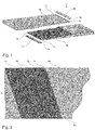
- figure 1 shows two complementary conveyor belt ends 1a, 1b prepared for connection by means of a high-strength and permanently elastic adhesive. These are arranged opposite one another in such a way that they represent a possible construction of a connection between two conveyor belt ends 1a, 1b by means of a high-strength and permanently elastic adhesive as described above.
- the ends 1a, 1b of the conveyor belt 1 to be glued can be the ends of the same conveyor belt 1 or of different conveyor belts.
- the adhesive described above is therefore suitable, for example, for connecting (rubber) conveyor belts to form an endless belt or for assembling such an endless belt 1 from a number of sections of conveyor belts that are easy to handle.
- strips 2a, 2b - here with a trapezoidal cross section - are provided, which can bridge a corresponding joint gap 3a, 3b on the outer covering layer 4a, 4b of the conveyor belt 1.
- the strips 5a of the stepped profile that form the top 5c or bottom step are therefore designed to match this strip 2a, 2b.
- a corresponding configuration the opposite outer (off) cover layer 4a, 4b of the conveyor belt 1 is provided.
- the longest strip 5a, 5b forming a step protrudes beyond the longer of the two outer covering layers 4a, 4b of the conveyor belt.
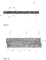
- FIG 2 shows a top view of a stepped profile of a conveyor belt end 1 prepared for connection using a high-strength and permanently elastic adhesive.
- the steps 5a, 5b, 5c do not extend parallel to the conveyor belt end 1a, but opposite it in at an angle in the range >0° and ⁇ 90°. Due to the mutually parallel sides 6a, 6b of the conveyor belt 1 and the step sides not running at an angle of 90° thereto, each step 5a, 5b, 5c forms a trapezoidal shape.
- the trapezoidal design of the steps 5a, 5b, 5c has the advantage that when the connection is subjected to a tensile load, the entire contact point between two steps 5a, 5b, 5c is not simultaneously subjected to a tensile load, which could possibly encourage the connection to tear. Rather, an edge area is initially subjected to tensile loading and only then further areas of the contact point between two steps 5a, 5b, 5c.
- the load on the connection from other components of the conveyor system e.g. transport rollers, drive means, deraille, scrapers
- steps 5a, 5b, 5c can each have the same width. However, this is not mandatory. Depending on requirements, steps 5a, 5b, 5c of different step widths could also be used. This could be advantageous, for example, if the overall length of the connection is to be as short as possible. In this case, more stressed steps 5a, 5b, 5c could be made longer than less tensile stressed ones.
- FIG 3 a side view of a possible construction of a connection between two conveyor belt ends 1a, 1b by means of a high-strength and permanently elastic adhesive 7 is shown.
- the bonding by means of an adhesive 7 as described above between the contact surfaces of the individual steps 5a, 5b, 5c can be seen.
- a band consists of two cover layers 4a, 4b and a core divided into 4 levels or layers 8a, 8b, 8c, 8d.
- the 4 planes or layers 8a, 8b, 8c, 8d and the respective strip end 1a, 1b thus form 3 steps 5a, 5b, 5c.
- a core subdivided into 4 levels 8a, 8b, 8c, 8d is formed again.
- the length of the respective connection and the number of steps 5a, 5b, 5c can be selected based on DIN 22102, for example.
- the butt gaps 3a, 3b between the two respective cover layers 4a, 4b are each bridged by a butt gap strip 2a, 2b. This can also be attached using the adhesive 7 described above.
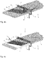
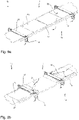
- Figure 4a shows an example of the end of the conveyor belt 1a that the contact point to be connected between the ends of the conveyor belt 1a, 1b is prepared accordingly before the bonding.
- the conveyor belt ends 1a, 1b are provided with a stepped profile before they are glued.
- the stepped profiles of the two conveyor belt ends 1a, 1b to be connected are designed in such a way that when the conveyor belt ends 1a, 1b overlap, they add up to the same thickness. Such an embodiment prevents, on the one hand, the thickness of the conveyor belt 1 from increasing in the overlapping area in an undesired manner.
- the steps 5a, 5b, 5c do not run perpendicularly to the longitudinal direction L of the conveyor belt 1, but at an angle ⁇ between, for example, 5° and 85°, preferably between 10° and 70°, in particular with respect to this direction preferably between 15° and 55°, particularly preferably between 15° and 45°.
- one of the tape ends is first fixed on a suitable base 9, such as a flat workbench. This can be done, for example, by means of screw clamps 10 and optionally by suitable pressure distribution devices 11 . Subsequently, the individual layers 8 are gradually removed to form the steps 5 described above. As related to above figure 2 has been described, but also Figure 4a is shown, the respectively removed steps 5 have a trapezoidal profile. If the individual layers 8 also include a textile layer (not shown here), this is also removed. In Figure 4a shows how the abutting edges of the individual steps 5 are produced by inserting a cut. The individual layers 8, such as the rubber cover 4 can then be removed. If necessary, a belt plane (not shown) must be used for this purpose. The other layers are removed in the same way.
- the respective other side of the belt or the other end of the conveyor belt 1a, 1b must be prepared in the same way.
- the angle ⁇ with respect to the Longitudinally L of the band 1 extends in such a way that in the event of an overlap, the steps 5 extend in parallel and are located on the opposite side, so that when the respective ends 1a, 1b overlap, the steps 5 interlock so that the steps 5 and the abutting surfaces of the two tape ends 1a, 1b each contact and in the sum result in a tape height that corresponds to the original tape height.
- the contact surfaces are cleaned, for example using a wire brush 12 as in Figure 4b shown roughened in order to improve the adhesion of the adhesive 7 and thus also of the tape ends 1a, 1b to one another. Roughening is preferably carried out transversely to the direction of transport.
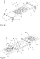
- - as in Figure 4c shown - the adhesive 7 are applied. This can be done using a cartridge gun 13, for example. Before doing so, however, it is advisable to check the alignment of the conveyor belt ends 1a, 1b to be connected and the dimensional accuracy of the connection, and to place a protective film 28 between the base or workbench 9 and the conveyor belt ends 1a, 1b to be connected, in particular to prevent them from becoming soiled with adhesive.
- the above-described adhesive 7 in contrast to contact adhesives known from the prior art, still offers the possibility of moving the individual elements relative to one another, due to the already existing adhesive force and the in many cases difficult handling of long and/or wide ones and/or heavy conveyor belts 1, it is difficult to correct the position and this should be avoided if possible.
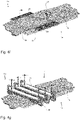
- the tape ends 1a, 1b are removed as in Figure 4e shown assembled.
- the position of the tape ends 1a, 1b relative to one another can still be corrected if necessary, as long as the adhesive 7 is not yet too firm.
- connection point For the final curing, the connection point should be clamped in a corresponding fixing device 10, 11.
- a pressurization by means of an exemplary fixing device 10, 11 is in Figure 4g shown.
- the curing time to safe (hand or handling) strength at 23°C is approx. 60 minutes. However, the time required in each case depends on the composition of the adhesive and the temperature.
- the connection should then be checked again. In the present example, the functional strength of the connection point is reached after approx. three to four hours.
- the fixing device 10, 11 can be removed and the tape can be reworked if necessary.
- the post-processing steps can include, for example, cutting off or grinding off protruding sections of tape.
- a major advantage of the adhesive 7 described above and the method for using this adhesive 7 is that the adhesive not only adheres well to rubber, but also to other materials, including those that are not elastically deformable, and adheres very well.
- the adhesive 7 is also suitable for gluing, for example, metal drums 16 with rubber coatings 17.
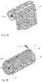
- An example of how this can be done is the Figures 5a - h shown.
- First - as in Figure 5a is shown schematically - the planned covering 17 roughened on the adhesive surfaces 18 and 19 cut edges. This can be done, for example, with a roughener 12 known from the prior art or with an angle grinder.
- the adhesive surfaces 18 should be cleaned before the adhesive 7 is applied.
- the covering When the covering is prepared as described above, first apply the adhesive 7 - as in Figure 5b shown schematically - applied to the surface of the drum 16 by means of a caulking gun 13.
- the adhesive 7, which is initially applied in strips, is then evenly distributed using a brush, spatula 14 or another suitable tool. It has proven advantageous here to use an amount of adhesive of approximately 100 to 150 g/m 2 . This amount can be applied in one coat. A second coat is usually not necessary. Care should be taken that the entire surface of the drum 16 to be coated is completely wetted.
- the adhesive 7 Since the adhesive 7 starts curing after being applied to the drum 16, it is important to record the time from application. Although a long time between application and contact with the covering 17 increases the initial adhesion between these parts 16, 17, correct alignment is made more difficult if the initial adhesion is too great. Therefore, immediately after applying the adhesive 7 to the drum 16, the adhesive 7 should also be applied to the inner surface 18 of the covering 17. As in Figure 5c is shown schematically, the adhesive 7 is applied to this surface 18 applied. Here, too, the adhesive 7 should be evenly distributed using a spatula 14, brush or similar tool. The surface 18 of the covering 17 should be wetted as completely as possible.
- the adhesive 7 Before the covering 17 comes into contact with the drum 16 to be coated, the adhesive 7 should dry for a predetermined time in order to achieve the required initial adhesion. Depending on the composition of the adhesive 7, this time interval differs. Different compositions of different adhesives 7 can be used to set different time intervals that are available for preparing the surfaces 16, 18 to be bonded. In the case of very large adhesive surfaces in particular, it makes sense to use adhesives 7 that can be processed for a longer period of time. For a given adhesive composition, the working time can be controlled by changing the temperature. An example of the relationship between the temperature and the recommended processing time is shown in figure 13 shown.
- the most favorable point in time for contacting the correspondingly prepared surfaces 16, 18 can be determined using the so-called back of the finger method. This means that when the back of the finger makes contact with the adhesive surface, the adhesive point feels dry and no threads form between the back of the finger and the surface 16, 18 to be bonded when the back of the finger is removed.
- the covering 17 is laid as in Figure 5d applied to the drum 16 as shown.
- the covering 17 is placed on the drum 16 at the cutting edge 19 .
- the drum 16 should be mounted so that it can rotate as far as possible.
- the cutting edge 19 can be laid parallel to the longitudinal axis 20 of the drum in a comparatively simple manner and the covering 17 can be gradually contacted with the drum surface by the rotation of the drum 16 .
- the covering 17 While the covering 17 is being applied, it should be pressed from the inside outwards along the longitudinal axis 20 of the drum by means of a suitable roller 15 .
- a roller 15 for applying pressure has proven to be advantageous for this purpose.
- the drum 16 continues to rotate until the lining 17 is fully seated on the drum surface. If necessary, the lining 17 could be tapped on the drum 16 with a rubber mallet. Air inclusions should be avoided and, for example, pushed out laterally by the roller 15 described above.
- the cutting edge 19c produced is ideally roughened and dust or abrasion is removed using a broom, a brush, compressed air or another suitable tool 14.
- the cutting edge 19c is then also provided with adhesive 7.
- this adhesive 7 is an adhesive 7 that differs from the previously used adhesive 7 and has a significantly shorter curing time. In this way, it can be achieved that the adhesive 7 applied to the cut edge 19c that has now been introduced hardens very quickly and can be bonded to the opposite end 19a of the rubber band in a butt joint.
- the covering 17 is preferably pressed again with a roller 15 (not shown here) along the longitudinal axis 20 of the drum 16 .
- the joint 19a, 19c can be pressed down with a corrugated roller or tapped with a rubber mallet in order to achieve better adhesion.
- the covering 17 should then be pressed onto the drum 16 until the adhesive 7 has completely hardened. This could be done, for example, by means of straps (not shown). Wrapping with a stretch film has proven to be particularly suitable. After complete curing and functional stability should be achieved - as for example in Figure 5h shown - protruding edges 21 are cut off by means of a knife, a saw, an angle grinder or another suitable tool 22. The joint between the two ends of the 19a, 19c covering 17 can be equalized if necessary. An angle grinder 22 could be used for this purpose, for example.
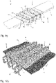
- FIG 6 shows a schematic cross-sectional view of a connection point of a conveyor belt 1 reinforced with steel cable belts 23.
- Such conveyor belts 1 are often found where heavy loads are to be transported and/or loads are to be transported over long distances. Since the tensile stresses that occur in the process often cannot be borne by rubber webs alone, reinforcements such as steel cables 23 are usually incorporated into such conveyor belts 1 .
- a textile reinforcement 24 can be provided. This, however, their handling, among other things, due to the additional Density, which makes greater rigidity more difficult. Therefore, particularly in the case of such conveyor belts 1, a connection of conveyor belt ends 1a, 1b that can be implemented quickly and easily without the use of heavy equipment—for example in the event of a tear—is desired.
- a connection point in the in figure 6 shown cross-sectional view of a connection point is a plurality of reinforcement elements 23, here steel cable belts 23 shown. These can - as below in connection with the Figures 7a - c is described - be connected to different ends 1a, 1b of the conveyor belt 1.
- one of these reinforcement elements 23 together with the surrounding material 25, in particular the surrounding rubber material forms a so-called finger 26a, which is connected to the adjacent fingers 26b, 26c (which are assigned, for example, to the other conveyor belt end 1a, 1b) by the above-described Glue 7 is glued.
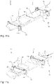
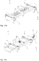
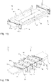
- Figures 7a - c show schematic representations of different variants of possible connections of ends 1a, 1b of a conveyor belt 1 reinforced with steel cable belts 23.
- the connection types shown differ in the overlapping of adjacent fingers 26a, 26b, 26c and in the length of individual fingers 26a, 26b, 26c.
- Figure 7a shows a 2-stage belt connection. Such is sufficiently stable and flexible for most connections.
- three different finger types 26a, 26b, 26c are glued together.
- the three different finger types 26a, 26b, 26c are a finger 26n full finger length (L S1/1 ) starting from the first conveyor belt end 1a, a finger 26o full finger length (L S1/1 ) starting from the second conveyor belt end 1b and finger 26p , 26q half finger length (L S1/2 ) starting from the first or second end of the conveyor belt. It is provided that a finger 26n full finger length starting from the first end of the conveyor belt 1a at the second end of the conveyor belt 1b is opposite a gap between two fingers 26o, 26q.
- a gap at the first end 1a of the conveyor belt lies opposite a finger 26o full finger length, starting from the second end 1b of the conveyor belt.
- Fingers 26p, 26q of half the length of a finger also lie opposite a finger 26p, 26q of half the length of a finger on the opposite end of the conveyor belt 1a, 1b.
- Combinations of fingers 26p, 26q or fingers 26n, 26o and gaps that result in a full finger length (L S1/1 ) are referred to as a finger pair 27. With each pair of fingers 27 it is thus ensured that the sum of the opposite finger lengths (L sn ) starting from the two conveyor belt ends 1a, 1b results in a full finger length (L s1/1 ).
- the arrangement of these fingers 26 or pairs of fingers 27 in the two-stage connection can, for example, be as shown in Figure 7a be shown.
- a finger 26n full finger length starting from the first conveyor belt end 1a is followed by a finger 26o full finger length starting from the second conveyor belt end 1b and this is followed by a combination of two fingers 26p, 26q half finger length starting from both conveyor belt ends 1a, 1b.
- Each sequence of these three pairs of fingers 27 is followed by an identical triple of these pairs of fingers 27 .
- each pair of fingers 27 with a finger 26n, 26o full finger length is followed by a pair of fingers 27 made up of fingers 26p, 26q half the finger length.
- each quartet of finger pairs 27 would be followed by an identical quartet of finger pairs 27 .
- each finger pair 27 consists of a combination of fingers 26 or fingers 26 and gaps that make up a full finger length (L S1/1 ).
- L S1/1 the full finger length
- the arrangement of the pairs of fingers 27 next to each other - ie in the width direction of the conveyor belt 1 - can vary depending on the requirements.
- the Figure 7b illustrated embodiment is only one possible example.
- fingers 26, full finger length can extend from both conveyor belt ends 1a, 1b (in Figure 7b only full finger length fingers are shown starting from the right end of the conveyor belt). Due to the possible variation of the contact point between fingers 26 of a pair of fingers 27 with this type of connection, it is possible to space the weak points of such a connection in the width direction of the strip 1 as far apart from one another as possible.
- the in Figure 7c illustrated single-stage belt connection.
- fingers 26 full finger length alternate in each case starting from the opposite ends 1a, 1b of the conveyor belt.
- FIGs 8a and b Schematic cross-sectional representations of ends 1a, 1b of a conveyor belt 1 reinforced with steel cable belts 23 that are to be connected or are connected are shown. While the core, which is formed by the fingers 26 encompassing the steel cables 23, in Figure 8a is already glued, this figure shows how the top layer 4a, 4b is applied. This can be done with or without a textile reinforcement 24 . So that the cover layer 4a, 4b can be inserted into the connection point with as precise a fit as possible, the ends of the connection point are bevelled, preferably running from the outside inwards. This also enables simplified handling.
- the top layer 4a, 4b in the area of the connection point can be applied to the core analogously to that in connection with Figure 4f described butt gap strips 2a, 2b are applied.
- a textile reinforcement 24 (on one or both sides) can be arranged between the core and the cover layer 4a, 4b.
- the finished connection between the conveyor belt ends 1a, 1b with the applied cover layer 4a, 4b and textile reinforcement 24 is in Figure 8b shown.
- FIG Figure 9a schematically represent an exemplary method for connecting two conveyor belt ends 1a, 1b of conveyor belts 1 reinforced with steel cable belts 23.
- FIG Figure 9a a schematic representation of a method step for preparing to be connected ends 1a, 1b of steel cord belts 23 reinforced conveyor belts.
- the belt ends 1a, 1b to be connected are first fixed and for this purpose placed, for example, on a lower fixing device or flat workbench 9 and fixed, for example, with squared timber and/or belt tensioners or other suitable tools 10, 11.
- a sufficiently large distance should be maintained in order to be able to turn both sides of the tape.
- the tape should then be shortened to form a straight butt edge.
- the abutting edge is preferably aligned at an angle of 90° to the longitudinal direction of the strip.
- other angles are also possible and (as described above with regard to non-steel cord reinforced belts) could result in a more favorable distribution of the tensile load at the joint.
- the connection length could be selected based on DIN 22131 or ISO 15236 Part 4, for example.
- the length of the connection and, if applicable, the angle (90° or deviating from this in the case of a trapezoidal connection (see above)) are determined on the tape ceiling 4 marked.
- the tape cover 4 is then carefully cut with a suitable tool, for example a knife or cutter 22 . It should be noted here that the core containing the steel cables 23 is not cut if possible in order to maintain the strongest possible connection between the fingers 26 (not shown) and the remaining belt end 1a, 1b.
- Figure 9b shows a schematic representation of a further process step for preparing ends 1a, 1b to be connected of conveyor belts 1 reinforced with steel cord belts 23.
- the belt edges 6a, 6b (arranged laterally with respect to the longitudinal direction of the belt) have been cut off in the area of the connection. This is not mandatory. However, since these areas usually do not contain any reinforcement belts 23, these are not necessary for the (re)construction of the core in the area of the connection and could interfere with subsequent method steps. Therefore, removal is recommended.
- the cover layers 4c, 4d are then pulled off the marked tape ends 1a, 1b.
- Figure 9c shows a schematic representation of a method step for forming connectable fingers 26 on ends 1a, 1b to be connected of conveyor belts 1 reinforced with steel cable belts 23.
- the exposed cores of both conveyor belt ends 1a, 1b are severed in the longitudinal direction L of the conveyor belt 1.
- Cutting is preferably done using a knife, a saw, a cutter or another suitable tool 22.
- cuts perpendicular to the conveyor belt surface not only are particularly easy to implement, but also one allow particularly permanent bonding of the fingers 26.
- Hexagonal or octagonal cross-sections of fingers 26 have been found to be less preferred. All of the longitudinal sections preferably have the same spacing from each adjacent longitudinal section.
- individual fingers 26x (2n-1) , 26y (2n) are removed or shortened to form finger pairs 27 each having the full length of a finger 26. If, as described above, all longitudinal cuts were made at the same distance from each adjacent longitudinal cut, all fingers 26 have the same width, so that they can interlock particularly well and lie tightly against one another.
- the fingers 26 that are now formed are folded back onto the remaining part of the respective conveyor belt 1 and that the lower cover layer 4b is positioned at the point of connection.
- a protective layer 28 for example a glass fiber reinforced PTFE film or silicone film, on the fixing device, on which the cover layer is then positioned.
- the protective layer is preferably slightly longer and wider than the planned connection. An overlap on at least two opposite sides, preferably on all four sides, of about 10-30 cm, preferably about 20 cm, has proven to be preferred.
- the protective layer 28 is larger than the planned connection point, the lower cover layer 4b can still be moved on this protective layer and positioned exactly in such a way that the fingers 26 or finger pairs 27 can later be arranged and glued on it.
- the protective layer 28 serves in particular to prevent the adhesive 7 from adhering to the fixing device 10 , 11 .
- the cover layer 4b which preferably has overhangs for overlapping with the remaining conveyor belt sections, is now placed on the protective layer 28 and aligned in such a way that the fingers 26 can be arranged and glued on it.
- a textile reinforcement 24 is placed on the side of the cover layer 4b that faces away from the protective layer 28 (that is to say later faces the fingers). If a textile reinforcement 24 is provided, this is preferably so elastic that the conveyor belt 1 is not additionally stiffened as a result, so that the belt 1 can be deflected around tight radii and the minimum drum diameter can thus be maintained.
- the adhesive 7 is applied to all contact surfaces as quickly as possible and then distributed evenly using a suitable tool, for example a spatula or brush 14 .
- a brush 14 is particularly useful since the adhesive 7 should also be rubbed into pores.
- Adhesive 7 must also be applied to the side surfaces of fingers 26 in order to be able to ensure a permanent connection between adjacent fingers 26 . As mentioned above, the adhesive 7 should be applied as quickly as possible.
- Adhesion to the exposed surfaces can be guaranteed.
- the amount of glue required depends in particular on the size of the gaps between adjacent fingers 26 . However, at least a quantity of 1,000 g/m 2 should be used.
- the time must be recorded. Due to the complexity of the finger connection described, a large part of the time during which the adhesive 7 can be processed usually elapses with the application and distribution of the adhesive 7. Longer processing times would indeed increase the initial adhesion, but the maximum processing time must not be exceeded.
- Figure 9e shows schematically a method step for gluing fingers 26 of ends 1a, 1b to be connected to one another of conveyor belts 1 reinforced with steel cord belts 23.
- the fingers 26 of both belt sides 1a, 1b are preferably starting with the inner ones (i.e. those furthest away from the belt broad sides) Fingers folded back so that they come to rest on the prepared top layer 4b.
- fingers 26 with a rectangular cross section they can be glued directly to one another. Fingers 26 with hex cuts or gaps between adjacent fingers require filling material to be placed between the fingers and significantly more adhesive used.
- Glue 7 is shown applied to the interconnected fingers 26 of conveyor belts 1 reinforced with steel cable belts 23 in order to apply a second cover layer 4a to the side of the interconnected fingers 26 opposite the first cover layer 4b.
- the adhesive 7 preferably with an amount in the range of 200 - 2000 g/m 2 , preferably in the range of 300 - 1000 g/m 2 depending on the weaving density of the textile fabric and the distance between adjacent fingers 26
- a cartridge pistol 13 is preferably applied with a cartridge pistol 13 on the surface and in all gaps or introduced.
- a suitable tool 14 for example a brush or spatula, and preferably also rubbed into pores (for example with a short-bristled brush).
- the glue 7 should be applied with a slight excess between the fingers and in the gaps and evenly distributed.
- the surface of the second cover layer 4a to be connected with the fingers should also be applied with the adhesive 7, preferably also using a cartridge gun 13. Overlapping areas provided for connection to the existing cover layer 4c, 4d of the conveyor belt sections adjacent to the connection point should also be treated with adhesive 7 are applied.
- the adhesive 7 is preferably distributed evenly over the surface to be acted upon using a suitable tool 14, preferably a spatula or brush, and is also rubbed into pores (preferably using a short-bristled brush).
- the cover layer 4a, 4b is preferably treated with an amount of adhesive in the range of about 100-800 g/m 2 , preferably 150-600 g/m 2 , particularly preferably 200-400 g/m 2 .
- the amount of adhesive required depends in particular on the roughness of the surfaces to be bonded and the weaving density of the textile fabric 24 .
- the adhesive 7 is also applied to the outer areas of the first cover layer 4b. This is necessary in order to be able to fix the outer edges of the conveyor belt 1 or—if these were previously removed—new outer edges of the conveyor belt 1 .
- the second cover sheet 4a can be placed on the glued finger joint.
- the top layer 4a should be pressed down lightly.
- a roller 15 for pressing has proven to be particularly preferred, since it can be used to expel air pockets to the outside and at the same time a high contact pressure can be achieved.
- connection point can also be protected laterally.
- a space remaining between the folded ends of the protective layer 28 can be covered by laying on a further protective layer.
- the folded protective layer allows in particular Protection of the lateral edges and thus the application of edge rails 29 during fixation. This allows the (in Figure 9g no longer recognizable) fingers 26 are pressurized in the width direction of the conveyor belt 1.
- the edge rails 29 should have a slightly lower height than the conveyor belt 1 in order not to impair the pressurization of the connection point.
- a height difference of 0.5 - 1.5 mm, preferably about 0.8 - 1.2 mm, particularly preferably 0.9 - 1.1 mm has proven to be particularly suitable, since this also means that pressure can be applied over a large area in the height direction of the conveyor belt is possible.
- Figure 9g 1 is a schematic representation of a transport belt 1 reinforced with steel cable belts 23 in order to set the adhesive 7 in place.
- the edge rails 29 are subjected to pressure in the direction towards one another by suitable means 35 (here length-adjustable steel cables, but chains with turnbuckles would also be conceivable, for example). This also ensures that the fingers 26 are subjected to pressure towards one another or in the direction of the width of the conveyor belt 1 .
- suitable means 35 here length-adjustable steel cables, but chains with turnbuckles would also be conceivable, for example.
- This also ensures that the fingers 26 are subjected to pressure towards one another or in the direction of the width of the conveyor belt 1 .
- sufficient pressure is applied to the adhesive points in the width direction of the conveyor belt.
- connection point is also pressurized in the vertical direction.
- an upper pressure distribution device 11 here a (possibly prestressed) plate
- suitable pressure application means 10 here, for example, screw clamps
- the fixing device should therefore not only fix the tape and the connection point for the duration of the curing of the adhesive 7, but also exert sufficient pressure on the connection point.
- a pressure in the range of 10-50 N/cm 2 preferably in the range of 15-30 N/cm 2 , particularly preferably of about 20 N/cm 2 , has proven to be suitable for steel cable belts. This pressure ensures that sufficient adhesive 7 is also pressed between the fingers 26 and possibly into the textile fabric 24 .
- a vulcanizing press could also be used if available, which could also accelerate curing with appropriate temperature control.
- U-profiles 10a are used for uniform pressurization, with the pressure being able to be adjusted locally by adjusting screws 30 and/or the deflection of the profiles 10a being compensated if necessary.
- the U-profiles 10 are arranged on opposite sides of the adhesive connection, preferably pressurize another pressure distribution device 10b there and are pressurized towards one another by screw clamps 11 or other suitable tools 11 .
- Figure 10b shows an alternative in which pre-bent hollow profiles 10a are used in order to apply pressure evenly over a large area to further pressure distribution devices 10b - for example composite material panels.
- the pre-bent hollow profiles are arranged on opposite sides of the adhesive connection and are pressurized towards one another by means of screw clamps 11 or other suitable tools 11 .
- Figure 11a-k show a schematic representation of a further alternative for connecting ends 1a, 1b with steel cable belts 23 reinforced conveyor belts 1.
- This alternative is significantly simpler than the variant described above according to FIG Figures 9a - g.
- the formation of separate fingers is not necessary, but after the formation of a common abutting edge 31 on the conveyor belt ends 1a, 1b to be connected, notches 32 running parallel to the steel cables 23 are merely produced in the additional tensile load transmission means 33 such as Steel cables are inserted in such a way that they bridge the abutting edge 31 of the conveyor belt ends 1a, 1b to be connected.
- the overlapping area of the previously included steel cables 23 and the newly inserted tensile load transfer means 33 should be chosen so that the connection point has a length analogous to DIN 22131 or ISO 15236 Part 4.
- Figure 11a shows a schematic representation of a method step for preparing ends 1a, 1b to be connected of conveyor belts reinforced with steel cable belts 23.
- the belt ends 1a, 1b to be connected are first fixed and for this purpose placed, for example, on a lower fixing device or flat workbench 9 and fixed, for example, with squared timber and/or belt tensioners or other suitable tools 10, 11.
- a sufficiently large distance should be maintained in order to be able to turn over both tape ends 1a, 1b.
- the band 1 should then be shortened to form a straight butt edge 31 .
- the abutting edge 31 is preferably aligned at an angle of 90° to the longitudinal direction of the strip.
- connection length is now marked.
- the connection length could be selected based on DIN 22131 or ISO 15236 Part 4, for example.
- the length of the connection and, if necessary, the angle (90° or deviating from this in the case of a trapezoidal connection (see above)) are marked on the tape cover 4.
- the tape cover 4 is then carefully cut with a suitable tool, for example a knife or cutter 22 . It should be noted here that the core containing the steel cables 23 is not cut if possible in order to maintain the strongest possible connection with the remaining belt ends 1a, 1b.
- Figure 11b shows a schematic representation of a further method step for preparing ends 1a, 1b to be connected of conveyor belts 1 reinforced with steel cord belts 23.
- the belt edges 6a , 6b are separated in the area of the connection.
- the cover layers 4c, 4d are pulled off the marked tape ends 1a, 1b.
- Figure 11d shows a schematic representation of a method step for forming a plurality of indentations or furrows 32 which are arranged between the webs 34 each surrounding a steel cable 23 .
- the grooves 32 thus extend in the longitudinal direction of the Conveyor belt 1.
- a knife and/or an electric (or in a critical environment—for example underground—a pneumatic) belt plane 22 is recommended for this purpose.
- the belt ends 1a, 1b are aligned with one another in such a way that the abutting edges 31 of both belt ends 1a, 1b lie against one another. Then the tape ends 1a, 1b as in Figure 11e shown turned over, so that the abutting edges rest on a section of the conveyor belt 1 associated with the belt end 1a, 1b. The strip ends 1a, 1b are fixed in this position and the butt gap strip 2 is placed on the fixing device. If desired, a textile reinforcement (not shown here) is applied to the butt gap strip 2 .
- the adhesive 7 is applied to all contact surfaces as quickly as possible and then distributed evenly using a suitable tool, for example a spatula or brush 14 .
- a brush 14 is particularly useful since the adhesive 7 should also be rubbed into pores.
- the adhesive 7 should be applied as quickly as possible, since the surface to be acted upon by the adhesive 7 is very large and the adhesive 7 in the static mixer 13 begins to harden after a very short time.
- the belt ends 1a, 1b are folded back so that the joint gap 3 formed on one side between the two belt ends 1a, 1b as in Figure 11g shown comes to rest on the butt gap strip 2 and is glued to it.
- the tape ends 1a, 1b can be pressed onto the butt gap strip 2, for example by means of a roller (not shown here).
- Adhesive 7 is then introduced into the indentations or furrows 32 and onto the surfaces of the webs 34, for example by means of a caulking gun 13.
- the adhesive can be distributed using suitable tools 14 such as a brush or spatula.
- the tensile load transmission means 33 such as steel cables inserted in such a way that one is preferably arranged in each furrow 32 and can be glued to the furrow walls in this. If necessary, adhesive 7 squeezed out can be distributed with a suitable tool 14 . If a tensile load transfer means 33 is arranged in each groove 32, it should be ensured that the surfaces of the webs 34 are also applied to the surface with adhesive 7, because now, as in Figure 11i shown, the cover layer 4a are applied thereto. For this purpose, the underside has already been applied with adhesive 7 over its entire surface.
- the cover layer 4a After the cover layer 4a has been placed on the grooves 32, tensile load transfer means 33 and webs 34 provided with adhesive and has preferably been pressed lightly, the lateral overhang of the protective layer 28 is wrapped around the connection point. As a result, the connection point can also be protected laterally. It may be advantageous to lay a further protective layer between the folded ends of the protective layer 28 in order to cover an intermediate space remaining between the folded ends of the protective layer 28 .
- Edge rails 29 are preferably applied as shown in order to also fix the connection point in the width direction. Since - unlike the finger connection - the individual furrows and webs remain constantly connected to each other, this fixation is less critical and mostly optional. As described above, the edge rails 29 should have a slightly lower height than the conveyor belt 1 in order to enable the large-area pressure application in the height direction of the conveyor belt. The edge rails 29 should be attached using suitable (in Figure 11k shown) means 35 are pressurized towards each other.
- Figure 11k 1 is a schematic representation of a transport belt 1 reinforced with steel cable belts 23 in order to set the adhesive 7 in place.
- the edge rails 29 are subjected to pressure in the direction towards one another by suitable means 35 (here length-adjustable steel cables, but chains with turnbuckles would also be conceivable, for example). This avoids excessive expansion of the joint in the width direction when pressurized in the height direction.
- connection point is provided by means of an upper pressure distribution device 10 (here a (possibly prestressed) plate), which is pressurized by suitable pressure application means 11 (here, for example, screw clamps) in the height direction of the conveyor belt 1 in relation to a lower pressure distribution device, namely the above-mentioned part of the fixing device .
- suitable pressure application means 11 here, for example, screw clamps
- pressure is transmitted between the pressure application means 11 and the pressure distribution device 10 U profiles used.
- the U-profiles can have bores with adjusting screws 30 arranged therein, which make it possible to adjust the pressure locally and/or to compensate for the deflection of the U-profiles.
- the adhesive consumption is usually slightly lower than in the previously described variant according to the Figures 9a - 9g .
- the adhesive requirement is usually in the range of 500-1500 g/m 2 , mostly in the range of 750-1000 g/m 2 .
- the adhesive requirement is influenced by the nature of the material (in particular roughness, tightness of the cover fabric, gap width between the groove and the means of transmission of tensile load or steel cable).
- cover layers with a textile reinforcement 24 it has proven to be preferable to use cover layers with a textile reinforcement 24 and to glue them together. This has proven to be advantageous in terms of increased connection strength with essentially the same process complexity. For a given bond strength, a shorter bond length can be used.
- Another advantage of the adhesive described above is that it can also be used to repair damaged areas in permanently elastic plastic surfaces.
- the figures show an example of how such a repair of a damaged area can take place 12a - 12f shown.
- Figure 12a shows a top view of a damaged area 36 of a conveyor belt 1 during the beveling of the damaged area edges in preparation for their repair.
- Defects 36 in a conveyor belt 1 occur comparatively frequently. The cause can be, for example, edgy transport goods that fall onto the conveyor belt 1 and damage it with an edge.
- Figure 12a comparatively small damage is shown. Such damage often extends in the longitudinal direction of the conveyor belt 1, since an object penetrating the conveyor belt 1 can get caught in other components of the transport system and be held there. If the conveyor belt 1 is then operated further, such an object literally cuts open the conveyor belt 1 in the longitudinal direction.
- the conveyor belt 1 depending on the transport speed, the degree of loading, the weight of the transported goods, the reaction time until the damage is detected and other factors - can already continue to run for several meters, often even a few hundred meters. Accordingly, cracks with an extent of up to 500 meters in the longitudinal direction of the strip can develop. If such a damaged area 36 had to be replaced, this would involve enormous effort and costs. Especially when used in an area that is difficult to access, the effort is enormous and the result is a loss of use for several days.
- the subsequent contact surfaces with the adhesive first prepare. To do this, the contact surface is enlarged by beveling the edges of the damaged area. It has proven to be preferable to bevel the edges of the damaged area at an angle of more than 30°. For example, this could be as in Figure 12a shown using a suitable tool 22, such as an angle grinder or a knife.
- the surface should be as for example in Figure 12b shown be abraded in order to achieve improved adhesion of the adhesive 7.
- a suitable tool 12 such as a grinding wheel (eg K16)
- it should be operated at a low speed, for example 800 rpm or less. Due to the preferred low number of revolutions, damage to the permanently elastic plastic, for example burning of the rubber, can be avoided or at least reduced.
- the edges of the damaged area 36 should then be roughened, which can further improve the adhesion of the adhesive. This could be done, for example, using a round metal brush or a roughening brush. Roughening should be done across the transport direction to achieve the best possible adhesion.
- Abrasion and other dirt must then be removed, for example using a brush, compressed air or other suitable means 14.
- the contact surfaces should be dried with absorbent paper and slightly heated.
- a hot air application device has proven to be suitable. Heating above 60°C should be avoided in order not to damage the conveyor belt and to ensure that the adhesive 7 can be processed.
- a textile reinforcement 24 should be inserted in the case of large areas of damage 36 . Especially with holes and cracks it should be wider than 1 cm or longer than 10 cm a textile reinforcement 24 can be inserted. To do this, it is advantageous to uncover a few cm of the carcass around the damaged area 36 and then to glue in the textile reinforcement 24 in order to achieve sufficient strength.
- Figure 12d shows a view of a damaged area of a conveyor belt 1 during the introduction of the adhesive 7 into the damaged area.
- the adhesive 7 can now be introduced into the damaged area 36 prepared as described above.
- the use of a caulking gun 13 has proven to be preferred.
- the first drops of adhesive 7 squeezed out with the cartridge gun 13 should be discarded, since these first drops may not contain sufficiently mixed components.
- the adhesive 7 should be applied within a few minutes and then immediately rubbed into the pores 14, preferably with a short-bristled brush, in order to achieve good adhesion. Additional adhesive 7 should be applied, for example using a spatula 14 (see Figure 12e ) can be smoothed.
- the adhesive 7 is then cured. This can be done at ambient conditions or at elevated temperature. The time it takes for the adhesive 7 to harden completely depends on the temperature and is approximately 60 minutes at 23° C. for an exemplary adhesive composition. With a suitable hot air application device, curing could be reduced to less than 30 minutes, although it should be noted that at temperatures >80°C damage to tape 1 or adhesive 7 can occur.
- the repaired area can be reworked.
- 12f shows a top view of a repaired damaged area 36 of a conveyor belt 1 during mechanical post-processing.
- the repaired damaged area 36 can be ground down using a suitable tool 22 . Tape 1 can then be used again. Smaller damaged areas 36 in particular can thus be repaired within less than an hour.
- connection between the curing to the full functional strength of the tape connection and the temperature is in figure 13 shown. As can be seen from the diagram, this time depends on the adhesive used and the temperature.
- the diagram shown shows the connection between two different adhesives, namely "adhesive 20" and "adhesive 40". Shown are exemplary connections from one with steel cable belts Conveyor belt reinforced with 20 mm thickness. For ambient conditions of 23C°, for example, a curing time of at least 8 hours is recommended for "Glue 20". With “Glue 40" the curing time should be at least 18 hours.
- the curing time can be adapted to the respective requirements with the appropriate temperature control.
- an appropriate heating source e.g., a heat mat, IR lamp, hot plate, curing press, or other
- a curing time of less than 2 hours could be achieved, which is compared to the previously used to connect conveyor belt ends
- Procedure means a significant reduction and thus cost savings and loss reduction through reduced downtime.
Landscapes
- Engineering & Computer Science (AREA)
- Mechanical Engineering (AREA)
- Chemical & Material Sciences (AREA)
- Organic Chemistry (AREA)
- Chemical Kinetics & Catalysis (AREA)
- General Chemical & Material Sciences (AREA)
- Medicinal Chemistry (AREA)
- Health & Medical Sciences (AREA)
- Manufacturing & Machinery (AREA)
- Polymers & Plastics (AREA)
- Physics & Mathematics (AREA)
- General Engineering & Computer Science (AREA)
- Fluid Mechanics (AREA)
- Thermal Sciences (AREA)
- Adhesives Or Adhesive Processes (AREA)
- Lining Or Joining Of Plastics Or The Like (AREA)
Claims (14)
- Procédé pour le collage à haute résistance et à élasticité permanente d'au moins deux surfaces l'une avec l'autre, dont au moins une surface est une surface d'une matière plastique à élasticité permanente, au moyen d'un adhésif (7) comportant un composant polyuréthane, comportant les étapes consistant à :a) appliquer l'adhésif (7) sur au moins une première des surfaces à assembler ;b) assurer des conditions dans lesquelles au moins un premier mécanisme de durcissement de l'adhésif (7) a lieu, lequel comporte au moins une réaction chimique avec la formation d'une liaison chimique comprenant au moins un atome de soufre ;c) mettre en contact la première surface pourvue de l'adhésif (7) avec la deuxième surface, facultativement également pourvue de l'adhésif (7) ;d) assurer des conditions dans lesquelles au moins un deuxième mécanisme de durcissement de l'adhésif (7) a lieu, lequel comporte au moins la formation de structures cristallines à partir de polymères amorphes.
- Procédé selon la revendication 1,
caractérisé par le fait que
l'on utilise un adhésif (7) avec moins de 5 % en poids de solvant, de préférence moins de 3 % en poids de solvant, de façon davantage préférée moins de 1 % en poids de solvant, et, de façon particulièrement préférée, on utilise un adhésif (7) sans solvant, de telle sorte qu'un intervalle de temps minimum entre les étapes b) et c) nécessaire pour l'évaporation du solvant à une température ambiante entre 20 et 25°C s'élève à moins de 3 heures, de préférence à moins de 2 heures, de façon davantage préférée à moins d'1 heure, de façon davantage préférée à moins de 45 minutes et, de façon particulièrement préférée, à moins de 30 minutes. - Procédé selon l'une des revendications 1 ou 2,
caractérisé par le fait que
l'adhésif (7) est un adhésif à 2 composants, lequel est, de préférence, fourni dans une cartouche double (13) et est, de façon davantage préférée, appliqué sur la surface à coller au moyen d'un pistolet à cartouches (13) compatible à cet effet. - Procédé selon l'une des revendications précédentes,
caractérisé par le fait que
l'adhésif (7) est appliqué sur la surface à coller dans une quantité ≤ 500 g/m2, de préférence dans la plage de ≤ 300 g/m2, de façon davantage préférée dans la plage de ≤ 200 g/m2, de façon particulièrement préférée ≤ 100 g/m2. - Procédé selon l'une des revendications précédentes,
caractérisé par le fait qu'
au moins la surface comportant une matière plastique à élasticité permanente, de préférence du caoutchouc, de préférence les deux surfaces à coller, sont nettoyées et rendues rugueuses avant l'étape a), de préférence à l'aide d'un outil (22) choisi dans un groupe qui comporte les outils de ponçage, les meuleuses d'angle, les rabots (à bande), les brosses, les bandes abrasives, les disques abrasifs, les fraises et autres. - Procédé selon l'une des revendications précédentes,
caractérisé par le fait que
les surfaces à coller sont fixées et/ou pressées en regard l'une de l'autre après l'étape d) au moyen d'un dispositif de fixation approprié (10, 11), de préférence d'un dispositif de pressage (11), le dispositif de pressage (11) comportant de préférence au moins un élément de pressage, de façon particulièrement préférée au moins une vis de serrage, et des éléments de répartition de pression (10), les éléments de répartition de pression répartissant la pression générée par ledit au moins un élément de pression sur une surface qui comporte la zone de collage. - Procédé selon l'une des revendications précédentes,
caractérisé par le fait que
les surfaces à coller sont des parties d'une bande de matière plastique à élasticité permanente (1), de préférence d'une bande transporteuse (1), de façon particulièrement préférée d'une bande en caoutchouc, les surfaces à coller étant, de préférence, des extrémités opposées (1a, 1b) de la bande de matière plastique à élasticité permanente (1), lesquelles sont assemblées en une bande sans fin ou sont disposées sur des côtés opposés d'un emplacement endommagé (36), en particulier d'un trou ou d'une fissure, d'une bande sans fin (1). - Adhésif (7) durcissable à haute résistance et à élasticité permanente, lequel est prévu et agencé pour coller au moins deux surfaces l'une à l'autre, dont au moins une surface est une surface d'une matière plastique à élasticité permanente, de façon particulièrement préférée selon un procédé conforme à l'une des revendications précédentes,
l'adhésif (7) étant un adhésif (7) durcissant dans au moins deux mécanismes de durcissement différents, le premier mécanisme de durcissement comportant au moins une réaction chimique avec la formation d'une liaison chimique comprenant au moins un atome de soufre, et le deuxième mécanisme de durcissement comportant au moins la formation de structures cristallines à partir de polymères amorphes, caractérisé par le fait que
l'adhésif (7) comporte un composant polyuréthane. - Adhésif (7) durcissable à haute résistance et à élasticité permanente selon la revendication 8,
caractérisé par le fait que
l'adhésif (7) comporte moins de 5 % en poids de solvant, de préférence moins de 3 % en poids de solvant, de façon davantage préférée moins de 1 % en poids de solvant, et est, de façon particulièrement préférée, exempt de solvant. - Adhésif (7) durcissable à haute résistance et à élasticité permanente selon l'une des revendications 8 ou 9,
caractérisé par le fait que
l'adhésif (7) est ajusté par le choix et le rapport en poids du composant donnant du soufre et du composant polyuréthane de telle sorte que lesdits au moins deux mécanismes de durcissement différents sont aptes à être initiés à une température ambiante dans la plage de -50 à +80°C, de préférence de -30 à +70°C, de façon davantage préférée de -10 à +65°C, de façon particulièrement préférée de 0 à +60°C. - Adhésif (7) durcissable à haute résistance et à élasticité permanente selon l'une des revendications 8 à 10,
caractérisé par le fait que
l'adhésif (7) présente, à l'état durci, une résistance à la déchirure > 6 N/mm2, de préférence > 8 N/mm2, de préférence > 10 N/mm2, de façon davantage préférée > 12 N/mm2, de façon particulièrement préférée > 15 N/mm2. - Adhésif (7) durcissable à haute résistance et à élasticité permanente selon l'une des revendications 8 à 11,
caractérisé par le fait que
l'adhésif (7) présente, à l'état durci, un module d'élasticité dans la plage de 0,2 - 40 N/mm2, de préférence de 0,3 - 30 N/mm2 et, de façon particulièrement préférée, de 0,4 - 20 N/mm2. - Adhésif (7) durcissable à haute résistance et à élasticité permanente selon l'une des revendications 8 à 12,
caractérisé par le fait que
l'adhésif (7) présente, à l'état durci sur du caoutchouc SBR, une résistance au pelage > 4 N/mm, de préférence > 6 N/mm, de préférence > 8 N/mm, de façon davantage préférée > 10 N/mm, de façon particulièrement préférée > 12 N/mm. - Adhésif (7) durcissable à haute résistance et à élasticité permanente selon l'une des revendications 8 à 13,
caractérisé par le fait que
l'adhésif (7) présente, à l'état durci, une dureté Shore A dans la plage de 50 - 99 Shore, de préférence 55 - 95 Shore, de façon particulièrement préférée 60 - 90 Shore.
Applications Claiming Priority (2)
| Application Number | Priority Date | Filing Date | Title |
|---|---|---|---|
| DE102017007248 | 2017-08-03 | ||
| PCT/EP2018/071100 WO2019025578A2 (fr) | 2017-08-03 | 2018-08-03 | Procédé pour le collage de gomme et adhésif pour le collage de gomme |
Publications (2)
| Publication Number | Publication Date |
|---|---|
| EP3661747A2 EP3661747A2 (fr) | 2020-06-10 |
| EP3661747B1 true EP3661747B1 (fr) | 2022-05-11 |
Family
ID=65020111
Family Applications (1)
| Application Number | Title | Priority Date | Filing Date |
|---|---|---|---|
| EP18758548.4A Active EP3661747B1 (fr) | 2017-08-03 | 2018-08-03 | Procédé pour le collage de gomme et adhésif pour le collage de gomme |
Country Status (5)
| Country | Link |
|---|---|
| US (2) | US20200180232A1 (fr) |
| EP (1) | EP3661747B1 (fr) |
| DE (1) | DE102018118869A1 (fr) |
| PL (1) | PL3661747T3 (fr) |
| WO (1) | WO2019025578A2 (fr) |
Families Citing this family (6)
| Publication number | Priority date | Publication date | Assignee | Title |
|---|---|---|---|---|
| PL3667118T3 (pl) * | 2018-12-14 | 2021-07-12 | Arnold Jäger Holding GmbH | Pas jako cięgno bez końca oraz sposób wytwarzania takiego pasa |
| US11512481B1 (en) * | 2019-02-22 | 2022-11-29 | Base King, Llc | Portable apparatus for application of sheet adhesive to flooring |
| CN111234161A (zh) * | 2020-03-09 | 2020-06-05 | 江苏东邦科技有限公司 | 砂磨用耐磨聚氨酯底胶二液型接着剂的制备方法 |
| WO2022272223A1 (fr) * | 2021-06-25 | 2022-12-29 | Saint-Gobain Performance Plastics Corporation | Joints adhésifs sans soudure et courroies mécaniques comprenant des joints adhésifs sans soudure |
| JP2025509476A (ja) * | 2022-03-23 | 2025-04-11 | キャンペン マシナリー エー/エス | 三次元製品を製造する方法及び三次元製品の製造に有用なブランク |
| EP4602910A1 (fr) * | 2024-02-14 | 2025-08-20 | Arnold Jäger Holding GmbH | Procédé de fabrication d'une courroie sans fin et machine de liaison |
Family Cites Families (9)
| Publication number | Priority date | Publication date | Assignee | Title |
|---|---|---|---|---|
| DE2320804A1 (de) * | 1973-04-25 | 1974-11-14 | Bayer Ag | Heissklebemittel |
| US4082592A (en) * | 1976-01-15 | 1978-04-04 | Bandag Incorporated | Splicing of tread strips |
| US4034617A (en) * | 1976-01-23 | 1977-07-12 | American Biltrite Inc. | Stepped belting splice |
| IL72538A (en) * | 1984-07-30 | 1990-08-31 | Volta Power Belting Ltd | Method for splicing of elastomeric belts |
| US5082147A (en) * | 1988-02-29 | 1992-01-21 | Richard Jacobs | Composition dispensing system |
| DE19733643A1 (de) * | 1997-08-04 | 1999-02-11 | Henkel Kgaa | Lösbare Klebstoffe |
| DE10200277A1 (de) * | 2002-01-07 | 2002-08-01 | Heinz Koszlat | Reparatur-Spachtelkitt-Set spez. für Schuhe |
| EP2892722A1 (fr) * | 2012-09-06 | 2015-07-15 | ExxonMobil Chemical Patents Inc. | Construction comprenant une couche de liaison |
| DE102012023181A1 (de) * | 2012-11-28 | 2014-05-28 | Basf Se | Verfahren zur Herstellung von zumindest zweilagigen Schaumstoffplatten durch strukturiertes Verkleben |
-
2018
- 2018-08-03 PL PL18758548.4T patent/PL3661747T3/pl unknown
- 2018-08-03 DE DE102018118869.2A patent/DE102018118869A1/de not_active Ceased
- 2018-08-03 US US16/636,118 patent/US20200180232A1/en not_active Abandoned
- 2018-08-03 EP EP18758548.4A patent/EP3661747B1/fr active Active
- 2018-08-03 WO PCT/EP2018/071100 patent/WO2019025578A2/fr not_active Ceased
-
2023
- 2023-05-23 US US18/201,033 patent/US20230405941A1/en active Pending
Also Published As
| Publication number | Publication date |
|---|---|
| WO2019025578A3 (fr) | 2019-05-16 |
| PL3661747T3 (pl) | 2022-10-24 |
| EP3661747A2 (fr) | 2020-06-10 |
| US20230405941A1 (en) | 2023-12-21 |
| US20200180232A1 (en) | 2020-06-11 |
| DE102018118869A1 (de) | 2019-02-07 |
| WO2019025578A2 (fr) | 2019-02-07 |
Similar Documents
| Publication | Publication Date | Title |
|---|---|---|
| DE102018118869A1 (de) | Verfahren zum Verkleben von Gummi und Klebstoff zum Verkleben von Gummi | |
| DE2930186C2 (de) | Förderbandtreibwalze | |
| EP2345321A2 (fr) | Bande de transport de machines agricoles, notamment pour andaineurs | |
| EP3216944B1 (fr) | Agencement de renforcement de structures porteuses | |
| DE102009025911B4 (de) | Fördergurt mit längs verlaufendem Randleistenprofil | |
| DE69717337T2 (de) | Verfahren zur Verstärkung von Konstruktionen durch angeklebte Kohlenstofffasern | |
| DE2810752A1 (de) | Bodenbelag sowie verfahren und vorrichtung zum herstellen desselben | |
| EP0372510B1 (fr) | Dispositif de plaques de caoutchouc pour assembler des courroies à câbles d'acier ou pour réparer une courroie à câbles d'acier | |
| WO2010054491A1 (fr) | Poutre de bois lamellé ou abouté en biais précontrainte | |
| WO2016123645A1 (fr) | Bande sans fin pourvue d'un corps de bande en métal | |
| EP3320225B1 (fr) | Courroie ou segment de courroie | |
| DE102016101502A1 (de) | Verfahren zum Ausbessern von Furniertafeln | |
| EP3526497B1 (fr) | Procédé pour produire un matériau en bande continue destiné à la réalisation de joints d'étanchéité et bande continue | |
| WO2017102116A1 (fr) | Sangle ou segment de sangle | |
| EP3269877B1 (fr) | Palier intermédiaire de rail | |
| DE102004019306A1 (de) | Oberfläche einer Behandlungseinrichtung und Verfahren zur Herstellung einer solchen Behandlungseinrichtung | |
| EP3753869A1 (fr) | Bande transporteuse, utilisation, procédé et dispositif d'empilage ou transport de découpe carton | |
| DE102007029574A1 (de) | Leder-Reparaturverfahren und Leder-Stanzvorrichtung | |
| EP3177853B1 (fr) | Rouleau à double effet | |
| DE102022125543A1 (de) | Kantenverarbeitungsverfahren | |
| EP3882012A2 (fr) | Dispositif de fabrication de sacs ou des sacs et procede de fabrication de sacs ou de sacs | |
| DE19828325C2 (de) | Verschleißschutz für eine verschleißbeanspruchte Maschinenoberfläche, insbesondere für den Boden eines Betonmischers | |
| DE102020132654A1 (de) | Befestigungselement umfassend ein Schaftelement zur Aufnahme eines Klebstoffvorrats, zum Aufkleben auf ein Substrat | |
| DE102006040800B4 (de) | Verfahren zum Verbinden einer Grundplatte mit einem Stegteil sowie Verbindung einer Grundplatte mit einem Stegteil | |
| WO2009015823A1 (fr) | Dispositif de presse |
Legal Events
| Date | Code | Title | Description |
|---|---|---|---|
| STAA | Information on the status of an ep patent application or granted ep patent |
Free format text: STATUS: UNKNOWN |
|
| STAA | Information on the status of an ep patent application or granted ep patent |
Free format text: STATUS: THE INTERNATIONAL PUBLICATION HAS BEEN MADE |
|
| PUAI | Public reference made under article 153(3) epc to a published international application that has entered the european phase |
Free format text: ORIGINAL CODE: 0009012 |
|
| STAA | Information on the status of an ep patent application or granted ep patent |
Free format text: STATUS: REQUEST FOR EXAMINATION WAS MADE |
|
| 17P | Request for examination filed |
Effective date: 20200229 |
|
| AK | Designated contracting states |
Kind code of ref document: A2 Designated state(s): AL AT BE BG CH CY CZ DE DK EE ES FI FR GB GR HR HU IE IS IT LI LT LU LV MC MK MT NL NO PL PT RO RS SE SI SK SM TR |
|
| AX | Request for extension of the european patent |
Extension state: BA ME |
|
| DAV | Request for validation of the european patent (deleted) | ||
| DAX | Request for extension of the european patent (deleted) | ||
| STAA | Information on the status of an ep patent application or granted ep patent |
Free format text: STATUS: EXAMINATION IS IN PROGRESS |
|
| 17Q | First examination report despatched |
Effective date: 20210510 |
|
| GRAP | Despatch of communication of intention to grant a patent |
Free format text: ORIGINAL CODE: EPIDOSNIGR1 |
|
| STAA | Information on the status of an ep patent application or granted ep patent |
Free format text: STATUS: GRANT OF PATENT IS INTENDED |
|
| INTG | Intention to grant announced |
Effective date: 20211203 |
|
| GRAS | Grant fee paid |
Free format text: ORIGINAL CODE: EPIDOSNIGR3 |
|
| GRAA | (expected) grant |
Free format text: ORIGINAL CODE: 0009210 |
|
| STAA | Information on the status of an ep patent application or granted ep patent |
Free format text: STATUS: THE PATENT HAS BEEN GRANTED |
|
| AK | Designated contracting states |
Kind code of ref document: B1 Designated state(s): AL AT BE BG CH CY CZ DE DK EE ES FI FR GB GR HR HU IE IS IT LI LT LU LV MC MK MT NL NO PL PT RO RS SE SI SK SM TR |
|
| REG | Reference to a national code |
Ref country code: GB Ref legal event code: FG4D Free format text: NOT ENGLISH |
|
| REG | Reference to a national code |
Ref country code: CH Ref legal event code: EP |
|
| REG | Reference to a national code |
Ref country code: AT Ref legal event code: REF Ref document number: 1491058 Country of ref document: AT Kind code of ref document: T Effective date: 20220515 |
|
| REG | Reference to a national code |
Ref country code: DE Ref legal event code: R096 Ref document number: 502018009665 Country of ref document: DE |
|
| REG | Reference to a national code |
Ref country code: IE Ref legal event code: FG4D Free format text: LANGUAGE OF EP DOCUMENT: GERMAN |
|
| REG | Reference to a national code |
Ref country code: LT Ref legal event code: MG9D |
|
| REG | Reference to a national code |
Ref country code: NL Ref legal event code: MP Effective date: 20220511 |
|
| PG25 | Lapsed in a contracting state [announced via postgrant information from national office to epo] |
Ref country code: SE Free format text: LAPSE BECAUSE OF FAILURE TO SUBMIT A TRANSLATION OF THE DESCRIPTION OR TO PAY THE FEE WITHIN THE PRESCRIBED TIME-LIMIT Effective date: 20220511 Ref country code: PT Free format text: LAPSE BECAUSE OF FAILURE TO SUBMIT A TRANSLATION OF THE DESCRIPTION OR TO PAY THE FEE WITHIN THE PRESCRIBED TIME-LIMIT Effective date: 20220912 Ref country code: NO Free format text: LAPSE BECAUSE OF FAILURE TO SUBMIT A TRANSLATION OF THE DESCRIPTION OR TO PAY THE FEE WITHIN THE PRESCRIBED TIME-LIMIT Effective date: 20220811 Ref country code: NL Free format text: LAPSE BECAUSE OF FAILURE TO SUBMIT A TRANSLATION OF THE DESCRIPTION OR TO PAY THE FEE WITHIN THE PRESCRIBED TIME-LIMIT Effective date: 20220511 Ref country code: LT Free format text: LAPSE BECAUSE OF FAILURE TO SUBMIT A TRANSLATION OF THE DESCRIPTION OR TO PAY THE FEE WITHIN THE PRESCRIBED TIME-LIMIT Effective date: 20220511 Ref country code: HR Free format text: LAPSE BECAUSE OF FAILURE TO SUBMIT A TRANSLATION OF THE DESCRIPTION OR TO PAY THE FEE WITHIN THE PRESCRIBED TIME-LIMIT Effective date: 20220511 Ref country code: GR Free format text: LAPSE BECAUSE OF FAILURE TO SUBMIT A TRANSLATION OF THE DESCRIPTION OR TO PAY THE FEE WITHIN THE PRESCRIBED TIME-LIMIT Effective date: 20220812 Ref country code: FI Free format text: LAPSE BECAUSE OF FAILURE TO SUBMIT A TRANSLATION OF THE DESCRIPTION OR TO PAY THE FEE WITHIN THE PRESCRIBED TIME-LIMIT Effective date: 20220511 Ref country code: ES Free format text: LAPSE BECAUSE OF FAILURE TO SUBMIT A TRANSLATION OF THE DESCRIPTION OR TO PAY THE FEE WITHIN THE PRESCRIBED TIME-LIMIT Effective date: 20220511 Ref country code: BG Free format text: LAPSE BECAUSE OF FAILURE TO SUBMIT A TRANSLATION OF THE DESCRIPTION OR TO PAY THE FEE WITHIN THE PRESCRIBED TIME-LIMIT Effective date: 20220811 |
|
| PG25 | Lapsed in a contracting state [announced via postgrant information from national office to epo] |
Ref country code: RS Free format text: LAPSE BECAUSE OF FAILURE TO SUBMIT A TRANSLATION OF THE DESCRIPTION OR TO PAY THE FEE WITHIN THE PRESCRIBED TIME-LIMIT Effective date: 20220511 Ref country code: LV Free format text: LAPSE BECAUSE OF FAILURE TO SUBMIT A TRANSLATION OF THE DESCRIPTION OR TO PAY THE FEE WITHIN THE PRESCRIBED TIME-LIMIT Effective date: 20220511 Ref country code: IS Free format text: LAPSE BECAUSE OF FAILURE TO SUBMIT A TRANSLATION OF THE DESCRIPTION OR TO PAY THE FEE WITHIN THE PRESCRIBED TIME-LIMIT Effective date: 20220911 |
|
| PG25 | Lapsed in a contracting state [announced via postgrant information from national office to epo] |
Ref country code: SM Free format text: LAPSE BECAUSE OF FAILURE TO SUBMIT A TRANSLATION OF THE DESCRIPTION OR TO PAY THE FEE WITHIN THE PRESCRIBED TIME-LIMIT Effective date: 20220511 Ref country code: SK Free format text: LAPSE BECAUSE OF FAILURE TO SUBMIT A TRANSLATION OF THE DESCRIPTION OR TO PAY THE FEE WITHIN THE PRESCRIBED TIME-LIMIT Effective date: 20220511 Ref country code: RO Free format text: LAPSE BECAUSE OF FAILURE TO SUBMIT A TRANSLATION OF THE DESCRIPTION OR TO PAY THE FEE WITHIN THE PRESCRIBED TIME-LIMIT Effective date: 20220511 Ref country code: EE Free format text: LAPSE BECAUSE OF FAILURE TO SUBMIT A TRANSLATION OF THE DESCRIPTION OR TO PAY THE FEE WITHIN THE PRESCRIBED TIME-LIMIT Effective date: 20220511 Ref country code: DK Free format text: LAPSE BECAUSE OF FAILURE TO SUBMIT A TRANSLATION OF THE DESCRIPTION OR TO PAY THE FEE WITHIN THE PRESCRIBED TIME-LIMIT Effective date: 20220511 Ref country code: CZ Free format text: LAPSE BECAUSE OF FAILURE TO SUBMIT A TRANSLATION OF THE DESCRIPTION OR TO PAY THE FEE WITHIN THE PRESCRIBED TIME-LIMIT Effective date: 20220511 |
|
| REG | Reference to a national code |
Ref country code: DE Ref legal event code: R097 Ref document number: 502018009665 Country of ref document: DE |
|
| PLBE | No opposition filed within time limit |
Free format text: ORIGINAL CODE: 0009261 |
|
| STAA | Information on the status of an ep patent application or granted ep patent |
Free format text: STATUS: NO OPPOSITION FILED WITHIN TIME LIMIT |
|
| PG25 | Lapsed in a contracting state [announced via postgrant information from national office to epo] |
Ref country code: MC Free format text: LAPSE BECAUSE OF FAILURE TO SUBMIT A TRANSLATION OF THE DESCRIPTION OR TO PAY THE FEE WITHIN THE PRESCRIBED TIME-LIMIT Effective date: 20220511 Ref country code: AL Free format text: LAPSE BECAUSE OF FAILURE TO SUBMIT A TRANSLATION OF THE DESCRIPTION OR TO PAY THE FEE WITHIN THE PRESCRIBED TIME-LIMIT Effective date: 20220511 |
|
| REG | Reference to a national code |
Ref country code: CH Ref legal event code: PL |
|
| 26N | No opposition filed |
Effective date: 20230214 |
|
| PG25 | Lapsed in a contracting state [announced via postgrant information from national office to epo] |
Ref country code: LU Free format text: LAPSE BECAUSE OF NON-PAYMENT OF DUE FEES Effective date: 20220803 Ref country code: LI Free format text: LAPSE BECAUSE OF NON-PAYMENT OF DUE FEES Effective date: 20220831 Ref country code: CH Free format text: LAPSE BECAUSE OF NON-PAYMENT OF DUE FEES Effective date: 20220831 |
|
| REG | Reference to a national code |
Ref country code: BE Ref legal event code: MM Effective date: 20220831 |
|
| PG25 | Lapsed in a contracting state [announced via postgrant information from national office to epo] |
Ref country code: SI Free format text: LAPSE BECAUSE OF FAILURE TO SUBMIT A TRANSLATION OF THE DESCRIPTION OR TO PAY THE FEE WITHIN THE PRESCRIBED TIME-LIMIT Effective date: 20220511 |
|
| PG25 | Lapsed in a contracting state [announced via postgrant information from national office to epo] |
Ref country code: IE Free format text: LAPSE BECAUSE OF NON-PAYMENT OF DUE FEES Effective date: 20220803 |
|
| PG25 | Lapsed in a contracting state [announced via postgrant information from national office to epo] |
Ref country code: BE Free format text: LAPSE BECAUSE OF NON-PAYMENT OF DUE FEES Effective date: 20220831 |
|
| PG25 | Lapsed in a contracting state [announced via postgrant information from national office to epo] |
Ref country code: IT Free format text: LAPSE BECAUSE OF FAILURE TO SUBMIT A TRANSLATION OF THE DESCRIPTION OR TO PAY THE FEE WITHIN THE PRESCRIBED TIME-LIMIT Effective date: 20220511 |
|
| PG25 | Lapsed in a contracting state [announced via postgrant information from national office to epo] |
Ref country code: MK Free format text: LAPSE BECAUSE OF FAILURE TO SUBMIT A TRANSLATION OF THE DESCRIPTION OR TO PAY THE FEE WITHIN THE PRESCRIBED TIME-LIMIT Effective date: 20220511 Ref country code: CY Free format text: LAPSE BECAUSE OF FAILURE TO SUBMIT A TRANSLATION OF THE DESCRIPTION OR TO PAY THE FEE WITHIN THE PRESCRIBED TIME-LIMIT Effective date: 20220511 |
|
| PG25 | Lapsed in a contracting state [announced via postgrant information from national office to epo] |
Ref country code: HU Free format text: LAPSE BECAUSE OF FAILURE TO SUBMIT A TRANSLATION OF THE DESCRIPTION OR TO PAY THE FEE WITHIN THE PRESCRIBED TIME-LIMIT; INVALID AB INITIO Effective date: 20180803 |
|
| PG25 | Lapsed in a contracting state [announced via postgrant information from national office to epo] |
Ref country code: MT Free format text: LAPSE BECAUSE OF FAILURE TO SUBMIT A TRANSLATION OF THE DESCRIPTION OR TO PAY THE FEE WITHIN THE PRESCRIBED TIME-LIMIT Effective date: 20220511 |
|
| REG | Reference to a national code |
Ref country code: AT Ref legal event code: MM01 Ref document number: 1491058 Country of ref document: AT Kind code of ref document: T Effective date: 20230803 |
|
| PG25 | Lapsed in a contracting state [announced via postgrant information from national office to epo] |
Ref country code: AT Free format text: LAPSE BECAUSE OF NON-PAYMENT OF DUE FEES Effective date: 20230803 |
|
| PG25 | Lapsed in a contracting state [announced via postgrant information from national office to epo] |
Ref country code: AT Free format text: LAPSE BECAUSE OF NON-PAYMENT OF DUE FEES Effective date: 20230803 |
|
| PG25 | Lapsed in a contracting state [announced via postgrant information from national office to epo] |
Ref country code: BG Free format text: LAPSE BECAUSE OF FAILURE TO SUBMIT A TRANSLATION OF THE DESCRIPTION OR TO PAY THE FEE WITHIN THE PRESCRIBED TIME-LIMIT Effective date: 20220511 |
|
| PG25 | Lapsed in a contracting state [announced via postgrant information from national office to epo] |
Ref country code: BG Free format text: LAPSE BECAUSE OF FAILURE TO SUBMIT A TRANSLATION OF THE DESCRIPTION OR TO PAY THE FEE WITHIN THE PRESCRIBED TIME-LIMIT Effective date: 20220511 |
|
| PGFP | Annual fee paid to national office [announced via postgrant information from national office to epo] |
Ref country code: DE Payment date: 20250714 Year of fee payment: 8 |
|
| PGFP | Annual fee paid to national office [announced via postgrant information from national office to epo] |
Ref country code: TR Payment date: 20250729 Year of fee payment: 8 Ref country code: PL Payment date: 20250723 Year of fee payment: 8 |
|
| PGFP | Annual fee paid to national office [announced via postgrant information from national office to epo] |
Ref country code: GB Payment date: 20250818 Year of fee payment: 8 |
|
| PGFP | Annual fee paid to national office [announced via postgrant information from national office to epo] |
Ref country code: FR Payment date: 20250821 Year of fee payment: 8 |
|
| PGFP | Annual fee paid to national office [announced via postgrant information from national office to epo] |
Ref country code: AT Payment date: 20260410 Year of fee payment: 5 |