EP3661750B1 - Fluidische matrizen mit einlass- und auslasskanälen - Google Patents
Fluidische matrizen mit einlass- und auslasskanälen Download PDFInfo
- Publication number
- EP3661750B1 EP3661750B1 EP17924473.6A EP17924473A EP3661750B1 EP 3661750 B1 EP3661750 B1 EP 3661750B1 EP 17924473 A EP17924473 A EP 17924473A EP 3661750 B1 EP3661750 B1 EP 3661750B1
- Authority
- EP
- European Patent Office
- Prior art keywords
- fluid
- channels
- inlet
- outlet
- fluidic
- Prior art date
- Legal status (The legal status is an assumption and is not a legal conclusion. Google has not performed a legal analysis and makes no representation as to the accuracy of the status listed.)
- Active
Links
Images



Classifications
-
- B—PERFORMING OPERATIONS; TRANSPORTING
- B41—PRINTING; LINING MACHINES; TYPEWRITERS; STAMPS
- B41J—TYPEWRITERS; SELECTIVE PRINTING MECHANISMS, i.e. MECHANISMS PRINTING OTHERWISE THAN FROM A FORME; CORRECTION OF TYPOGRAPHICAL ERRORS
- B41J2/00—Typewriters or selective printing mechanisms characterised by the printing or marking process for which they are designed
- B41J2/005—Typewriters or selective printing mechanisms characterised by the printing or marking process for which they are designed characterised by bringing liquid or particles selectively into contact with a printing material
- B41J2/01—Ink jet
- B41J2/135—Nozzles
- B41J2/14—Structure thereof only for on-demand ink jet heads
- B41J2/14016—Structure of bubble jet print heads
- B41J2/14032—Structure of the pressure chamber
- B41J2/1404—Geometrical characteristics
-
- B—PERFORMING OPERATIONS; TRANSPORTING
- B41—PRINTING; LINING MACHINES; TYPEWRITERS; STAMPS
- B41J—TYPEWRITERS; SELECTIVE PRINTING MECHANISMS, i.e. MECHANISMS PRINTING OTHERWISE THAN FROM A FORME; CORRECTION OF TYPOGRAPHICAL ERRORS
- B41J2/00—Typewriters or selective printing mechanisms characterised by the printing or marking process for which they are designed
- B41J2/005—Typewriters or selective printing mechanisms characterised by the printing or marking process for which they are designed characterised by bringing liquid or particles selectively into contact with a printing material
- B41J2/01—Ink jet
- B41J2/015—Ink jet characterised by the jet generation process
- B41J2/04—Ink jet characterised by the jet generation process generating single droplets or particles on demand
- B41J2/045—Ink jet characterised by the jet generation process generating single droplets or particles on demand by pressure, e.g. electromechanical transducers
- B41J2/04501—Control methods or devices therefor, e.g. driver circuits, control circuits
- B41J2/0458—Control methods or devices therefor, e.g. driver circuits, control circuits controlling heads based on heating elements forming bubbles
-
- B—PERFORMING OPERATIONS; TRANSPORTING
- B41—PRINTING; LINING MACHINES; TYPEWRITERS; STAMPS
- B41J—TYPEWRITERS; SELECTIVE PRINTING MECHANISMS, i.e. MECHANISMS PRINTING OTHERWISE THAN FROM A FORME; CORRECTION OF TYPOGRAPHICAL ERRORS
- B41J2/00—Typewriters or selective printing mechanisms characterised by the printing or marking process for which they are designed
- B41J2/005—Typewriters or selective printing mechanisms characterised by the printing or marking process for which they are designed characterised by bringing liquid or particles selectively into contact with a printing material
- B41J2/01—Ink jet
- B41J2/135—Nozzles
- B41J2/14—Structure thereof only for on-demand ink jet heads
- B41J2/14016—Structure of bubble jet print heads
- B41J2/14145—Structure of the manifold
-
- B—PERFORMING OPERATIONS; TRANSPORTING
- B41—PRINTING; LINING MACHINES; TYPEWRITERS; STAMPS
- B41J—TYPEWRITERS; SELECTIVE PRINTING MECHANISMS, i.e. MECHANISMS PRINTING OTHERWISE THAN FROM A FORME; CORRECTION OF TYPOGRAPHICAL ERRORS
- B41J2/00—Typewriters or selective printing mechanisms characterised by the printing or marking process for which they are designed
- B41J2/005—Typewriters or selective printing mechanisms characterised by the printing or marking process for which they are designed characterised by bringing liquid or particles selectively into contact with a printing material
- B41J2/01—Ink jet
- B41J2/015—Ink jet characterised by the jet generation process
- B41J2/04—Ink jet characterised by the jet generation process generating single droplets or particles on demand
- B41J2/045—Ink jet characterised by the jet generation process generating single droplets or particles on demand by pressure, e.g. electromechanical transducers
- B41J2/04501—Control methods or devices therefor, e.g. driver circuits, control circuits
- B41J2/04543—Block driving
-
- B—PERFORMING OPERATIONS; TRANSPORTING
- B41—PRINTING; LINING MACHINES; TYPEWRITERS; STAMPS
- B41J—TYPEWRITERS; SELECTIVE PRINTING MECHANISMS, i.e. MECHANISMS PRINTING OTHERWISE THAN FROM A FORME; CORRECTION OF TYPOGRAPHICAL ERRORS
- B41J2/00—Typewriters or selective printing mechanisms characterised by the printing or marking process for which they are designed
- B41J2/005—Typewriters or selective printing mechanisms characterised by the printing or marking process for which they are designed characterised by bringing liquid or particles selectively into contact with a printing material
- B41J2/01—Ink jet
- B41J2/17—Ink jet characterised by ink handling
- B41J2/175—Ink supply systems ; Circuit parts therefor
-
- B—PERFORMING OPERATIONS; TRANSPORTING
- B41—PRINTING; LINING MACHINES; TYPEWRITERS; STAMPS
- B41J—TYPEWRITERS; SELECTIVE PRINTING MECHANISMS, i.e. MECHANISMS PRINTING OTHERWISE THAN FROM A FORME; CORRECTION OF TYPOGRAPHICAL ERRORS
- B41J2/00—Typewriters or selective printing mechanisms characterised by the printing or marking process for which they are designed
- B41J2/005—Typewriters or selective printing mechanisms characterised by the printing or marking process for which they are designed characterised by bringing liquid or particles selectively into contact with a printing material
- B41J2/01—Ink jet
- B41J2/135—Nozzles
- B41J2/14—Structure thereof only for on-demand ink jet heads
- B41J2002/14467—Multiple feed channels per ink chamber
-
- B—PERFORMING OPERATIONS; TRANSPORTING
- B41—PRINTING; LINING MACHINES; TYPEWRITERS; STAMPS
- B41J—TYPEWRITERS; SELECTIVE PRINTING MECHANISMS, i.e. MECHANISMS PRINTING OTHERWISE THAN FROM A FORME; CORRECTION OF TYPOGRAPHICAL ERRORS
- B41J2202/00—Embodiments of or processes related to ink-jet or thermal heads
- B41J2202/01—Embodiments of or processes related to ink-jet heads
- B41J2202/12—Embodiments of or processes related to ink-jet heads with ink circulating through the whole print head
Definitions
- a fluidic die is a component of a fluid system that moves fluid.
- a fluidic die is a fluidic ejection die that includes a number of fluid ejecting nozzles.
- the fluidic dies and fluidic ejection dies can also include other non-ejecting actuators such as micro-recirculation pumps. Through these nozzles and pumps, fluid, such as ink and fusing agent among others, is ejected or moved.
- nozzles may include an ejection chamber that holds an amount of fluid and a fluid actuator within the ejection chamber operates to eject the fluid through an opening of the nozzle.
- EP 3 192 657 A1 discloses fluid ejection devices with individual inlet and outlet channels of pressure chambers connected to common inlet and common outlet channels.
- Fluidic dies may describe a variety of types of integrated devices with which small volumes of fluid may be pumped, mixed, analyzed, ejected, etc.
- Such fluidic dies may include fluidic ejection dies, additive manufacturing distributor components, digital titration components, and/or other such devices with which volumes of fluid may be selectively and controllably ejected.
- Other examples of fluidic dies include fluid sensor devices, lab-on-a-chip devices, and/or other such devices in which fluids may be analyzed and/or processed.
- fluid In fluidic dies that are not ejection dies, fluid is not ejected, but rather passed through a channel to be analyzed or otherwise processed, for example in life science applications.
- these fluidic dies are found in any number of printing devices such as inkjet printers, multi-function printers (MFPs), and additive manufacturing apparatuses.
- the fluidic systems in these devices are used for precisely, and rapidly, dispensing small quantities of fluid.
- the fluid ejection system dispenses fusing agent.
- the fusing agent is deposited on a build material, which fusing agent facilitates the hardening of build material to form a three-dimensional product.
- fluid ejection systems dispense ink on a two-dimensional print medium such as paper.
- a fluid ejection die For example, during inkjet printing, fluid is directed to a fluid ejection die.
- the device in which the fluid ejection die is disposed determines the time and position at which the ink drops are to be released/ejected onto the print medium. In this way, the fluid ejection die releases multiple ink drops over a predefined area to produce a representation of the image content to be printed.
- other forms of print media may also be used.
- the systems and methods described herein may be implemented in two-dimensional printing, i.e., depositing fluid on a substrate, and in three-dimensional printing, i.e., depositing a fusing agent or other functional agent on a material base to form a three-dimensional printed product.
- the operation of some actuators may alter the composition of the fluid passing through the fluidic die.
- a thermal ejector heats up in response to an applied voltage.
- a portion of the fluid in an ejection chamber vaporizes to form a bubble. This bubble pushes fluid out the opening and onto the print medium.
- Non-ejecting actuators found in non-ejecting, and ejecting dies operate similarly. After a number of actuations of the actuators, portions of the fluid evaporate such that the fluid becomes depleted of water. In other words, the fluid becomes more concentrated and more viscous. Fluid that is depleted of water can negatively impact the nozzles and can result in reduced fluid quality.
- fluid is supplied to the fluidic die via a fluid supply slot.
- a macro-recirculation system includes an external pump that drives fluid through these fluid supply slots. Due to the narrowness of the fluidic die, this macro-recirculation flow may not penetrate deep enough into the fluid supply slot to be drawn into the micro-recirculation loop. That is the fluid supply slot separates the macro-recirculation flow from the micro-recirculation flow. Accordingly, the fluid in the micro-recirculation loop is not replenished, but instead the same volume of fluid is recycled through the loop. As fluid that is recycled through the loop is exposed to various actuation cycles, it loses quality and may negatively impact printing and/or fluid properties.
- the present specification describes a fluidic ejection die that solves these and other issues. That is, the present specification describes a system and method that force flow into the fluidic ejection die, in a transverse direction.
- a die slot is replaced with an inlet passage and an outlet passage that are linked to channels on the back of the fluidic ejection die.
- nozzles through which fluid is ejected are disposed on a front surface of the fluidic ejection die. Fluid is supplied to these nozzles via the backside. The enclosed channels promote flow closer to the fluidic ejection die.
- fluid that is supplied to an inlet of the fluidic ejection die by the fluid supply slots has a low velocity, insufficient to come close to the micro-recirculation loops.
- fluid is circulating throughout the microfluidic loops, but the fluid is not replenished from the fluid supply.
- the channels via fluid dynamics, increase the flow close to the micro-recirculation loops such that they are replenished with new fluid. That is, the micro-recirculation flow draws fluid from, and ejects fluid into a macro-recirculation flow traveling through the channels. Accordingly, in this example, the micro-recirculation loop and nozzles are provided with new, fresh fluid.
- a micro-recirculation flow draws fluid into, and ejects fluid out of, passages in a pulsating manner that creates secondary flows and vortices. These vortices dissipate a certain distance from the passages.
- the channels draw the macro-recirculating flow directly to these vortices such that the macro-recirculating fluid interacts with these vortices at sufficient flow velocity so that mixing between the macro-recirculating fluid and the fluid in the micro-recirculation loop is accelerated. Without the channels to force the macro-recirculating fluid to close proximity of the micro-recirculation loops, the macro-recirculating fluid will not reach into a fluid supply slot with sufficient velocity to interact with the vortices around entrances/exits of the micro-recirculation loop. This increased flow also enhances cooling as fresh ink is more effective at drawing heat from the fluidic die than is depleted, or recycled, fluid.
- the waste fluid coming out of a micro-recirculation loop may be deposited into the same fluid channel from which fresh fluid is delivered. That is, the waste fluid mixes with the fresh fluid in the fluid supply slot. The mixing of the waste fluid with the fresh fluid can reduce the quality of the fresh fluid being delivered to the nozzles.
- inlet passages to nozzles are aligned with inlet channels and waste fluid passes through outlet passages to outlet channels. That is, channels that deliver fluid to the nozzle are separated from channels that receive waste fluid from the nozzles. Separating fluid delivered to the nozzle from waste fluid exiting a nozzle ensures that higher quality fluid is made available to nozzles for deposition on a surface such as a print medium.
- the fluidic ejection die includes an array of nozzles to eject an amount of fluid.
- Each nozzle includes an ejection chamber to hold an amount of fluid; an opening to dispense the amount of fluid; and a fluid actuator, disposed within the ejection chamber, to eject the amount of fluid through the opening.
- Each nozzle also includes an inlet passage, formed in a substrate, to deliver fluid into the ejection chamber and an outlet passage, formed in the substrate, to deliver fluid out of the ejection chamber.
- the fluidic ejection die also includes an array of channels, formed on a back surface of the substrate and divided into inlet channels and outlet channels. Each inlet channel is fluidly connected to a respective plurality of inlet passages and each outlet channel is fluidly connected to a respective plurality of outlet passages.
- the present specification also describes a printing fluid cartridge.
- the printing fluid cartridge includes a housing and a reservoir disposed within the housing to contain fluid to be deposited on a substrate.
- the cartridge also includes an array of fluidic ejection dies disposed on the housing.
- Each fluidic ejection die includes an array of nozzles to eject an amount of fluid.
- Each nozzle includes an ejection chamber to hold the amount of fluid, an opening to dispense the amount of fluid, and a fluid actuator, disposed within the ejection chamber, to eject the amount of fluid through the opening.
- Each nozzle also includes an inlet passage, formed in a substrate, to deliver fluid into the ejection chamber and an outlet passage, formed in the substrate, to deliver fluid out of the ejection chamber.
- the fluidic ejection die also includes an array of channels, formed on a back surface of the substrate and divided into inlet channels and outlet channels. Each inlet channel is fluidly connected to a respective plurality of inlet passages and each outlet channel is fluidly connected to a respective plurality of outlet passages.
- the present specification also describes a method for making a fluidic ejection die.
- an array of nozzles and corresponding passages through which fluid is ejected are formed.
- An array of channels are formed on a substrate, the array of channels including inlet channels and outlet channels.
- the array of nozzles and passages are then joined to the array of channels such that each inlet channel is fluidly connected to a respective plurality of inlet passages and each outlet channel is fluidly connected to a respective plurality of outlet passages.
- a fluidic ejection die 1) reduces the effects of fluid viscosity by maintaining water concentration in the fluid, 2) facilitates more efficient micro-recirculation within the nozzles, 3) improves nozzle health, 4) provides fluid mixing near the die to increase print quality, 5) convectively cools the fluidic ejection die, 6) removes air bubbles from the fluidic ejection die, 7) allows for re-priming of the nozzle, and 8) improves print quality by separating waste ink from fresh ink.
- the devices disclosed herein may address other matters and deficiencies in a number of technical areas.
- actuator refers a nozzle or another non-ejecting actuator.
- a nozzle which is an actuator, operates to eject fluid from the fluidic ejection die.
- a recirculation pump which is an example of a non-ejecting actuator, moves fluid through the passages, channels, and pathways within the fluidic ejection die.
- nozzle refers to an individual component of a fluidic ejection die that dispenses fluid onto a surface.
- the nozzle includes at least an ejection chamber, an ejector fluid actuator, and a nozzle opening.
- a printing fluid cartridge may refer to a device used in the ejection of ink, or other fluid, onto a print medium.
- a printing fluid cartridge may be a fluidic ejection device that dispenses fluid such as ink, wax, polymers or other fluids.
- a printer cartridge may include fluidic ejection dies.
- a printer cartridge may be used in printers, graphic plotters, copiers and facsimile machines.
- a fluidic ejection die may eject ink, or another fluid, onto a medium such as paper to form a desired image.
- Fig. 1A is a view of a fluidic ejection die (100) with inlet and outlet channels, according to an example of the principles described herein.
- the fluidic ejection die (100) refers to a component of a printing system used in depositing printing fluids onto a substrate.
- the fluidic ejection die (100) is an example of a fluidic die that includes nozzle openings, ejection chambers, and actuating ejectors.
- a non-ejecting fluidic die may not include actuating ejectors and nozzle openings, but rather includes a fluidic chamber that receives fluid and a sensor disposed within.
- a non-ejecting fluidic die and a fluidic ejection die may have other components that are similar, such as the inlet and outlet passages, inlet and outlet channels, and fluid supply slots as described herein.
- the fluidic ejection die (100) includes an array of nozzles. Fluid is expelled by the fluidic ejection die through an opening (102) of the nozzle.
- the opening (102) of the nozzle For simplicity in Fig. 1A , one nozzle opening (102) has been indicated with a reference number.
- the relative size of the nozzle openings (102) and the fluidic ejection die (100) are not to scale, with the nozzles being enlarged for purposes of illustration.
- the nozzle openings (102) of the fluidic ejection die (100) may be arranged in columns or arrays such that properly sequenced ejection of fluid from the nozzle openings (102) causes characters, symbols, and/or other graphics or images to be printed on the print medium as the fluidic ejection die (100) and print medium are moved relative to each other.
- the nozzles in the array may be further grouped.
- a first subset of nozzles of the array may pertain to one color of ink, or one type of fluid with a set of fluidic properties
- a second subset of nozzles of the array may pertain to another color of ink, or fluid with a different set of fluidic properties.
- the fluidic ejection die (100) may be coupled to a controller that controls the fluidic ejection die (100) in ejecting fluid from the nozzle openings (102).
- the controller defines a pattern of ejected fluid drops that form characters, symbols, and/or other graphics or images on the print medium.
- the pattern of ejected fluid drops is determined by the print job commands and/or command parameters received from a computing device.
- the fluidic ejection die (100) may be formed of various layers.
- a nozzle substrate (104) may define the ejection chambers and openings (102) of a nozzle.
- the nozzle substrate (104) may be formed of SU-8 or other material.
- the fluidic ejection die (100) also includes a channel substrate (106) that defines channels and fluid inlets/outlets.
- the fluid inlet/outlet passages pass fluid to and from the ejection chambers and the fluid channels direct macro-flow from the fluid supply slots to the fluid inlet/outlet passages.
- the channel substrate (106) may be formed of silicon.
- Figs. 1B and 1C are views of a non-ejecting fluidic die (101) with inlet and outlet channels, according to an example of the principles described herein.
- Fig. 1B is a top view of the fluidic die (101)
- Fig. 1C is a cross-sectional view taken along the line "A" In Fig. 1C .
- the fluidic die (101) is similar to a fluidic ejection die ( Fig. 1A , 100) except that the fluidic die (101) does not eject fluid, and therefore does not include nozzle openings ( Fig. 1A , 102).
- the non-ejecting fluidic die (101), similar to the fluidic ejection die (100) may be formed of various layers.
- a substrate (104) may define the fluid chambers (103-1, 103-2).
- the substrate (104) may be formed of SU-8 or other material.
- the fluidic die (101) also includes a channel substrate (106) that defines channels and fluid inlets/outlets.
- the fluid inlet/outlet passages pass fluid to and from the fluid chambers (103) and the fluid channels direct macro-flow from the fluid supply slots to the fluid inlet/outlet passages.
- the channel substrate (106) may be formed of silicon.
- Fig. 1C clearly depicts the fluid flow through the channels (212, 210) and the passages (216, 218).
- the flow through the passages (216, 218) is perpendicular to the flow through the channels (210, 210). That is, as the fluid flows through the inlet channels (212), it changes direction perpendicularly as it passes through the inlet passage (216) to be directed to the fluid chambers (103).
- the flow through the channels (210, 212) and passages (216, 218) is indicated by arrows in Fig. 1C .
- the fluid chambers (103) include sensors (105-1, 105-2).
- the sensors (105-1, 105-2) or other components may analyze or otherwise process the fluid passing therethrough.
- the fluidic die (101) may include a micro-channel to direct fluid to and from the corresponding fluid chambers (103).
- Such micro-channels may be of sufficiently small size (e.g., of nanometer sized scale, micrometer sized scale, millimeter sized scale, etc.) to facilitate conveyance of small volumes of fluid (e.g., picoliter scale, nanoliter scale, microliter scale, milliliter scale, etc.).
- the micro-channels and the passages (216, 218) form a micro-recirculation loop.
- a pump fluid actuator (432-1, 432-2) is disposed within a channel to move the fluid to and from the fluid chamber (103).
- the fluid actuators may be electrostatic membrane actuators, mechanical/impact driven membrane actuators, magneto-strictive drive actuators, or other such elements that may cause displacement of fluid responsive to electrical actuation.
- inlet passages (216) which deliver fluid to the fluid chamber (103) receive fluid from an inlet channel (212) which inlet channel (212) is separate from an outlet channel (210) which receives fluid that has already passed by the fluid chamber (103) and actuation pump (432).
- fluid chambers (103) that receive fluid from different inlet channels (212-2, 212-3) may pass waste fluid to a shared outlet channel (210-2) albeit by different outlet passages (218-1, 218-2).
- Figs. 2A and 2B are views of a channel substrate (106) of a fluidic ejection die ( Fig. 1A , 100) with inlet and outlet channels, according to an example of the principles described herein.
- Fig. 2A is a view of the channel substrate (106) with components above the top surface of the channel substrate (106) shown in dashed lines
- Fig. 2B is a view of the channel substrate (106) with components on a bottom surface of the channel substrate (106) shown in dashed lines.
- these dashed components include the nozzle openings (102) and micro-recirculation pumps (220) which micro-recirculation pumps (220) are used to move fluid through a micro-recirculation loop.
- the micro-recirculation pumps (220) may be disposed between the nozzle substrate ( Fig. 1A , 104) and the channel substrate (106). For simplicity, one instance of each of the nozzle opening (102) and micro-recirculation pump (220) is indicated with a reference number.
- nozzle substrate Fig. 1A , 104
- nozzle substrate Fig. 1A , 104
- channels 210, 212
- ribs 214
- passages 216, 218
- a one, or a few, instances of each component in Figs. 2A and 2B are indicated with reference numbers.
- the fluidic ejection die ( Fig. 1A , 100) also includes an array of passages (216, 218) that are formed in a channel substrate (106). As noted above, just a few instances of the passages (216, 218) are indicated with reference numbers.
- the passages (216, 218) deliver fluid to and from the corresponding ejection chambers. Specifically, inlet passages (216) deliver fluid from an inlet channel (212) to an ejection chamber of a nozzle and an outlet passage (218) delivers fluid out of the ejection chamber to an outlet channel (210).
- fluid passes through an inlet passage (216) to a micro-recirculation loop where it is used by a nozzle, and then exits an outlet passage (218). The flow of fluid through the inlet passages is indicated by an arrow (222) in Figs. 2A and 2B .
- the passages (216, 218) are formed in a perforated membrane of the channel substrate (106).
- the channel substrate (106) may be formed of silicon, and the passages (216, 218) may be formed in a perforated silicon membrane that forms part of the channel substrate (106). That is, the membrane may be perforated with holes which, when joined with the nozzle substrate ( Fig. 1A , 104), align with the ejection chamber to form paths of ingress and egress of fluid during the ejection process.
- two passages, that is an inlet passage (216) and an outlet passage (218) may correspond to each ejection chamber.
- the passages may be round holes, square holes with rounded corners, or other type of passage.
- the fluidic ejection die (Fig. 1A , 100) also includes an array of channels (210, 212).
- the channels (210, 212) are formed on a backside of the channel substrate (106) as indicated as dashed lines.
- the passages (216, 218) are formed on a top surface of the channel substrate (106) and are fluidly connected with channels (212, 210) formed on a back surface of the channel substrate (106).
- the channels (210, 212) deliver fluid to and from the passages (216, 218).
- the channels (210, 212) are divided into inlet channels (212) which are fluidly connected to a plurality of inlet passages (216) and outlet channels (210) which are fluidly connected to a plurality of outlet passages (218). That is, fluid enters a nozzle via an inlet channel (212) and inlet passage (216) and exits via an outlet passage (218) and outlet channel (210). Doing so separates the waste fluid exiting an outlet passage (218) from entering the nozzle via the inlet passage (216).
- fresh fluid passes into both inlet channels (212) and outlet channels (210).
- inlet channels (212) some of this fluid is passed to inlet passages (216) and some excess fresh fluid exits the inlet channels (212) for example through a shared outlet fluid supply slot.
- outlet channels (212) fresh fluid is passed to an outlet channel (210), but does not pass into any inlet passage (216) as the inlet passages (216) are not coupled to outlet channels (210).
- This fresh fluid also exits the outlet channels (210) through the shared outlet fluid supply slot. That is, the inlet channels (212) and outlet channels (210) are manifolded to a shared inlet fluid supply slot and a shared outlet fluid supply slot, respectively. However, the outlet channels (210) being coupled to outlet passages, also expel waste fluid, in addition to excess fresh fluid, to the shared outlet supply slot.
- the channels (210, 212) are defined by any number of surfaces.
- one surface of a channel (210, 212) is defined by the membrane portion of the channel substrate (106) in which the passages (216, 218) are formed.
- Another surface may be defined by a slotted cap substrate and the other surfaces are defined by ribs (214).
- channels (210, 212) promote increased fluid flow through the fluidic ejection die ( Fig. 1A , 100).
- fluid passing on a backside of the fluidic ejection die ( Fig. 1A , 100) may not pass close enough to the passages (216, 218) to sufficiently mix with fluid passing through the nozzles.
- the channels (210, 212) draw fluid closer to the nozzles thus facilitating greater fluid mixing.
- the increased fluid flow also improves nozzle health as used fluid is removed from the nozzles, which used fluid, if recycled throughout the nozzle, can lead to poor ejection performance or drop quality, and in some cases failure to eject.
- each inlet channel (212) is disposed between a pair of outlet channels (210).
- a first inlet channel (212-1) is disposed between a first outlet channel (210-1) and a second outlet channel (210-2).
- adjacent inlet passages (216) that are coupled to a particular inlet channel (212) are fluidly connected to outlet channels (210) on either side of the particular inlet channel (212).
- one inlet passage (216-1) fluidly connected to a second inlet channel (212-2) may correspond to an outlet passage (218-1) fluidly connected to the second outlet channel (210-2) and another inlet passage (216-3) fluidly connected to the second inlet channel (212-2) may correspond to an outlet passage (218-3) fluidly connected to the third outlet channel (210-3).
- each channel, both inlet channels (212) and outlet channels (210) receive fluid from the fluid supply slot. Fluid then exits each inlet channel (212) and outlet channel (210) with the difference being that fluid exiting an outlet channel (212) includes, in addition to the fresh fluid supplied therein, waste fluid expelled from the nozzle.
- Mixed fluid is indicated in Fig. 2B by a dashed dot-line.
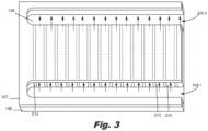
- Fig. 3 is a bottom view of a fluidic ejection die ( Fig. 1A , 100) with inlet and outlet channels (210, 212), according to an example of the principles described herein.
- Fig. 3 depicts a slotted cap substrate (307) and the backside of the channel substrate (106) which defines the channels (212, 210) through which fluid flows.
- Fig. 3 also depicts the underside of the nozzle substrate (104) on which the nozzle openings ( Fig. 1A , 102) are formed.
- Fig. 3 also depicts the ribs (214) that define the channels (212, 210).
- a single instance of many of the components are indicated with a reference number.
- Fig. 3 also depicts the fluid supply slots (326-1, 326-2) that supply fluid to and from the various channels (210, 212).
- the fluid supply slots (326) are formed in the slotted cab substrate (307) and supply fluid to the channels (212, 210).
- fluid going into each of the channels (212, 210) may be the same, i.e., fresh fluid.
- the fluid coming out of the outlet channels (210) may be mixed with waste fluid following activation by the actuation pumps and ejectors.
- the fresh/waste mixed fluid is indicated with a dashed-dot line in Fig. 3 .
- Fig. 4 is a cross-sectional view of a fluidic ejection die (100) with inlet and outlet channels (210, 212), according to an example of the principles described herein.
- Fig. 4 clearly depicts the fluid flow through the channels (212, 210) and the passages (216, 218).
- the flow through the passages (216, 218) is perpendicular to the flow through the channels (210, 210). That is, as the fluid flows through the inlet channels (212), it changes direction perpendicularly as it passes through the inlet passage (216) to be directed to the nozzles.
- the flow through the channels (210, 212) and passages (216, 218) is indicated by arrows in Fig. 4 .
- Fig. 4 depicts nozzles of the array.
- the components of one nozzle in Fig. 4 are depicted with reference numbers.
- the nozzle includes a number of components.
- a nozzle includes an ejection chamber (428) to hold an amount of fluid to be ejected, an opening (102) through which the amount of fluid is ejected, and an ejecting fluid actuator (430), disposed within the ejection chamber (428), to eject the amount of fluid through the opening (102).
- the ejection chamber (428) and nozzle opening (102) may be defined in a nozzle substrate (104) that is deposited on top of a channel substrate ( Fig. 1A , 106).
- the ejecting fluid actuator (430) may include a firing resistor or other thermal device, a piezoelectric element, or other mechanism for ejecting fluid from the ejection chamber (428).
- the ejector (430) may be a firing resistor. The firing resistor heats up in response to an applied voltage. As the firing resistor heats up, a portion of the fluid in the ejection chamber (428) vaporizes to form a bubble. This bubble pushes fluid out the opening (102) and onto the print medium. As the vaporized fluid bubble pops, fluid is drawn into the ejection chamber (428) from a passage (216), and the process repeats.
- the fluidic ejection die (100) may be a thermal inkjet (TIJ) fluidic ejection die (100).
- the ejecting fluid actuator (430) may be a piezoelectric device. As a voltage is applied, the piezoelectric device changes shape which generates a pressure pulse in the ejection chamber (428) that pushes the fluid out the opening (102) and onto the print medium.
- the fluidic ejection die (100) may be a piezoelectric inkjet (PIJ) fluidic ejection die (100).
- each nozzle may include a micro-channel to direct fluid to and from the corresponding ejection chambers (428).
- Such micro-channels may be of sufficiently small size (e.g., of nanometer sized scale, micrometer sized scale, millimeter sized scale, etc.) to facilitate conveyance of small volumes of fluid (e.g., picoliter scale, nanoliter scale, microliter scale, milliliter scale, etc.).
- the micro-channels and the passages (216, 218) that correspond to the nozzle form a micro-recirculation loop.
- a pump fluid actuator (432-1, 432-2) is disposed within a channel to move the fluid to and from the ejection chamber (428).
- Such micro-channels prevent sedimentation of the fluid passing there through and ensures that fresh fluid is available for ejection through the opening (102).
- the fluid actuators, both the ejectors (430) and the pump actuators (432) may be electrostatic membrane actuators, mechanical/impact driven membrane actuators, magneto-strictive drive actuators, or other such elements that may cause displacement of fluid responsive to electrical actuation.
- micro-recirculation loops provide fresh fluid to the ejection chamber (428), thus increasing the effective life of a nozzle. This is because the nozzles operate best when provided with fresh fluid.
- inlet passages (216) which deliver fluid to the ejection chamber (428) receive fluid from an inlet channel (212) which inlet channel (212) is separate from an outlet channel (210) which receives fluid that has already passed by the nozzle and actuation pump (432).
- nozzles that receive fluid from different inlet channels (212-2, 212-3) may pass waste fluid to a shared outlet channel (210-2) albeit by different outlet passages (218-1, 218-2).
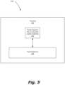
- Fig. 5 is a block diagram of a printing fluid cartridge (534) including a fluidic ejection die (100) with inlet and outlet channels ( Fig. 2B , 210, 212), according to an example of the principles described herein.
- the printing fluid cartridge (534) is used within a printing system to eject a fluid.
- the printing fluid cartridge (534) may be removable from the system for example, as a replaceable cartridge (534).
- the printing fluid cartridge (534) is a substrate-wide printbar and the array of fluidic ejection dies (100) are grouped into fluid ejection devices that are staggered across a width of a substrate on which the fluid is to be deposited.
- the printing fluid cartridge (534) includes a housing (536) to house components of the printing fluid cartridge (534).
- the housing (536) houses a fluid reservoir (538) to supply an amount of fluid to the fluidic ejection die (100).
- fluid flows between the reservoir (538) and the fluidic ejection die (100).
- a portion of the fluid supplied to fluidic ejection die (100) is consumed during operation and fluid not consumed during printing is returned to the fluid reservoir (538).
- the fluid may be ink.
- the ink may be a water-based ultraviolet (UV) ink, pharmaceutical fluid, or 3D printing material, among other fluids.
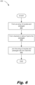
- Fig. 6 is a flowchart of a method (600) for forming a fluidic ejection die ( Fig. 1A , 100) with inlet and outlet channels ( Fig. 2B , 210, 212), according to an example of the principles described herein.
- an array of nozzles and passages (Fig. 2A , 216, 218) are formed (block 601).
- the passages ( Fig. 2A , 216, 218) may be part of a perforated silicon membrane.
- the nozzles, or rather the openings ( Fig. 1A , 102) and the ejection chambers ( Fig. 4 , 428) of the nozzles, may be formed of a nozzle substrate ( Fig.
- forming (block 601) the array of nozzles and passages ( Fig. 2A , 216, 218) may include joining the perforated silicon membrane with the SU-8 nozzle substrate ( Fig. 1A , 104).
- Inlet and outlet channels ( Fig. 2B , 210, 212) are then formed (block 602).
- Forming (block 602) the Inlet and outlet channels ( Fig. 2B , 210, 212) may include adhering ribs ( Fig. 2B , 214) to the backside of the membrane in which the passages ( Fig. 2A , 216, 218) are formed.
- the formation (block 602) may include etching away the channel substrate ( Fig. 1A , 106) to form the ribs ( Fig. 2B , 214) which define in part the inlet and outlet channels ( Fig. 2A , 210, 212).
- each inlet channel ( Fig. 2B , 212) is fluidly connected to a respective plurality of inlet passages ( Fig. 2A , 216) and such that each outlet channel ( Fig. 2B , 210) is fluidly connected to a respective plurality of outlet passages ( Fig. 2A , 218).
- a fluidic ejection die 1) reduces the effects of fluid viscosity by maintaining water concentration in the fluid, 2) facilitates more efficient micro-recirculation within the nozzles, 3) improves nozzle health, 4) provides fluid mixing near the die to increase print quality, 5) convectively cools the fluidic ejection die, 6) removes air bubbles from the fluidic ejection die, 7) allows for re-priming of the nozzle, and 8) improves print quality by separating waste ink from fresh ink.
- the devices disclosed herein may address other matters and deficiencies in a number of technical areas.
Landscapes
- Physics & Mathematics (AREA)
- Geometry (AREA)
- Particle Formation And Scattering Control In Inkjet Printers (AREA)
- Ink Jet (AREA)
- Coating Apparatus (AREA)
Claims (15)
- Fluidausstoßdüse (100), die umfasst:eine Anordnung von Spritzdüsen, wobei jede Spritzdüse umfasst: eine Ausstoßkammer (428);eine Öffnung (102); undein Fluidbedienungselement (430), das innerhalb der Ausstoßkammer eingerichtet ist,einen Einlassdurchgang (216), der in einem Substrat (106) ausgebildet und dazu konfiguriert ist, Fluid in die Ausstoßkammer abzugeben, undeinen Auslassdurchgang (218), der in dem Substrat ausgebildet und dazu konfiguriert ist, Fluid aus der Ausstoßkammer abzugeben, undeine Anordnung von Kanälen, die auf einer Rückoberfläche des Substrats ausgebildet ist, wobei die Anordnung von Kanälen in Einlasskanäle (212) und Auslasskanäle (210) unterteilt ist,wobei:jeder Einlasskanal mit einer jeweiligen Vielzahl von Einlassdurchgängen fluidisch verbunden ist, undjeder Auslasskanal mit einer jeweiligen Vielzahl von Auslassdurchgängen fluidisch verbunden ist;dadurch gekennzeichnet, dass die Fluidausstoßvorrichtung umfasst:eine Mikro-Umwälzpumpe (220, 432), die zwischen jedem Einlassdurchgang und Auslassdurchgang eingerichtet und dazu konfiguriert ist, das Fluid in einer pulsierenden Weise in diesen Einlassdurchgang hinein und aus diesem Auslassdurchgang heraus zu zirkulieren, um Wirbel in dem Fluid in einem entsprechenden Auslasskanal zu verursachen.
- Fluidausstoßdüse nach Anspruch 1, wobei jeder Einlasskanal zwischen einem Paar von Auslasskanälen eingerichtet ist.
- Fluidausstoßdüse nach Anspruch 1, wobei angrenzende Einlassdurchgänge, die mit einem gemeinsamen Einlasskanal fluidisch verbunden sind, mit jeweiligen Auslasskanälen, die sich auf gegenüberliegenden Seiten des gemeinsamen Einlasskanals befinden, fluidisch verbunden sind.
- Fluidausstoßdüse nach Anspruch 1, wobei die Einlasskanäle und die Auslasskanäle mit einem gemeinsamen genutzten Einlassfluidversorgungsschlitz fluidisch gekoppelt sind.
- Fluidausstoßdüse nach Anspruch 4, wobei die Einlasskanäle und die Auslasskanäle dazu konfiguriert sind, Frischfluid aus dem gemeinsam genutzten Einlassfluidversorgungsschlitz zu empfangen.
- Fluidausstoßdüse nach Anspruch 1, wobei die Einlasskanäle und die Auslasskanäle mit einem gemeinsamen genutzten Auslassfluidversorgungsschlitz fluidisch gekoppelt sind.
- Fluidausstoßdüse nach Anspruch 6, wobei:die Einlasskanäle dazu konfiguriert sind, überschüssiges Frischfluid an den gemeinsam genutzten Auslassfluidversorgungsschlitz weiterzuleiten; unddie Auslasskanäle dazu konfiguriert sind, überschüssiges Frischfluid und Abfallfluid an den gemeinsam genutzten Auslassfluidversorgungsschlitz weiterzuleiten.
- Fluidausstoßdüse nach Anspruch 1, wobei die Einlass- und Auslassdurchgänge in einer perforierten Schicht des Substrats ausgebildet sind.
- Fluidausstoßdüse nach Anspruch 1, wobei jede Sprühdüse ferner einen Mikro-Rezirkulationskanal umfasst, der dazu konfiguriert ist, Fluid zu und von der entsprechenden Ausstoßkammer zu leiten.
- Druckfluidpatrone, die umfasst:eine Einhausung;ein Reservoir, das innerhalb der Einhausung eingerichtet ist, das dazu konfiguriert ist, ein Fluid, das auf ein Substrat abzuscheiden ist, zu enthalten;und eine Anordnung von Fluidausstoßdüsen nach Anspruch 1, die auf der Einhausung eingerichtet sind.
- Druckfluidpatrone nach Anspruch 10, wobei die Anordnung von Kanälen zwischen Einlasskanälen und Auslasskanälen wechselt.
- Druckfluidpatrone nach Anspruch 10, wobei:die Druckfluidpatrone ein seitenbreiter Druckbalken ist; unddie Anordnung von Fluidausstoßdüsen zu Fluidausstoßvorrichtungen gruppiert ist, wobei die Fluidausstoßvorrichtungen über eine Breite einer Seite von Medien, auf der das Fluid abzuscheiden ist, versetzt aufgebaut sind.
- Druckfluidpatrone nach Anspruch 10, wobei die Anordnung von Kanälen derart konfiguriert ist, dass der Fluidfluss durch die Anordnung von Kanälen senkrecht zu dem Fluidfluss in den Einlassdurchgängen und den Auslassdurchgängen verläuft.
- Verfahren zum Herstellen einer Fluidausstoßdüse (100) nach einem der Ansprüche 1 bis 9, wobei das Verfahren umfasst:
Ausbilden einer Anordnung von Sprühdüsen in einem Substrat (106), das für jede Sprühdüse die Schritte umfasst:Ausbilden einer Ausstoßkammer (428), einer Öffnung (102), eines Einlassdurchgangs (216), der dazu konfiguriert ist, Fluid in die Ausstoßkammer abzugeben, und eines Auslassdurchgangs (218), der dazu konfiguriert ist, Fluid aus der Ausstoßkammer abzugeben, undFixieren eines jeweiligen Fluidbedienungselements (430) in der Ausstoßkammer jeder Sprühdüse,Ausbilden einer Anordnung von Kanälen auf einer Rückoberfläche des Substrats, wobei die Anordnung von Kanälen in Einlasskanäle (212) und Auslasskanäle (210) unterteilt ist, undjeder Einlasskanal mit einer jeweiligen Vielzahl von Einlassdurchgängen fluidisch verbunden ist, undjeder Auslasskanal mit einer jeweiligen Vielzahl von Auslassdurchgängen fluidisch verbunden ist, undAusbilden einer Mikro-Umwälzpumpe (220, 432), die zwischen jedem Einlassdurchgang und Auslassdurchgang eingerichtet ist, um Fluid in einen entsprechenden Einlassdurchgang hinein und aus einem entsprechenden Auslassdurchgang heraus in einer pulsierenden Weise zu zirkulieren, um Wirbel in dem Fluid in dem Auslasskanal, der mit dem entsprechenden Auslassdurchgang verbunden ist, zu verursachen. - Verfahren nach Anspruch 14, wobei das Ausbilden der Anzahl von Kanälen auf dem Substrat ein Ätzen der Rückoberfläche des Substrats umfasst.
Applications Claiming Priority (1)
| Application Number | Priority Date | Filing Date | Title |
|---|---|---|---|
| PCT/US2017/050901 WO2019050540A1 (en) | 2017-09-11 | 2017-09-11 | FLUIDIC MATRIX WITH INPUT AND OUTPUT CHANNELS |
Publications (3)
| Publication Number | Publication Date |
|---|---|
| EP3661750A1 EP3661750A1 (de) | 2020-06-10 |
| EP3661750A4 EP3661750A4 (de) | 2021-04-07 |
| EP3661750B1 true EP3661750B1 (de) | 2024-07-24 |
Family
ID=65634918
Family Applications (1)
| Application Number | Title | Priority Date | Filing Date |
|---|---|---|---|
| EP17924473.6A Active EP3661750B1 (de) | 2017-09-11 | 2017-09-11 | Fluidische matrizen mit einlass- und auslasskanälen |
Country Status (5)
| Country | Link |
|---|---|
| US (1) | US11225074B2 (de) |
| EP (1) | EP3661750B1 (de) |
| JP (1) | JP6945064B2 (de) |
| TW (1) | TWI715867B (de) |
| WO (1) | WO2019050540A1 (de) |
Families Citing this family (4)
| Publication number | Priority date | Publication date | Assignee | Title |
|---|---|---|---|---|
| EP3755537B1 (de) * | 2019-04-29 | 2023-04-26 | Hewlett-Packard Development Company, L.P. | Elektrisch mit fluidischen matrizen gekoppelte leitende elemente |
| WO2021162708A1 (en) | 2020-02-14 | 2021-08-19 | Hewlett-Packard Development Company, L.P. | Continuous fluid recirculation and recirculation on-demand prior to firing for thermal ejection of fluid having concentration of solids |
| JP7547096B2 (ja) * | 2020-06-26 | 2024-09-09 | キヤノン株式会社 | 液体吐出ヘッド及び液体吐出装置 |
| EP4274740A4 (de) * | 2021-01-11 | 2024-02-21 | Hewlett-Packard Development Company, L.P. | Anpassung von elektrisch leitfähigen leitungswiderständen an schalter in fluidischen matrizen |
Family Cites Families (20)
| Publication number | Priority date | Publication date | Assignee | Title |
|---|---|---|---|---|
| US6055002A (en) | 1997-06-03 | 2000-04-25 | Eastman Kodak Company | Microfluidic printing with ink flow regulation |
| JP3846083B2 (ja) | 1998-02-06 | 2006-11-15 | ブラザー工業株式会社 | インクジェット記録装置 |
| US6364466B1 (en) | 2000-11-30 | 2002-04-02 | Hewlett-Packard Company | Particle tolerant ink-feed channel structure for fully integrated inkjet printhead |
| JP2012532772A (ja) | 2009-07-10 | 2012-12-20 | フジフィルム ディマティックス, インコーポレイテッド | 高密度実装のためのmemsジェット射出構造 |
| US9090084B2 (en) | 2010-05-21 | 2015-07-28 | Hewlett-Packard Development Company, L.P. | Fluid ejection device including recirculation system |
| KR101686286B1 (ko) * | 2010-10-28 | 2016-12-28 | 휴렛-팩커드 디벨롭먼트 컴퍼니, 엘.피. | 순환 펌프를 구비한 유체 분사 어셈블리 |
| US8657420B2 (en) * | 2010-12-28 | 2014-02-25 | Fujifilm Corporation | Fluid recirculation in droplet ejection devices |
| US9315019B2 (en) * | 2011-04-29 | 2016-04-19 | Hewlett-Packard Development Company, L.P. | Systems and methods for degassing fluid |
| CN103619600A (zh) * | 2011-06-29 | 2014-03-05 | 惠普发展公司,有限责任合伙企业 | 压电打印头轨迹布局 |
| US8721042B2 (en) | 2011-07-27 | 2014-05-13 | Eastman Kodak Company | Inkjet printhead with layered ceramic mounting substrate |
| WO2013134322A1 (en) | 2012-03-05 | 2013-09-12 | Fujifilm Dimatix, Inc. | Recirculation of ink |
| US20130292089A1 (en) | 2012-05-01 | 2013-11-07 | Norcross Corporation | Dual passage concentric tube heat exchanger for cooling/heating of fluid in a low pressure system |
| US9381739B2 (en) | 2013-02-28 | 2016-07-05 | Hewlett-Packard Development Company, L.P. | Fluid ejection assembly with circulation pump |
| JP2015150881A (ja) | 2014-02-19 | 2015-08-24 | 京セラ株式会社 | 液体吐出ヘッド、およびそれを用いた記録装置 |
| JP6410528B2 (ja) * | 2014-08-29 | 2018-10-24 | キヤノン株式会社 | 液体吐出ヘッドとそれを用いたヘッドユニット |
| JP2016159514A (ja) | 2015-03-02 | 2016-09-05 | 富士フイルム株式会社 | 液体吐出装置、及び液体吐出ヘッドの異物排出方法 |
| JP2017001247A (ja) | 2015-06-09 | 2017-01-05 | 株式会社リコー | 液滴吐出装置及び画像形成装置 |
| US9902157B2 (en) | 2016-01-08 | 2018-02-27 | Canon Kabushiki Kaisha | Liquid ejection substrate, liquid ejection head, and liquid ejection apparatus |
| JP7013124B2 (ja) | 2016-01-08 | 2022-01-31 | キヤノン株式会社 | 液体吐出ヘッドの製造方法 |
| JP6719918B2 (ja) | 2016-02-17 | 2020-07-08 | キヤノン株式会社 | 液体吐出ヘッド及び液体吐出装置 |
-
2017
- 2017-09-11 US US16/500,431 patent/US11225074B2/en active Active
- 2017-09-11 WO PCT/US2017/050901 patent/WO2019050540A1/en not_active Ceased
- 2017-09-11 EP EP17924473.6A patent/EP3661750B1/de active Active
- 2017-09-11 JP JP2020514588A patent/JP6945064B2/ja not_active Expired - Fee Related
-
2018
- 2018-09-11 TW TW107131877A patent/TWI715867B/zh not_active IP Right Cessation
Also Published As
| Publication number | Publication date |
|---|---|
| JP2020533205A (ja) | 2020-11-19 |
| EP3661750A1 (de) | 2020-06-10 |
| TWI715867B (zh) | 2021-01-11 |
| JP6945064B2 (ja) | 2021-10-06 |
| WO2019050540A1 (en) | 2019-03-14 |
| EP3661750A4 (de) | 2021-04-07 |
| US11225074B2 (en) | 2022-01-18 |
| US20200198340A1 (en) | 2020-06-25 |
| TW201927583A (zh) | 2019-07-16 |
Similar Documents
| Publication | Publication Date | Title |
|---|---|---|
| US11155086B2 (en) | Fluidic ejection devices with enclosed cross-channels | |
| US11654680B2 (en) | Fluidic ejection dies with enclosed cross-channels | |
| US11987055B2 (en) | Fluidic dies | |
| EP3661750B1 (de) | Fluidische matrizen mit einlass- und auslasskanälen | |
| US11390075B2 (en) | Fluidic dies | |
| CN112041171A (zh) | 用微泵和基于压力差的流体流进行流体喷射 | |
| EP3691903B1 (de) | Flüssigkeitszirkulation und -ausstoss | |
| CN109641456B (zh) | 包括流体输出通道的流体喷射设备 | |
| JP7317560B2 (ja) | 液体吐出ヘッド、液体吐出モジュールおよび液体吐出装置 |
Legal Events
| Date | Code | Title | Description |
|---|---|---|---|
| STAA | Information on the status of an ep patent application or granted ep patent |
Free format text: STATUS: THE INTERNATIONAL PUBLICATION HAS BEEN MADE |
|
| PUAI | Public reference made under article 153(3) epc to a published international application that has entered the european phase |
Free format text: ORIGINAL CODE: 0009012 |
|
| STAA | Information on the status of an ep patent application or granted ep patent |
Free format text: STATUS: REQUEST FOR EXAMINATION WAS MADE |
|
| 17P | Request for examination filed |
Effective date: 20200305 |
|
| AK | Designated contracting states |
Kind code of ref document: A1 Designated state(s): AL AT BE BG CH CY CZ DE DK EE ES FI FR GB GR HR HU IE IS IT LI LT LU LV MC MK MT NL NO PL PT RO RS SE SI SK SM TR |
|
| AX | Request for extension of the european patent |
Extension state: BA ME |
|
| DAV | Request for validation of the european patent (deleted) | ||
| DAX | Request for extension of the european patent (deleted) | ||
| A4 | Supplementary search report drawn up and despatched |
Effective date: 20210304 |
|
| RIC1 | Information provided on ipc code assigned before grant |
Ipc: B41J 2/14 20060101AFI20210226BHEP |
|
| STAA | Information on the status of an ep patent application or granted ep patent |
Free format text: STATUS: EXAMINATION IS IN PROGRESS |
|
| 17Q | First examination report despatched |
Effective date: 20220929 |
|
| GRAP | Despatch of communication of intention to grant a patent |
Free format text: ORIGINAL CODE: EPIDOSNIGR1 |
|
| STAA | Information on the status of an ep patent application or granted ep patent |
Free format text: STATUS: GRANT OF PATENT IS INTENDED |
|
| INTG | Intention to grant announced |
Effective date: 20240426 |
|
| GRAS | Grant fee paid |
Free format text: ORIGINAL CODE: EPIDOSNIGR3 |
|
| GRAA | (expected) grant |
Free format text: ORIGINAL CODE: 0009210 |
|
| STAA | Information on the status of an ep patent application or granted ep patent |
Free format text: STATUS: THE PATENT HAS BEEN GRANTED |
|
| AK | Designated contracting states |
Kind code of ref document: B1 Designated state(s): AL AT BE BG CH CY CZ DE DK EE ES FI FR GB GR HR HU IE IS IT LI LT LU LV MC MK MT NL NO PL PT RO RS SE SI SK SM TR |
|
| REG | Reference to a national code |
Ref country code: GB Ref legal event code: FG4D |
|
| REG | Reference to a national code |
Ref country code: CH Ref legal event code: EP |
|
| REG | Reference to a national code |
Ref country code: DE Ref legal event code: R096 Ref document number: 602017083614 Country of ref document: DE |
|
| REG | Reference to a national code |
Ref country code: IE Ref legal event code: FG4D |
|
| REG | Reference to a national code |
Ref country code: LT Ref legal event code: MG9D |
|
| REG | Reference to a national code |
Ref country code: NL Ref legal event code: MP Effective date: 20240724 |
|
| PG25 | Lapsed in a contracting state [announced via postgrant information from national office to epo] |
Ref country code: PT Free format text: LAPSE BECAUSE OF FAILURE TO SUBMIT A TRANSLATION OF THE DESCRIPTION OR TO PAY THE FEE WITHIN THE PRESCRIBED TIME-LIMIT Effective date: 20241125 |
|
| REG | Reference to a national code |
Ref country code: AT Ref legal event code: MK05 Ref document number: 1705976 Country of ref document: AT Kind code of ref document: T Effective date: 20240724 |
|
| PG25 | Lapsed in a contracting state [announced via postgrant information from national office to epo] |
Ref country code: NL Free format text: LAPSE BECAUSE OF FAILURE TO SUBMIT A TRANSLATION OF THE DESCRIPTION OR TO PAY THE FEE WITHIN THE PRESCRIBED TIME-LIMIT Effective date: 20240724 |
|
| PG25 | Lapsed in a contracting state [announced via postgrant information from national office to epo] |
Ref country code: PT Free format text: LAPSE BECAUSE OF FAILURE TO SUBMIT A TRANSLATION OF THE DESCRIPTION OR TO PAY THE FEE WITHIN THE PRESCRIBED TIME-LIMIT Effective date: 20241125 Ref country code: NL Free format text: LAPSE BECAUSE OF FAILURE TO SUBMIT A TRANSLATION OF THE DESCRIPTION OR TO PAY THE FEE WITHIN THE PRESCRIBED TIME-LIMIT Effective date: 20240724 |
|
| PG25 | Lapsed in a contracting state [announced via postgrant information from national office to epo] |
Ref country code: NO Free format text: LAPSE BECAUSE OF FAILURE TO SUBMIT A TRANSLATION OF THE DESCRIPTION OR TO PAY THE FEE WITHIN THE PRESCRIBED TIME-LIMIT Effective date: 20241024 |
|
| PG25 | Lapsed in a contracting state [announced via postgrant information from national office to epo] |
Ref country code: GR Free format text: LAPSE BECAUSE OF FAILURE TO SUBMIT A TRANSLATION OF THE DESCRIPTION OR TO PAY THE FEE WITHIN THE PRESCRIBED TIME-LIMIT Effective date: 20241025 Ref country code: FI Free format text: LAPSE BECAUSE OF FAILURE TO SUBMIT A TRANSLATION OF THE DESCRIPTION OR TO PAY THE FEE WITHIN THE PRESCRIBED TIME-LIMIT Effective date: 20240724 Ref country code: PL Free format text: LAPSE BECAUSE OF FAILURE TO SUBMIT A TRANSLATION OF THE DESCRIPTION OR TO PAY THE FEE WITHIN THE PRESCRIBED TIME-LIMIT Effective date: 20240724 |
|
| PG25 | Lapsed in a contracting state [announced via postgrant information from national office to epo] |
Ref country code: BG Free format text: LAPSE BECAUSE OF FAILURE TO SUBMIT A TRANSLATION OF THE DESCRIPTION OR TO PAY THE FEE WITHIN THE PRESCRIBED TIME-LIMIT Effective date: 20240724 |
|
| PG25 | Lapsed in a contracting state [announced via postgrant information from national office to epo] |
Ref country code: LV Free format text: LAPSE BECAUSE OF FAILURE TO SUBMIT A TRANSLATION OF THE DESCRIPTION OR TO PAY THE FEE WITHIN THE PRESCRIBED TIME-LIMIT Effective date: 20240724 |
|
| PG25 | Lapsed in a contracting state [announced via postgrant information from national office to epo] |
Ref country code: IS Free format text: LAPSE BECAUSE OF FAILURE TO SUBMIT A TRANSLATION OF THE DESCRIPTION OR TO PAY THE FEE WITHIN THE PRESCRIBED TIME-LIMIT Effective date: 20241124 Ref country code: AT Free format text: LAPSE BECAUSE OF FAILURE TO SUBMIT A TRANSLATION OF THE DESCRIPTION OR TO PAY THE FEE WITHIN THE PRESCRIBED TIME-LIMIT Effective date: 20240724 |
|
| PG25 | Lapsed in a contracting state [announced via postgrant information from national office to epo] |
Ref country code: HR Free format text: LAPSE BECAUSE OF FAILURE TO SUBMIT A TRANSLATION OF THE DESCRIPTION OR TO PAY THE FEE WITHIN THE PRESCRIBED TIME-LIMIT Effective date: 20240724 |
|
| PG25 | Lapsed in a contracting state [announced via postgrant information from national office to epo] |
Ref country code: RS Free format text: LAPSE BECAUSE OF FAILURE TO SUBMIT A TRANSLATION OF THE DESCRIPTION OR TO PAY THE FEE WITHIN THE PRESCRIBED TIME-LIMIT Effective date: 20241024 Ref country code: ES Free format text: LAPSE BECAUSE OF FAILURE TO SUBMIT A TRANSLATION OF THE DESCRIPTION OR TO PAY THE FEE WITHIN THE PRESCRIBED TIME-LIMIT Effective date: 20240724 |
|
| PG25 | Lapsed in a contracting state [announced via postgrant information from national office to epo] |
Ref country code: RS Free format text: LAPSE BECAUSE OF FAILURE TO SUBMIT A TRANSLATION OF THE DESCRIPTION OR TO PAY THE FEE WITHIN THE PRESCRIBED TIME-LIMIT Effective date: 20241024 Ref country code: PL Free format text: LAPSE BECAUSE OF FAILURE TO SUBMIT A TRANSLATION OF THE DESCRIPTION OR TO PAY THE FEE WITHIN THE PRESCRIBED TIME-LIMIT Effective date: 20240724 Ref country code: NO Free format text: LAPSE BECAUSE OF FAILURE TO SUBMIT A TRANSLATION OF THE DESCRIPTION OR TO PAY THE FEE WITHIN THE PRESCRIBED TIME-LIMIT Effective date: 20241024 Ref country code: LV Free format text: LAPSE BECAUSE OF FAILURE TO SUBMIT A TRANSLATION OF THE DESCRIPTION OR TO PAY THE FEE WITHIN THE PRESCRIBED TIME-LIMIT Effective date: 20240724 Ref country code: IS Free format text: LAPSE BECAUSE OF FAILURE TO SUBMIT A TRANSLATION OF THE DESCRIPTION OR TO PAY THE FEE WITHIN THE PRESCRIBED TIME-LIMIT Effective date: 20241124 Ref country code: HR Free format text: LAPSE BECAUSE OF FAILURE TO SUBMIT A TRANSLATION OF THE DESCRIPTION OR TO PAY THE FEE WITHIN THE PRESCRIBED TIME-LIMIT Effective date: 20240724 Ref country code: GR Free format text: LAPSE BECAUSE OF FAILURE TO SUBMIT A TRANSLATION OF THE DESCRIPTION OR TO PAY THE FEE WITHIN THE PRESCRIBED TIME-LIMIT Effective date: 20241025 Ref country code: FI Free format text: LAPSE BECAUSE OF FAILURE TO SUBMIT A TRANSLATION OF THE DESCRIPTION OR TO PAY THE FEE WITHIN THE PRESCRIBED TIME-LIMIT Effective date: 20240724 Ref country code: ES Free format text: LAPSE BECAUSE OF FAILURE TO SUBMIT A TRANSLATION OF THE DESCRIPTION OR TO PAY THE FEE WITHIN THE PRESCRIBED TIME-LIMIT Effective date: 20240724 Ref country code: BG Free format text: LAPSE BECAUSE OF FAILURE TO SUBMIT A TRANSLATION OF THE DESCRIPTION OR TO PAY THE FEE WITHIN THE PRESCRIBED TIME-LIMIT Effective date: 20240724 Ref country code: AT Free format text: LAPSE BECAUSE OF FAILURE TO SUBMIT A TRANSLATION OF THE DESCRIPTION OR TO PAY THE FEE WITHIN THE PRESCRIBED TIME-LIMIT Effective date: 20240724 |
|
| PG25 | Lapsed in a contracting state [announced via postgrant information from national office to epo] |
Ref country code: RO Free format text: LAPSE BECAUSE OF FAILURE TO SUBMIT A TRANSLATION OF THE DESCRIPTION OR TO PAY THE FEE WITHIN THE PRESCRIBED TIME-LIMIT Effective date: 20240724 Ref country code: DK Free format text: LAPSE BECAUSE OF FAILURE TO SUBMIT A TRANSLATION OF THE DESCRIPTION OR TO PAY THE FEE WITHIN THE PRESCRIBED TIME-LIMIT Effective date: 20240724 Ref country code: SM Free format text: LAPSE BECAUSE OF FAILURE TO SUBMIT A TRANSLATION OF THE DESCRIPTION OR TO PAY THE FEE WITHIN THE PRESCRIBED TIME-LIMIT Effective date: 20240724 |
|
| PG25 | Lapsed in a contracting state [announced via postgrant information from national office to epo] |
Ref country code: MC Free format text: LAPSE BECAUSE OF FAILURE TO SUBMIT A TRANSLATION OF THE DESCRIPTION OR TO PAY THE FEE WITHIN THE PRESCRIBED TIME-LIMIT Effective date: 20240724 Ref country code: EE Free format text: LAPSE BECAUSE OF FAILURE TO SUBMIT A TRANSLATION OF THE DESCRIPTION OR TO PAY THE FEE WITHIN THE PRESCRIBED TIME-LIMIT Effective date: 20240724 |
|
| PG25 | Lapsed in a contracting state [announced via postgrant information from national office to epo] |
Ref country code: CZ Free format text: LAPSE BECAUSE OF FAILURE TO SUBMIT A TRANSLATION OF THE DESCRIPTION OR TO PAY THE FEE WITHIN THE PRESCRIBED TIME-LIMIT Effective date: 20240724 |
|
| REG | Reference to a national code |
Ref country code: DE Ref legal event code: R097 Ref document number: 602017083614 Country of ref document: DE |
|
| PG25 | Lapsed in a contracting state [announced via postgrant information from national office to epo] |
Ref country code: IT Free format text: LAPSE BECAUSE OF FAILURE TO SUBMIT A TRANSLATION OF THE DESCRIPTION OR TO PAY THE FEE WITHIN THE PRESCRIBED TIME-LIMIT Effective date: 20240724 Ref country code: SK Free format text: LAPSE BECAUSE OF FAILURE TO SUBMIT A TRANSLATION OF THE DESCRIPTION OR TO PAY THE FEE WITHIN THE PRESCRIBED TIME-LIMIT Effective date: 20240724 |
|
| REG | Reference to a national code |
Ref country code: CH Ref legal event code: PL |
|
| PG25 | Lapsed in a contracting state [announced via postgrant information from national office to epo] |
Ref country code: LU Free format text: LAPSE BECAUSE OF NON-PAYMENT OF DUE FEES Effective date: 20240911 |
|
| PLBE | No opposition filed within time limit |
Free format text: ORIGINAL CODE: 0009261 |
|
| STAA | Information on the status of an ep patent application or granted ep patent |
Free format text: STATUS: NO OPPOSITION FILED WITHIN TIME LIMIT |
|
| GBPC | Gb: european patent ceased through non-payment of renewal fee |
Effective date: 20241024 |
|
| 26N | No opposition filed |
Effective date: 20250425 |
|
| PG25 | Lapsed in a contracting state [announced via postgrant information from national office to epo] |
Ref country code: GB Free format text: LAPSE BECAUSE OF NON-PAYMENT OF DUE FEES Effective date: 20241024 |
|
| REG | Reference to a national code |
Ref country code: BE Ref legal event code: MM Effective date: 20240930 |
|
| PG25 | Lapsed in a contracting state [announced via postgrant information from national office to epo] |
Ref country code: BE Free format text: LAPSE BECAUSE OF NON-PAYMENT OF DUE FEES Effective date: 20240930 |
|
| PG25 | Lapsed in a contracting state [announced via postgrant information from national office to epo] |
Ref country code: FR Free format text: LAPSE BECAUSE OF NON-PAYMENT OF DUE FEES Effective date: 20240924 |
|
| PG25 | Lapsed in a contracting state [announced via postgrant information from national office to epo] |
Ref country code: CH Free format text: LAPSE BECAUSE OF NON-PAYMENT OF DUE FEES Effective date: 20240930 |
|
| PG25 | Lapsed in a contracting state [announced via postgrant information from national office to epo] |
Ref country code: IE Free format text: LAPSE BECAUSE OF NON-PAYMENT OF DUE FEES Effective date: 20240911 |
|
| PG25 | Lapsed in a contracting state [announced via postgrant information from national office to epo] |
Ref country code: SE Free format text: LAPSE BECAUSE OF FAILURE TO SUBMIT A TRANSLATION OF THE DESCRIPTION OR TO PAY THE FEE WITHIN THE PRESCRIBED TIME-LIMIT Effective date: 20240724 |
|
| PGFP | Annual fee paid to national office [announced via postgrant information from national office to epo] |
Ref country code: DE Payment date: 20250820 Year of fee payment: 9 |
|
| PG25 | Lapsed in a contracting state [announced via postgrant information from national office to epo] |
Ref country code: CY Free format text: LAPSE BECAUSE OF FAILURE TO SUBMIT A TRANSLATION OF THE DESCRIPTION OR TO PAY THE FEE WITHIN THE PRESCRIBED TIME-LIMIT; INVALID AB INITIO Effective date: 20170911 |
|
| PG25 | Lapsed in a contracting state [announced via postgrant information from national office to epo] |
Ref country code: HU Free format text: LAPSE BECAUSE OF FAILURE TO SUBMIT A TRANSLATION OF THE DESCRIPTION OR TO PAY THE FEE WITHIN THE PRESCRIBED TIME-LIMIT; INVALID AB INITIO Effective date: 20170911 |