EP3661822B1 - Système de freinage hydraulique passif sans stockage - Google Patents
Système de freinage hydraulique passif sans stockage Download PDFInfo
- Publication number
- EP3661822B1 EP3661822B1 EP18746913.5A EP18746913A EP3661822B1 EP 3661822 B1 EP3661822 B1 EP 3661822B1 EP 18746913 A EP18746913 A EP 18746913A EP 3661822 B1 EP3661822 B1 EP 3661822B1
- Authority
- EP
- European Patent Office
- Prior art keywords
- damping element
- braking system
- pressure
- hydraulic
- hydraulic braking
- Prior art date
- Legal status (The legal status is an assumption and is not a legal conclusion. Google has not performed a legal analysis and makes no representation as to the accuracy of the status listed.)
- Active
Links
Images
Classifications
-
- B—PERFORMING OPERATIONS; TRANSPORTING
- B60—VEHICLES IN GENERAL
- B60T—VEHICLE BRAKE CONTROL SYSTEMS OR PARTS THEREOF; BRAKE CONTROL SYSTEMS OR PARTS THEREOF, IN GENERAL; ARRANGEMENT OF BRAKING ELEMENTS ON VEHICLES IN GENERAL; PORTABLE DEVICES FOR PREVENTING UNWANTED MOVEMENT OF VEHICLES; VEHICLE MODIFICATIONS TO FACILITATE COOLING OF BRAKES
- B60T13/00—Transmitting braking action from initiating means to ultimate brake actuator with power assistance or drive; Brake systems incorporating such transmitting means, e.g. air-pressure brake systems
- B60T13/10—Transmitting braking action from initiating means to ultimate brake actuator with power assistance or drive; Brake systems incorporating such transmitting means, e.g. air-pressure brake systems with fluid assistance, drive, or release
- B60T13/12—Transmitting braking action from initiating means to ultimate brake actuator with power assistance or drive; Brake systems incorporating such transmitting means, e.g. air-pressure brake systems with fluid assistance, drive, or release the fluid being liquid
- B60T13/16—Transmitting braking action from initiating means to ultimate brake actuator with power assistance or drive; Brake systems incorporating such transmitting means, e.g. air-pressure brake systems with fluid assistance, drive, or release the fluid being liquid using pumps directly, i.e. without interposition of accumulators or reservoirs
- B60T13/168—Arrangements for pressure supply
-
- B—PERFORMING OPERATIONS; TRANSPORTING
- B60—VEHICLES IN GENERAL
- B60T—VEHICLE BRAKE CONTROL SYSTEMS OR PARTS THEREOF; BRAKE CONTROL SYSTEMS OR PARTS THEREOF, IN GENERAL; ARRANGEMENT OF BRAKING ELEMENTS ON VEHICLES IN GENERAL; PORTABLE DEVICES FOR PREVENTING UNWANTED MOVEMENT OF VEHICLES; VEHICLE MODIFICATIONS TO FACILITATE COOLING OF BRAKES
- B60T17/00—Component parts, details, or accessories of power brake systems not covered by groups B60T8/00, B60T13/00 or B60T15/00, or presenting other characteristic features
- B60T17/04—Arrangements of piping, valves in the piping, e.g. cut-off valves, couplings or air hoses
Definitions
- the invention relates to a passive accumulator-less hydraulic brake system in which a hydraulic pump driven by a motor generates an oil pressure which feeds a pressure line of a hydraulic circuit via a check valve, which supplies at least one brake caliper connected thereto with a hydraulic feed pressure.
- the field of application of the invention extends to vehicles that are equipped with a passive accumulator-less hydraulic brake system.
- a passive accumulator-less hydraulic brake system In such a brake system, there is no need for an otherwise conventional hydraulic pressure accumulator, so that only the pressure in the hydraulic line system is used to maintain the release force required for the brakes in the non-actuated state.
- U.S. 2013/241275 A1 discloses a hydraulic brake system with an accumulator, in which a hydraulic pump driven by a motor generates an oil pressure that feeds a pressure line of a hydraulic circuit via a check valve, which supplies at least one brake caliper connected thereto with a hydraulic feed pressure, with a spring-loaded pressure line in the hydraulic circuit Damping element is connected to buffer a leakage compensation oil volume.
- a hydraulic, accumulator-less, slip-controlled brake system emerges, which has a power booster connected upstream of the master brake cylinder, a hydraulic pump with a controllable electric motor, and an overflow reservoir connected to the inlet of the hydraulic pump.
- the input line of the hydraulic pump is connected to the supply tank at such a point, the position of which corresponds to a minimum liquid volume in the supply tank.
- the motor and pump control of accumulator-less hydraulic brake systems is designed in such a way that the strongest possible force generator is safely released and remains so. This state must be maintained until the next braking request.
- Such a design based on the strongest force generator is therefore necessary in order to prevent brake pads from being unintentionally applied to brake discs. This prevents the disc brake from overheating.
- hydraulic components such as valves in particular, are not absolutely tight. A few drops of hydraulic oil per minute of leakage per hydraulic component are regularly permissible.
- the pressure in the pressure line of the hydraulic circuit and thus in the brake force generator falls.
- the hydraulic pump is usually put into operation.
- this switching on and off process of the hydraulic pump takes place in the so-called stiff area of the brake force generator. As a result, almost no oil volume is available to compensate for the leakage.
- the invention includes the technical teaching that a spring-loaded damping element is connected to the pressure line of the hydraulic circuit of a passive accumulator-less hydraulic brake system for the intermediate buffering of a small leakage compensation oil volume.
- a cylinder chamber for the leakage compensation oil volume is preferably formed in the damping element between a cylinder head and a spring-loaded piston, which chamber buffers 0.3 to 1 cm 3 , preferably between 0.4 to 0.8 cm 3 oil.
- the spring strength of the spring-loaded damping element should preferably be dimensioned in such a way that the leakage compensation oil volume is temporarily buffered between a restart pressure and a switch-off pressure of the motor of the hydraulic pump. This avoids starting the motor and pump combination that is only caused by leakage. If, for example, the pretensioning force of the spring-loaded damping element is adjusted to a resulting pressure of 80 bar, which corresponds to the (re-)switch-on pressure, the switch-off pressure can be set to 105 bar.
- the damping element can be dimensioned with an internal stop at approx. 110 bar. The result of this is that the stiff area of the characteristic curve of the braking force generator is dampened. Depending on the tolerance situation, intermediate buffering of the above-mentioned, preferably 0.4 cm 3 to 0.8 cm 3 suffices. If there is a leak in the braking system, this buffered oil is used first before the motor and pump combination has to start up again.
- the spring force-loaded damping element is designed to be adjustable with regard to the spring strength that can be applied to the hydraulic circuit. In this way, a system-related adjustment of the prestressing force can be achieved in a simple manner.
- a disk spring assembly for spring loading which comes to rest against a piston that is dynamically sealed and movably accommodated axially in a damping element housing on the side opposite the hydraulic pressure.
- the piston together with the cylinder head, forms a piston-cylinder arrangement which is subjected to spring force on the one hand and pressure on the other hand. This achieves the damping function of the damping element.
- the disk spring package consists of a number of individual disk springs which, when arranged in a package-like arrangement, can produce a spring force that is matched to the prevailing hydraulic pressure with a sufficient piston stroke.
- the cylinder head of the piston-cylinder arrangement is preferably screwed into a pot-shaped damping element housing in order to form a compact structural unit which is easy to assemble.
- the screw connection offers the further advantage that the spring strength of the plate spring assembly can be adjusted in terms of its preload via the screwing depth of the cylinder head into the pot-shaped damping element housing.
- a detachable securing element This can be a locking screw, for example, which exerts a clamping effect on the screw connection.
- a coaxial connection hole should be made directly in the cylinder head for connection to the pressure line of the hydraulic circuit.
- the damping element can be attached directly to a connection piece of the pressure line, preferably via a connection thread.
- the piston has a rear guide shaft section which runs through a central recess in the plate spring assembly so that the distal end engages in a guide bore in the bottom area of the pot-shaped damping element. This reliably guides the piston along its axial stroke movement. This is because the guide takes place on the part of the proximal end of the piston in the cylinder head and on the part of the distal end of the piston via the guide blind hole directly in the damping element housing.
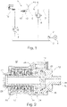
- a hydraulic pump 2 driven by an electric motor 1 takes over oil from a tank 3 as hydraulic fluid and feeds it via a check valve 4 to a pressure line 5 of a hydraulic circuit 6 .
- a pressure-limiting valve 8 branches off from a feed line 7 in front of the check valve 4 and opens into the tank 3 on the outlet side. With regard to its opening pressure, the pressure-limiting valve 8 is set to the defined maximum pressure.
- the pressure line 5 leads to a control valve 9, which adjusts the pressure in the pressure line 5 of the hydraulic circuit 6, acting as a high-pressure valve.
- the control valve 9 is also connected to the tank 3 on the outlet side. The control valve 9 can be adjusted with regard to the maximum pressure threshold above which excess pressure is discharged into the tank 3 .
- a brake caliper 10 which can be actuated by the pressure prevailing in the pressure line.
- the pressure line 5 is monitored by a pressure transmitter 11 .
- a spring-loaded damping element 12 is also connected to the pressure line 5 of the hydraulic circuit 6 in order to compensate for leakage in the area of the pressure line 5 of the hydraulic circuit 6 for intermediate buffering of a small oil volume of at most 1 cm 3 .
- the spring strength is dimensioned such that the leakage compensation oil volume between a Switch-on pressure and switch-off pressure of the engine 1 for the hydraulic pump 2 is buffered.
- the plate spring assembly 13 of the damping element 12 is housed in a damping element housing 14 in such a way that it is supported on the one hand on the bottom side of the damping element housing 14 and on the other hand comes to rest against a piston 15 housed in the damping element housing 14 in a dynamically sealed, axially movable manner.
- the piston acts on the oil pressure.
- the piston 15 is guided in a dynamically sealed manner within a cylinder head 16 so that it can move axially.
- the cylinder head 16 is screwed into the pot-shaped damping element housing 14 .
- the screw-in depth of the cylinder head 16 is variable, so that the prestressing of the plate spring assembly 13 can be adjusted in this way.
- a releasable securing element 17 designed as a countersunk screw is screwed into the damping element housing 14 axis-parallel to its longitudinal extension.
- the screw head of the securing element 17 comes to rest against the edge region of the cylinder head 16 in a clamping manner.
- the cylinder head 16 also has a coaxial connection bore 18, via which a connection to the pressure line 5 of the hydraulic circuit 6 takes place.
- a threaded pin 19 is formed on the cylinder head 16, with which a detachable connection to a - not shown here - corresponding threaded connection opening on the pressure line 5 can be produced.
- the piston 15 has a rear guide shaft section 20 .
- the guide shaft section 20 runs through a central recess in the plate spring assembly 13 . There is a loose fit between this recess of the plate spring assembly 13 and the guide shaft section 20 .
- the guide shaft section 20 opens into a guide blind hole 21 in the bottom area of the Pot-shaped damping element housing 14 a. The piston 15 is thus guided on the one hand by the cylinder head 16 and on the other hand by the bottom area of the pot-shaped damping element housing 14.
- the piston-cylinder arrangement of the damping element can also be designed differently, for example without using a variable screw-in depth of the cylinder head for setting the preload of the spring strength. It is also possible that the cylinder head is not screwed into the damping element housing but is screwed onto its outer wall.
- the spring-loaded damping element 12 is also equipped with various sealing rings, including a dynamic piston sealing ring 22 and a static housing sealing ring 23. Furthermore, a stop ring 24 is used to limit the stroke in the cylinder head 16 and the bottom guide of the guide shaft section 20 of the piston 15 is provided with a sliding guide ring 25.
Landscapes
- Engineering & Computer Science (AREA)
- Transportation (AREA)
- Mechanical Engineering (AREA)
- Braking Arrangements (AREA)
- Regulating Braking Force (AREA)
- Braking Systems And Boosters (AREA)
- Fluid-Pressure Circuits (AREA)
Claims (10)
- Système de freinage hydraulique passif sans stockage, dans lequel une pompe (2) hydraulique, entraînée par un moteur (1), produit une pression d'huile qui, par un clapet (4) antiretour, alimente un conduit (5) de pression d'un circuit (6) hydraulique, qui soumet à une pression d'alimentation hydraulique au moins étrier (10) de frein, qui y est raccordé,
caractérisé en ce qu'au conduit (5) de pression du circuit (6) hydraulique est raccordé un élément (12) d'amortissement soumis à une force de ressort pour le tamponnage intermédiaire d'un volume d'huile de compensation de fuite. - Système de freinage hydraulique passif sans stockage suivant la revendication 1,
caractérisé en ce que la force de ressort de l'élément (6) d'amortissement et/ou le volume associé à celui-ci est réglable et est tel que le volume d'huile de compensation de fuite est tamponné intermédiairement, entre une pression de remise en circuit et une pression d'arrêt du moteur (1) de la pompe (2) hydraulique. - Système de freinage hydraulique passif sans stockage suivant la revendication 1 ou 2,
caractérisé en ce que l'élément (12) d'amortissement soumis à l'action d'un ressort est constitué réglable en ce qui concerne la force de ressort pouvant être appliquée au circuit (6) hydraulique. - Système de freinage hydraulique passif sans stockage suivant la revendication 1 à 3,
caractérisé en ce qu'il est prévu, pour l'application de la force de ressort de l'élément (12) d'amortissement, un paquet (13) de ressorts à disque, qui vient en contact, du côté opposé à la pression hydraulique, avec un piston (15), logé de manière mobile, avec étanchéité dynamiquement, axialement dans un boîtier (14) de l'élément d'amortissement. - Système de freinage hydraulique passif sans stockage suivant la revendication 4,
caractérisé en ce qu'une tête (16) cylindrique est vissée dans le boîtier (14) de l'élément d'amortissement en forme de pot et coopère, d'une manière étanche dynamiquement, avec le piston (15), la profondeur de vissage de la tête (16) cylindrique déterminant la force de ressort du paquet (13) de ressorts à disque. - Système de freinage hydraulique passif sans stockage suivant la revendication 5,
caractérisé en ce que la profondeur de vissage de la tête (16) cylindrique dans le boîtier (14) de l'élément d'amortissement est assurée au moyen d'un élément (17) d'arrêt amovible. - Système de freinage hydraulique passif sans stockage suivant la revendication 5,
caractérisé en ce que, dans la tête (16) cylindrique est prévu un trou (18) coaxial de raccordement, pour le raccordement au conduit (5) de pression du circuit (6) hydraulique. - Système de freinage hydraulique passif sans stockage suivant la revendication 4,
caractérisé en ce que le piston (15) a une partie (20) de fût de guidage vers l'arrière, qui passe dans un évidement central du paquet (13) de ressorts à disque, et qui est guidé, du côté de l'extrémité distale, dans un trou (21) de base de guidage dans la partie de fond du boîtier (14) en forme de pot de l'élément d'amortissement. - Système de freinage hydraulique passif sans stockage suivant l'une des revendications précédentes,
caractérisé en ce que l'espace cylindrique formé entre la tête (16) cylindrique et le piston (15) tamponne un volume d'huile de compensation de fuite compris entre 0,3 et 1 cm3, de préférence entre 0,4 à 0,8 cm3 d'huile. - Système de freinage hydraulique passif sans stockage suivant l'une des revendications précédentes,
caractérisé en ce que l'élément (12) d'amortissement soumis à l'action de ressort est intégré dans la partie de réservoir d'un appareil hydraulique sans stockage.
Applications Claiming Priority (2)
| Application Number | Priority Date | Filing Date | Title |
|---|---|---|---|
| DE102017117422.2A DE102017117422A1 (de) | 2017-08-01 | 2017-08-01 | Passives speicherloses hydraulisches Bremssystem |
| PCT/EP2018/070309 WO2019025284A1 (fr) | 2017-08-01 | 2018-07-26 | Système de freinage hydraulique passif sans stockage |
Publications (2)
| Publication Number | Publication Date |
|---|---|
| EP3661822A1 EP3661822A1 (fr) | 2020-06-10 |
| EP3661822B1 true EP3661822B1 (fr) | 2023-03-15 |
Family
ID=63047365
Family Applications (1)
| Application Number | Title | Priority Date | Filing Date |
|---|---|---|---|
| EP18746913.5A Active EP3661822B1 (fr) | 2017-08-01 | 2018-07-26 | Système de freinage hydraulique passif sans stockage |
Country Status (5)
| Country | Link |
|---|---|
| EP (1) | EP3661822B1 (fr) |
| CN (1) | CN110997432B (fr) |
| DE (1) | DE102017117422A1 (fr) |
| ES (1) | ES2946037T3 (fr) |
| WO (1) | WO2019025284A1 (fr) |
Family Cites Families (9)
| Publication number | Priority date | Publication date | Assignee | Title |
|---|---|---|---|---|
| DE3603079A1 (de) | 1986-02-01 | 1987-08-06 | Teves Gmbh Alfred | Hydraulische speicherlose schlupfgeregelte bremsanlage |
| DE19857378A1 (de) * | 1998-12-12 | 2000-06-21 | Lfk Gmbh | Hydraulischer Manipulator |
| DE10340972A1 (de) * | 2003-09-05 | 2005-03-24 | Robert Bosch Gmbh | Hydraulische Bremsanlage und Verfahren zu deren Steuerung |
| CN100372713C (zh) * | 2004-09-15 | 2008-03-05 | 株式会社日立制作所 | 制动控制系统 |
| JP5071264B2 (ja) * | 2008-06-19 | 2012-11-14 | トヨタ自動車株式会社 | アキュムレータ制御装置 |
| WO2012073353A1 (fr) * | 2010-12-01 | 2012-06-07 | トヨタ自動車株式会社 | Système de frein hydraulique |
| CN202480875U (zh) * | 2011-12-30 | 2012-10-10 | 长城汽车股份有限公司 | 汽车液控驻车机构 |
| CN102963345B (zh) * | 2012-12-04 | 2014-10-01 | 大连华锐重工集团股份有限公司 | 一种带速度补偿器的被动式液压制动器液压系统 |
| CN108137020B (zh) * | 2015-10-13 | 2021-07-16 | 罗伯特·博世有限公司 | 液压总成 |
-
2017
- 2017-08-01 DE DE102017117422.2A patent/DE102017117422A1/de not_active Ceased
-
2018
- 2018-07-26 CN CN201880050242.8A patent/CN110997432B/zh not_active Expired - Fee Related
- 2018-07-26 WO PCT/EP2018/070309 patent/WO2019025284A1/fr not_active Ceased
- 2018-07-26 EP EP18746913.5A patent/EP3661822B1/fr active Active
- 2018-07-26 ES ES18746913T patent/ES2946037T3/es active Active
Also Published As
| Publication number | Publication date |
|---|---|
| CN110997432A (zh) | 2020-04-10 |
| EP3661822A1 (fr) | 2020-06-10 |
| CN110997432B (zh) | 2023-03-28 |
| WO2019025284A1 (fr) | 2019-02-07 |
| ES2946037T3 (es) | 2023-07-12 |
| DE102017117422A1 (de) | 2019-02-07 |
Similar Documents
| Publication | Publication Date | Title |
|---|---|---|
| EP3145771B1 (fr) | Systeme d'actuation d'un frein de vehicule et methode d'actuation du frein | |
| DE10327411B4 (de) | Druckbegrenzungsventil sowie Kraftstoffsystem mit einem solchen Druckbegrenzungsventil | |
| DE102016222562A1 (de) | Pedalwegsimulator und Hydraulikblock mit einem Pedalwegsimulator | |
| DE102013200050A1 (de) | Überströmventil für eine Kraftstoffpumpe | |
| DE102014107112A1 (de) | Betätigungssystem für eine Fahrzeugbremse und Verfahren zum Betrieb des Betätigungssystems | |
| EP3380374A1 (fr) | Dispositif de freinage pour un système de freinage hydraulique de véhicule à moteur | |
| DE102016216491A1 (de) | Zugmittelspanneinheit für einen Zugmitteltrieb | |
| DE112022005113T5 (de) | Dämpfungsvorrichtung, Flüssigkeitsdruck-Steuereinheit und Bremssystem | |
| DE102017209618A1 (de) | Pedalwegsimulator für eine hydraulische Fremdkraft-Fahrzeugbremsanlage | |
| DE4413190B4 (de) | Druckbegrenzungsventil und Verfahren zum Einstellen eines Öffnungsdruckes an dem Druckbegrenzungsventil | |
| DE102009000577B4 (de) | Kfz-Bremssystem mit einem verbesserten Anlaufverhalten einer Rückförderpumpe | |
| WO2016155712A1 (fr) | Tendeur hydraulique de moyen de traction muni d'un régulateur de pression | |
| WO2015177207A1 (fr) | Système d'actionnement d'un frein de véhicule et procédé pour faire fonctionner le système d'actionnement | |
| EP3661822B1 (fr) | Système de freinage hydraulique passif sans stockage | |
| DE10320800A1 (de) | Hydraulische Fahrzeugbremse | |
| DE102010038994A1 (de) | Hochdruckpumpe | |
| DE102005045937A1 (de) | Kolbenpumpe für eine Schlupfregelung aufweisende Fahrzeugbremsanlage | |
| WO2010000508A1 (fr) | Pompe à pistons multiples | |
| EP3165333B1 (fr) | Unité hydraulique pour un outil hydraulique mobil | |
| DE19949525B4 (de) | Druckübersetzer für ein Kraftstoffeinspritzsystem für Brennkraftmaschinen mit hydraulisch unterstützter Wiederbefüllung | |
| EP1413756A1 (fr) | Pompe à combustible | |
| EP2423536B1 (fr) | Dispositif de serrage hydraulique doté d'un stockage temporaire | |
| WO2004020864A1 (fr) | Etrier de frein | |
| DE102005052692B3 (de) | Elektrohydraulische Überwachungseinrichtung | |
| EP1378415A1 (fr) | Dispositif de frein à ressort |
Legal Events
| Date | Code | Title | Description |
|---|---|---|---|
| STAA | Information on the status of an ep patent application or granted ep patent |
Free format text: STATUS: UNKNOWN |
|
| STAA | Information on the status of an ep patent application or granted ep patent |
Free format text: STATUS: THE INTERNATIONAL PUBLICATION HAS BEEN MADE |
|
| PUAI | Public reference made under article 153(3) epc to a published international application that has entered the european phase |
Free format text: ORIGINAL CODE: 0009012 |
|
| STAA | Information on the status of an ep patent application or granted ep patent |
Free format text: STATUS: REQUEST FOR EXAMINATION WAS MADE |
|
| 17P | Request for examination filed |
Effective date: 20200302 |
|
| AK | Designated contracting states |
Kind code of ref document: A1 Designated state(s): AL AT BE BG CH CY CZ DE DK EE ES FI FR GB GR HR HU IE IS IT LI LT LU LV MC MK MT NL NO PL PT RO RS SE SI SK SM TR |
|
| AX | Request for extension of the european patent |
Extension state: BA ME |
|
| RIN1 | Information on inventor provided before grant (corrected) |
Inventor name: LI, YUZHI Inventor name: NIES, EDUARD Inventor name: ELWISCHGER, FABIAN |
|
| DAV | Request for validation of the european patent (deleted) | ||
| DAX | Request for extension of the european patent (deleted) | ||
| GRAP | Despatch of communication of intention to grant a patent |
Free format text: ORIGINAL CODE: EPIDOSNIGR1 |
|
| STAA | Information on the status of an ep patent application or granted ep patent |
Free format text: STATUS: GRANT OF PATENT IS INTENDED |
|
| INTG | Intention to grant announced |
Effective date: 20221021 |
|
| GRAS | Grant fee paid |
Free format text: ORIGINAL CODE: EPIDOSNIGR3 |
|
| GRAA | (expected) grant |
Free format text: ORIGINAL CODE: 0009210 |
|
| STAA | Information on the status of an ep patent application or granted ep patent |
Free format text: STATUS: THE PATENT HAS BEEN GRANTED |
|
| AK | Designated contracting states |
Kind code of ref document: B1 Designated state(s): AL AT BE BG CH CY CZ DE DK EE ES FI FR GB GR HR HU IE IS IT LI LT LU LV MC MK MT NL NO PL PT RO RS SE SI SK SM TR |
|
| REG | Reference to a national code |
Ref country code: CH Ref legal event code: EP Ref country code: GB Ref legal event code: FG4D Free format text: NOT ENGLISH |
|
| REG | Reference to a national code |
Ref country code: DE Ref legal event code: R096 Ref document number: 502018011781 Country of ref document: DE |
|
| REG | Reference to a national code |
Ref country code: IE Ref legal event code: FG4D Free format text: LANGUAGE OF EP DOCUMENT: GERMAN |
|
| REG | Reference to a national code |
Ref country code: AT Ref legal event code: REF Ref document number: 1553850 Country of ref document: AT Kind code of ref document: T Effective date: 20230415 |
|
| REG | Reference to a national code |
Ref country code: LT Ref legal event code: MG9D |
|
| REG | Reference to a national code |
Ref country code: ES Ref legal event code: FG2A Ref document number: 2946037 Country of ref document: ES Kind code of ref document: T3 Effective date: 20230712 |
|
| REG | Reference to a national code |
Ref country code: NL Ref legal event code: MP Effective date: 20230315 |
|
| PG25 | Lapsed in a contracting state [announced via postgrant information from national office to epo] |
Ref country code: RS Free format text: LAPSE BECAUSE OF FAILURE TO SUBMIT A TRANSLATION OF THE DESCRIPTION OR TO PAY THE FEE WITHIN THE PRESCRIBED TIME-LIMIT Effective date: 20230315 Ref country code: NO Free format text: LAPSE BECAUSE OF FAILURE TO SUBMIT A TRANSLATION OF THE DESCRIPTION OR TO PAY THE FEE WITHIN THE PRESCRIBED TIME-LIMIT Effective date: 20230615 Ref country code: LV Free format text: LAPSE BECAUSE OF FAILURE TO SUBMIT A TRANSLATION OF THE DESCRIPTION OR TO PAY THE FEE WITHIN THE PRESCRIBED TIME-LIMIT Effective date: 20230315 Ref country code: LT Free format text: LAPSE BECAUSE OF FAILURE TO SUBMIT A TRANSLATION OF THE DESCRIPTION OR TO PAY THE FEE WITHIN THE PRESCRIBED TIME-LIMIT Effective date: 20230315 Ref country code: HR Free format text: LAPSE BECAUSE OF FAILURE TO SUBMIT A TRANSLATION OF THE DESCRIPTION OR TO PAY THE FEE WITHIN THE PRESCRIBED TIME-LIMIT Effective date: 20230315 |
|
| PG25 | Lapsed in a contracting state [announced via postgrant information from national office to epo] |
Ref country code: SE Free format text: LAPSE BECAUSE OF FAILURE TO SUBMIT A TRANSLATION OF THE DESCRIPTION OR TO PAY THE FEE WITHIN THE PRESCRIBED TIME-LIMIT Effective date: 20230315 Ref country code: NL Free format text: LAPSE BECAUSE OF FAILURE TO SUBMIT A TRANSLATION OF THE DESCRIPTION OR TO PAY THE FEE WITHIN THE PRESCRIBED TIME-LIMIT Effective date: 20230315 Ref country code: GR Free format text: LAPSE BECAUSE OF FAILURE TO SUBMIT A TRANSLATION OF THE DESCRIPTION OR TO PAY THE FEE WITHIN THE PRESCRIBED TIME-LIMIT Effective date: 20230616 Ref country code: FI Free format text: LAPSE BECAUSE OF FAILURE TO SUBMIT A TRANSLATION OF THE DESCRIPTION OR TO PAY THE FEE WITHIN THE PRESCRIBED TIME-LIMIT Effective date: 20230315 |
|
| PG25 | Lapsed in a contracting state [announced via postgrant information from national office to epo] |
Ref country code: SM Free format text: LAPSE BECAUSE OF FAILURE TO SUBMIT A TRANSLATION OF THE DESCRIPTION OR TO PAY THE FEE WITHIN THE PRESCRIBED TIME-LIMIT Effective date: 20230315 Ref country code: RO Free format text: LAPSE BECAUSE OF FAILURE TO SUBMIT A TRANSLATION OF THE DESCRIPTION OR TO PAY THE FEE WITHIN THE PRESCRIBED TIME-LIMIT Effective date: 20230315 Ref country code: PT Free format text: LAPSE BECAUSE OF FAILURE TO SUBMIT A TRANSLATION OF THE DESCRIPTION OR TO PAY THE FEE WITHIN THE PRESCRIBED TIME-LIMIT Effective date: 20230717 Ref country code: EE Free format text: LAPSE BECAUSE OF FAILURE TO SUBMIT A TRANSLATION OF THE DESCRIPTION OR TO PAY THE FEE WITHIN THE PRESCRIBED TIME-LIMIT Effective date: 20230315 Ref country code: CZ Free format text: LAPSE BECAUSE OF FAILURE TO SUBMIT A TRANSLATION OF THE DESCRIPTION OR TO PAY THE FEE WITHIN THE PRESCRIBED TIME-LIMIT Effective date: 20230315 |
|
| PG25 | Lapsed in a contracting state [announced via postgrant information from national office to epo] |
Ref country code: SK Free format text: LAPSE BECAUSE OF FAILURE TO SUBMIT A TRANSLATION OF THE DESCRIPTION OR TO PAY THE FEE WITHIN THE PRESCRIBED TIME-LIMIT Effective date: 20230315 Ref country code: PL Free format text: LAPSE BECAUSE OF FAILURE TO SUBMIT A TRANSLATION OF THE DESCRIPTION OR TO PAY THE FEE WITHIN THE PRESCRIBED TIME-LIMIT Effective date: 20230315 Ref country code: IS Free format text: LAPSE BECAUSE OF FAILURE TO SUBMIT A TRANSLATION OF THE DESCRIPTION OR TO PAY THE FEE WITHIN THE PRESCRIBED TIME-LIMIT Effective date: 20230715 |
|
| REG | Reference to a national code |
Ref country code: DE Ref legal event code: R097 Ref document number: 502018011781 Country of ref document: DE |
|
| PLBE | No opposition filed within time limit |
Free format text: ORIGINAL CODE: 0009261 |
|
| STAA | Information on the status of an ep patent application or granted ep patent |
Free format text: STATUS: NO OPPOSITION FILED WITHIN TIME LIMIT |
|
| PG25 | Lapsed in a contracting state [announced via postgrant information from national office to epo] |
Ref country code: SI Free format text: LAPSE BECAUSE OF FAILURE TO SUBMIT A TRANSLATION OF THE DESCRIPTION OR TO PAY THE FEE WITHIN THE PRESCRIBED TIME-LIMIT Effective date: 20230315 Ref country code: DK Free format text: LAPSE BECAUSE OF FAILURE TO SUBMIT A TRANSLATION OF THE DESCRIPTION OR TO PAY THE FEE WITHIN THE PRESCRIBED TIME-LIMIT Effective date: 20230315 |
|
| 26N | No opposition filed |
Effective date: 20231218 |
|
| PG25 | Lapsed in a contracting state [announced via postgrant information from national office to epo] |
Ref country code: MC Free format text: LAPSE BECAUSE OF FAILURE TO SUBMIT A TRANSLATION OF THE DESCRIPTION OR TO PAY THE FEE WITHIN THE PRESCRIBED TIME-LIMIT Effective date: 20230315 |
|
| PG25 | Lapsed in a contracting state [announced via postgrant information from national office to epo] |
Ref country code: MC Free format text: LAPSE BECAUSE OF FAILURE TO SUBMIT A TRANSLATION OF THE DESCRIPTION OR TO PAY THE FEE WITHIN THE PRESCRIBED TIME-LIMIT Effective date: 20230315 |
|
| REG | Reference to a national code |
Ref country code: CH Ref legal event code: PL |
|
| REG | Reference to a national code |
Ref country code: BE Ref legal event code: MM Effective date: 20230731 |
|
| PG25 | Lapsed in a contracting state [announced via postgrant information from national office to epo] |
Ref country code: LU Free format text: LAPSE BECAUSE OF NON-PAYMENT OF DUE FEES Effective date: 20230726 |
|
| GBPC | Gb: european patent ceased through non-payment of renewal fee |
Effective date: 20230726 |
|
| PG25 | Lapsed in a contracting state [announced via postgrant information from national office to epo] |
Ref country code: LU Free format text: LAPSE BECAUSE OF NON-PAYMENT OF DUE FEES Effective date: 20230726 |
|
| REG | Reference to a national code |
Ref country code: IE Ref legal event code: MM4A |
|
| PG25 | Lapsed in a contracting state [announced via postgrant information from national office to epo] |
Ref country code: CH Free format text: LAPSE BECAUSE OF NON-PAYMENT OF DUE FEES Effective date: 20230731 Ref country code: GB Free format text: LAPSE BECAUSE OF NON-PAYMENT OF DUE FEES Effective date: 20230726 |
|
| PG25 | Lapsed in a contracting state [announced via postgrant information from national office to epo] |
Ref country code: IT Free format text: LAPSE BECAUSE OF FAILURE TO SUBMIT A TRANSLATION OF THE DESCRIPTION OR TO PAY THE FEE WITHIN THE PRESCRIBED TIME-LIMIT Effective date: 20230315 Ref country code: BE Free format text: LAPSE BECAUSE OF NON-PAYMENT OF DUE FEES Effective date: 20230731 |
|
| PG25 | Lapsed in a contracting state [announced via postgrant information from national office to epo] |
Ref country code: IE Free format text: LAPSE BECAUSE OF NON-PAYMENT OF DUE FEES Effective date: 20230726 |
|
| PG25 | Lapsed in a contracting state [announced via postgrant information from national office to epo] |
Ref country code: IE Free format text: LAPSE BECAUSE OF NON-PAYMENT OF DUE FEES Effective date: 20230726 |
|
| PG25 | Lapsed in a contracting state [announced via postgrant information from national office to epo] |
Ref country code: BG Free format text: LAPSE BECAUSE OF FAILURE TO SUBMIT A TRANSLATION OF THE DESCRIPTION OR TO PAY THE FEE WITHIN THE PRESCRIBED TIME-LIMIT Effective date: 20230315 |
|
| PG25 | Lapsed in a contracting state [announced via postgrant information from national office to epo] |
Ref country code: BG Free format text: LAPSE BECAUSE OF FAILURE TO SUBMIT A TRANSLATION OF THE DESCRIPTION OR TO PAY THE FEE WITHIN THE PRESCRIBED TIME-LIMIT Effective date: 20230315 |
|
| PG25 | Lapsed in a contracting state [announced via postgrant information from national office to epo] |
Ref country code: CY Free format text: LAPSE BECAUSE OF FAILURE TO SUBMIT A TRANSLATION OF THE DESCRIPTION OR TO PAY THE FEE WITHIN THE PRESCRIBED TIME-LIMIT; INVALID AB INITIO Effective date: 20180726 |
|
| PG25 | Lapsed in a contracting state [announced via postgrant information from national office to epo] |
Ref country code: HU Free format text: LAPSE BECAUSE OF FAILURE TO SUBMIT A TRANSLATION OF THE DESCRIPTION OR TO PAY THE FEE WITHIN THE PRESCRIBED TIME-LIMIT; INVALID AB INITIO Effective date: 20180726 |
|
| PGFP | Annual fee paid to national office [announced via postgrant information from national office to epo] |
Ref country code: ES Payment date: 20250815 Year of fee payment: 8 |
|
| PGFP | Annual fee paid to national office [announced via postgrant information from national office to epo] |
Ref country code: DE Payment date: 20250724 Year of fee payment: 8 |
|
| PGFP | Annual fee paid to national office [announced via postgrant information from national office to epo] |
Ref country code: FR Payment date: 20250724 Year of fee payment: 8 Ref country code: AT Payment date: 20250718 Year of fee payment: 8 |
|
| PG25 | Lapsed in a contracting state [announced via postgrant information from national office to epo] |
Ref country code: TR Free format text: LAPSE BECAUSE OF FAILURE TO SUBMIT A TRANSLATION OF THE DESCRIPTION OR TO PAY THE FEE WITHIN THE PRESCRIBED TIME-LIMIT Effective date: 20230315 |