EP3661866B1 - Vorrichtung zur aufnahme und zum transport von lasten - Google Patents
Vorrichtung zur aufnahme und zum transport von lasten Download PDFInfo
- Publication number
- EP3661866B1 EP3661866B1 EP18749792.0A EP18749792A EP3661866B1 EP 3661866 B1 EP3661866 B1 EP 3661866B1 EP 18749792 A EP18749792 A EP 18749792A EP 3661866 B1 EP3661866 B1 EP 3661866B1
- Authority
- EP
- European Patent Office
- Prior art keywords
- profile
- guide
- guide profile
- drive
- load
- Prior art date
- Legal status (The legal status is an assumption and is not a legal conclusion. Google has not performed a legal analysis and makes no representation as to the accuracy of the status listed.)
- Active
Links
Images


Classifications
-
- B—PERFORMING OPERATIONS; TRANSPORTING
- B66—HOISTING; LIFTING; HAULING
- B66F—HOISTING, LIFTING, HAULING OR PUSHING, NOT OTHERWISE PROVIDED FOR, e.g. DEVICES WHICH APPLY A LIFTING OR PUSHING FORCE DIRECTLY TO THE SURFACE OF A LOAD
- B66F9/00—Devices for lifting or lowering bulky or heavy goods for loading or unloading purposes
- B66F9/06—Devices for lifting or lowering bulky or heavy goods for loading or unloading purposes movable, with their loads, on wheels or the like, e.g. fork-lift trucks
- B66F9/075—Constructional features or details
- B66F9/12—Platforms; Forks; Other load supporting or gripping members
- B66F9/14—Platforms; Forks; Other load supporting or gripping members laterally movable, e.g. swingable, for slewing or transverse movements
- B66F9/142—Movements of forks either individually or relative to each other
- B66F9/143—Movements of forks relative to each other - symmetric
Definitions
- the invention relates to a device and a system for receiving and transporting loads, which is or is to be attached to another device.
- This device can be a stationary or movable device, whereby the movable device can be, for example, a vertically movable lifting carriage of an industrial truck.
- Such devices for picking up loads can, for example, be integrated into an industrial truck or designed as an attachment that is attached or is to be attached to a device such as a forklift truck. They usually have two or more load-carrying elements that can move relative to one another and, for example, can have the form of two fork tines that can move relative to one another.
- This mobility of the fork tines is achieved by appropriately designed adjustment devices and enables users to adapt the fork tines to the width of an object to be picked up or to recesses in it into which the fork tines engage.
- the load-handling elements can not only be moved towards and away from each other, but also both can be moved parallel and simultaneously in the same direction in order to compensate for an inaccurate approach with the industrial truck without having to maneuver the entire vehicle.
- This sideshift movement is made possible by the same drive elements as the movement of load-handling elements towards and away from each other.
- the respective adjustment devices are operated by the operator of the industrial truck from the workplace without him having to get off.
- a device for transporting loads which comprises two load-bearing elements, each of which is attached to horizontally movable sliding arms which can be moved relative to one another by drive elements, wherein the sliding arms are mounted on at least one sliding guide body and can be moved along a sliding guide body by the drive elements.
- the load-bearing elements are additionally each attached to movable guide arms which are guided on a guide rail, wherein the sliding guide body and the guide rail are connected to one another by two connecting elements and spaced apart from one another.
- the drive elements are partially arranged inside the sliding guide body and the sliding arms are movably guided within the sliding guide body, wherein the sliding guide body has a longitudinal slot through which a connecting section of the sliding arm protrudes from the sliding guide body and is connected to a load-bearing element.
- the sliding guide body thus at least partially encompasses both the drive elements and the sliding arms, so that these are advantageously protected in a sliding guide body, which also serves to guide the sliding arms. Damage and failure of the industrial truck can thus be reduced and maintenance costs remain low.
- the device can be designed to be compact, thus ensuring a good view from the operator to the load-handling elements and being able to be manufactured inexpensively.
- a fork positioning arrangement for mounting on a lift truck comprises a first fork positioner and a second fork positioner, the fork positioners being connected to a fork frame.
- the first fork positioner is constructed essentially as a mirror image of the second fork positioner.
- Each fork positioner comprises a tube with an internal cavity in which a piston and a carrier are arranged, both of which are coupled to a rod. The piston and the carrier are both in sliding contact with the tube.
- Each fork positioner has a fork holder arranged outside the tube, the fork holder being coupled to the carrier through a slot in the tube.
- the part of the carrier coupled to the fork holder is located between a first carrier bushing and a second carrier bushing. Due to the fork frame, the fork positioning arrangement is quite large, reducing the free cross-section between the fork positioners and thus the visibility for an operator of an industrial truck to which the fork positioning arrangement is attached.
- the device comprises at least two load-bearing elements, each of which is attached to horizontally movable sliding arms, which can be moved relative to one another and as a side thrust parallel in the same direction horizontally in or against the x-direction by at least two drive elements, wherein the sliding arms are mounted on a common upper sliding guide and the load-bearing elements are guided on a common guide rail in the y-direction below the sliding guide, wherein the at least two drive elements for the horizontal movement of the load-bearing elements relative to one another are designed as movable sliding arms and the at least two drive elements are each connected to a connection head via a piston rod and for the parallel movement of the load-bearing elements in the same direction, the at least two drive elements are connected via a simultaneous drive of the connection heads be moved together horizontally in or against the x-direction.
- the fork unit comprises a frame engaging the lower and upper edges of a plate member mounted on the front end of a forklift truck and accommodating a plurality of forks, the frame being displaceable in a direction substantially parallel to the plate member by means of a hydraulic cylinder acting between the plate member and the frame, the frame having a pair of vertically spaced and transversely extending upper and lower support beams fixedly connected to one another by a pair of spaced vertical side members, the upper support beam of which is substantially inverted U-shaped so as to be displaceable on an axis fixed to the upper edge of the plate member, the forks each having a vertically extending leg portion substantially in the same plane as the frame and a horizontally extending tine portion, the lower ends of the leg portions being displaceable along the lower support beam of the frame, while the upper ends of the leg portions are behind a projection of the upper support beam so as to enable the forks to move back and forth along the lower support beam, and means are provided between the upper support beam and the upper ends of the
- the object of the invention is therefore to provide a device for receiving loads which improves the device known from the prior art in that standard load-bearing elements can be used at the same time and the free cross-section for the view of an operator of the industrial truck on which the device is mounted is maximized, the device being compact and having a low construction depth.
- a further object of the invention is to provide a system for receiving and transporting loads for installation on mobile or stationary devices.
- this object is achieved by a device having the features of independent claim 1.
- Advantageous further developments of the device arise from the subclaims 2-18.
- the further object is achieved by a system according to claim 19.
- An advantageous further development of the system arises from claim 20.
- a device according to the invention for picking up and transporting loads can be mounted on a movable or stationary device.
- a movable device can be, for example, an industrial truck such as a forklift truck.
- a stationary device can be, for example, a stationary lifting device.
- the device comprises at least one first guide profile, wherein at least two load-bearing elements can be mounted on the first guide profile, wherein the at least two load-bearing elements can be moved relative to one another or parallel to one another in the longitudinal direction of the first guide profile by at least one drive element each. The distance between the load-bearing elements can be changed by moving relative to one another.
- a movement parallel to one another represents a so-called side-shift movement, via which, for example, a forklift operator can pick up or put down a load without having to maneuver the forklift truck precisely, by being able to move the load-bearing elements to pick-up points of a load that correspond to the distance between the load-bearing elements but are not exactly at the positions of the load-bearing elements.
- the device according to the invention is characterized in that the first guide profile has a hollow profile and a drive element is at least partially integrated in the first guide profile inside the guide profile, wherein a drive plate is operatively connected to the drive element and the guide of the drive plate is also at least partially integrated and mounted in the guide profile, wherein the drive element and the guide of the drive plate are on one axis, wherein the first guide profile has a longitudinal slot through which the holder of the drive plate protrudes, wherein a load-bearing element can be operatively connected to a drive plate. Due to the position of the drive element inside the first guide profile, the drive elements are well protected against external influences.
- the load-bearing elements can be easily inserted into the drive plates, so that standard load-bearing elements such as standard fork tines can be used, which can nevertheless carry out lateral movements relative to one another or parallel to one another. Due to the integration of the guide and By storing the carrier plate in the first guide profile, the size of the device is minimized and the cross-section for the view of an operator of an industrial truck is maximized.
- the first guide profile forms the supporting structural element. In other words, the first guide profile carries the at least two load-bearing elements. A further supporting structure is not required, which means that the inventive device is extremely compact and has a low structural depth.
- the device has, in addition to the first guide profile, a second guide profile arranged essentially parallel to the first guide profile, wherein the guide profiles are connected to one another at a distance from one another via at least one connecting element arranged essentially perpendicular to the guide profiles.
- the at least one connecting element can form a frame construction with the guide profiles, whereby the device can be mounted as an attachment on, for example, a forklift truck.
- vertically arranged mast cheeks which are mounted directly in the lifting frame of the industrial truck, form two connecting elements and, together with the two guide profiles, a frame that stabilizes the device.
- the second guide profile can have a hollow profile just like the first guide profile, whereby a drive element can be at least partially integrated in the interior of the second guide profile, whereby a drive plate can also be operatively connected to this drive element and the guide of a drive plate can also be at least partially integrated and mounted in the second guide profile, whereby here too the drive element and the guide of the drive plate lie on one axis, whereby at least the second guide profile also has a longitudinal slot through which the holder of a drive plate protrudes.
- the second guide profile can also carry the load-bearing elements.
- each drive element can be operatively connected to a drive unit on the one hand and to a drive plate on the other.
- At least one drive element has a spindle, for example a ball screw.
- At least one drive element has a fluid cylinder, for example a hydraulic or pneumatic cylinder.
- the drive unit has a hydraulic motor.
- the drive unit has an electric motor.
- a drive unit drives one or two drive elements.
- the drive unit can be arranged centrally in a guide profile, for example in the first guide profile, and drive two drive elements that are arranged on both sides of the drive unit in the direction of the guide profile. This can be done via a gear or directly. If the drive unit and the two drive elements that are operatively connected to the two drive plates are arranged in just one guide profile, the second guide profile only serves to support and guide the load-bearing elements. This can be done directly or indirectly via the drive plates. However, it is also conceivable to be able to dispense with a second guide profile, for example by making the first guide profile larger and more stable.
- both guide profiles each have a drive element.
- Both guide profiles can have a drive unit. It is also conceivable that only one guide profile has a drive unit or that no guide profile has a drive unit.
- the drive of the carrier plates is possible via fluid cylinders with pistons and piston rods, whereby the fluid can be, for example, compressed air or hydraulic fluid, which is provided by a central system, for example the hydraulic unit of an industrial truck on which the device is mounted.
- a drive unit in the form of a hydraulic motor or an electric motor in combination with a rotatable element, for example a spindle is installed as the drive element.
- Ball screws or threaded spindles can be used, for example.
- a hydraulic motor or an electric motor is advantageous for driving a rotary drive element or for driving two rotary drive elements in parallel. If two rotary drive elements are connected to only one drive unit, the direction of movement of at least one drive element can be reversed by interposing a gear, in particular a switchable gear, between the drive unit and at least one drive element, while the second drive element continues to rotate in the same direction. This enables the drive plates to move in opposite directions towards or away from each other, as well as the drive plates to move in the same direction in the form of a side-shift movement.
- the interposition of a gear for the two types of movement of the drive plates in relation to each other is not necessary.
- the combination of different drive units is also conceivable.
- the combination of different drive elements for example a spindle and a linear cylinder, for example a fluid cylinder in the form of a pneumatic or hydraulic cylinder, is also conceivable.
- An advantageous embodiment of the device is characterized in that the at least one first and the at least one second guide profile are connected to one another at a distance from one another via two connecting elements arranged essentially perpendicular to the guide profiles.
- the guide profiles and the connecting elements thus form a frame that maximizes the stability of the device.
- the longitudinal slots of the at least one first and the at least one second guide profile face each other. Due to the advantageous type of arrangement of the The first and second guide profiles have a maximum distance from each other due to the longitudinal slots, which further maximizes the free cross-section for the view of an operator of an industrial truck.
- the guide slots point forward, i.e. in the direction of the load-handling elements or in the direction of travel of the industrial truck.
- the two guide profiles are arranged essentially horizontally one above the other, so that the first guide profile is above the second guide profile and the longitudinal slot of the second guide profile is on the upper side of the second guide profile in the direction of the first guide profile, the longitudinal slot of the second guide profile being closed off by a protective element, for example a strip, that moves with the drive plate.
- the horizontal arrangement of the guide profiles one above the other is the usual arrangement for attaching the device to a forklift truck, for example.
- the longitudinal slot of the lower, second guide profile points upwards.
- the protective element which moves with the drive plate, closes this longitudinal slot at the top, so that the risk of contamination is minimized.
- the longitudinal slots have a length that corresponds to the maximum travel path of the drive plates.
- the drive elements have fluid-operated cylinders, each with a cylinder housing and a piston rod, with fastening means and guide means for the respective drive plate being at least partially integrated into the respective cylinder housing.
- Pressurized hydraulic oil is usually provided to a forklift, so it is advantageous to design the drive elements as hydraulic cylinders.
- connection head By integrating the fastening and guide means for the carrier plates into the cylinder housing, components are saved and the size is further minimized, which further maximizes the free cross-section for the view of an industrial truck operator. Another advantage is that the connections to the hydraulic cylinder are located directly next to each other via a connection head, which minimizes the effort required for the hydraulic connection.
- Pneumatic cylinders can also be used as drive elements.
- the invention also includes other drive elements, such as electrical drive elements.
- the guide profiles have a substantially rectangular outer cross-section with a substantially round cavity aligned in the axial direction of the respective guide profile.
- the substantially rectangular outer cross-section increases the stability of the guide profile and facilitates the installation of the load-bearing elements.
- the substantially round cavity facilitates the installation of fluid-operated cylinders, which usually have a substantially round outer cross-section.
- the cavity can also have a different cross-section, for example rectangular or oval.
- the cylinder is deep-drilled in the respective guide profile.
- the guide profiles can have a receiving profile for the hook suspension of the load-carrying devices.
- the load-carrying elements can be suspended from the upper guide profile, whereby they are carried by the upper guide profile and supported by the lower guide profile.
- the longitudinal slots are formed in such a way that they hold the drive plates in a vertical position and prevent them from turning away.
- the longitudinal slots can have guides for the drive plates, for example.
- This can be achieved, for example, by the holder of the respective drive plate being firmly connected to the respective cylinder housing as a cuboid-shaped elevation and protruding through the respective longitudinal slot of the respective guide profile, whereby the dimensions of the cuboid-shaped elevation and the width of the respective longitudinal slot are coordinated in such a way that the cuboid-shaped elevation can be supported perpendicular to the side thrust area on the side walls of the respective longitudinal slot. Wear elements can also be attached here.
- At least one guide profile encompasses more than half of the drive element arranged inside it. It has proven to be particularly advantageous if both guide profiles encompass more than half of the respective drive element. It has also proven to be particularly advantageous if the degree of encirclement of at least one guide profile is more than 75%.
- each drive plate is driven via the drive element in a guide profile and is additionally guided by the other guide profile, thereby increasing the stability of the overall construction.
- each carrier plate has a receiving profile for receiving the load-carrying device, wherein the receiving profile can be adapted to the width of the load-carrying device.
- the width of the receiving profile of the carrier plate can be adapted, for example, by designing the receiving profile as a U-profile, wherein the U-profile is divided with a fixed part and an exchangeable part, wherein the fixed part and the exchangeable part can be detachably connected to one another, for example screwed together, and exchangeable parts of different widths are provided.
- An inventive system for receiving and transporting loads for mounting on movable or stationary devices comprises at least one load-bearing element and the device according to the invention.
- the first guide profile has a receiving profile with a protruding strip on one of its outer sides, wherein the at least one load-bearing element can be suspended in the receiving profile by means of a suspension profile that is a mirror image of the receiving profile, wherein the suspension profile has a sliding piece that rests on the protruding strip of the receiving profile when the load-bearing element is suspended in the receiving profile.
- the sliding piece minimizes friction during the lateral adjustment of the load-bearing element, whereby less energy is required for the lateral adjustment of the load-bearing element and wear is minimized.
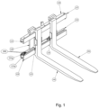
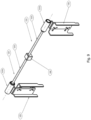
- Fig.1 shows a three-dimensional front view of an embodiment of the system 100 according to the invention with load-bearing elements 191, 192 in a narrow position.
- Two fork tines 191, 192 are suspended in a first, upper guide profile 120.
- the fork tines 191, 192 are supported on a second, lower guide profile 130.
- the first guide profile 120 and the second guide profile 130 are arranged parallel to one another and are connected to one another in a frame-like manner by two vertical connecting elements 140 at a distance from one another.
- the load-bearing elements 190, 191 are connected to drive plates 120, 135, which in turn can be moved horizontally relative to one another or parallel to one another in the longitudinal direction of the guide profiles 120, 130 via drive elements 121, 131.
- the two guide profiles 120, 130 each have a hollow profile, with a drive element 121, 131 being integrated into each guide profile 120, 130 inside the respective guide profile 120, 130.
- Each guide profile 125, 135 has a longitudinal slot 122, 132 through which the holder of the respective drive plate 125, 135 protrudes.
- the second longitudinal slot 132 in the second, lower guide profile 130 is directed upwards and is therefore susceptible to contamination.
- a drive element 121, 131 is integrated into the interior of the respective guide profile 120, 130.
- the driving plate 135 with a moving protective element 150 in the form of a strip closes off this second longitudinal slot 132 at the top and thus prevents contamination of the cavity in the second guide profile 130.
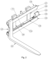
- Fig.2 shows a three-dimensional front view of an embodiment of the system 100 according to the invention with the second load-bearing element 192, which is suspended from the first guide profile and is in an external position, i.e. in a position that is as far out as possible from the center of the device 110.
- the second drive plate 135 is empty, so that the receiving profile 136 can be seen in the second drive plate 135.
- the receiving profile 136 consists of a U-shaped profile, the width of which is dimensioned such that both legs of the U can partially enclose the load-bearing elements 191, 192 used.
- the drive plates 125, 135 establish the connection of the sideshift drive to the fork tines 191, 192. Due to the shape of the receiving profile 126, 136, standard fork tines 191, 192 can be used.
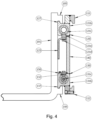
- Fig.3 shows a three-dimensional rear view of an embodiment of the system 100 according to the invention with fork tines 191, 192 in an external position.
- the guide means 121 e, 131 e can be seen.
- the guide means 121 e, 131 e have, on the one hand, the respective holder of the respective driving plate 126, 136 in the form of a cuboid-shaped elevation at the respective end of the respective cylinder housing 121 b, 131 b opposite the outlet side of the respective piston rod 121 c, 131 c, which protrude through the longitudinal slots 122, 132 in the direction of the respective driving plate 125, 135, wherein the longitudinal slots 122, 132 are designed such that they support and guide the cuboid-shaped elevations in a direction perpendicular to the direction of movement.
- the respective drive element 121, 131 lies on an axis with the guide of the respective drive plate 125, 135.
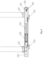
- Fig.4 shows a side section of a system 100 according to the invention.
- the device 110 has a first, upper suspension profile 111 and a second, lower suspension profile 112, with which the device 110 can be attached to a movable or stationary equipment, such as an industrial truck, by being hooked into a corresponding counter profile, for example a vertically movable lifting carriage of a forklift truck.
- the first hanging profile 111 is firmly connected to the device 100, for example by welding.
- the second hanging profile 112 is screwed to the device 100, so that the device 100 can first be hung from the counter profile of a lifting carriage by means of the first hanging profile 111 and then the second hanging profile 112 can be screwed on, so that the device is firmly connected to the lifting carriage in the direction of travel of the forklift truck and cannot tip over when pulling back, for example after a load has been set down.
- the figure shows the second fork tine 192, which is suspended with its suspension profiles in 195 on the first receiving profile 127 of the first guide profile 120 and the second receiving profile 137 of the second guide profile 130.
- the first driving plate 125 is also shown in section.
- the second driving plate 135 is connected with a screw as a fastening means 121 d via a cuboid-shaped elevation to the first drive element 121 of the first guide profile 120, the cuboid-shaped elevation with the first longitudinal slot 122 forming the first guide means 121 e.
- the second guide profile 130 can be seen, which has the second cylinder housing 131 b and the second piston rod 131 c.
- the second longitudinal slot 132 can also be seen, as well as the strip 150, which covers the second longitudinal slot 132 as a protective element.
- Both guide profiles 120, 130 surround the drive element 121, 131 arranged inside it by approximately 90%. By enclosing the drive element 121, 131 by the guide profile 120, 130, the drive element 121, 131 is protected in the guide profile 120, 130 and is held by it in such a way that it cannot bend or buckle even when great force is applied.
- Fig.5 shows a section from above through the second guide profile 130.
- the connection head 131 f is firmly connected to the frame and the second piston rod 131 c is connected to the connection head 131 f.
- the hydraulic oil runs through two channels through the second piston rod 131 c, once to the bottom side of the piston (load-bearing means move apart) and once to the rod side of the piston in the second cylinder housing 131 b (load-bearing means move towards each other).
- the second guide means 131 e is connected to the movable second cylinder housing 131 b. Sliding elements (not shown) are mounted between the second drive element 131 and the second guide profile 130.
- the first guide profile 120 is constructed in an analogous manner.
- Fig.6 shows a three-dimensional representation of a drive element 121,131 with a drive plate 125,135.
- the piston rod 121 c, 131 c can be seen, which is fixedly mounted in the guide profile 120, 130 (not shown), whereby the cylinder housing 121 b, 131 b is movable.
- the drive plate 125, 135 is attached to the cylinder housing 121 b, 131 b via the cuboid-shaped elevation as a holder using screws as fastening means 121 d, 131 d.
- the drive plate 125, 135 has a U-shaped receiving profile 126, 136.
- connection head 121 f, 131 f is firmly connected to the piston rod 121 d, 131 c and carries the hydraulic connections 200. Furthermore, the connection head 121 f, 131 f has a fastening means 121 g, 131 g in the form of a receiving bore for a bolt for fastening to the guide profile 120, 130.
- Fig.7 shows a three-dimensional representation of another embodiment of a drive element 121,131 with a drive plate 125,135.
- the driving plates 125, 135 are attached to a sliding arm 121 h, 131 h, which is driven by the respective piston rod 121 c, 131 c.
- Fig.8 shows a three-dimensional front view of an alternative embodiment of the system 100 according to the invention with the second load-bearing element 192, which is suspended from the first guide profile.
- the second carrier plate 135 is empty, so that the receiving profile 136 can be seen in the second carrier plate 135.
- the receiving profile 136 also consists in this embodiment of a U-shaped profile, the width of which is dimensioned such that that both legs of the U can partially enclose the load-bearing elements 191,192 used.
- the drive plates 125, 135 establish the connection of the sideshift drive with the forks 191, 192. Due to the shape of the support profile 126, 136, standard forks 191, 192 can be used.
- each drive plate 125, 135 is driven by the respective drive element 121, 131 in a guide profile 120, 130 and is additionally guided by the other guide profile 130, 120, with both the first longitudinal slot 122 and the second longitudinal slot 132 pointing forwards, i.e. in the direction of extension of the load-bearing elements 191, 192.
- the respective drive plates 125, 135 do not have to be guided by the respective other guide profile 120, 130, but can also be guided by just one guide profile 120, 130.
- an embodiment is also conceivable in which either both longitudinal slots 122, 132 point upwards, i.e. in opposite directions in the horizontal parts of the load-bearing elements 191, 192.
- a system 100 according to the invention is also conceivable in which the first longitudinal slot 122 points downwards in the direction of the second guide profile 130 and the second longitudinal slot 132 points upwards in the direction of the first guide profile 120.
- An arrangement of the guide slots 122, 132 which is the opposite of this is also conceivable.
- Fig.9 shows a three-dimensional representation of another embodiment of a drive element 121 with drive plates 125, 136.
- the drive elements shown are located in the Fig.9
- the first and the second drive element are in one plane and can therefore be installed in a guide profile (not shown in the figure).
- This drive unit 160 can be, for example, an electric or a fluid motor, for example a hydraulic motor.
- the drive unit 160 drives both the first drive element 121 and the second drive element 131 in rotation.
- Spindles for example recirculating ball or threaded spindles, are installed as drive elements 121, 131.
- Sliding arms 121 h, 131 h are moved via the drive elements 121, 131, on which the driving plates 125, 135 can be attached.
- a gear can be integrated in the drive unit (not shown in the figure), which can be switched and can reverse the direction of rotation of a drive element 121, 131, so that both a side-shift movement, in which the drive plates 125, 135 are moved parallel and in the same direction, and an opposite movement of the drive plates 125, 135, as is necessary for adjusting the distance between the load-bearing elements 191, 192 (not shown in the figure), is possible.
Landscapes
- Engineering & Computer Science (AREA)
- Transportation (AREA)
- Structural Engineering (AREA)
- Civil Engineering (AREA)
- Life Sciences & Earth Sciences (AREA)
- Geology (AREA)
- Mechanical Engineering (AREA)
- Forklifts And Lifting Vehicles (AREA)
Description
- Die Erfindung betrifft eine Vorrichtung und ein System zur Aufnahme und zum Transport von Lasten, welche an einer anderen Einrichtung befestigt oder zu befestigen ist. Bei dieser Einrichtung kann es sich um eine stationäre oder bewegliche Einrichtung handeln, wobei es sich bei der beweglichen Einrichtung beispielsweise um einen vertikal bewegbaren Hubschlitten eines Flurförderzeugs handeln kann.
- Derartige Vorrichtungen zur Aufnahme von Lasten können beispielsweise in ein Flurförderzeug integriert oder als Anbaugerät ausgebildet sein, das an einer Einrichtung wie einem Gabelstapler befestigt oder zu befestigen ist. Sie weisen meist zwei oder mehr zueinander bewegliche Lastaufnahmeelemente auf, die beispielsweise die Form zweier zueinander beweglicher Gabelzinken haben können. Diese Beweglichkeit der Gabelzinken wird durch entsprechend ausgebildete Verstellvorrichtungen erreicht und ermöglicht es den Anwendern, die Gabelzinken an die Breite eines aufzunehmenden Gegenstandes bzw. an darin befindliche Ausnehmungen, in welche die Gabelzinken eingreifen, anzupassen.
- In vielen Fällen können die Lastaufnahmeelemente nicht nur aufeinander zu und voneinander weg bewegt werden, sondern auch beide parallel und gleichzeitig in die gleichen Richtung bewegt werden, um eine ungenaue Anfahrt mit dem Flurförderzeug ohne Manövrieren mit dem gesamten Fahrzeug ausgleichen zu können. Diese Seitenschubbewegung wird von den gleichen Antriebselementen ermöglicht wie die Bewegung von Lastaufnahmeelementen aufeinander zu und voneinander weg. Die jeweiligen Verstellvorrichtungen werden dabei vom Bediener des Flurförderzeuges vom Arbeitsplatz aus betätigt, ohne dass er dazu absteigen muss.
- Da derartige lastaufnehmende Vorrichtungen meistens in relativ rauen Umgebungen intensiv im Einsatz sind, ist die Robustheit der Konstruktion ein wichtiges Anforderungskriterium. Die aufzunehmende Last kommt immer direkt mit der Vorrichtung in Berührung und ausstehende Teile der Last oder ein zu raues Aufnehmen der Last können zu Beschädigungen führen.
- Aus der deutschen Offenlegungsschrift
DE 10 2011 002 433 (A1 ) ist eine Vorrichtung zum Transport von Lasten bekannt, die zwei Lastaufnahmeelemente umfasst, die jeweils an horizontal beweglichen Gleitarmen angebracht sind, die durch Antriebselemente relativ zueinander bewegbar sind, wobei die Gleitarme an wenigstens einem Gleitführungskörper gelagert sind und durch die Antriebselemente entlang einem Gleitführungskörper bewegbar sind. Die Lastaufnahmeelemente sind zusätzlich jeweils an beweglichen Führungsarmen angebracht, die an einer Führungsschiene geführt sind, wobei der Gleitführungskörper und die Führungsschiene durch zwei Verbindungselemente miteinander verbunden und voneinander beabstandet sind. Die Antriebselemente sind teilweise im Innern des Gleitführungskörpers angeordnet und die Gleitarme sind beweglich innerhalb des Gleitführungskörpers geführt, wobei der Gleitführungskörper einen Längsschlitz aufweist, durch den ein Verbindungsabschnitt des Gleitarms aus dem Gleitführungskörper herausragt und mit einem Lastaufnahmeelement verbunden ist. Bei Betrieb der Vorrichtung liegt der größte Teil des jeweiligen Antriebselementes innerhalb des Gleitführungskörpers. Der Gleitführungskörper umgreift somit wenigstens teilweise sowohl die Antriebselemente als auch die Gleitarme, so dass diese vorteilhaft geschützt in einem Gleitführungskörper untergebracht sind, der gleichzeitig zur Führung der Gleitarme dient. Beschädigungen und ein Ausfall des Flurförderzeugs kann damit reduziert werden und die Wartungskosten bleiben somit gering. Gleichzeitig kann die Vorrichtung kompakt ausgeführt werden, um so auch eine gute Sicht vom Bediener zu den Lastaufnahmeelementen zu gewährleisten und kostengünstig hergestellt werden zu können. Nachteilig an dieser Konstruktion ist, dass zwei Gleitführungskörper übereinander liegen und den freien Querschnitt für die Durchsicht eines Bedieners eines Flurförderfahrzeugs durch die Vorrichtung trotz der Kompaktheit der Konstruktion dennoch einschränken. Darüber hinaus müssen die Lastaufnahmeelemente, d.h. die Gabelzinken, spezielle Aufnahmen für die Antriebselemente für die Seitenschubbewegung aufweisen. Mit anderen Worten können keine Standardgabelzinken an der Vorrichtung montiert werden. - Aus der internationalen Patentanmeldung
WO 2016 / 205 376 A1 ist eine Gabelpositionierungsanordnung zum Montieren an einem Hubwagen bekannt. Die Vorrichtung weist einen ersten Gabelpositionierer und einem zweiten Gabelpositionierer auf, wobei die Gabelpositionierer mit einem Gabelrahmen verbunden sind. Der erste Gabelpositionierer ist im wesentlichen spiegelbildlich zu dem zweiten Gabelpositionierer aufgebaut. Jeder Gabelpositionierer umfasst ein Rohr mit einem inneren Hohlraum, in dem ein Kolben und ein Träger angeordnet sind, die beide mit einer Stange gekoppelt sind. Der Kolben und der Träger sind beide in gleitendem Kontakt mit dem Rohr. Jeder Gabelpositionierer hat einen Gabelhalter, der außerhalb des Rohres angeordnet ist, wobei der Gabelhalter mit dem Träger durch einen Schlitz in dem Rohr gekoppelt ist. Der mit dem Gabelhalter gekoppelte Teil des Trägers befindet sich zwischen einer ersten Trägerbuchse und einer zweiten Trägerbuchse. Durch den Gabelrahmen baut die Gabelpositionierungsanordnung recht groß, wobei der freie Quesrschnitt zwischen den Gabelpositionierern und damit die Durchsichtmöglichkeit für einen Bediener eines Flurförderfahrzeugs, an dem die Gabelpositionierungsanordnung angebracht ist, verkleinert wird. - Aus der internationalen Patentanmeldung
WO 2014/122147 A1 ist eine Vorrichtung gemäß dem Oberbegriff des Anspruchs 1 bekannt. Die Vorrichtung umfasst wenigstens zwei Lastaufnahmeelemente, die jeweils an horizontal beweglichen Gleitarmen angebracht sind, die durch mindestens zwei Antriebselemente relativ zu einander und als Seitenschub parallel in gleicher Richtung horizontal in oder entgegen der x-Richtung bewegbar sind, wobei die Gleitarme an einer gemeinsamen oberen Gleitführung gelagert sind und die Lastaufnahmeelemente an einer gemeinsamen Führungsschiene in y-Richtung unterhalb der Gleitführung geführt sind, wobei die mindestens zwei Antriebselemente für die horizontale Bewegung der Lastaufnahmeelemente relativ zu einander als bewegliche Gleitarme ausgebildet sind und die mindestens zwei Antriebselemente über eine Kolbenstange mit jeweils einem Anschlusskopf verbunden sind und für die Parallelbewegung der Lastaufnahmeelemente in gleicher Richtung die mindestens zwei Antriebselemente über einen gleichzeitigen Antrieb der Anschlussköpfe gemeinsam in horizontaler Richtung in oder entgegen der x-Richtung bewegt werden. - Aus der europäischen Offenlegungsschrift
EP 0 314 207 A1 eine Gabeleinheit, die an dem am Stirnende eines Hubstaplers feststehenden Plattenglied angebracht und in Bezug auf diese Platte seitwärts verschoben werden kann und bei der die Position der Gabeln in Bezug auf einen Tragrahmen eingestellt werden kann. Die Gabeleinheit umfasst einen mit dem unteren und dem oberen Rand eines am Stirnende eines Gabelstaplers angebrachten Plattenglieds in Eingriff stehenden Rahmens und nimmt mehrere Gabeln aufnimmt, wobei der Rahmen in einer im Wesentlichen zum Plattenglied parallelen Richtung mittels eines zwischen dem Plattenglied und dem Rahmen wirkenden hydraulischen Zylinder verschieblich ist, wobei der Rahmen ein Paar vertikal beabstandete und sich quer erstreckende obere und untere, durch ein Paar beabstandeter vertikaler Seitenteile fest miteinander verbundene Stützträger aufweist, von denen der obere Stützträger im Wesentlichen eine umgekehrte U-Form hat, um auf einer am oberen Rand des Plattenglieds befestigten Achse verschieblich zu sein, wobei die Gabeln jeweils einen sich vertikal erstreckenden Schenkelabschnitt im Wesentlichen in derselben Ebene wie der Rahmen und einen sich horizontal erstreckenden Zinkenabschnitt haben und die unteren Enden der Schenkelabschnitte längs des unteren Stützträgers des Rahmens verschieblich sind, während die oberen Enden der Schenkelabschnitte zur Verhinderung einer Verschwenkung des Schenkelabschnitts um den unteren Stützträger hinter einem Vorsprung des oberen Stützträgers liegen, um so die Hin- und Herbewegung der Gabeln längs des unteren Stützträgers zu ermöglichen, und wobei zwischen dem oberen Stützträger und den oberen Enden der Schenkelabschnitte Mittel zur Verhinderung einer Verschiebung zwischen dem oberen Stützträger und den Gabeln vorgesehen sind. - Auch bei den beiden letzten aufgeführten Lehren aus dem Stand der Technik ist zumindest der freien Querschnitt für die Durchsicht eines Bedieners des Flurförderfahrzeugs, an dem die Vorrichtung montiert ist, eingeschränkt.
- Aufgabe der Erfindung ist es daher, eine Vorrichtung zur Aufnahme von Lasten bereitzustellen, welche die aus dem Stand der Technik bekannte Vorrichtung dahingehend verbessert, dass gleichzeitig Standardlastaufnahmeelemente benutzbar sind und der freie Querschnitt für die Durchsicht eines Bedieners des Flurförderfahrzeugs, an dem die Vorrichtung montiert ist, maximiert ist, wobei die Vorrichtung kompakt baut und eine geringe Konstruktionstiefe aufweist. Eine weitere Aufgabe der Erfindung ist es, ein System zur Aufnahme und zum Transport von Lasten für eine Montage an beweglichen oder stationären Einrichtungen anzugeben.
- Erfindungsgemäß wird diese Aufgabe durch eine Vorrichtung mit den Merkmalen des unabhängigen Anspruches 1 gelöst. Vorteilhafte Weiterbildungen der Vorrichtung ergeben sich aus den Unteransprüchen 2-18. Die weitere Aufgabe wird durch ein System gemäß Anspruch 19 gelöst. Eine vorteilhafte Weiterbildung des Systems ergibt sich aus Anspruch 20.
- Eine erfindungsgemäße Vorrichtung zur Aufnahme und zum Transport von Lasten ist an einer beweglichen oder stationären Einrichtung montiertbar. Dabei kann eine bewegliche Einrichtung beispielsweise ein Flurförderfahrzeug, wie ein Gabelstapler, sein. Eine stationäre Einrichtung kann beispielsweise eine stationäre Hubvorrichtung sein. Die Vorrichtung umfasst wenigstens ein erstes Führungsprofil, wobei mindestens zwei Lastaufnahmeelemente an dem ersten Führungsprofil montiertbar sind, wobei die mindestens zwei Lastaufnahmeelemente durch jeweils mindestens ein Antriebselement relativ zueinander oder parallel zueinander in Längsrichtung des ersten Führungsprofils bewegbar sind. Über eine Bewegung relativ zueinander kann der Abstand der Lastaufnahmeelemente voneinander verändert werden. Eine Bewegung parallel zueinander stellt eine sogenannte Seitenschubbewegung dar, über die beispielsweise ein Gabelstaplerbediener eine Last aufnehmen oder absetzen kann, ohne mit dem Gabelstapler exakt rangieren zu müssen, indem er Aufnahmepunkte einer Last, die zwar dem Abstand der Lastaufnahmeelemente entsprechen, aber nicht exakt an den Positionen der Lastaufnahmeelemente liegen, mit den Lastaufnahmeelementen trotzdem anfahren kann.
- Die erfindungsgemäße Vorrichtung zeichnet sich dadurch aus, dass das erste Führungsprofil ein Hohlprofil aufweist und in dem erstenFührungsprofil ein Antriebselement wenigstens teilweise im Inneren des Führungsprofils integriert ist, wobei eine Mitnahmeplatte mit dem Antriebselement wirkverbunden ist und in dem Führungsprofil auch die Führung der Mitnahmeplatte mindestens teilweise integriert und gelagert ist, wobei das Antriebselement und die Führung der Mitnahmeplatte auf einer Achse liegen, wobei das erste Führungsprofil einen Längsschlitz aufweist, durch den die Halterung der Mitnahmeplatte herausragt, wobei jeweils ein Lastaufnahmeelement mit einer Mitnahmeplatte wirkverbindbar ist. Durch die Lage des Antriebselements im Inneren des ersten Führungsprofils sind die Antriebselemente gegen äußere Einflüsse gut geschützt. Die Lastaufnahmeelemente können einfach in die Mitnahmeplatten eingesetzt werden, so das Standardlastaufnahmeelemente wie beispielsweise Standardgabelzinken verwendbar sind, die trotzdem seitliche Bewegungen relativ zueinander oder auch parallel zueinander ausführen können. Durch die Integration der Führung und Lagerung der Mitnahmeplatte in das erste Führungsprofil ist die Baugröße der Vorrichtung minimiert und der Querschnitt für den Durchblick eines Bedieners eines Flurförderfahrzeugs maximiert. Das erste Führungsprofil bildet dabei das tragende Konstruktionselement. Mit anderen Worten trägt das erste Führungsprofil die mindestens zwei Lastaufnahmeelemente. Eine weitere Tragekonstruktion ist nicht erforderlich, wodurch die erfinderische Vorrichtung überaus kompakt baut und eine geringe Konstruktionstiefe aufweist.
- In einer vorteilhaften Ausführungsform weist die Vorrichtung zusätzlich zu dem ersten Führungsprofil ein im Wesentlichen parallel zu dem ersten Führungsprofil angeordnetes zweites Führungsprofil auf, wobei die Führungsprofile über wenigstens ein im Wesentlichen senkrecht zu den Führungsprofilen angeordnetes Verbindungselement voneinander beabstandet miteinander verbunden sind. Das wenigstens eine Verbindungselement kann mit den Führungsprofilen eine Rahmenkonstruktion bilden, womit die Vorrichtung als Anbaugerät auswechselbar an z.B. einem Gabelstapler montiert werden kann. In einer anderen Ausführungsform bilden vertikal angeordnete Mastwangen, die direkt in dem Hubgerüst des Flurförderzeuges gelagert sind, zwei Verbindungslemente und gemeinsam mit den beiden Führungsprofilen einen die Vorrichtung stabilisierenden Rahmen. Das zweite Führungsprofil kann ebenso wie das erste Führungsprofil ein Hohlprofil aufweisen, wobei ein Antriebselement wenigstens teilweise im Inneren auch des zweiten Führungsprofils integriert sein kann, wobei auch mit diesem Antriebselement eine Mitnahmeplatte wirkverbunden sein und in auch dem zweiten Führungsprofil die Führung einer Mitnahmeplatte mindestens teilweise integriert und gelagert sein kann, wobei auch hier das Antriebselement und die Führung der Mitnahmeplatte auf einer Achse liegen, wobei zumindest auch das zweite Führungsprofil einen Längsschlitz aufweist, durch den die Halterung einer Mitnahmeplatte herausragt. Das zweite Führungsprofil kann dabei die Lastaufnahmeelemente mit tragen.
- Es hat sich als vorteilhaft erwiesen, wenn jedes Antriebselement einerseits mit einer Antriebseinheit und andererseits mit einer Mitnahmeplatte wirkverbindbar ist.
- In einer vorteilhaften Ausführungsform weist mindestens ein Antriebselement eine Spindel, beispielsweise eine Kugelumlaufspindel, auf.
- In einer weiteren vorteilhaften Ausführungsform weist mindestens ein Antriebselement einen Fluidzylinder, beispielsweise einen Hydraulik- oder einen Pneumatikzylinder, auf.
- In einer weiteren vorteilhaften Ausführungsform weist die Antriebseinheit einen Hydromotor auf.
- In einer weiteren vorteilhaften Ausführungsform weist die Antriebseinheit einen Elektromotor auf.
- Eine Antriebseinheit treibt eine oder zwei Antriebselemente an. Beispielsweise kann die Antriebseinheit mittig in einem Führungsprofil, beispielsweise in dem ersten Führungsprofil, angeordnet sein und zwei Antriebselemente, die zu beiden Seiten der Antriebseinheit in Richtung des Führungsprofil angeordnet sind, antreiben. Dies kann über ein Getriebe oder auch direkt erfolgen. Sind die Antriebseinheit und die beiden Antriebselemente, die mit den beiden Mitnahmeplatten wirkverbunden sind, in nur einem Führungsprofil angeordnet, so dient das zweite Führungsprofil nur zur Stützung und Führung der Lastaufnahmelemente. Dies kann direkt oder auch indirekt über die Mitnahmepaltten geschehen. Es ist aber auch denkbar, beisspielsweise durch eine größere und stabilere Ausgestaltung des ersten Führungsprofils auf ein zweites Führungsprofil verzichten zu können.
- In einer alternativen Ausführungsform weisen beide Führunsprofile jeweils ein Antriebselement auf. Dabei können beide Führungsprofile eine Antriebseinheit aufweisen. Ebenso denkbar ist, dass nur ein Führungsprofil eine Antriebseinheit aufweist oder auch auch kein Führungsprofil eine Antriebseinheit aufweist. In diesem Fall ist der Antrieb der Mitnahmeplatten über Fluidzylinder mit Kolben und Kolbenstangen möglich, wobei als Fluid beispielsweise Druckluft oder Hydraulikflüssigkeit denkbar ist, die von einem zentralen System, beispielsweise dem Hydraulikaggregat eines Flurförderfahrzeugs, an dem die Vorrichtung montiert ist, zur Verfügung gestellt wird.
- Vorzugsweise wird eine Antriebseinheit in Form eines Hydromotors oder eines Elektromotors in Kombination mit einem rotierbaren Element, beispielsweise einer Spindel, als Antriebselement verbaut. Dabei können beispielsweise Kugelumlaufspindeln oder Gewindespindeln zum Einsatz kommen. Ein Hydromotor oder auch ein Elektromotor ist vorteilhaft für den Antrieb eines rotatorisch bewegbaren Antriebselements oder auch für den parallelen Antrieb zweier rotatorisch bewegbarer Antriebslemente einsetzbar. Sind zwei rotatorisch bewegbare Antriebselelente mit nur einer Antriebseinheit verbunden, kann über die Zwischenschaltung eines Getriebes, insbesondree eines schaltbaren Getriebes, zwischen die Antriebseinheit und zumindest einem Antriebselement dessen Bewegungsrichtung umgekehrt werden, während das zweite Antriebselement in gleicher Richtung weiter rotiert. Dadurch ist eine gegenläufige Bewegung der Mitnahmeplatten zueinander beziehungsweise auseinander ebenso wie die gleichsinnige Bewegung der Mitnahmeplatten in Form einer Seitenschubbewegung möglich.
- Werden zwei Antriebseinheiten verbaut, so kann auf die Zwischenschaltung eines Getriebes für die beiden Bewegungsarten der Mitnahmeplatten in Relation zueinander verzichtet werden. Bei einer solchen Ausführungsform ist auch die Kombination von unterschiedlichen Antriebseinheiten denkbar. Ebenso ist die Kombination unterschiedlicher Antriebselemente, beispielsweise einer Spindel und eines Linearzylinders, beispielsweise eines Fluidzylinders in Form eines Pneumatik- oder eines Hydraulikzylinders, vorstellbar.
- Eine vorteilhafte Ausführungsform der Vorrichtung ist dadurch gekennzeichnet, dass das wenigstens eine erste und das wenigstens eine zweite Führungsprofil über zwei im Wesentlichen zu den Führungsprofilen senkrecht angeordnete Verbindungselemente voneinander beabstanded miteinander verbunden sind. Damit bilden die Führungsprofile mit den Verbindungselementen einen Rahmen, der die Stabilität der Vorrichtung maximiert.
- In einer weiteren vorteilhaften Ausführungsform der Vorrichtung weisen die Längsschlitze des wenigstens einen ersten und des wenigstens einen zweiten Führungsprofils zueinander hin. Durch die vorteilhafte Art der Anordnung der Längsschlitze zueinander weisen das erste und das zweite Führungsprofil einen maximalen Abstand zueinander auf, was den freien Querschnitt für den Durchblick eines Bedieners eines Flurförderfahrzeugs weiter maximiert.
- In einer alterntaiven Ausführungsform weisen die Führungsschlitze nach vorne, d.h. in Richtung der Lastaufnahmeelemente beziehungsweise in Fahrtrichtung des Flurförderfahrzeugs.
- Es hat sich als vorteilhaft erwiesen, wenn die beiden Führungsprofile im Wesentlichen horizontal übereinander angeordnet sind, sodass sich das erste Führungsprofil oberhalb des zweiten Führungsprofils und sich der Längsschlitz des zweiten Führungsprofils an der Oberseite des zweiten Führungsprofils in Richtung des ersten Führungsprofils befindet, wobei der Längsschlitz des zweiten Führungsprofils über ein mit der Mitnahmeplatte mitbewegtes Schutzelement, zum Beispiel eine Leiste, abgeschlossen wird. Die horizontale Anordnung der Führungsprofile übereinander ist die übliche Anordnung für den Anbau der Vorrichtung beispielsweise an einen Gabelstapler. Bei dieser Anordnung weist der Längsschlitz des unteren, zweiten Führungsprofils nach oben. Durch das mit der Mitnahmeplatte mit bewegte Schutzelement wird dieser Längsschlitz nach oben geschlossen, so dass die Verschmutzungsgefahr minimiert ist. Die Längsschlitze weisen eine dem maximalen Verfahrweg der Mitnahmeplatten entsprechende Länge auf.
- Weiterhin hat es sich als vorteilhaft erwiesen, wenn die Antriebselemente fluidbetriebene Zylinder mit jeweils einem Zylindergehäuse und einer Kolbenstange aufweisen, wobei Befestigungsmittel und Führungsmittel für die jeweilige Mitnahmeplatte in das jeweilige Zylindergehäuse zumindest teilweise integriert sind. Üblicherweise wird an einen Gabelstapler druckbeaufschlagtes Hydrauliköl zur Verfügung gestellt, sodass es vorteilhaft ist, die Antriebselemente als Hydraulikzylinder auszuführen.
- Es hat sich als vorteilhaft erwiesen, wenn Zylindergehäuse und Führung der jeweiligen Mitnahmeplatte einteilig ausgeführt sind. Dabei wird das Hydrauliköl wdurch einen Anschlußkopf durch zwei Kanäle in der mit dem Anschlußkopf verbundenen Kolbenstange zum Zylindergehäuse geführt.
- Durch die Integration der Befestigungs- und Führungsmittel für die Mitnahmeplatten in das Zylindergehäuse werden Bauteile eingespart und die Baugröße weiter minimiert, wodurch der freie Querschnitt für den Durchblick eines Flurförderfahrzeugs Bedieners weiter maximiert wird. Ein weiterer Vorteil ist, dass die Anschlüsse zum Hydraulikzylinder über einen Anschlußkopf direkt neben einander liegen, was den Aufwand für den hydraulischen Anschluß minimiert.
- Ebenso sind auch Pneumatikzylinder als Antriebselement vorstellbar. Die Erfindung umfasst aber auch andere Antriebselemente, wie besispielsweise elektrische Antriebselemente.
- In einer weiteren vorteilhaften Ausführungsform weisen die Führungsprofile einen im Wesentlichen rechteckigen Außenquerschnitt mit einem in Achsrichtung des jeweiligen Führungsprofils ausgerichteten im Wesentlichen runden Hohlraum auf. Der im Wesentlichen rechteckige Außenquerschnitt erhöht die Stabilität des Führungsprofils und erleichtert den Anbau der Lastaufnahmeelemente. Der im Wesentlichen rund ausgeführte Hohlraum erleichtert die Montage fluidbetriebener Zylinder, die üblicherweise einen im Wesentlichen runden äußeren Querschnitt aufweisen. In einer alternativen Ausführungsform aknn der Hohlraum auch einen anderen, beispielsweise rechteckingen oder ovalen, Querschnitt aufweisen.
- In einer allternativen Ausführungsform ist der Zylinder in dem jeweiligen Führungsprofil tiefgebohrt.
- Die Führungsprofile können ein Aufnahmeprofil für die Hakenaufhängung der Lastaufnahmemittel aufweisen. Die Lastaufnahmelelemente können an dem oberen Führungsprofil eingehängt werden, wobei sie von dem oberen Führungsprofil getragen und von dem unteren Fürhungsprofil gestützt werden.
- Weiterhin ist es von Vorteil, dass die Längsschlitze so gebildet sind, dass sie die Mitnahmeplatten in vertikaler Position halten und ein Wegdrehen verhindert wird.
- Dazu können die Längsschlitze beispielsweise Führungen für die Mitnahmeplatten aufweisen. Dies kann beispielsweise dadurch erreicht werden, dass die Halterung der jeweiligen Mitnahmepaltte als quaderförmige Erhöhung fest mit dem jeweiligen Zylindergehäuse verbunden ist und durch den jeweiligen Längsschlitz des jeweiligen Führungsprofils ragt, wobei die Abmessungen der quaderförmigen Erhöhung und die breite des jeweiligen Längsschlitzes so aufeinander abgestimmt sind, dass sich die quaderförmige Erhöhung senkrecht zur Seitenschubreicht an den Seitenwänden des jeweiligen Längsschlitzes abstützen können. Es können hier zusätzlich Verschleißelemente angebracht werden.
- In einer vorteilhaften Ausführungsform umgreift zumindest ein Führungsprofil das in seinem Inneren angeordente Antriebselement zu mehr als zur Hälfte. Es hat es sich als besonders vorteilhaft herausgestellt, wenn beide Führungsprofile das jeweilige Antriebselement zu mehr als zur Hälfte umgreifen. Weiterhin hat es sich als besonders vorteilhaft hat herausgestellt, wenn der Umgreifungsgrad zumindest eines Fürhungsprofils mehr als 75% beträgt. Durch die Umgreifung des Antriebslements durch das Führungsprofil liegt das Antriebselement geschützt in dem Führungsprofil und wird von diesem so gehalten, dass es auch bei großer Kraftaufbringung nicht ausbiegen oder ausknicken kann.
- In einer weiteren vorteilhaften Ausführungsform wird jede Mitnahmeplatte über das Antriebselement in einem Führungsprofil angetrieben und zusätzlich von dem anderen Führungsprofil mit geführt, wodurch die Stabilität der Gesamtkonstruktion erhöht wird.
- In einer weiteren vorteilhaften Ausführungsform weist jede Mitnahmeplatte ein Aufnahmeprofil für die Aufnahme des Lastaufnahmemittels auf, wobei das Aufnahmeprofil an die Breite des Lastaufnahmemittels anpassbar ist. Durch Anpassen der Breite des Aufnahmeprofils der Mitnahmeplatte an die Breite des Lastaufnahmemittels können verschiedene Lastaufnahmemittel, beispielsweise verschieden breite Gabelzinken, an die Vorrichtung montiert werden, was die Flexibilität im Betrieb erhöht. Die Anpassung der Breite des Aufnahmeprofils der jeweiligen Mitnahmeplatte kann beispielsweise dadurch geschehen, dass das Aufnahmeprofil als U-Profil ausgebildet ist, wobei das U-Profil geteilt mit einem festen und einem austauschbaren Teil ausgeführt ist, wobei das feste und das austauschbare Teil lösbar miteinander verbindbar, beispielsweise miteinander verschraubbar, sind und unterschiedliche breite austauschbare Teile vorgesehen sind.
- Ein erfinderisches System zur Aufnahme und zum Transport von Lasten für eine Montage an beweglichen oder stationären Einrichtungen umfasst mindestens ein Lastaufnahmeelement und die erfindungsgemäße Vorrichtung.
- In einer vorteilhaften Ausführungsform des Systems weist das erste Führungsprofil an einer seiner Außenseiten ein Aufnahmeprofil mit einer vorstehenden Leiste auf, wobei das mindestens eine Lastaufnahmeelement mittels eines spiegelbildlich zum Aufnahmeprofil gearbeiteten Einhängeprofils in das Aufnahmeprofil einhängbar ist, wobei das Einhängeprofil ein Gleitstück aufweist, dass an der vorstehenden Leiste des Aufnahmeprofils anliegt, wenn das Lastaufnahmeelement in das Aufnahmeprofil eingehängt ist. Durch das Gleitstück wird die Reibung bei der seitlichen Verstellung des Lastaufnahmeelements minimiert, wodurch für die seitliche Verstellung des Lastaufnahmeelemente weniger Energie benötigt wird und der Verschleiß minimiert wird.
- Weitere Vorteile, Besonderheiten und zweckmäßige Weiterbildungen der Erfindung ergeben sich aus den Unteransprüchen und der nachfolgenden Darstellung bevorzugter Ausführungsbeispiele anhand der Abbildungen.
- Von den Abbildungen zeigt:
- Fig. 1
- eine dreidimensionale Vorderansicht eines Ausführungsbeispiels des erfindungsgemäßen Systems mit Lastaufnahmeelementen in einer Engstellung
- Fig. 2
- eine dreidimensionale Vorderansicht eines Ausführungsbeispiels des erfindungsgemäßen Systems mit nur einem eingehängten Lastaufnahmeelement in einer Außenstellung
- Fig. 3
- eine dreidimensionale Rückansicht eines Ausführungsbeispiels des erfindungsgemäßen Systems mit Lastaufnahmeelementen in einer Außenstellung
- Fig. 4
- Seitenschnitt eines erfindungsgemäßen Systems
- Fig. 5
- Schnitt von oben durch das zweite Führungsprofil
- Fig. 6
- dreidimensionlae Darstellung eines Antriebselements mit Mitnahmeplatte
- Fig. 7
- dreidimensionlae Darstellung einer weiteren Ausführungsform eines Antriebselements mit Mitnahmeplatte
- Fig. 8
- eine dreidimensionale Vorderansicht eines weiteren Ausführungsbeispiels des erfindungsgemäßen Systems mit nur einem eingehängten Lastaufnahmeelement
- Fig. 9
- dreidimensionlae Darstellung einer weiteren Ausführungsform eines Antriebselements mit Mitnahmeplatte
-
Fig. 1 zeigt eine dreidimensionale Vorderansicht eines Ausführungsbeispiels des erfindungsgemäßen Systems 100 mit Lastaufnahmeelementen 191,192 in einer Engstellung. In ein erstes, oberes Führungsprofil 120 sind zwei Gabelzinken 191,192 eingehangen. Die Gabelzinken 191,192 stützen sich an einem zweiten, unteren Führungsprofil 130 ab. Das erste Führungsprofil 120 das zweite Führungsprofil 130 sind parallel zueinander angeordnet und durch zwei vertikale Verbindungselemente 140 voneinander beabstandet rahmenartig miteinander verbunden. Die Lastaufnahmeelemente 190,191 sind mit Mitnahmeplatten 120,135 verbunden, die ihrerseits über Antriebselemente 121,131 horizontal relativ zueinander oder parallel zueinander in Längsrichtung der Führungsprofile 120, 130 bewegbar sind. Die beiden Führungsprofile 120, 130 weisen jeweils ein Hohlprofil auf, wobei in jedem Führungsprofil 120, 130 jeweils ein Antriebselement 121, 131 im Inneren des jeweiligen Führungsprofils 120, 130 integriert ist. Jedes Führungsprofil 125, 135 weist einen Längsschlitz 122, 132 auf, durch den die Halterung der jeweiligen Mitnahmeplatte 125, 135 herausragt. Der zweite Längsschlitz 132 in dem zweiten, unteren Führungsprofil 130 ist nach oben gerichtet und damit anfällig für anfallende Verunreinigungen. Ein mit der zweiten Mitnahmeplatte 135 mit bewegtes Schutzelement 150 in Form einer Leiste schließt diesen zweiten Längsschlitz 132 nach oben ab und verhindert damit Verschmutzungen des Hohlraums in dem zweiten Führungsprofil 130. -
Fig. 2 zeigt eine dreidimensionale Vorderansicht eines Ausführungsbeispiels des erfindungsgemäßen Systems 100 mit dem zweiten Lastaufnahmeelement 192, das an dem ersten Führungsprofil eingehängt ist und sich in einer Außenstellung, d.h. in maximal aus der Mitte der Vorrichtung 110 herausgefahrenen Stellung befindet. Die zweite Mitnahmeplatte 135 ist leer, so dass das Aufnahmeprofil 136 in der zweiten Mitnahmeplatte 135 erkennbar ist. Das Aufnahmeprofil 136 besteht in dieser Ausführungsform aus einem U-förmigen Profil, dessen Breite so bemessen ist, dass beiden Schenkels des U die verwendeten Lastaufnahmeelemente 191,192 teilweise umschließen können. Die Mitnahmeplatten 125, 135 stellen die Verbindung des Seitenschubantriebs mit den Gabelzinken 191, 192 her. Durch die Form des Aufnahmeprofils 126, 136 können Standardgabelzinken 191, 192 verwendet werden. -
Fig. 3 zeigt eine dreidimensionale Rückansicht eines Ausführungsbeispiels des erfindungsgemäßen Systems 100 mit Gabelzinken 191, 192 in einer Außenstellung. In dieser Ansicht sind die Führungsmittel 121 e, 131 e zu erkennen. Die Führungsmittel 121 e, 131 e weisen einerseits die jeweilige Halterung der jeweiligen Mitnahmeplatte 126, 136 in Form einer quaderförmigen Erhöhung an dessen jeweiligen, der Austrittsseite der jeweiligen Kolbenstange 121 c, 131 c gegenüberliegenden Ende des jeweiligen Zylindergehäuses 121 b, 131 b auf, die durch die Längsschlitze 122, 132 in Richtung der jeweiligen Mitnahmeplatte 125, 135 ragen, wobei die Längsschlitze 122, 132 so gestaltet sind, dass sie die quaderförmigen Erhöhungen in senkrechter Richtung zur Bewegungsrichtung stützen und führen. Dazu liegt das jeweilige Antriebselement 121, 131 mit der Führung der jeweiligen Mitnahmeplatte 125, 135 auf einer Achse. -
Fig. 4 zeigt eine Seitenschnitt eines erfindungsgemäßen Systems 100. Die Vorrichtung 110 weist ein erstes, oberes Einhängeprofil 111 und ein zweites, unteres Einhängeprofil 112 auf, mit dem die Vorrichtung 110 an eine bewegliche oder stationäre Einrichtungen, wie beispielsweise ein Flurförderfahrzeugs, montiertbar ist, indem sie in ein entsprechendes Gegenprofil beispielsweise eines vertikal beweglichen Hubschlitten eines Gabelstaplers eingehangen wird. In der gezeigten Ausführungsformen ist das erste Einhängeprofil 111 fest mit der Vorrichtung 100 beispielsweise durch Schweißen verbunden. Demgegenüber ist das zweite Einhängeprofil 112 an die Vorrichtung 100 angeschraubt, so das die Vorrichtung 100 zunächst mittels des ersten Einhängeprofils 111 an das Gegenprofil eines Hubschlitten angehangen werden kann und anschließend das zweite Einhängeprofil 112 angeschraubt werden kann, so dass die Vorrichtung in Fahrtrichtung des Gabelstaplers fest mit dem Hubschlitten verbunden ist und beispielsweise nach dem Absetzen einer Last beim Zurückziehen nicht kippeln kann. In der Figur ist die zweite Gabelzinke 192 zu erkennen, die mit ihren Einhängeprofilen in 195 an dem ersten Aufnahmeprofil 127 des ersten Führungsprofils 120 und dem zweiten Aufnahmeprofil 137 des zweiten Führungsprofils 130 eingehangen ist. Weiterhin ist die erste Mitnahmeplatte 125 im Schnitt dargestellt. Die zweite Mitnahmeplatte 135 ist mit einer Schraube als Befestigungsmittel 121 d über eine quaderförmige Erhöhung mit dem ersten Antriebselement 121 des ersten Führungsprofils 120 verbunden, wobei die quaderförmige Erhöhung mit dem ersten Längsschlitz 122 das erste Führungsmittel 121 e bildet. Weiterhin ist inFig. 4 das zweite Führungsprofil 130 zu erkennen, dass das zweite Zylindergehäuse 131 b und die zweite Kolbenstange 131 c aufweist. Weiterhin ist der zweite Längsschlitz 132 zu erkennen sowie die Leiste 150, die als Schutzelement den zweiten Längsschlitz 132 abdeckt. Beide Führungsrofile 120, 130 umgreifen das in seinem Inneren angeordente Antriebselement 121, 131 zu ca. 90%. Durch die Umgreifung des Antriebslements 121, 131 durch das Führungsprofil 120, 130 liegt das Antriebselement 121, 131 geschützt in dem Führungsprofil 120, 130 und wird von diesem so gehalten, dass es auch bei großer Kraftaufbringung nicht ausbiegen oder ausknicken kann. -
Fig. 5 zeigt einen Schnitt von oben durch das zweite Führungsprofil 130. Der Anschlußkopf 131 f ist fest verbunden mit dem Rahmen und die zweite Kolbenstange 131 c ist mit dem Anschlußkopf 131 f verbunden. Das Hydrauliköl läuft durch über zwei Kanäle durch die zweite Kolbenstange 131 c einmal zu der Bodenseite des Kolbens (Lastaufnahmemittel bewegen sich auseinander) und einmal zu der Stangenseite des Kolbens in dem zweiten Zylindergehäuse 131 b (Lastaufnahmemittel bewegen sich auf einander zu). Das zweite Führungsmittel 131 e ist mit dem beweglichen zweiten Zylindergehäuse 131 b verbunden. Zwischen dem zweiten Antriebselement 131 und dem zweiten Führungsprofil 130 sind Gleitelemente (nicht gezeigt) montiert. Das erste Führungsprofil 120 ist analog aufgebaut. -
Fig. 6 zeigt eine dreidimensionlae Darstellung eines Antriebselements 121,131 mit einer Mitnahmeplatte 125,135. Zu erkennen ist die Kolbenstange 121 c, 131 c, die fix in dem Führungsprofil 120, 130 (nicht dargestellt) montiert ist, wobei das Zylindergehäuse 121 b, 131 b beweglich ist. An dem Zylindergehäuse 121 b, 131 b ist die Mitnahmeplatte 125, 135 über die quaderförmige Erhöhung als Halterung mittels Schrauben als Befestigungsmittel 121 d, 131 d befestigt. Die Mitnahmeplatte 125, 135 weist ein U-förmiges Aufnahmeprofil 126, 136 auf. Der Anschlußkopf 121 f, 131 f ist fest mit der Koblenstange 121 d, 131 c verbunden und trägt die Hydraulikanschlüsse 200. Weiterhin weist der Anschlußkopf 121 f, 131 f ein Befestigungsmittel 121 g, 131 g in Form einer Aufnahmebohrung für einen Bolzen zur Befestigung an dem Führungsprofil 120, 130 auf. -
Fig. 7 zeigt eine dreidimensionlae Darstellung einer weiteren Ausführungsform eines Antriebselements 121,131 mit einer Mitnahmeplatte 125,135. Im Gegensatz zu der inFig. 6 dargestellten Ausführungsform sind die Mitnahmeplatten 125, 135 an einem Gleitarm 121 h, 131 h befestigt, der durch die jeweilige Kolbenstange 121 c, 131 c angestrieben wird. -
Fig. 8 zeigt eine dreidimensionale Vorderansicht eines alternativen Ausführungsbeispiels des erfindungsgemäßen Systems 100 mit dem zweiten Lastaufnahmeelement 192, das an dem ersten Führungsprofil eingehängt ist. Die zweite Mitnahmeplatte 135 ist leer, so dass das Aufnahmeprofil 136 in der zweiten Mitnahmeplatte 135 erkennbar ist. Das Aufnahmeprofil 136 besteht auch in dieser Ausführungsform aus einem U-förmigen Profil, dessen Breite so bemessen ist, dass beiden Schenkels des U die verwendeten Lastaufnahmeelemente 191,192 teilweise umschließen können. Die Mitnahmeplatten 125, 135 stellen die Verbindung des Seitenschubantriebs mit den Gabelzinken 191, 192 her. Durch die Form des Aufnahmeprofils 126, 136 können Standardgabelzinken 191, 192 verwendet werden. In dem inFig. 8 dargestellten Ausführungsbeispiel wird jede Mitnahmeplatte 125, 135 über das jeweilige Antriebselement 121, 131 in einem Führungsprofil 120, 130 angetrieben und zusätzlich von dem anderen Führungsprofil 130, 120 mit geführt, wobei sowohl der erste Längsschlitz 122 als auch der zweite Längsschlitz 132 nach vorne, d.h. in Ausdehungsrichtung der Lastaufnahmeelemente 191, 192, gerichtet ist. Die jeweiligen Mitnahmeplatten 125, 135 müssen aber nicht von dem jeweiligen anderen Führungsprofil 120, 130 mitgeführt werden, sondern können auch nur von einem Führungsprofil 120, 130 geführt werden. Weiterhin ist auch eine Ausführungsform vorstellbar, bei denen entweder beide Längsschlitze 122, 132 nach oben, d.h. in den horizontalen Teilen der Lastaufnahmeelemente 191, 192 entgegengesetzte Richtung weisen. Als weitere Ausführungsform ist auch ein erdfindungsgemäßes System 100 vorstellbar, bei dem der erste Längsschlitz 122 nach unten in Richtung des zweiten Führungsprofils 130 und der zweite Längsschlitz 132 nach oben in Richtung des ersten Fürhungsprofils 120 weist. Auch eine hierzu umgekehrte Anordnung der Führungsschlitze 122, 132 ist vorstellbar. -
Fig. 9 zeigt eine dreidimensionlae Darstellung einer weiteren Ausführungsform eines Antriebselements 121 mit Mitnahmeplatten 125, 136. Im Gegensatz zu den inFig. 6 und7 dargestellen Antriebelementen befinden sich in der inFig. 9 dargestelllten Ausführungsform das erste und das zweite Antriebselement in einer Ebene und können daher in einem Führungsprofil (nicht in der Fig. dargestellt) verbaut sein. Zwischen dem ersten Antriebselement 121 und dem zweiten Antriebselement 131 befindet sich eine Antriebseinheit 160. Diese Antriebseinheit 160 kann beispielsweise ein Elektro- oder oder ein Fluidmotor, beispielsweise ein Hydromotor, sein. In diesem Ausführungsbeispiel treibt die Antriebseinheit 160 sowohl das erste Antriebselement 121, als auch das zweite Antriebselement 131 rotatorisch an. Als Antriebselemente 121, 131 sind Spindeln, beispielsweise Kugelumlauf- oder Gewindespindeln, verbaut. Über die Antriebselemente 121, 131 werden Gleitarme 121 h, 131 h bewegt, an denen die Mitnahmepaltten 125, 135 befestigbar sind. In der Antriebseinheit kann ein Getriebe integriert sein (in der Fig. nicht gezeigt), das schaltbar ist und den Drehsinn eines Antriebselements 121, 131 umkehren kann, so dass sowohl eine Seitenschubbewegung, bei der die Mitnahmeplatten 125, 135 parallel und in gleicher Richtung bewegt werden, als auch eine gegensinnige Bewegung der Mitnahmeplatten 125, 135, wie es für die Anpassung des Abstands der Lastaufnahmeelemente 191, 192 (in der Fig. nicht dargestellt) erforderlich ist, möglich ist. -
- 100
- System zur Aufnahme und zum Transport von Lasten
- 110
- Vorrichtung zur Aufnahme und zum Transport von Lasten
- 111
- erstes Einhängeprofil der Vorrichtung
- 112
- zweites Einhängeprofil der Vorrichtung
- 120
- erstes Führungsprofil
- 121
- erstes Antriebselement
- 121 a
- erster Fluidzylinder
- 121 b
- erstes Zylindergehäuse
- 121 c
- erste Kolbenstange
- 121 d
- erstes Befestigungsmittel
- 121 e
- erstes Führungsmittel
- 121 f
- erster Anschlußkopf
- 121 g
- erstes Befestigungsmittel
- 121 h
- erster Gleitarm
- 121 i
- erste Spindel
- 122
- erster Längsschlitz
- 125
- erste Mitnahmeplatte
- 126
- Aufnahmeprofil in der ersten Mitnahmeplatte
- 127
- erstes Aufnahmeprofil
- 130
- zweites Führungsprofil
- 131
- zweites Antriebselement
- 131 a
- zweiter Fluidzylinder
- 131 b
- zweites Zylindergehäuse
- 131 c
- zweite Kolbenstange
- 131 d
- zweites Befestigungsmittel
- 131 e
- zweites Führungsmittel
- 131 f
- zweiter Anschlußkopf
- 131 g
- zweites Befestigungsmittel
- 131 h
- zweiter Gleitarm
- 131 i
- zweite Spindel
- 132
- zweiter Längsschlitz
- 135
- zweite Mitnahmeplatte
- 136
- Aufnahmeprofil in der zweiten Mitnahmeplatte
- 137
- zweites Aufnahmeprofil
- 140
- Verbindungselement
- 150
- Schutzelement, Leiste
- 160
- Antriebseinheit
- 191
- erstes Lastaufnahmeelement, erste Gabelzinke
- 192
- zweites Lastaufnahmeelement, zweite Gabelzinke
- 195
- Einhängeprofil
- 200
- Hydraulikanschluß
Claims (20)
- Vorrichtung (110) zur Aufnahme und zum Transport von Lasten für eine Montage an einer beweglichen oder stationären Einrichtung, umfassend wenigstens ein erstes Führungsprofil (120), wobei mindestens zwei Lastaufnahmeelemente (191, 192) an dem ersten Führungsprofil (120) montiertbar sind, wobei die mindestens zwei Lastaufnahmeelemente (191, 192) durch jeweils mindestens ein Antriebselement (121, 131) relativ zueinander oder parallel zueinander in Längsrichtung des ersten Führungsprofils (120) bewegbar sind, wobei das erste Führungsprofil (120) ein Hohlprofil aufweist und in dem ersten Führungsprofil (120) ein Antriebselement (121, 131) wenigstens teilweise im Inneren des ersten Führungsprofils (120) integriert ist,
dadurch gekennzeichnet, dass
eine Mitnahmeplatte (125, 135) mit einem Antriebselement (121,131) wirkverbunden ist und in dem ersten Führungsprofil (120) auch die Führung der Mitnahmeplatte (122, 135) mindestens teilweise integriert und gelagert ist, wobei das Antriebselement (121, 131) und die Führung der Mitnahmeplatte (125, 135) auf einer Achse liegen, wobei das erste Führungsprofil (120) einen Längsschlitz (122) aufweist, durch den die Halterung der Mitnahmeplatte (125, 135) herausragt, wobei jeweils ein Lastaufnahmeelement (191,192) mit einer Mitnahmeplatte (125, 135) wirkverbindbar ist, wobei das erste Führungsprofil (120) die mindestens zwei Lastaufnahmelemente (191,192) trägt. - Vorrichtung (110) nach Anspruch 1,
dadurch gekennzeichnet,
dass die Vorrichtung zusätzlich zu dem ersten Führungsprofil (120) ein im Wesentlichen parallel zu dem ersten Führungsprofil (120) angeordnetes zweites Führungsprofil (130) aufweist, wobei die Führungsprofile (120, 130) über wenigstens ein im Wsentlichen senkrecht zu den Führungsprofilen (120, 130) angeordnetes Verbindungselement (140) voneinander beabstandet miteinander verbunden sind. - Vorrichtung (110) nach Anspruch 1 oder 2,
dadurch gekennzeichnet,
dass jedes Antriebselement (121, 131) einerseits mit einer Antriebseinheit (160) und andererseits mit einer Mitnahmeplatte (125, 135) wirkverbindbar ist. - Vorrichtung (110) nach Anspruch 3,
dadurch gekennzeichnet,
dass mindestens ein Antriebselement (121, 131) eine Spindel aufweist. - Vorrichtung (110) nach Anspruch 3 oder 4,
dadurch gekennzeichnet,
dass mindestens ein Antriebselement (121, 131) einen Fluidzylinder (121 a, 131a) aufweist. - Vorrichtung (110) nach einem der Ansprüche 3 bis 5,
dadurch gekennzeichnet,
dass die Antriebseinheit (160) einen Hydromotor aufweist. - Vorrichtung (110) nach einem der Ansprüche 3 bis 5,
dadurch gekennzeichnet,
dass die Antriebseinheit (160) einen Elektromotor aufweist. - Vorrichtung (110) nach einem der vorherigen Ansprüche,
dadurch gekennzeichnet,
dass nur ein Führungsprofil (120, 130) ein Antriebselement (121, 131) aufweist. - Vorrichtung (110) nach einem der Ansprüche 2 bis 7,
dadurch gekennzeichnet,
dass beide Führungsprofile (120, 130) jeweils ein Antriebselement (121, 131) aufweisen. - Vorrichtung (110) nach einem der Ansprüche 2 bis 9,
dadurch gekennzeichnet,
dass das wenigstens eine erste Führungsprofil (120) und das wenigstens eine zweite Führungsprofil (130) über zwei im Wesentlichen zu den Führungsprofilen (120, 130) senkrecht angeordnete Verbindungselemente (140) voneinander beabstanded miteinander verbunden sind. - Vorrichtung (110) nach einem der Ansprüche 9 oder 10,
dadurch gekennzeichnet,
dass beide Führungsprofile (120, 130) jeweils einen Längsschlitz (122, 132) aufweisen, wobei die Längsschlitze (122, 132) zueinander hinweisen. - Vorrichtung (110) nach Anspruch 11,
dadurch gekennzeichnet,
dass die beiden Führungsprofile (120, 130) im Wesentlichen horizontal übereinander angeordnet sind, sodass sich das erste Führungsprofil (120) oberhalb des zweiten Führungsprofils (130) und sich der zweite Längsschlitz (132) des zweiten Führungsprofils (130) an der Oberseite des zweiten Führungsprofils (130) in Richtung des ersten Führungsprofils (120) befindet, wobei der zweite Längsschlitz (132) des zweiten Führungsprofils (130) über ein mit der zweiten Mitnahmeplatte (135) mitbewegtes Schutzelement (150) abgeschlossen wird. - Vorrichtung (110) nach einem der vorhergehenden Ansprüche,
dadurch gekennzeichnet,
dass wenigstens eines der Antriebselemente (121, 131) einen fluidbetriebenen Zylinder (121 a, 131 a), aufweisend ein Zylindergehäuse (121 b, 131 b) und eine Kolbenstange (121 c, 131 c), aufweist, wobei Befestigungsmittel (121 d, 131 d) und Führungsmittel (122 d, 132 d) für die von dem Antriebselement (121, 131) angetriebene Mitnahmeplatte (125, 135) in das Zylindergehäuse (121 b, 131 b) zumindest teilweise integriert ist. - Vorrichtung (110) nach einem der vorherigen Ansprüche,
dadurch gekennzeichnet,
dass zumindest ein Führungsprofil (120, 130) einen im Wesentlichen rechteckigen Außenquerschnitt mit einem in Achsrichtung ausgerichteten im Wesentlichen runden Hohlraum aufweist. - Vorrichtung (110) nach einem der vorhergehnden Ansprüche,
dadurch gekennzeichnet,
dass der Längsschlitz (122, 132) des ein Antriebselement (121, 131) aufweisenden Führungsprofils (125, 135) so gebildet ist, dass er die Mitnahmeplatt (125, 135) in vertikaler Position hält und ein Wegdrehen der Mitnahmeplatte (125, 135) verhindert wird. - Vorrichtung (110) nach einem der Ansprüche 9-14,
dadurch gekennzeichnet,
dass die erste Mitnahmeplatte (125) über das erste Antriebselement (121) in dem ersten Führungsprofil (120) angetrieben und zusätzlich von dem zweiten Führungsprofil (130) mit geführt wird und die zweite Mitnahmeplatte (135) über das zweite Antriebselement (131) in dem zweiten Führungsprofil (130) angetrieben und zusätzlich von dem ersten Führungsprofil (120) mit geführt wird. - Vorrichtung (110) nach einem der vorherigen Ansprüche,
dadurch gekennzeichnet,
dass zumindest ein Führungsprofil (120, 130) das jeweilige Antriebselement (121, 131) zu minmdestens 75% umgreift. - Vorrichtung (110) nach einem der vorherigen Ansprüche,
dadurch gekennzeichnet,
dass jede Mitnahmeplatte (125, 135) ein Aufnahmeprofil (126, 136) für die Aufnahme des jeweiligen Lastaufnahmemittels (191, 192) aufweist, wobei das Aufnahmeprofil (126, 136) an die Breite des Lastaufnahmemittels (191, 192) anpassbar ist. - System (100) zur Aufnahme und zum Transport von Lasten für eine Montage an beweglichen oder stationären Einrichtungen,
dadurch gekennzeichnet,
dass das System (100) mindestens ein Lastaufnahmeelement (191, 192) und eine Vorrichtung (110) nach einem der vorherigen Ansprüche umfasst. - System (100) gemäß Anspruch 19,
dadurch gekennzeichnet,
dass das erste Führungsprofil (120) an einer seiner Außenseiten ein Aufnahmeprofil (127) mit einer vorstehenden Leiste aufweist, wobei das mindestens eine Lastaufnahmeelement (191,192) mittels eines spiegelbildlich zum Aufnahmeprofil (127) gearbeiteten Einhängeprofils (195) in das Aufnahmeprofil (127) einhängbar ist, wobei das Einhängeprofil (195) ein Gleitstück aufweist, dass an der vorstehenden Leiste des Aufnahmeprofils (127) anliegt, wenn das Lastaufnahmeelement (193,192) in das Aufnahmeprofil (127) eingehängt ist.
Applications Claiming Priority (2)
| Application Number | Priority Date | Filing Date | Title |
|---|---|---|---|
| DE102017213236.1A DE102017213236A1 (de) | 2017-08-01 | 2017-08-01 | Vorrichtung zur Aufnahme und zum Transport von Lasten |
| PCT/EP2018/070908 WO2019025509A1 (de) | 2017-08-01 | 2018-08-01 | Vorrichtung zur aufnahme und zum transport von lasten |
Publications (3)
| Publication Number | Publication Date |
|---|---|
| EP3661866A1 EP3661866A1 (de) | 2020-06-10 |
| EP3661866C0 EP3661866C0 (de) | 2024-07-31 |
| EP3661866B1 true EP3661866B1 (de) | 2024-07-31 |
Family
ID=63103956
Family Applications (1)
| Application Number | Title | Priority Date | Filing Date |
|---|---|---|---|
| EP18749792.0A Active EP3661866B1 (de) | 2017-08-01 | 2018-08-01 | Vorrichtung zur aufnahme und zum transport von lasten |
Country Status (5)
| Country | Link |
|---|---|
| US (1) | US20210354965A1 (de) |
| EP (1) | EP3661866B1 (de) |
| CN (1) | CN111164043A (de) |
| DE (1) | DE102017213236A1 (de) |
| WO (1) | WO2019025509A1 (de) |
Families Citing this family (4)
| Publication number | Priority date | Publication date | Assignee | Title |
|---|---|---|---|---|
| NL2022025B1 (nl) * | 2018-11-19 | 2020-06-03 | Meijer Holding B V | Vorkenversteller voor een heftruck, heftruck voorzien daarvan en werkwijze voor het verstellen van vorken |
| DE102019129044A1 (de) * | 2019-10-28 | 2021-04-29 | Rogama B.V. | Antriebsvorrichtung |
| DE102019132375A1 (de) * | 2019-11-27 | 2021-05-27 | Rogama B.V. | Lastaufnahmemittel |
| CN121225510A (zh) * | 2025-12-03 | 2025-12-30 | 浙江阿凡特液压科技有限公司 | 一种用于叉车门架的起升装置及其中间升降油缸 |
Family Cites Families (8)
| Publication number | Priority date | Publication date | Assignee | Title |
|---|---|---|---|---|
| DK156424C (da) * | 1987-07-31 | 1990-02-05 | Jl Forklift Truck | Mobilt loefteapparat, saasom gaffeltruck eller gaffelstabler |
| IT1223004B (it) * | 1987-10-28 | 1990-09-12 | Meccaniche Bolzoni Spa Costruz | Unita' a forche per carrelli elevatori |
| DE19602055C1 (de) * | 1996-01-20 | 1997-04-17 | Kaup Gmbh & Co Kg | Seitenschiebereinrichtung für Flurförderzeuge |
| KR20030052129A (ko) * | 2001-12-20 | 2003-06-26 | 한국항공우주연구원 | 지게차 포크 폭 자동 변경장치 |
| DE102011002433A1 (de) | 2011-01-04 | 2012-07-05 | Griptech Gmbh | Vorrichtung zur Aufnahme und zum Transport von Lasten |
| DE102013201818A1 (de) * | 2013-02-05 | 2014-08-07 | Griptech Gmbh | Vorrichtung zur aufnahme und zum transport von lasten |
| WO2016205376A1 (en) | 2015-06-16 | 2016-12-22 | Rightline Equipment, Inc. | Fork positioner with guided fork holder |
| US10207907B1 (en) * | 2016-09-15 | 2019-02-19 | Rightline Equipment, Inc. | High visibility load clamp with asymmetrical gussets |
-
2017
- 2017-08-01 DE DE102017213236.1A patent/DE102017213236A1/de not_active Ceased
-
2018
- 2018-08-01 CN CN201880063065.7A patent/CN111164043A/zh active Pending
- 2018-08-01 WO PCT/EP2018/070908 patent/WO2019025509A1/de not_active Ceased
- 2018-08-01 US US16/635,797 patent/US20210354965A1/en not_active Abandoned
- 2018-08-01 EP EP18749792.0A patent/EP3661866B1/de active Active
Also Published As
| Publication number | Publication date |
|---|---|
| EP3661866A1 (de) | 2020-06-10 |
| EP3661866C0 (de) | 2024-07-31 |
| US20210354965A1 (en) | 2021-11-18 |
| CN111164043A (zh) | 2020-05-15 |
| WO2019025509A1 (de) | 2019-02-07 |
| DE102017213236A1 (de) | 2019-02-07 |
Similar Documents
| Publication | Publication Date | Title |
|---|---|---|
| EP3661866B1 (de) | Vorrichtung zur aufnahme und zum transport von lasten | |
| EP0868965B1 (de) | Schlitten-Antriebsvorrichtung | |
| DE3880958T2 (de) | Gabeleinheit fuer hubwagen. | |
| EP1927770A2 (de) | Lineareinheit | |
| EP2623256B1 (de) | Werkzeugmaschine mit Palettenwechselvorrichtung | |
| DE19602055C1 (de) | Seitenschiebereinrichtung für Flurförderzeuge | |
| EP2661410B1 (de) | Vorrichtung zur aufnahme und zum transport von lasten | |
| EP2746001A2 (de) | Greifvorrichtung mit gehäusegeführtem Schlitten | |
| DE10162159B4 (de) | Linearstellglied mit Stoßdämpfungsmechanismus | |
| EP2808289B1 (de) | Gabelträgerneigungsvorrichtung | |
| DE202010002764U1 (de) | Lasttransportierende Konstruktion zur Anbringung an einem Lastschlitten | |
| EP4110563B1 (de) | Kompaktes 6-achs-positioniersystem | |
| DE19528885C1 (de) | Einrichtung zum gegenläufigen Verschieben von Gabelzinken an Flurförderzeugen | |
| EP4051621B1 (de) | Antriebsvorrichtung | |
| DE3125384C2 (de) | ||
| EP1244596B1 (de) | Anbaugerät für flurförderzeuge, insbesondere gabelstapler | |
| EP4335807A1 (de) | Aufnahmevorrichtung zur höhenvariablen aufnahme eines tragtellers | |
| EP3145853B1 (de) | Lastenaufnahmeträger | |
| DE3907440A1 (de) | Hubschlitten | |
| DE3812335A1 (de) | Zwangsfuehrung fuer paare von kurbelgetriebenen hub-, schub- und/oder zugelementen zur erzeugung einer parallelen linearen bewegung ihrer freien enden | |
| EP4001203A1 (de) | Hebebühne mit luftbalg | |
| EP2951118B1 (de) | Hubzylinder mit einer umlenkrollenvorrichtung für ein flurförderzeug | |
| LU102625B1 (de) | Hubtisch | |
| DE3125433A1 (de) | Gabelzinke fuer einen gabelstapler | |
| EP2339319A1 (de) | Achsspielprüfeinrichtung |
Legal Events
| Date | Code | Title | Description |
|---|---|---|---|
| STAA | Information on the status of an ep patent application or granted ep patent |
Free format text: STATUS: UNKNOWN |
|
| STAA | Information on the status of an ep patent application or granted ep patent |
Free format text: STATUS: THE INTERNATIONAL PUBLICATION HAS BEEN MADE |
|
| PUAI | Public reference made under article 153(3) epc to a published international application that has entered the european phase |
Free format text: ORIGINAL CODE: 0009012 |
|
| STAA | Information on the status of an ep patent application or granted ep patent |
Free format text: STATUS: REQUEST FOR EXAMINATION WAS MADE |
|
| 17P | Request for examination filed |
Effective date: 20200302 |
|
| AK | Designated contracting states |
Kind code of ref document: A1 Designated state(s): AL AT BE BG CH CY CZ DE DK EE ES FI FR GB GR HR HU IE IS IT LI LT LU LV MC MK MT NL NO PL PT RO RS SE SI SK SM TR |
|
| AX | Request for extension of the european patent |
Extension state: BA ME |
|
| DAV | Request for validation of the european patent (deleted) | ||
| DAX | Request for extension of the european patent (deleted) | ||
| STAA | Information on the status of an ep patent application or granted ep patent |
Free format text: STATUS: EXAMINATION IS IN PROGRESS |
|
| 17Q | First examination report despatched |
Effective date: 20210325 |
|
| GRAP | Despatch of communication of intention to grant a patent |
Free format text: ORIGINAL CODE: EPIDOSNIGR1 |
|
| STAA | Information on the status of an ep patent application or granted ep patent |
Free format text: STATUS: GRANT OF PATENT IS INTENDED |
|
| INTG | Intention to grant announced |
Effective date: 20240305 |
|
| GRAS | Grant fee paid |
Free format text: ORIGINAL CODE: EPIDOSNIGR3 |
|
| GRAA | (expected) grant |
Free format text: ORIGINAL CODE: 0009210 |
|
| STAA | Information on the status of an ep patent application or granted ep patent |
Free format text: STATUS: THE PATENT HAS BEEN GRANTED |
|
| RAP3 | Party data changed (applicant data changed or rights of an application transferred) |
Owner name: ROGAMA B.V. |
|
| AK | Designated contracting states |
Kind code of ref document: B1 Designated state(s): AL AT BE BG CH CY CZ DE DK EE ES FI FR GB GR HR HU IE IS IT LI LT LU LV MC MK MT NL NO PL PT RO RS SE SI SK SM TR |
|
| REG | Reference to a national code |
Ref country code: CH Ref legal event code: EP Ref country code: GB Ref legal event code: FG4D Free format text: NOT ENGLISH |
|
| REG | Reference to a national code |
Ref country code: DE Ref legal event code: R096 Ref document number: 502018014950 Country of ref document: DE |
|
| REG | Reference to a national code |
Ref country code: IE Ref legal event code: FG4D Free format text: LANGUAGE OF EP DOCUMENT: GERMAN |
|
| U01 | Request for unitary effect filed |
Effective date: 20240826 |
|
| U07 | Unitary effect registered |
Designated state(s): AT BE BG DE DK EE FI FR IT LT LU LV MT NL PT RO SE SI Effective date: 20240904 |
|
| U20 | Renewal fee for the european patent with unitary effect paid |
Year of fee payment: 7 Effective date: 20241204 |
|
| PG25 | Lapsed in a contracting state [announced via postgrant information from national office to epo] |
Ref country code: NO Free format text: LAPSE BECAUSE OF FAILURE TO SUBMIT A TRANSLATION OF THE DESCRIPTION OR TO PAY THE FEE WITHIN THE PRESCRIBED TIME-LIMIT Effective date: 20241031 |
|
| PG25 | Lapsed in a contracting state [announced via postgrant information from national office to epo] |
Ref country code: GR Free format text: LAPSE BECAUSE OF FAILURE TO SUBMIT A TRANSLATION OF THE DESCRIPTION OR TO PAY THE FEE WITHIN THE PRESCRIBED TIME-LIMIT Effective date: 20241101 Ref country code: PL Free format text: LAPSE BECAUSE OF FAILURE TO SUBMIT A TRANSLATION OF THE DESCRIPTION OR TO PAY THE FEE WITHIN THE PRESCRIBED TIME-LIMIT Effective date: 20240731 |
|
| PG25 | Lapsed in a contracting state [announced via postgrant information from national office to epo] |
Ref country code: IS Free format text: LAPSE BECAUSE OF FAILURE TO SUBMIT A TRANSLATION OF THE DESCRIPTION OR TO PAY THE FEE WITHIN THE PRESCRIBED TIME-LIMIT Effective date: 20241130 |
|
| PG25 | Lapsed in a contracting state [announced via postgrant information from national office to epo] |
Ref country code: HR Free format text: LAPSE BECAUSE OF FAILURE TO SUBMIT A TRANSLATION OF THE DESCRIPTION OR TO PAY THE FEE WITHIN THE PRESCRIBED TIME-LIMIT Effective date: 20240731 |
|
| PG25 | Lapsed in a contracting state [announced via postgrant information from national office to epo] |
Ref country code: ES Free format text: LAPSE BECAUSE OF FAILURE TO SUBMIT A TRANSLATION OF THE DESCRIPTION OR TO PAY THE FEE WITHIN THE PRESCRIBED TIME-LIMIT Effective date: 20240731 Ref country code: RS Free format text: LAPSE BECAUSE OF FAILURE TO SUBMIT A TRANSLATION OF THE DESCRIPTION OR TO PAY THE FEE WITHIN THE PRESCRIBED TIME-LIMIT Effective date: 20241031 |
|
| PG25 | Lapsed in a contracting state [announced via postgrant information from national office to epo] |
Ref country code: RS Free format text: LAPSE BECAUSE OF FAILURE TO SUBMIT A TRANSLATION OF THE DESCRIPTION OR TO PAY THE FEE WITHIN THE PRESCRIBED TIME-LIMIT Effective date: 20241031 Ref country code: PL Free format text: LAPSE BECAUSE OF FAILURE TO SUBMIT A TRANSLATION OF THE DESCRIPTION OR TO PAY THE FEE WITHIN THE PRESCRIBED TIME-LIMIT Effective date: 20240731 Ref country code: NO Free format text: LAPSE BECAUSE OF FAILURE TO SUBMIT A TRANSLATION OF THE DESCRIPTION OR TO PAY THE FEE WITHIN THE PRESCRIBED TIME-LIMIT Effective date: 20241031 Ref country code: IS Free format text: LAPSE BECAUSE OF FAILURE TO SUBMIT A TRANSLATION OF THE DESCRIPTION OR TO PAY THE FEE WITHIN THE PRESCRIBED TIME-LIMIT Effective date: 20241130 Ref country code: HR Free format text: LAPSE BECAUSE OF FAILURE TO SUBMIT A TRANSLATION OF THE DESCRIPTION OR TO PAY THE FEE WITHIN THE PRESCRIBED TIME-LIMIT Effective date: 20240731 Ref country code: GR Free format text: LAPSE BECAUSE OF FAILURE TO SUBMIT A TRANSLATION OF THE DESCRIPTION OR TO PAY THE FEE WITHIN THE PRESCRIBED TIME-LIMIT Effective date: 20241101 Ref country code: ES Free format text: LAPSE BECAUSE OF FAILURE TO SUBMIT A TRANSLATION OF THE DESCRIPTION OR TO PAY THE FEE WITHIN THE PRESCRIBED TIME-LIMIT Effective date: 20240731 |
|
| REG | Reference to a national code |
Ref country code: CH Ref legal event code: PL |
|
| PG25 | Lapsed in a contracting state [announced via postgrant information from national office to epo] |
Ref country code: SM Free format text: LAPSE BECAUSE OF FAILURE TO SUBMIT A TRANSLATION OF THE DESCRIPTION OR TO PAY THE FEE WITHIN THE PRESCRIBED TIME-LIMIT Effective date: 20240731 |
|
| PG25 | Lapsed in a contracting state [announced via postgrant information from national office to epo] |
Ref country code: CH Free format text: LAPSE BECAUSE OF NON-PAYMENT OF DUE FEES Effective date: 20240831 Ref country code: MC Free format text: LAPSE BECAUSE OF FAILURE TO SUBMIT A TRANSLATION OF THE DESCRIPTION OR TO PAY THE FEE WITHIN THE PRESCRIBED TIME-LIMIT Effective date: 20240731 |
|
| PG25 | Lapsed in a contracting state [announced via postgrant information from national office to epo] |
Ref country code: CZ Free format text: LAPSE BECAUSE OF FAILURE TO SUBMIT A TRANSLATION OF THE DESCRIPTION OR TO PAY THE FEE WITHIN THE PRESCRIBED TIME-LIMIT Effective date: 20240731 |
|
| PG25 | Lapsed in a contracting state [announced via postgrant information from national office to epo] |
Ref country code: SK Free format text: LAPSE BECAUSE OF FAILURE TO SUBMIT A TRANSLATION OF THE DESCRIPTION OR TO PAY THE FEE WITHIN THE PRESCRIBED TIME-LIMIT Effective date: 20240731 |
|
| PLBE | No opposition filed within time limit |
Free format text: ORIGINAL CODE: 0009261 |
|
| STAA | Information on the status of an ep patent application or granted ep patent |
Free format text: STATUS: NO OPPOSITION FILED WITHIN TIME LIMIT |
|
| GBPC | Gb: european patent ceased through non-payment of renewal fee |
Effective date: 20241031 |
|
| 26N | No opposition filed |
Effective date: 20250501 |
|
| PG25 | Lapsed in a contracting state [announced via postgrant information from national office to epo] |
Ref country code: GB Free format text: LAPSE BECAUSE OF NON-PAYMENT OF DUE FEES Effective date: 20241031 |
|
| PG25 | Lapsed in a contracting state [announced via postgrant information from national office to epo] |
Ref country code: IE Free format text: LAPSE BECAUSE OF NON-PAYMENT OF DUE FEES Effective date: 20240801 |
|
| U20 | Renewal fee for the european patent with unitary effect paid |
Year of fee payment: 8 Effective date: 20250901 |
|
| PG25 | Lapsed in a contracting state [announced via postgrant information from national office to epo] |
Ref country code: CY Free format text: LAPSE BECAUSE OF FAILURE TO SUBMIT A TRANSLATION OF THE DESCRIPTION OR TO PAY THE FEE WITHIN THE PRESCRIBED TIME-LIMIT; INVALID AB INITIO Effective date: 20180801 |
|
| PG25 | Lapsed in a contracting state [announced via postgrant information from national office to epo] |
Ref country code: HU Free format text: LAPSE BECAUSE OF FAILURE TO SUBMIT A TRANSLATION OF THE DESCRIPTION OR TO PAY THE FEE WITHIN THE PRESCRIBED TIME-LIMIT; INVALID AB INITIO Effective date: 20180801 |