EP3661866B1 - Dispositif de réception et de transport de charges - Google Patents
Dispositif de réception et de transport de charges Download PDFInfo
- Publication number
- EP3661866B1 EP3661866B1 EP18749792.0A EP18749792A EP3661866B1 EP 3661866 B1 EP3661866 B1 EP 3661866B1 EP 18749792 A EP18749792 A EP 18749792A EP 3661866 B1 EP3661866 B1 EP 3661866B1
- Authority
- EP
- European Patent Office
- Prior art keywords
- profile
- guide
- guide profile
- drive
- load
- Prior art date
- Legal status (The legal status is an assumption and is not a legal conclusion. Google has not performed a legal analysis and makes no representation as to the accuracy of the status listed.)
- Active
Links
Images



Classifications
-
- B—PERFORMING OPERATIONS; TRANSPORTING
- B66—HOISTING; LIFTING; HAULING
- B66F—HOISTING, LIFTING, HAULING OR PUSHING, NOT OTHERWISE PROVIDED FOR, e.g. DEVICES WHICH APPLY A LIFTING OR PUSHING FORCE DIRECTLY TO THE SURFACE OF A LOAD
- B66F9/00—Devices for lifting or lowering bulky or heavy goods for loading or unloading purposes
- B66F9/06—Devices for lifting or lowering bulky or heavy goods for loading or unloading purposes movable, with their loads, on wheels or the like, e.g. fork-lift trucks
- B66F9/075—Constructional features or details
- B66F9/12—Platforms; Forks; Other load supporting or gripping members
- B66F9/14—Platforms; Forks; Other load supporting or gripping members laterally movable, e.g. swingable, for slewing or transverse movements
- B66F9/142—Movements of forks either individually or relative to each other
- B66F9/143—Movements of forks relative to each other - symmetric
Definitions
- the invention relates to a device and a system for receiving and transporting loads, which is or is to be attached to another device.
- This device can be a stationary or movable device, whereby the movable device can be, for example, a vertically movable lifting carriage of an industrial truck.
- Such devices for picking up loads can, for example, be integrated into an industrial truck or designed as an attachment that is attached or is to be attached to a device such as a forklift truck. They usually have two or more load-carrying elements that can move relative to one another and, for example, can have the form of two fork tines that can move relative to one another.
- This mobility of the fork tines is achieved by appropriately designed adjustment devices and enables users to adapt the fork tines to the width of an object to be picked up or to recesses in it into which the fork tines engage.
- the load-handling elements can not only be moved towards and away from each other, but also both can be moved parallel and simultaneously in the same direction in order to compensate for an inaccurate approach with the industrial truck without having to maneuver the entire vehicle.
- This sideshift movement is made possible by the same drive elements as the movement of load-handling elements towards and away from each other.
- the respective adjustment devices are operated by the operator of the industrial truck from the workplace without him having to get off.
- a device for transporting loads which comprises two load-bearing elements, each of which is attached to horizontally movable sliding arms which can be moved relative to one another by drive elements, wherein the sliding arms are mounted on at least one sliding guide body and can be moved along a sliding guide body by the drive elements.
- the load-bearing elements are additionally each attached to movable guide arms which are guided on a guide rail, wherein the sliding guide body and the guide rail are connected to one another by two connecting elements and spaced apart from one another.
- the drive elements are partially arranged inside the sliding guide body and the sliding arms are movably guided within the sliding guide body, wherein the sliding guide body has a longitudinal slot through which a connecting section of the sliding arm protrudes from the sliding guide body and is connected to a load-bearing element.
- the sliding guide body thus at least partially encompasses both the drive elements and the sliding arms, so that these are advantageously protected in a sliding guide body, which also serves to guide the sliding arms. Damage and failure of the industrial truck can thus be reduced and maintenance costs remain low.
- the device can be designed to be compact, thus ensuring a good view from the operator to the load-handling elements and being able to be manufactured inexpensively.
- a fork positioning arrangement for mounting on a lift truck comprises a first fork positioner and a second fork positioner, the fork positioners being connected to a fork frame.
- the first fork positioner is constructed essentially as a mirror image of the second fork positioner.
- Each fork positioner comprises a tube with an internal cavity in which a piston and a carrier are arranged, both of which are coupled to a rod. The piston and the carrier are both in sliding contact with the tube.
- Each fork positioner has a fork holder arranged outside the tube, the fork holder being coupled to the carrier through a slot in the tube.
- the part of the carrier coupled to the fork holder is located between a first carrier bushing and a second carrier bushing. Due to the fork frame, the fork positioning arrangement is quite large, reducing the free cross-section between the fork positioners and thus the visibility for an operator of an industrial truck to which the fork positioning arrangement is attached.
- the device comprises at least two load-bearing elements, each of which is attached to horizontally movable sliding arms, which can be moved relative to one another and as a side thrust parallel in the same direction horizontally in or against the x-direction by at least two drive elements, wherein the sliding arms are mounted on a common upper sliding guide and the load-bearing elements are guided on a common guide rail in the y-direction below the sliding guide, wherein the at least two drive elements for the horizontal movement of the load-bearing elements relative to one another are designed as movable sliding arms and the at least two drive elements are each connected to a connection head via a piston rod and for the parallel movement of the load-bearing elements in the same direction, the at least two drive elements are connected via a simultaneous drive of the connection heads be moved together horizontally in or against the x-direction.
- the fork unit comprises a frame engaging the lower and upper edges of a plate member mounted on the front end of a forklift truck and accommodating a plurality of forks, the frame being displaceable in a direction substantially parallel to the plate member by means of a hydraulic cylinder acting between the plate member and the frame, the frame having a pair of vertically spaced and transversely extending upper and lower support beams fixedly connected to one another by a pair of spaced vertical side members, the upper support beam of which is substantially inverted U-shaped so as to be displaceable on an axis fixed to the upper edge of the plate member, the forks each having a vertically extending leg portion substantially in the same plane as the frame and a horizontally extending tine portion, the lower ends of the leg portions being displaceable along the lower support beam of the frame, while the upper ends of the leg portions are behind a projection of the upper support beam so as to enable the forks to move back and forth along the lower support beam, and means are provided between the upper support beam and the upper ends of the
- the object of the invention is therefore to provide a device for receiving loads which improves the device known from the prior art in that standard load-bearing elements can be used at the same time and the free cross-section for the view of an operator of the industrial truck on which the device is mounted is maximized, the device being compact and having a low construction depth.
- a further object of the invention is to provide a system for receiving and transporting loads for installation on mobile or stationary devices.
- this object is achieved by a device having the features of independent claim 1.
- Advantageous further developments of the device arise from the subclaims 2-18.
- the further object is achieved by a system according to claim 19.
- An advantageous further development of the system arises from claim 20.
- a device according to the invention for picking up and transporting loads can be mounted on a movable or stationary device.
- a movable device can be, for example, an industrial truck such as a forklift truck.
- a stationary device can be, for example, a stationary lifting device.
- the device comprises at least one first guide profile, wherein at least two load-bearing elements can be mounted on the first guide profile, wherein the at least two load-bearing elements can be moved relative to one another or parallel to one another in the longitudinal direction of the first guide profile by at least one drive element each. The distance between the load-bearing elements can be changed by moving relative to one another.
- a movement parallel to one another represents a so-called side-shift movement, via which, for example, a forklift operator can pick up or put down a load without having to maneuver the forklift truck precisely, by being able to move the load-bearing elements to pick-up points of a load that correspond to the distance between the load-bearing elements but are not exactly at the positions of the load-bearing elements.
- the device according to the invention is characterized in that the first guide profile has a hollow profile and a drive element is at least partially integrated in the first guide profile inside the guide profile, wherein a drive plate is operatively connected to the drive element and the guide of the drive plate is also at least partially integrated and mounted in the guide profile, wherein the drive element and the guide of the drive plate are on one axis, wherein the first guide profile has a longitudinal slot through which the holder of the drive plate protrudes, wherein a load-bearing element can be operatively connected to a drive plate. Due to the position of the drive element inside the first guide profile, the drive elements are well protected against external influences.
- the load-bearing elements can be easily inserted into the drive plates, so that standard load-bearing elements such as standard fork tines can be used, which can nevertheless carry out lateral movements relative to one another or parallel to one another. Due to the integration of the guide and By storing the carrier plate in the first guide profile, the size of the device is minimized and the cross-section for the view of an operator of an industrial truck is maximized.
- the first guide profile forms the supporting structural element. In other words, the first guide profile carries the at least two load-bearing elements. A further supporting structure is not required, which means that the inventive device is extremely compact and has a low structural depth.
- the device has, in addition to the first guide profile, a second guide profile arranged essentially parallel to the first guide profile, wherein the guide profiles are connected to one another at a distance from one another via at least one connecting element arranged essentially perpendicular to the guide profiles.
- the at least one connecting element can form a frame construction with the guide profiles, whereby the device can be mounted as an attachment on, for example, a forklift truck.
- vertically arranged mast cheeks which are mounted directly in the lifting frame of the industrial truck, form two connecting elements and, together with the two guide profiles, a frame that stabilizes the device.
- the second guide profile can have a hollow profile just like the first guide profile, whereby a drive element can be at least partially integrated in the interior of the second guide profile, whereby a drive plate can also be operatively connected to this drive element and the guide of a drive plate can also be at least partially integrated and mounted in the second guide profile, whereby here too the drive element and the guide of the drive plate lie on one axis, whereby at least the second guide profile also has a longitudinal slot through which the holder of a drive plate protrudes.
- the second guide profile can also carry the load-bearing elements.
- each drive element can be operatively connected to a drive unit on the one hand and to a drive plate on the other.
- At least one drive element has a spindle, for example a ball screw.
- At least one drive element has a fluid cylinder, for example a hydraulic or pneumatic cylinder.
- the drive unit has a hydraulic motor.
- the drive unit has an electric motor.
- a drive unit drives one or two drive elements.
- the drive unit can be arranged centrally in a guide profile, for example in the first guide profile, and drive two drive elements that are arranged on both sides of the drive unit in the direction of the guide profile. This can be done via a gear or directly. If the drive unit and the two drive elements that are operatively connected to the two drive plates are arranged in just one guide profile, the second guide profile only serves to support and guide the load-bearing elements. This can be done directly or indirectly via the drive plates. However, it is also conceivable to be able to dispense with a second guide profile, for example by making the first guide profile larger and more stable.
- both guide profiles each have a drive element.
- Both guide profiles can have a drive unit. It is also conceivable that only one guide profile has a drive unit or that no guide profile has a drive unit.
- the drive of the carrier plates is possible via fluid cylinders with pistons and piston rods, whereby the fluid can be, for example, compressed air or hydraulic fluid, which is provided by a central system, for example the hydraulic unit of an industrial truck on which the device is mounted.
- a drive unit in the form of a hydraulic motor or an electric motor in combination with a rotatable element, for example a spindle is installed as the drive element.
- Ball screws or threaded spindles can be used, for example.
- a hydraulic motor or an electric motor is advantageous for driving a rotary drive element or for driving two rotary drive elements in parallel. If two rotary drive elements are connected to only one drive unit, the direction of movement of at least one drive element can be reversed by interposing a gear, in particular a switchable gear, between the drive unit and at least one drive element, while the second drive element continues to rotate in the same direction. This enables the drive plates to move in opposite directions towards or away from each other, as well as the drive plates to move in the same direction in the form of a side-shift movement.
- the interposition of a gear for the two types of movement of the drive plates in relation to each other is not necessary.
- the combination of different drive units is also conceivable.
- the combination of different drive elements for example a spindle and a linear cylinder, for example a fluid cylinder in the form of a pneumatic or hydraulic cylinder, is also conceivable.
- An advantageous embodiment of the device is characterized in that the at least one first and the at least one second guide profile are connected to one another at a distance from one another via two connecting elements arranged essentially perpendicular to the guide profiles.
- the guide profiles and the connecting elements thus form a frame that maximizes the stability of the device.
- the longitudinal slots of the at least one first and the at least one second guide profile face each other. Due to the advantageous type of arrangement of the The first and second guide profiles have a maximum distance from each other due to the longitudinal slots, which further maximizes the free cross-section for the view of an operator of an industrial truck.
- the guide slots point forward, i.e. in the direction of the load-handling elements or in the direction of travel of the industrial truck.
- the two guide profiles are arranged essentially horizontally one above the other, so that the first guide profile is above the second guide profile and the longitudinal slot of the second guide profile is on the upper side of the second guide profile in the direction of the first guide profile, the longitudinal slot of the second guide profile being closed off by a protective element, for example a strip, that moves with the drive plate.
- the horizontal arrangement of the guide profiles one above the other is the usual arrangement for attaching the device to a forklift truck, for example.
- the longitudinal slot of the lower, second guide profile points upwards.
- the protective element which moves with the drive plate, closes this longitudinal slot at the top, so that the risk of contamination is minimized.
- the longitudinal slots have a length that corresponds to the maximum travel path of the drive plates.
- the drive elements have fluid-operated cylinders, each with a cylinder housing and a piston rod, with fastening means and guide means for the respective drive plate being at least partially integrated into the respective cylinder housing.
- Pressurized hydraulic oil is usually provided to a forklift, so it is advantageous to design the drive elements as hydraulic cylinders.
- connection head By integrating the fastening and guide means for the carrier plates into the cylinder housing, components are saved and the size is further minimized, which further maximizes the free cross-section for the view of an industrial truck operator. Another advantage is that the connections to the hydraulic cylinder are located directly next to each other via a connection head, which minimizes the effort required for the hydraulic connection.
- Pneumatic cylinders can also be used as drive elements.
- the invention also includes other drive elements, such as electrical drive elements.
- the guide profiles have a substantially rectangular outer cross-section with a substantially round cavity aligned in the axial direction of the respective guide profile.
- the substantially rectangular outer cross-section increases the stability of the guide profile and facilitates the installation of the load-bearing elements.
- the substantially round cavity facilitates the installation of fluid-operated cylinders, which usually have a substantially round outer cross-section.
- the cavity can also have a different cross-section, for example rectangular or oval.
- the cylinder is deep-drilled in the respective guide profile.
- the guide profiles can have a receiving profile for the hook suspension of the load-carrying devices.
- the load-carrying elements can be suspended from the upper guide profile, whereby they are carried by the upper guide profile and supported by the lower guide profile.
- the longitudinal slots are formed in such a way that they hold the drive plates in a vertical position and prevent them from turning away.
- the longitudinal slots can have guides for the drive plates, for example.
- This can be achieved, for example, by the holder of the respective drive plate being firmly connected to the respective cylinder housing as a cuboid-shaped elevation and protruding through the respective longitudinal slot of the respective guide profile, whereby the dimensions of the cuboid-shaped elevation and the width of the respective longitudinal slot are coordinated in such a way that the cuboid-shaped elevation can be supported perpendicular to the side thrust area on the side walls of the respective longitudinal slot. Wear elements can also be attached here.
- At least one guide profile encompasses more than half of the drive element arranged inside it. It has proven to be particularly advantageous if both guide profiles encompass more than half of the respective drive element. It has also proven to be particularly advantageous if the degree of encirclement of at least one guide profile is more than 75%.
- each drive plate is driven via the drive element in a guide profile and is additionally guided by the other guide profile, thereby increasing the stability of the overall construction.
- each carrier plate has a receiving profile for receiving the load-carrying device, wherein the receiving profile can be adapted to the width of the load-carrying device.
- the width of the receiving profile of the carrier plate can be adapted, for example, by designing the receiving profile as a U-profile, wherein the U-profile is divided with a fixed part and an exchangeable part, wherein the fixed part and the exchangeable part can be detachably connected to one another, for example screwed together, and exchangeable parts of different widths are provided.
- An inventive system for receiving and transporting loads for mounting on movable or stationary devices comprises at least one load-bearing element and the device according to the invention.
- the first guide profile has a receiving profile with a protruding strip on one of its outer sides, wherein the at least one load-bearing element can be suspended in the receiving profile by means of a suspension profile that is a mirror image of the receiving profile, wherein the suspension profile has a sliding piece that rests on the protruding strip of the receiving profile when the load-bearing element is suspended in the receiving profile.
- the sliding piece minimizes friction during the lateral adjustment of the load-bearing element, whereby less energy is required for the lateral adjustment of the load-bearing element and wear is minimized.
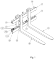
- Fig.1 shows a three-dimensional front view of an embodiment of the system 100 according to the invention with load-bearing elements 191, 192 in a narrow position.
- Two fork tines 191, 192 are suspended in a first, upper guide profile 120.
- the fork tines 191, 192 are supported on a second, lower guide profile 130.
- the first guide profile 120 and the second guide profile 130 are arranged parallel to one another and are connected to one another in a frame-like manner by two vertical connecting elements 140 at a distance from one another.
- the load-bearing elements 190, 191 are connected to drive plates 120, 135, which in turn can be moved horizontally relative to one another or parallel to one another in the longitudinal direction of the guide profiles 120, 130 via drive elements 121, 131.
- the two guide profiles 120, 130 each have a hollow profile, with a drive element 121, 131 being integrated into each guide profile 120, 130 inside the respective guide profile 120, 130.
- Each guide profile 125, 135 has a longitudinal slot 122, 132 through which the holder of the respective drive plate 125, 135 protrudes.
- the second longitudinal slot 132 in the second, lower guide profile 130 is directed upwards and is therefore susceptible to contamination.
- a drive element 121, 131 is integrated into the interior of the respective guide profile 120, 130.
- the driving plate 135 with a moving protective element 150 in the form of a strip closes off this second longitudinal slot 132 at the top and thus prevents contamination of the cavity in the second guide profile 130.
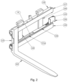
- Fig.2 shows a three-dimensional front view of an embodiment of the system 100 according to the invention with the second load-bearing element 192, which is suspended from the first guide profile and is in an external position, i.e. in a position that is as far out as possible from the center of the device 110.
- the second drive plate 135 is empty, so that the receiving profile 136 can be seen in the second drive plate 135.
- the receiving profile 136 consists of a U-shaped profile, the width of which is dimensioned such that both legs of the U can partially enclose the load-bearing elements 191, 192 used.
- the drive plates 125, 135 establish the connection of the sideshift drive to the fork tines 191, 192. Due to the shape of the receiving profile 126, 136, standard fork tines 191, 192 can be used.
- Fig.3 shows a three-dimensional rear view of an embodiment of the system 100 according to the invention with fork tines 191, 192 in an external position.
- the guide means 121 e, 131 e can be seen.
- the guide means 121 e, 131 e have, on the one hand, the respective holder of the respective driving plate 126, 136 in the form of a cuboid-shaped elevation at the respective end of the respective cylinder housing 121 b, 131 b opposite the outlet side of the respective piston rod 121 c, 131 c, which protrude through the longitudinal slots 122, 132 in the direction of the respective driving plate 125, 135, wherein the longitudinal slots 122, 132 are designed such that they support and guide the cuboid-shaped elevations in a direction perpendicular to the direction of movement.
- the respective drive element 121, 131 lies on an axis with the guide of the respective drive plate 125, 135.
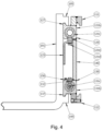
- Fig.4 shows a side section of a system 100 according to the invention.
- the device 110 has a first, upper suspension profile 111 and a second, lower suspension profile 112, with which the device 110 can be attached to a movable or stationary equipment, such as an industrial truck, by being hooked into a corresponding counter profile, for example a vertically movable lifting carriage of a forklift truck.
- the first hanging profile 111 is firmly connected to the device 100, for example by welding.
- the second hanging profile 112 is screwed to the device 100, so that the device 100 can first be hung from the counter profile of a lifting carriage by means of the first hanging profile 111 and then the second hanging profile 112 can be screwed on, so that the device is firmly connected to the lifting carriage in the direction of travel of the forklift truck and cannot tip over when pulling back, for example after a load has been set down.
- the figure shows the second fork tine 192, which is suspended with its suspension profiles in 195 on the first receiving profile 127 of the first guide profile 120 and the second receiving profile 137 of the second guide profile 130.
- the first driving plate 125 is also shown in section.
- the second driving plate 135 is connected with a screw as a fastening means 121 d via a cuboid-shaped elevation to the first drive element 121 of the first guide profile 120, the cuboid-shaped elevation with the first longitudinal slot 122 forming the first guide means 121 e.
- the second guide profile 130 can be seen, which has the second cylinder housing 131 b and the second piston rod 131 c.
- the second longitudinal slot 132 can also be seen, as well as the strip 150, which covers the second longitudinal slot 132 as a protective element.
- Both guide profiles 120, 130 surround the drive element 121, 131 arranged inside it by approximately 90%. By enclosing the drive element 121, 131 by the guide profile 120, 130, the drive element 121, 131 is protected in the guide profile 120, 130 and is held by it in such a way that it cannot bend or buckle even when great force is applied.
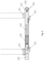
- Fig.5 shows a section from above through the second guide profile 130.
- the connection head 131 f is firmly connected to the frame and the second piston rod 131 c is connected to the connection head 131 f.
- the hydraulic oil runs through two channels through the second piston rod 131 c, once to the bottom side of the piston (load-bearing means move apart) and once to the rod side of the piston in the second cylinder housing 131 b (load-bearing means move towards each other).
- the second guide means 131 e is connected to the movable second cylinder housing 131 b. Sliding elements (not shown) are mounted between the second drive element 131 and the second guide profile 130.
- the first guide profile 120 is constructed in an analogous manner.
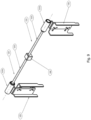
- Fig.6 shows a three-dimensional representation of a drive element 121,131 with a drive plate 125,135.
- the piston rod 121 c, 131 c can be seen, which is fixedly mounted in the guide profile 120, 130 (not shown), whereby the cylinder housing 121 b, 131 b is movable.
- the drive plate 125, 135 is attached to the cylinder housing 121 b, 131 b via the cuboid-shaped elevation as a holder using screws as fastening means 121 d, 131 d.
- the drive plate 125, 135 has a U-shaped receiving profile 126, 136.
- connection head 121 f, 131 f is firmly connected to the piston rod 121 d, 131 c and carries the hydraulic connections 200. Furthermore, the connection head 121 f, 131 f has a fastening means 121 g, 131 g in the form of a receiving bore for a bolt for fastening to the guide profile 120, 130.
- Fig.7 shows a three-dimensional representation of another embodiment of a drive element 121,131 with a drive plate 125,135.
- the driving plates 125, 135 are attached to a sliding arm 121 h, 131 h, which is driven by the respective piston rod 121 c, 131 c.
- Fig.8 shows a three-dimensional front view of an alternative embodiment of the system 100 according to the invention with the second load-bearing element 192, which is suspended from the first guide profile.
- the second carrier plate 135 is empty, so that the receiving profile 136 can be seen in the second carrier plate 135.
- the receiving profile 136 also consists in this embodiment of a U-shaped profile, the width of which is dimensioned such that that both legs of the U can partially enclose the load-bearing elements 191,192 used.
- the drive plates 125, 135 establish the connection of the sideshift drive with the forks 191, 192. Due to the shape of the support profile 126, 136, standard forks 191, 192 can be used.
- each drive plate 125, 135 is driven by the respective drive element 121, 131 in a guide profile 120, 130 and is additionally guided by the other guide profile 130, 120, with both the first longitudinal slot 122 and the second longitudinal slot 132 pointing forwards, i.e. in the direction of extension of the load-bearing elements 191, 192.
- the respective drive plates 125, 135 do not have to be guided by the respective other guide profile 120, 130, but can also be guided by just one guide profile 120, 130.
- an embodiment is also conceivable in which either both longitudinal slots 122, 132 point upwards, i.e. in opposite directions in the horizontal parts of the load-bearing elements 191, 192.
- a system 100 according to the invention is also conceivable in which the first longitudinal slot 122 points downwards in the direction of the second guide profile 130 and the second longitudinal slot 132 points upwards in the direction of the first guide profile 120.
- An arrangement of the guide slots 122, 132 which is the opposite of this is also conceivable.
- Fig.9 shows a three-dimensional representation of another embodiment of a drive element 121 with drive plates 125, 136.
- the drive elements shown are located in the Fig.9
- the first and the second drive element are in one plane and can therefore be installed in a guide profile (not shown in the figure).
- This drive unit 160 can be, for example, an electric or a fluid motor, for example a hydraulic motor.
- the drive unit 160 drives both the first drive element 121 and the second drive element 131 in rotation.
- Spindles for example recirculating ball or threaded spindles, are installed as drive elements 121, 131.
- Sliding arms 121 h, 131 h are moved via the drive elements 121, 131, on which the driving plates 125, 135 can be attached.
- a gear can be integrated in the drive unit (not shown in the figure), which can be switched and can reverse the direction of rotation of a drive element 121, 131, so that both a side-shift movement, in which the drive plates 125, 135 are moved parallel and in the same direction, and an opposite movement of the drive plates 125, 135, as is necessary for adjusting the distance between the load-bearing elements 191, 192 (not shown in the figure), is possible.
Landscapes
- Engineering & Computer Science (AREA)
- Transportation (AREA)
- Structural Engineering (AREA)
- Civil Engineering (AREA)
- Life Sciences & Earth Sciences (AREA)
- Geology (AREA)
- Mechanical Engineering (AREA)
- Forklifts And Lifting Vehicles (AREA)
Claims (20)
- Dispositif (110) de levage et de transport de charges destiné à un montage au niveau d'un équipement mobile ou fixe, comprenant au moins un premier profilé de guidage (120), au moins deux éléments de levage (191, 192) pouvant être montés sur le premier profilé de guidage (120), lesdits au moins deux éléments de levage (191, 192) pouvant être déplacés l'un par rapport à l'autre ou parallèlement l'un à l'autre dans la direction longitudinale du premier profilé de guidage (120) par au moins un élément d'entraînement (121, 131) respectif,le premier profilé de guidage (120) présentant un profilé creux et, dans le premier profilé de guidage (120), un élément d'entraînement (121, 131) étant intégré au moins partiellement à l'intérieur du premier profilé de guidage (120),caractérisé en ce qu'une plaque d'entraînement (125, 135) est reliée par action coordonnée avec un élément d'entraînement (121, 131) et que le guidage de la plaque d'entraînement (122, 135) est également intégré et logé au moins partiellement dans le premier profilé de guidage (120), l'élément d'entraînement (121, 131) et le guidage de la plaque d'entraînement (125, 135) étant situés sur un axe, le premier profilé de guidage (120) présentant une fente longitudinale (122) par laquelle fait saillie le support de la plaque d'entraînement (125, 135), un élément de levage (191, 192) pouvant être respectivement relié par action coordonnée à une plaque d'entraînement (125, 135), le premier profilé de guidage (120) portant lesdits au moins deux éléments de levage (191, 192).
- Dispositif (110) selon la revendication 1,
caractérisé en ce que
le dispositif comporte, en plus du premier profilé de guidage (120), un deuxième profilé de guidage (130) disposé selon une orientation essentiellement parallèle au premier profilé de guidage (120), les profilés de guidage (120, 130) étant reliés entre eux à distance l'un de l'autre par au moins un élément de fixation (140) disposé selon une orientation essentiellement perpendiculaire aux profilés de guidage (120, 130). - Dispositif (110) selon la revendication 1 ou 2,
caractérisé en ce que
chaque élément d'entraînement (121, 131) peut être relié par action coordonnée, d'une part, à une unité d'entraînement (160) et, d'autre part, à une plaque d'entraînement (125, 135). - Dispositif (110) selon la revendication 3,
caractérisé en ce qu'
au moins un élément d'entraînement (121, 131) comporte une broche. - Dispositif (110) selon la revendication 3 ou 4,
caractérisé en ce qu'
au moins un élément d'entraînement (121, 131) comporte un cylindre à fluide (121a, 131a). - Dispositif (110) selon l'une des revendications 3 à 5,
caractérisé en ce que
l'unité d'entraînement (160) comporte un moteur hydraulique. - Dispositif (110) selon l'une des revendications 3 à 5,
caractérisé en ce que
l'unité d'entraînement (160) comporte un moteur électrique. - Dispositif (110) selon l'une des revendications précédentes,
caractérisé en ce que
seul un profilé de guidage (120, 130) comporte un élément d'entraînement (121, 131). - Dispositif (110) selon l'une des revendications 2 à 7,
caractérisé en ce que
les deux profilés de guidage (120, 130) comportent chacun un élément d'entraînement (121, 131). - Dispositif (110) selon l'une des revendications 2 à 9,
caractérisé en ce qu'
au moins un premier profilé de guidage (120) et au moins un deuxième profilé de guidage (130) sont reliés entre eux à distance l'un de l'autre par deux éléments de liaison (140) disposés selon une orientation essentiellement perpendiculaire aux profilés de guidage (120, 130). - Dispositif (110) selon l'une des revendications 9 ou 10,
caractérisé en ce que
les deux profilés de guidage (120, 130) comportent chacun une fente longitudinale (122, 132), les fentes longitudinales (122, 132) étant orientées l'une vers l'autre. - Dispositif (110) selon la revendication 11,
caractérisé en ce que
les deux profilés de guidage (120, 130) sont disposés selon une orientation essentiellement horizontale l'un au-dessus de l'autre de sorte que le premier profilé de guidage (120) se trouve au-dessus du deuxième profilé de guidage (130) et que la deuxième fente longitudinale (132) du deuxième profilé de guidage (130) se trouve sur la face supérieure du deuxième profilé de guidage (130) en direction du premier profilé de guidage (120), la deuxième fente longitudinale (132) du deuxième profilé de guidage (130) étant fermée par un élément de protection (150) se déplaçant avec la deuxième plaque d'entraînement (135). - Dispositif (110) selon l'une des revendications précédentes,
caractérisé en ce qu'
au moins l'un des éléments d'entraînement (121, 131) comporte un cylindre (121 a, 131 a) actionné par un fluide, présentant un boîtier de cylindre (121 b, 131 b) et une tige de piston (121 c, 131 c), des éléments de fixation (121 d, 131 d) et des éléments de guidage (122 d, 132 d) pour la plaque d'entraînement (125, 135) entraînée par l'élément d'entraînement (121, 131) étant au moins partiellement intégrés dans le boîtier de cylindre (121 b, 131 b). - Dispositif (110) selon l'une des revendications précédentes,
caractérisé en ce qu'
au moins un profilé de guidage (120, 130) comporte une section transversale extérieure essentiellement rectangulaire avec un creux essentiellement rond et orienté dans la direction axiale. - Dispositif (110) selon l'une des revendications précédentes,
caractérisé en ce que
la fente longitudinale (1 22, 132) du profilé de guidage (125, 135) comportant un élément d'entraînement (121, 131) est formée de manière à maintenir la plaque d'entraînement (125, 135) en position verticale et à empêcher une rotation de la plaque d'entraînement (125, 135). - Dispositif (110) selon l'une des revendications 9 à 14,
caractérisé en ce que
la première plaque d'entraînement (125) est entraînée dans le premier profilé de guidage (120) par le premier élément d'entraînement (121) et est également guidée par le deuxième profilé de guidage (130), et la deuxième plaque d'entraînement (135) est entraînée dans le deuxième profilé de guidage (130) par le deuxième élément d'entraînement (131) et est également guidée par le premier profilé de guidage (120). - Dispositif (110) selon l'une des revendications précédentes,
caractérisé en ce qu'
au moins un profilé de guidage (120, 130) entoure l'élément d'entraînement respectif (121, 131) à au moins 75 %. - Dispositif (110) selon l'une des revendications précédentes,
caractérisé en ce que
chaque plaque d'entraînement (125, 135) comporte un profilé de levage (126, 136) pour le levage de l'accessoire de levage respectif (191, 192), le profilé de levage (126, 136) pouvant être adapté à la largeur de l'accessoire de levage (191, 192). - Système (100) de levage et de transport de charges destiné à un montage au niveau d'un équipement mobile ou fixe,
caractérisé en ce que
le système (100) comprend au moins un élément de levage (191, 192) et un dispositif (110) selon l'une des revendications précédentes. - Système (100) selon la revendication 19,
caractérisé en ce que
le premier profilé de guidage (120) comporte sur l'un de ses côtés extérieurs un profilé de levage (127) avec un rebord en saillie, au moins un élément de levage (191, 192) pouvant être accroché dans le profilé de levage (127) au moyen d'un profilé d'accrochage (195) usiné de manière symétrique par rapport au profilé de levage (127), le profilé d'accrochage (195) comportant une pièce coulissante qui vient en appui contre le rebord en saillie du profilé de levage (127) lorsque l'élément de levage (193, 192) est accroché dans le profilé de levage (127).
Applications Claiming Priority (2)
| Application Number | Priority Date | Filing Date | Title |
|---|---|---|---|
| DE102017213236.1A DE102017213236A1 (de) | 2017-08-01 | 2017-08-01 | Vorrichtung zur Aufnahme und zum Transport von Lasten |
| PCT/EP2018/070908 WO2019025509A1 (fr) | 2017-08-01 | 2018-08-01 | Dispositif de réception et de transport de charges |
Publications (3)
| Publication Number | Publication Date |
|---|---|
| EP3661866A1 EP3661866A1 (fr) | 2020-06-10 |
| EP3661866C0 EP3661866C0 (fr) | 2024-07-31 |
| EP3661866B1 true EP3661866B1 (fr) | 2024-07-31 |
Family
ID=63103956
Family Applications (1)
| Application Number | Title | Priority Date | Filing Date |
|---|---|---|---|
| EP18749792.0A Active EP3661866B1 (fr) | 2017-08-01 | 2018-08-01 | Dispositif de réception et de transport de charges |
Country Status (5)
| Country | Link |
|---|---|
| US (1) | US20210354965A1 (fr) |
| EP (1) | EP3661866B1 (fr) |
| CN (1) | CN111164043A (fr) |
| DE (1) | DE102017213236A1 (fr) |
| WO (1) | WO2019025509A1 (fr) |
Families Citing this family (4)
| Publication number | Priority date | Publication date | Assignee | Title |
|---|---|---|---|---|
| NL2022025B1 (nl) * | 2018-11-19 | 2020-06-03 | Meijer Holding B V | Vorkenversteller voor een heftruck, heftruck voorzien daarvan en werkwijze voor het verstellen van vorken |
| DE102019129044A1 (de) * | 2019-10-28 | 2021-04-29 | Rogama B.V. | Antriebsvorrichtung |
| DE102019132375A1 (de) * | 2019-11-27 | 2021-05-27 | Rogama B.V. | Lastaufnahmemittel |
| CN121225510A (zh) * | 2025-12-03 | 2025-12-30 | 浙江阿凡特液压科技有限公司 | 一种用于叉车门架的起升装置及其中间升降油缸 |
Family Cites Families (8)
| Publication number | Priority date | Publication date | Assignee | Title |
|---|---|---|---|---|
| DK156424C (da) * | 1987-07-31 | 1990-02-05 | Jl Forklift Truck | Mobilt loefteapparat, saasom gaffeltruck eller gaffelstabler |
| IT1223004B (it) * | 1987-10-28 | 1990-09-12 | Meccaniche Bolzoni Spa Costruz | Unita' a forche per carrelli elevatori |
| DE19602055C1 (de) * | 1996-01-20 | 1997-04-17 | Kaup Gmbh & Co Kg | Seitenschiebereinrichtung für Flurförderzeuge |
| KR20030052129A (ko) * | 2001-12-20 | 2003-06-26 | 한국항공우주연구원 | 지게차 포크 폭 자동 변경장치 |
| DE102011002433A1 (de) | 2011-01-04 | 2012-07-05 | Griptech Gmbh | Vorrichtung zur Aufnahme und zum Transport von Lasten |
| DE102013201818A1 (de) * | 2013-02-05 | 2014-08-07 | Griptech Gmbh | Vorrichtung zur aufnahme und zum transport von lasten |
| US10479662B2 (en) | 2015-06-16 | 2019-11-19 | Rightline Equipment, Inc. | Fork positioner with guided fork holder |
| US10207907B1 (en) * | 2016-09-15 | 2019-02-19 | Rightline Equipment, Inc. | High visibility load clamp with asymmetrical gussets |
-
2017
- 2017-08-01 DE DE102017213236.1A patent/DE102017213236A1/de not_active Ceased
-
2018
- 2018-08-01 WO PCT/EP2018/070908 patent/WO2019025509A1/fr not_active Ceased
- 2018-08-01 EP EP18749792.0A patent/EP3661866B1/fr active Active
- 2018-08-01 CN CN201880063065.7A patent/CN111164043A/zh active Pending
- 2018-08-01 US US16/635,797 patent/US20210354965A1/en not_active Abandoned
Also Published As
| Publication number | Publication date |
|---|---|
| DE102017213236A1 (de) | 2019-02-07 |
| EP3661866C0 (fr) | 2024-07-31 |
| CN111164043A (zh) | 2020-05-15 |
| WO2019025509A1 (fr) | 2019-02-07 |
| US20210354965A1 (en) | 2021-11-18 |
| EP3661866A1 (fr) | 2020-06-10 |
Similar Documents
| Publication | Publication Date | Title |
|---|---|---|
| DE3880958T2 (de) | Gabeleinheit fuer hubwagen. | |
| EP2623256B1 (fr) | Machine-outil dotée d'un dispositif de remplacement de palettes | |
| EP1927770A2 (fr) | Unité linéaire | |
| EP0868965A2 (fr) | Dispositif d'entraínement d'un chariot | |
| DE19602055C1 (de) | Seitenschiebereinrichtung für Flurförderzeuge | |
| EP2661410B1 (fr) | Dispositif de réception et de transport de charges | |
| WO2019025509A1 (fr) | Dispositif de réception et de transport de charges | |
| EP2746001A2 (fr) | Dispositif de préhension doté d'un chariot guidé dans un boîtier | |
| DE10162159B4 (de) | Linearstellglied mit Stoßdämpfungsmechanismus | |
| EP2808289B1 (fr) | Mécanisme d'inclinaison d'un porte-fourche | |
| DE202010002764U1 (de) | Lasttransportierende Konstruktion zur Anbringung an einem Lastschlitten | |
| EP4110563B1 (fr) | Système compact de positionnement à 6 axes | |
| DE19528885C1 (de) | Einrichtung zum gegenläufigen Verschieben von Gabelzinken an Flurförderzeugen | |
| EP4051621B1 (fr) | Dispositif d'entraînement | |
| DE3125384C2 (fr) | ||
| EP1244596B1 (fr) | Appareil rapporte pour chariots de manutention, notamment gerbeuses a fourche | |
| EP4335807A1 (fr) | Dispositif de réception pour la réception à hauteur variable d'un plateau de support | |
| EP3145853B1 (fr) | Support de réception de charge | |
| EP2951118B1 (fr) | Vérin de levage pourvu d'un dispositif à poulies de renvoi pour engin de manutention | |
| DE3907440A1 (de) | Hubschlitten | |
| DE3812335A1 (de) | Zwangsfuehrung fuer paare von kurbelgetriebenen hub-, schub- und/oder zugelementen zur erzeugung einer parallelen linearen bewegung ihrer freien enden | |
| EP0631975B1 (fr) | Accessoire en particulier pour chariot élévateur | |
| LU102625B1 (de) | Hubtisch | |
| DE3125433A1 (de) | Gabelzinke fuer einen gabelstapler | |
| EP2339319A1 (fr) | Dispositif de vérification du jeu d'axe |
Legal Events
| Date | Code | Title | Description |
|---|---|---|---|
| STAA | Information on the status of an ep patent application or granted ep patent |
Free format text: STATUS: UNKNOWN |
|
| STAA | Information on the status of an ep patent application or granted ep patent |
Free format text: STATUS: THE INTERNATIONAL PUBLICATION HAS BEEN MADE |
|
| PUAI | Public reference made under article 153(3) epc to a published international application that has entered the european phase |
Free format text: ORIGINAL CODE: 0009012 |
|
| STAA | Information on the status of an ep patent application or granted ep patent |
Free format text: STATUS: REQUEST FOR EXAMINATION WAS MADE |
|
| 17P | Request for examination filed |
Effective date: 20200302 |
|
| AK | Designated contracting states |
Kind code of ref document: A1 Designated state(s): AL AT BE BG CH CY CZ DE DK EE ES FI FR GB GR HR HU IE IS IT LI LT LU LV MC MK MT NL NO PL PT RO RS SE SI SK SM TR |
|
| AX | Request for extension of the european patent |
Extension state: BA ME |
|
| DAV | Request for validation of the european patent (deleted) | ||
| DAX | Request for extension of the european patent (deleted) | ||
| STAA | Information on the status of an ep patent application or granted ep patent |
Free format text: STATUS: EXAMINATION IS IN PROGRESS |
|
| 17Q | First examination report despatched |
Effective date: 20210325 |
|
| GRAP | Despatch of communication of intention to grant a patent |
Free format text: ORIGINAL CODE: EPIDOSNIGR1 |
|
| STAA | Information on the status of an ep patent application or granted ep patent |
Free format text: STATUS: GRANT OF PATENT IS INTENDED |
|
| INTG | Intention to grant announced |
Effective date: 20240305 |
|
| GRAS | Grant fee paid |
Free format text: ORIGINAL CODE: EPIDOSNIGR3 |
|
| GRAA | (expected) grant |
Free format text: ORIGINAL CODE: 0009210 |
|
| STAA | Information on the status of an ep patent application or granted ep patent |
Free format text: STATUS: THE PATENT HAS BEEN GRANTED |
|
| RAP3 | Party data changed (applicant data changed or rights of an application transferred) |
Owner name: ROGAMA B.V. |
|
| AK | Designated contracting states |
Kind code of ref document: B1 Designated state(s): AL AT BE BG CH CY CZ DE DK EE ES FI FR GB GR HR HU IE IS IT LI LT LU LV MC MK MT NL NO PL PT RO RS SE SI SK SM TR |
|
| REG | Reference to a national code |
Ref country code: CH Ref legal event code: EP Ref country code: GB Ref legal event code: FG4D Free format text: NOT ENGLISH |
|
| REG | Reference to a national code |
Ref country code: DE Ref legal event code: R096 Ref document number: 502018014950 Country of ref document: DE |
|
| REG | Reference to a national code |
Ref country code: IE Ref legal event code: FG4D Free format text: LANGUAGE OF EP DOCUMENT: GERMAN |
|
| U01 | Request for unitary effect filed |
Effective date: 20240826 |
|
| U07 | Unitary effect registered |
Designated state(s): AT BE BG DE DK EE FI FR IT LT LU LV MT NL PT RO SE SI Effective date: 20240904 |
|
| U20 | Renewal fee for the european patent with unitary effect paid |
Year of fee payment: 7 Effective date: 20241204 |
|
| PG25 | Lapsed in a contracting state [announced via postgrant information from national office to epo] |
Ref country code: NO Free format text: LAPSE BECAUSE OF FAILURE TO SUBMIT A TRANSLATION OF THE DESCRIPTION OR TO PAY THE FEE WITHIN THE PRESCRIBED TIME-LIMIT Effective date: 20241031 |
|
| PG25 | Lapsed in a contracting state [announced via postgrant information from national office to epo] |
Ref country code: GR Free format text: LAPSE BECAUSE OF FAILURE TO SUBMIT A TRANSLATION OF THE DESCRIPTION OR TO PAY THE FEE WITHIN THE PRESCRIBED TIME-LIMIT Effective date: 20241101 Ref country code: PL Free format text: LAPSE BECAUSE OF FAILURE TO SUBMIT A TRANSLATION OF THE DESCRIPTION OR TO PAY THE FEE WITHIN THE PRESCRIBED TIME-LIMIT Effective date: 20240731 |
|
| PG25 | Lapsed in a contracting state [announced via postgrant information from national office to epo] |
Ref country code: IS Free format text: LAPSE BECAUSE OF FAILURE TO SUBMIT A TRANSLATION OF THE DESCRIPTION OR TO PAY THE FEE WITHIN THE PRESCRIBED TIME-LIMIT Effective date: 20241130 |
|
| PG25 | Lapsed in a contracting state [announced via postgrant information from national office to epo] |
Ref country code: HR Free format text: LAPSE BECAUSE OF FAILURE TO SUBMIT A TRANSLATION OF THE DESCRIPTION OR TO PAY THE FEE WITHIN THE PRESCRIBED TIME-LIMIT Effective date: 20240731 |
|
| PG25 | Lapsed in a contracting state [announced via postgrant information from national office to epo] |
Ref country code: ES Free format text: LAPSE BECAUSE OF FAILURE TO SUBMIT A TRANSLATION OF THE DESCRIPTION OR TO PAY THE FEE WITHIN THE PRESCRIBED TIME-LIMIT Effective date: 20240731 Ref country code: RS Free format text: LAPSE BECAUSE OF FAILURE TO SUBMIT A TRANSLATION OF THE DESCRIPTION OR TO PAY THE FEE WITHIN THE PRESCRIBED TIME-LIMIT Effective date: 20241031 |
|
| PG25 | Lapsed in a contracting state [announced via postgrant information from national office to epo] |
Ref country code: RS Free format text: LAPSE BECAUSE OF FAILURE TO SUBMIT A TRANSLATION OF THE DESCRIPTION OR TO PAY THE FEE WITHIN THE PRESCRIBED TIME-LIMIT Effective date: 20241031 Ref country code: PL Free format text: LAPSE BECAUSE OF FAILURE TO SUBMIT A TRANSLATION OF THE DESCRIPTION OR TO PAY THE FEE WITHIN THE PRESCRIBED TIME-LIMIT Effective date: 20240731 Ref country code: NO Free format text: LAPSE BECAUSE OF FAILURE TO SUBMIT A TRANSLATION OF THE DESCRIPTION OR TO PAY THE FEE WITHIN THE PRESCRIBED TIME-LIMIT Effective date: 20241031 Ref country code: IS Free format text: LAPSE BECAUSE OF FAILURE TO SUBMIT A TRANSLATION OF THE DESCRIPTION OR TO PAY THE FEE WITHIN THE PRESCRIBED TIME-LIMIT Effective date: 20241130 Ref country code: HR Free format text: LAPSE BECAUSE OF FAILURE TO SUBMIT A TRANSLATION OF THE DESCRIPTION OR TO PAY THE FEE WITHIN THE PRESCRIBED TIME-LIMIT Effective date: 20240731 Ref country code: GR Free format text: LAPSE BECAUSE OF FAILURE TO SUBMIT A TRANSLATION OF THE DESCRIPTION OR TO PAY THE FEE WITHIN THE PRESCRIBED TIME-LIMIT Effective date: 20241101 Ref country code: ES Free format text: LAPSE BECAUSE OF FAILURE TO SUBMIT A TRANSLATION OF THE DESCRIPTION OR TO PAY THE FEE WITHIN THE PRESCRIBED TIME-LIMIT Effective date: 20240731 |
|
| REG | Reference to a national code |
Ref country code: CH Ref legal event code: PL |
|
| PG25 | Lapsed in a contracting state [announced via postgrant information from national office to epo] |
Ref country code: SM Free format text: LAPSE BECAUSE OF FAILURE TO SUBMIT A TRANSLATION OF THE DESCRIPTION OR TO PAY THE FEE WITHIN THE PRESCRIBED TIME-LIMIT Effective date: 20240731 |
|
| PG25 | Lapsed in a contracting state [announced via postgrant information from national office to epo] |
Ref country code: CH Free format text: LAPSE BECAUSE OF NON-PAYMENT OF DUE FEES Effective date: 20240831 Ref country code: MC Free format text: LAPSE BECAUSE OF FAILURE TO SUBMIT A TRANSLATION OF THE DESCRIPTION OR TO PAY THE FEE WITHIN THE PRESCRIBED TIME-LIMIT Effective date: 20240731 |
|
| PG25 | Lapsed in a contracting state [announced via postgrant information from national office to epo] |
Ref country code: CZ Free format text: LAPSE BECAUSE OF FAILURE TO SUBMIT A TRANSLATION OF THE DESCRIPTION OR TO PAY THE FEE WITHIN THE PRESCRIBED TIME-LIMIT Effective date: 20240731 |
|
| PG25 | Lapsed in a contracting state [announced via postgrant information from national office to epo] |
Ref country code: SK Free format text: LAPSE BECAUSE OF FAILURE TO SUBMIT A TRANSLATION OF THE DESCRIPTION OR TO PAY THE FEE WITHIN THE PRESCRIBED TIME-LIMIT Effective date: 20240731 |
|
| PLBE | No opposition filed within time limit |
Free format text: ORIGINAL CODE: 0009261 |
|
| STAA | Information on the status of an ep patent application or granted ep patent |
Free format text: STATUS: NO OPPOSITION FILED WITHIN TIME LIMIT |
|
| GBPC | Gb: european patent ceased through non-payment of renewal fee |
Effective date: 20241031 |
|
| 26N | No opposition filed |
Effective date: 20250501 |
|
| PG25 | Lapsed in a contracting state [announced via postgrant information from national office to epo] |
Ref country code: GB Free format text: LAPSE BECAUSE OF NON-PAYMENT OF DUE FEES Effective date: 20241031 |
|
| PG25 | Lapsed in a contracting state [announced via postgrant information from national office to epo] |
Ref country code: IE Free format text: LAPSE BECAUSE OF NON-PAYMENT OF DUE FEES Effective date: 20240801 |
|
| U20 | Renewal fee for the european patent with unitary effect paid |
Year of fee payment: 8 Effective date: 20250901 |
|
| PG25 | Lapsed in a contracting state [announced via postgrant information from national office to epo] |
Ref country code: CY Free format text: LAPSE BECAUSE OF FAILURE TO SUBMIT A TRANSLATION OF THE DESCRIPTION OR TO PAY THE FEE WITHIN THE PRESCRIBED TIME-LIMIT; INVALID AB INITIO Effective date: 20180801 |
|
| PG25 | Lapsed in a contracting state [announced via postgrant information from national office to epo] |
Ref country code: HU Free format text: LAPSE BECAUSE OF FAILURE TO SUBMIT A TRANSLATION OF THE DESCRIPTION OR TO PAY THE FEE WITHIN THE PRESCRIBED TIME-LIMIT; INVALID AB INITIO Effective date: 20180801 |