EP3662098B1 - Chapeaux de carde - Google Patents
Chapeaux de carde Download PDFInfo
- Publication number
- EP3662098B1 EP3662098B1 EP18737580.3A EP18737580A EP3662098B1 EP 3662098 B1 EP3662098 B1 EP 3662098B1 EP 18737580 A EP18737580 A EP 18737580A EP 3662098 B1 EP3662098 B1 EP 3662098B1
- Authority
- EP
- European Patent Office
- Prior art keywords
- segments
- flat bar
- clothing strip
- bar system
- clothing
- Prior art date
- Legal status (The legal status is an assumption and is not a legal conclusion. Google has not performed a legal analysis and makes no representation as to the accuracy of the status listed.)
- Active
Links
Images


Classifications
-
- D—TEXTILES; PAPER
- D01—NATURAL OR MAN-MADE THREADS OR FIBRES; SPINNING
- D01G—PRELIMINARY TREATMENT OF FIBRES, e.g. FOR SPINNING
- D01G15/00—Carding machines or accessories; Card clothing; Burr-crushing or removing arrangements associated with carding or other preliminary-treatment machines
- D01G15/02—Carding machines
- D01G15/12—Details
- D01G15/14—Constructional features of carding elements, e.g. for facilitating attachment of card clothing
- D01G15/24—Flats or like members
-
- D—TEXTILES; PAPER
- D01—NATURAL OR MAN-MADE THREADS OR FIBRES; SPINNING
- D01G—PRELIMINARY TREATMENT OF FIBRES, e.g. FOR SPINNING
- D01G15/00—Carding machines or accessories; Card clothing; Burr-crushing or removing arrangements associated with carding or other preliminary-treatment machines
- D01G15/84—Card clothing; Manufacture thereof not otherwise provided for
- D01G15/92—Attaching card clothing to carding elements
Definitions
- the invention relates to a flat bar system for use on a card for cotton, chemical fibers or the like, according to the preamble of claim 1.
- a magnetic element is attached to a base of a flat bar with an adhesive layer.
- a sheet of steel is attached to the back of a clothing strip, which faces the flat bar, by means of an adhesive layer.
- the steel sheet can be in contact or
- the steel sheet bonded to the clothing strip can be separated from the magnetic element by using a suitable tool to overcome the holding magnetic force, thereby dismantling it from the flat bar.
- a suitable tool to overcome the holding magnetic force, thereby dismantling it from the flat bar.
- the flat rods used are made of aluminum, with the magnetic elements bonded thereto being flat.
- the fastening principle is subject to DE 10 2004 033 509 A1 the disadvantage of a different linear expansion of the flat bars and the rear side of the clothing strips attached thereto, if temperature changes and thus heating of the clothing occur during operation of the card.
- a high normal force acts on the magnetic connection between a magnetic element of a flat bar and the steel sheet of a clothing strip. The normal force is converted into an axial force relative to the flat bar via the coefficient of friction between the magnetic element and the steel sheet. The resulting force is sufficiently large to cause the flat bar to warp when the clothing heats up, which then leads to a loss of quality.
- the DE 10 2006 005 605 A1 discloses that a metal mesh is introduced into the foundation of the clothing element, which, together with the deflection areas of the wire hooks protruding from the foundation, forms the ferromagnetic counter-surface for the magnetic attachment.
- the invention is based on the object of further developing a flat bar system for use on a card for cotton, man-made fibers or the like in such a way that a magnetic attachment of clothing strips to associated flat bars by means of magnetic force does not lead to distortion of the flat bars and thus to quality losses even when temperature changes occur .
- the backing layer of a clothing strip has a plurality of segments, each containing ferrous material, these segments being arranged at a distance from one another and decoupled from one another in the longitudinal direction of the clothing strip.
- the feature “decoupling” means that—if temperature changes occur during operation of a card—the segments can be displaced relative to one another in the longitudinal direction of the clothing strip. In this way, different coefficients of thermal expansion compared to the material from which the flat rods are made (e.g. aluminum) can be compensated in order to reduce thermally induced changes in shape of the flat rod system and to prevent warping of the flat rod system.
- the invention includes the technical teaching that the at least one segment which is part of the back layer of the clothing strip and has magnetic properties has the same coefficient of thermal expansion as the material from which the flat bar is made, e.g. aluminium.
- the invention is based on the essential knowledge that a backing layer containing iron material is provided on a rear side of a clothing strip facing the flat bar, this iron material not being in the form of a continuous, flat steel sheet but in the form of several individual segments.
- this iron material not being in the form of a continuous, flat steel sheet but in the form of several individual segments.
- adjacent segments are each connected to one another by a solid element, which ensures that the segments can be displaced relative to one another in the longitudinal direction of the clothing strip. This ensures that the back layer of a clothing strip can compensate for the greater thermal expansion of an associated flat bar, which is usually made of aluminum.
- the segments that are provided on the back layer of a clothing strip can each be made of steel.
- the magnetic properties of steel ensure a robust and therefore reliable attachment of a clothing strip to an associated flat bar, while at the same time being able to use suitable tools to detach the clothing strip from the flat bar again.
- the segments can be attached to the back of the clothing strip by means of adhesive.
- adhesive it is possible to glue the segments directly onto the back of a clothing strip.
- the segments can first be glued directly to a carrier layer, which in turn is then attached to the back of a clothing strip, for example by gluing.
- the adhesive strength of the adhesive used exceeds the magnitude of the magnetic force acting between the segments and the magnetic element.
- the segments on the back layer of a clothing strip are separated from one another.
- the segments are isolated from one another and provided in separate pieces.
- This variant also ensures that the back layer of a clothing strip can compensate for the greater thermal expansion of an associated flat bar, which is usually made of aluminum.
- the segments and the solid-state joints with which adjacent segments are connected to one another are designed in one piece, i.e. from a continuous material, e.g. from sheet steel.
- this also has the advantage of simplifying the manufacturability of this plurality of segments, because this eliminates the need for time-consuming attachment of the individual solid state joints to adjacent segments in each case.
- the segments are connected to one another by a flexible material.
- the flexible material can be rubber.
- glue when Gluing the segments to the back of a clothing strip between the segments.
- the segments are embedded in a layer consisting of the flexible material. The magnetic properties of the segments, eg made of steel, are not affected by the flexible material.
- the aforementioned use of the flexible material is also suitable for the case in which the segments provided for the back layer of a clothing strip are connected to one another according to the invention by flexure joints.
- the mode of operation of the solid-state joints namely ensuring that the segments can be displaced in the longitudinal direction of the clothing strip when thermally induced changes in shape occur, is not impaired by the flexible material.
- the 1 shows the flat bar system 100 in a cross-sectional view.
- the flat bar system 100 includes an elongate flat bar 102 which is preferably made of aluminum.
- a magnetic element 103 is attached to the flat bar 102 .
- An elongate clothing strip 104 having clothing points 106 is attached to the flat bar 102 adjacent the magnetic element 103, namely through the use of magnetic force, as will now be explained in detail.
- the right pane of the cross-sectional view of 1 is also shown in an enlarged area. From this it can be seen that the clothing strip 104 has a support element 105 from which the clothing tips 106 protrude downward. Segments 110 are attached by using adhesive 112 on a rear side 107 of the clothing strip 104 or of its supporting element 105 . Similarly, the magnetic element 103 by using adhesive 112 on the Be flat bar 102 attached.
- the magnetic element 103 is of planar design and extends along a longitudinal direction of the flat bar 102 .
- the segments 110 each contain iron material and thus have magnetic properties. This makes it possible to attach the clothing strip 104, to which the segments 110 are glued, by magnetic force on the magnetic element 103 and thus on the flat bar 102. Conveniently, these segments 110 can be made of steel.
- the representation of 1 shows the flat bar system 100 according to the invention in the assembled state when a clothing strip 104 is attached to a flat bar 102 by magnetic force, as explained. If necessary, it is possible to detach the clothing strip 104 from the flat bar 102, for example by using a suitable tool to overcome the magnetic force between the magnetic element 103 and the segments 110 glued to the clothing strip 104.
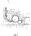
- the flat bar system 100 according to the invention is used for a card K, which is 2 is shown in a side view.
- a card K comprises a feed roller 1, a feed table 2, licker-in 3a, 3b, 3c, a drum 4, a doffer 5, a doctor roller 6, squeezing rollers 7, 8, a fleece guide element 9, a web funnel 10, take-off rollers 11, 12, a revolving flat 13 with flat deflection rollers 13a, 13b, a can 15 and a can coiler 16.
- the flat bars 102 of the flat bar system 100 according to the invention are attached to the revolving flat 13.
- the directions of rotation of the rollers are in 2 indicated with curved arrows. With M the center (axis) of the drum 4 is designated. 4b indicates the direction of rotation of the drum 4.
- C is the direction of rotation of the revolving flat 13 in the carding position
- D is the return transport direction of the flat bars 102 .
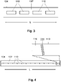
- FIG 3 shows a plan view of the back side 107 of a clothing strip 104 according to an embodiment of the invention, in which the segments 110 are glued to the back side 107 as individual bodies.
- Such a separation of the segments 110 results in the previously explained decoupling of the segments 110 from one another, the segments 110 being displaceable relative to one another in the longitudinal direction L of the clothing strip 104 if thermal expansion occurs when the temperature changes or heats up.
- FIG. 4 10 shows a plan view of the rear side 107 of a clothing strip 104 according to a further embodiment of the present invention.
- the segments 110 are each glued to the back 107 of a clothing strip 104, with adjacent segments 110 being connected to each other by a solid joint 114.
- solid joints 114 - in the same way as in the embodiment of 3 - A displaceability of the segments 110 relative to each other in the longitudinal direction L of the clothing strip 104 guaranteed.
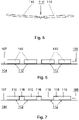
- figure 5 12 shows a simplified side view of two segments 110 which are connected to one another by means of a flexure joint 114'.
- the mode of operation of this flexure joint 114' corresponds to the variant of a flexure joint 114 according to FIG 4 .
- FIG. 6 shows a simplified side view of the back 107 of a clothing strip 104 to illustrate the attachment of the segments 110 to the clothing strip 104.
- the segments 110 are each bonded to the back 107 of the clothing strip 104 by using adhesive 112. If the segments 110 are each made of steel, the segments 110 form a backing layer 108 of the clothing strip 104 which contains ferrous material.
- FIG 7 also shows a simplified side view of the back 107 of a clothing strip 104, and represents a variant of the embodiment of 6 .
- the individual segments 110 are each connected to one another by a flexible material 116 tied together.
- the flexible material 116 can be rubber.
- the connection of the individual segments by the flexible material 116 on the one hand facilitates the handling of the segments 110 in production, because the plurality of segments 110 can be glued as one part to the rear side 107 of a clothing strip 104, and on the other hand prevents the adhesive 112 from Sticking the segments 110 on the back 107 of a clothing strip 104 between the segments 110 emerges.
- a carrier layer 113 (cf. 1 , Enlarged area) to be glued, this carrier layer 113 then in turn being glued to the rear side 107 of a clothing strip 104 .
- a carrier layer 113 fulfills the function of an adhesive and leveling layer and simplifies the handling of a plurality of segments 110.
- the invention now works as follows: Temperature changes can occur during operation of the card K, as a result of which the flat bar system 100 heats up. In this case, a lengthening of both the flat bar 102 and the clothing strip 104 takes place, which is different because of the respective thermal expansion coefficients of the materials used for this purpose. Since the thermal expansion coefficient of aluminum is greater than that of steel, when the flat bar system 100 is heated, the flat bar 102 expands more than the steel segments 110 that are in the back layer 108 of the clothing strip 104 are provided.
- the segments 110 are each arranged at a small distance from one another and are therefore independent of one another.
- Such a decoupling leads to the segments being displaceable relative to one another in the longitudinal direction L of the clothing strip 104 .
- a distortion of the flat bar 102 by the clothing strip 104 is avoided.
Landscapes
- Engineering & Computer Science (AREA)
- Textile Engineering (AREA)
- Preliminary Treatment Of Fibers (AREA)
Claims (10)
- Système formant barre de chapeau (100) destiné à être utilisé sur une carde (K) destinée à du coton, des fibres synthétiques ou similaires, ledit système comprenant une barre de chapeau allongée (102), à laquelle un élément magnétique (103) est fixé, et une bande de garniture allongée (104) qui comporte sur son côté arrière (107), dirigé vers la barre de chapeau (102), une couche arrière (108) qui contient un matériau ferreux, de sorte que la bande de garniture (104) peut être fixée de manière amovible par sa couche arrière (108) par une force magnétique à l'élément magnétique (103) de la barre de chapeau (102), la couche arrière (108) comportant une pluralité de segments (110) qui contiennent chacun un matériau ferreux, les segments (110) étant disposés à distance les uns des autres et étant découplés les uns des autres dans la direction longitudinale (L) de la bande de garniture (104), caractérisé en ce que des segments (110) adjacents sont reliés les uns aux autres à chaque fois par un palier à flexion (114 ; 114') qui garantit une capacité de déplacement des segments (110) les uns par rapport aux autres dans la direction longitudinale (L) de la bande de garniture (104).
- Système formant barre de chapeau (100) selon la revendication 1, caractérisé en ce que les segments (110) sont tous en acier.
- Système formant barre de chapeau (100) selon la revendication 1 ou 2, caractérisé en ce que les segments (110) sont fixés au côté arrière (107) de la bande de garniture (104) au moyen d'un adhésif (112).
- Système formant barre de chapeau (100) selon la revendication 3, caractérisé en ce que les segments (110) sont collés directement sur le côté arrière (107) de la bande de garniture (104).
- Système formant barre de chapeau (100) selon la revendication 3, caractérisé en ce que les segments (110) sont collés directement sur une couche de support (113) qui est fixée au côté arrière (107) de la bande de garniture (104), notamment par collage.
- Système formant barre de chapeau (100) selon l'une des revendications précédentes, caractérisé en ce que les segments (110) sont séparés les uns des autres.
- Système formant barre de chapeau (100) selon la revendication 1, caractérisé en ce que les segments (110) et les paliers à flexion (114 ; 114') prévus entre ceux-ci sont conçus d'une seule pièce.
- Système formant barre de chapeau (100) selon l'une des revendications précédentes, caractérisé en ce que les segments (110) sont reliés les uns aux autres par une matière flexible (116).
- Système formant barre de chapeau (100) selon la revendication 8, caractérisé en ce que les segments (110) sont noyés dans une couche constituée de la matière flexible (116).
- Système formant barre de chapeau (100) selon la revendication 8 ou 9, caractérisé en ce que la matière flexible (116) est en caoutchouc.
Applications Claiming Priority (2)
| Application Number | Priority Date | Filing Date | Title |
|---|---|---|---|
| DE102017117661.6A DE102017117661A1 (de) | 2017-08-03 | 2017-08-03 | Deckelstabsystem |
| PCT/EP2018/067921 WO2019025107A1 (fr) | 2017-08-03 | 2018-07-03 | Système de barreau de chapeau |
Publications (2)
| Publication Number | Publication Date |
|---|---|
| EP3662098A1 EP3662098A1 (fr) | 2020-06-10 |
| EP3662098B1 true EP3662098B1 (fr) | 2022-10-19 |
Family
ID=62837916
Family Applications (1)
| Application Number | Title | Priority Date | Filing Date |
|---|---|---|---|
| EP18737580.3A Active EP3662098B1 (fr) | 2017-08-03 | 2018-07-03 | Chapeaux de carde |
Country Status (4)
| Country | Link |
|---|---|
| EP (1) | EP3662098B1 (fr) |
| CN (1) | CN110799682B (fr) |
| DE (1) | DE102017117661A1 (fr) |
| WO (1) | WO2019025107A1 (fr) |
Family Cites Families (5)
| Publication number | Priority date | Publication date | Assignee | Title |
|---|---|---|---|---|
| GB447689A (en) * | 1934-11-23 | 1936-05-25 | John Platt | Improvements in or relating to carding flats |
| DE102004033509B4 (de) * | 2003-08-25 | 2017-06-29 | Trützschler GmbH & Co Kommanditgesellschaft | Vorrichtung an einer Karde für Baumwolle, Chemiefasern u. dgl., bei der mindestens ein Deckelstab mit einer Deckelgarnitur vorhanden ist |
| DE102006005605A1 (de) * | 2005-06-24 | 2007-01-04 | TRüTZSCHLER GMBH & CO. KG | Vorrichtung an einer Karde für Baumwolle, Chemiefasern u. dgl., bei der mindestens ein Deckelstab mit einer Deckelgarnitur vorhanden ist. |
| DE102009031978A1 (de) * | 2009-07-06 | 2011-01-13 | TRüTZSCHLER GMBH & CO. KG | Vorrichtung an einer Karde oder Krempel zur Einstellung des Arbeitsabstandes zwischen der Trommel und mindestens einer benachbarten Walze |
| CN106835382B (zh) * | 2016-12-13 | 2018-10-26 | 安徽利嘉轻纺制品有限公司 | 一种纺织机针座 |
-
2017
- 2017-08-03 DE DE102017117661.6A patent/DE102017117661A1/de not_active Withdrawn
-
2018
- 2018-07-03 EP EP18737580.3A patent/EP3662098B1/fr active Active
- 2018-07-03 CN CN201880042955.XA patent/CN110799682B/zh active Active
- 2018-07-03 WO PCT/EP2018/067921 patent/WO2019025107A1/fr not_active Ceased
Also Published As
| Publication number | Publication date |
|---|---|
| CN110799682A (zh) | 2020-02-14 |
| WO2019025107A1 (fr) | 2019-02-07 |
| EP3662098A1 (fr) | 2020-06-10 |
| DE102017117661A1 (de) | 2019-02-07 |
| CN110799682B (zh) | 2022-05-24 |
Similar Documents
| Publication | Publication Date | Title |
|---|---|---|
| DE4141133C1 (en) | Support beam for doctor blade bearing on dry cylinder - comprises elongated hollow body having 2 or more convex curved longitudinal walls and composed of composite fibre material e.g. carbon@ fibres | |
| DE2243465C3 (de) | Kontinuierlich arbeitende Presse | |
| DE102009009333A1 (de) | Vorrichtung an einer Spinnereivorbereitungsmaschine, insbesondere Karde, Krempel o. dgl. zum Einstellen eines Arbeitsspaltes | |
| EP0194293B1 (fr) | Element a paroi pour sechoirs de produits a pate alimentaire | |
| EP2123809A2 (fr) | chapeau pour carde | |
| EP3382231B1 (fr) | Procédé d'application d'un élément de connecteur sur une extrémité de courroie de transport | |
| DE102009000630A1 (de) | Flexibelbogen | |
| DE102010053178B4 (de) | Vorrichtung an einer Karde oder Krempel, bei der mindestens ein Arbeits- und/oder Funktionselement vorhanden ist, z. B. Festkardierelement, Wanderdeckel | |
| CH697137A5 (de) | Vorrichtung an einer Karde für Baumwolle oder Chemiefasern, bei der mindestens ein Deckelstab mit einer Deckelgarnitur vorhanden ist. | |
| DE102011009938A1 (de) | Vorrichtung an einer Karde oder Krempel, bei der mindestens ein Arbeits- und/oder Funktionselement vorhanden ist | |
| DE102009042367A1 (de) | Vorrichtung an einer Karde oder Krempel, bei der mindestens ein Festkardierelement vorhanden ist | |
| DE102006005605A1 (de) | Vorrichtung an einer Karde für Baumwolle, Chemiefasern u. dgl., bei der mindestens ein Deckelstab mit einer Deckelgarnitur vorhanden ist. | |
| CH695865A5 (de) | Vorrichtung an einer Karde zur Bearbeitung von Fasermaterial, insbesondere Baumwolle oder Chemiefasern. | |
| DE102009042464A1 (de) | Vorrichtung an einer Karde oder Krempel, bei der mindestens ein Festkardierelement vorhanden ist | |
| WO2019025107A1 (fr) | Système de barreau de chapeau | |
| DE2142002A1 (de) | Schneidvorrichtung | |
| DE102011052229A1 (de) | Kalander | |
| CH700439B1 (de) | Spinnereivorbereitungsmaschine, insbesondere Karde oder Krempel, bei welcher ein Arbeitsspalt zwischen einer Walzengarnitur und Maschinenelementen einstellbar ist. | |
| DD293548A5 (de) | Anordnung eines textilen aufzuges auf uebergabetrommeln von druckmaschinen | |
| DE3118444A1 (de) | Festkardierelement | |
| DE102014105175A1 (de) | Fixkamm für eine Kämmmaschine | |
| DE102011009939A1 (de) | Vorrichtung an einer Karde oder Krempel, bei der mindestens ein Festkardierelement vorhanden ist | |
| DE10203853C5 (de) | Deckelgarnitur für einen Kardendeckel | |
| DE102007060982A1 (de) | Vorrichtung an einer Karde für Baumwolle, Chemiefasern u. dgl., bei der mindestens ein Deckelstab mit einer Deckelgarnitur vorhanden ist | |
| EP3556922B1 (fr) | Dispositif de traitement thermique d'une bande de matière textile |
Legal Events
| Date | Code | Title | Description |
|---|---|---|---|
| STAA | Information on the status of an ep patent application or granted ep patent |
Free format text: STATUS: UNKNOWN |
|
| STAA | Information on the status of an ep patent application or granted ep patent |
Free format text: STATUS: THE INTERNATIONAL PUBLICATION HAS BEEN MADE |
|
| PUAI | Public reference made under article 153(3) epc to a published international application that has entered the european phase |
Free format text: ORIGINAL CODE: 0009012 |
|
| STAA | Information on the status of an ep patent application or granted ep patent |
Free format text: STATUS: REQUEST FOR EXAMINATION WAS MADE |
|
| 17P | Request for examination filed |
Effective date: 20200303 |
|
| AK | Designated contracting states |
Kind code of ref document: A1 Designated state(s): AL AT BE BG CH CY CZ DE DK EE ES FI FR GB GR HR HU IE IS IT LI LT LU LV MC MK MT NL NO PL PT RO RS SE SI SK SM TR |
|
| AX | Request for extension of the european patent |
Extension state: BA ME |
|
| DAV | Request for validation of the european patent (deleted) | ||
| DAX | Request for extension of the european patent (deleted) | ||
| RAP1 | Party data changed (applicant data changed or rights of an application transferred) |
Owner name: TRUETZSCHLER GROUP SE |
|
| GRAP | Despatch of communication of intention to grant a patent |
Free format text: ORIGINAL CODE: EPIDOSNIGR1 |
|
| STAA | Information on the status of an ep patent application or granted ep patent |
Free format text: STATUS: GRANT OF PATENT IS INTENDED |
|
| INTG | Intention to grant announced |
Effective date: 20220722 |
|
| GRAS | Grant fee paid |
Free format text: ORIGINAL CODE: EPIDOSNIGR3 |
|
| GRAA | (expected) grant |
Free format text: ORIGINAL CODE: 0009210 |
|
| STAA | Information on the status of an ep patent application or granted ep patent |
Free format text: STATUS: THE PATENT HAS BEEN GRANTED |
|
| AK | Designated contracting states |
Kind code of ref document: B1 Designated state(s): AL AT BE BG CH CY CZ DE DK EE ES FI FR GB GR HR HU IE IS IT LI LT LU LV MC MK MT NL NO PL PT RO RS SE SI SK SM TR |
|
| REG | Reference to a national code |
Ref country code: GB Ref legal event code: FG4D Free format text: NOT ENGLISH |
|
| REG | Reference to a national code |
Ref country code: CH Ref legal event code: EP |
|
| REG | Reference to a national code |
Ref country code: DE Ref legal event code: R096 Ref document number: 502018010867 Country of ref document: DE |
|
| REG | Reference to a national code |
Ref country code: IE Ref legal event code: FG4D Free format text: LANGUAGE OF EP DOCUMENT: GERMAN |
|
| REG | Reference to a national code |
Ref country code: AT Ref legal event code: REF Ref document number: 1525594 Country of ref document: AT Kind code of ref document: T Effective date: 20221115 |
|
| REG | Reference to a national code |
Ref country code: LT Ref legal event code: MG9D |
|
| REG | Reference to a national code |
Ref country code: NL Ref legal event code: MP Effective date: 20221019 |
|
| PG25 | Lapsed in a contracting state [announced via postgrant information from national office to epo] |
Ref country code: NL Free format text: LAPSE BECAUSE OF FAILURE TO SUBMIT A TRANSLATION OF THE DESCRIPTION OR TO PAY THE FEE WITHIN THE PRESCRIBED TIME-LIMIT Effective date: 20221019 |
|
| PG25 | Lapsed in a contracting state [announced via postgrant information from national office to epo] |
Ref country code: SE Free format text: LAPSE BECAUSE OF FAILURE TO SUBMIT A TRANSLATION OF THE DESCRIPTION OR TO PAY THE FEE WITHIN THE PRESCRIBED TIME-LIMIT Effective date: 20221019 Ref country code: PT Free format text: LAPSE BECAUSE OF FAILURE TO SUBMIT A TRANSLATION OF THE DESCRIPTION OR TO PAY THE FEE WITHIN THE PRESCRIBED TIME-LIMIT Effective date: 20230220 Ref country code: NO Free format text: LAPSE BECAUSE OF FAILURE TO SUBMIT A TRANSLATION OF THE DESCRIPTION OR TO PAY THE FEE WITHIN THE PRESCRIBED TIME-LIMIT Effective date: 20230119 Ref country code: LT Free format text: LAPSE BECAUSE OF FAILURE TO SUBMIT A TRANSLATION OF THE DESCRIPTION OR TO PAY THE FEE WITHIN THE PRESCRIBED TIME-LIMIT Effective date: 20221019 Ref country code: FI Free format text: LAPSE BECAUSE OF FAILURE TO SUBMIT A TRANSLATION OF THE DESCRIPTION OR TO PAY THE FEE WITHIN THE PRESCRIBED TIME-LIMIT Effective date: 20221019 Ref country code: ES Free format text: LAPSE BECAUSE OF FAILURE TO SUBMIT A TRANSLATION OF THE DESCRIPTION OR TO PAY THE FEE WITHIN THE PRESCRIBED TIME-LIMIT Effective date: 20221019 |
|
| PG25 | Lapsed in a contracting state [announced via postgrant information from national office to epo] |
Ref country code: RS Free format text: LAPSE BECAUSE OF FAILURE TO SUBMIT A TRANSLATION OF THE DESCRIPTION OR TO PAY THE FEE WITHIN THE PRESCRIBED TIME-LIMIT Effective date: 20221019 Ref country code: PL Free format text: LAPSE BECAUSE OF FAILURE TO SUBMIT A TRANSLATION OF THE DESCRIPTION OR TO PAY THE FEE WITHIN THE PRESCRIBED TIME-LIMIT Effective date: 20221019 Ref country code: LV Free format text: LAPSE BECAUSE OF FAILURE TO SUBMIT A TRANSLATION OF THE DESCRIPTION OR TO PAY THE FEE WITHIN THE PRESCRIBED TIME-LIMIT Effective date: 20221019 Ref country code: IS Free format text: LAPSE BECAUSE OF FAILURE TO SUBMIT A TRANSLATION OF THE DESCRIPTION OR TO PAY THE FEE WITHIN THE PRESCRIBED TIME-LIMIT Effective date: 20230219 Ref country code: HR Free format text: LAPSE BECAUSE OF FAILURE TO SUBMIT A TRANSLATION OF THE DESCRIPTION OR TO PAY THE FEE WITHIN THE PRESCRIBED TIME-LIMIT Effective date: 20221019 Ref country code: GR Free format text: LAPSE BECAUSE OF FAILURE TO SUBMIT A TRANSLATION OF THE DESCRIPTION OR TO PAY THE FEE WITHIN THE PRESCRIBED TIME-LIMIT Effective date: 20230120 |
|
| REG | Reference to a national code |
Ref country code: DE Ref legal event code: R097 Ref document number: 502018010867 Country of ref document: DE |
|
| PG25 | Lapsed in a contracting state [announced via postgrant information from national office to epo] |
Ref country code: SM Free format text: LAPSE BECAUSE OF FAILURE TO SUBMIT A TRANSLATION OF THE DESCRIPTION OR TO PAY THE FEE WITHIN THE PRESCRIBED TIME-LIMIT Effective date: 20221019 Ref country code: RO Free format text: LAPSE BECAUSE OF FAILURE TO SUBMIT A TRANSLATION OF THE DESCRIPTION OR TO PAY THE FEE WITHIN THE PRESCRIBED TIME-LIMIT Effective date: 20221019 Ref country code: EE Free format text: LAPSE BECAUSE OF FAILURE TO SUBMIT A TRANSLATION OF THE DESCRIPTION OR TO PAY THE FEE WITHIN THE PRESCRIBED TIME-LIMIT Effective date: 20221019 Ref country code: DK Free format text: LAPSE BECAUSE OF FAILURE TO SUBMIT A TRANSLATION OF THE DESCRIPTION OR TO PAY THE FEE WITHIN THE PRESCRIBED TIME-LIMIT Effective date: 20221019 Ref country code: CZ Free format text: LAPSE BECAUSE OF FAILURE TO SUBMIT A TRANSLATION OF THE DESCRIPTION OR TO PAY THE FEE WITHIN THE PRESCRIBED TIME-LIMIT Effective date: 20221019 |
|
| P01 | Opt-out of the competence of the unified patent court (upc) registered |
Effective date: 20230622 |
|
| PLBE | No opposition filed within time limit |
Free format text: ORIGINAL CODE: 0009261 |
|
| STAA | Information on the status of an ep patent application or granted ep patent |
Free format text: STATUS: NO OPPOSITION FILED WITHIN TIME LIMIT |
|
| PG25 | Lapsed in a contracting state [announced via postgrant information from national office to epo] |
Ref country code: SK Free format text: LAPSE BECAUSE OF FAILURE TO SUBMIT A TRANSLATION OF THE DESCRIPTION OR TO PAY THE FEE WITHIN THE PRESCRIBED TIME-LIMIT Effective date: 20221019 Ref country code: AL Free format text: LAPSE BECAUSE OF FAILURE TO SUBMIT A TRANSLATION OF THE DESCRIPTION OR TO PAY THE FEE WITHIN THE PRESCRIBED TIME-LIMIT Effective date: 20221019 |
|
| 26N | No opposition filed |
Effective date: 20230720 |
|
| PG25 | Lapsed in a contracting state [announced via postgrant information from national office to epo] |
Ref country code: SI Free format text: LAPSE BECAUSE OF FAILURE TO SUBMIT A TRANSLATION OF THE DESCRIPTION OR TO PAY THE FEE WITHIN THE PRESCRIBED TIME-LIMIT Effective date: 20221019 |
|
| PG25 | Lapsed in a contracting state [announced via postgrant information from national office to epo] |
Ref country code: MC Free format text: LAPSE BECAUSE OF FAILURE TO SUBMIT A TRANSLATION OF THE DESCRIPTION OR TO PAY THE FEE WITHIN THE PRESCRIBED TIME-LIMIT Effective date: 20221019 |
|
| PG25 | Lapsed in a contracting state [announced via postgrant information from national office to epo] |
Ref country code: MC Free format text: LAPSE BECAUSE OF FAILURE TO SUBMIT A TRANSLATION OF THE DESCRIPTION OR TO PAY THE FEE WITHIN THE PRESCRIBED TIME-LIMIT Effective date: 20221019 |
|
| PG25 | Lapsed in a contracting state [announced via postgrant information from national office to epo] |
Ref country code: LU Free format text: LAPSE BECAUSE OF NON-PAYMENT OF DUE FEES Effective date: 20230703 |
|
| GBPC | Gb: european patent ceased through non-payment of renewal fee |
Effective date: 20230703 |
|
| PG25 | Lapsed in a contracting state [announced via postgrant information from national office to epo] |
Ref country code: LU Free format text: LAPSE BECAUSE OF NON-PAYMENT OF DUE FEES Effective date: 20230703 |
|
| REG | Reference to a national code |
Ref country code: IE Ref legal event code: MM4A |
|
| PG25 | Lapsed in a contracting state [announced via postgrant information from national office to epo] |
Ref country code: GB Free format text: LAPSE BECAUSE OF NON-PAYMENT OF DUE FEES Effective date: 20230703 |
|
| PG25 | Lapsed in a contracting state [announced via postgrant information from national office to epo] |
Ref country code: FR Free format text: LAPSE BECAUSE OF NON-PAYMENT OF DUE FEES Effective date: 20230731 |
|
| PG25 | Lapsed in a contracting state [announced via postgrant information from national office to epo] |
Ref country code: IE Free format text: LAPSE BECAUSE OF NON-PAYMENT OF DUE FEES Effective date: 20230703 |
|
| PG25 | Lapsed in a contracting state [announced via postgrant information from national office to epo] |
Ref country code: IE Free format text: LAPSE BECAUSE OF NON-PAYMENT OF DUE FEES Effective date: 20230703 |
|
| REG | Reference to a national code |
Ref country code: AT Ref legal event code: MM01 Ref document number: 1525594 Country of ref document: AT Kind code of ref document: T Effective date: 20230703 |
|
| PG25 | Lapsed in a contracting state [announced via postgrant information from national office to epo] |
Ref country code: AT Free format text: LAPSE BECAUSE OF NON-PAYMENT OF DUE FEES Effective date: 20230703 |
|
| PG25 | Lapsed in a contracting state [announced via postgrant information from national office to epo] |
Ref country code: AT Free format text: LAPSE BECAUSE OF NON-PAYMENT OF DUE FEES Effective date: 20230703 |
|
| PG25 | Lapsed in a contracting state [announced via postgrant information from national office to epo] |
Ref country code: BG Free format text: LAPSE BECAUSE OF FAILURE TO SUBMIT A TRANSLATION OF THE DESCRIPTION OR TO PAY THE FEE WITHIN THE PRESCRIBED TIME-LIMIT Effective date: 20221019 |
|
| PG25 | Lapsed in a contracting state [announced via postgrant information from national office to epo] |
Ref country code: BG Free format text: LAPSE BECAUSE OF FAILURE TO SUBMIT A TRANSLATION OF THE DESCRIPTION OR TO PAY THE FEE WITHIN THE PRESCRIBED TIME-LIMIT Effective date: 20221019 |
|
| PG25 | Lapsed in a contracting state [announced via postgrant information from national office to epo] |
Ref country code: CY Free format text: LAPSE BECAUSE OF FAILURE TO SUBMIT A TRANSLATION OF THE DESCRIPTION OR TO PAY THE FEE WITHIN THE PRESCRIBED TIME-LIMIT; INVALID AB INITIO Effective date: 20180703 |
|
| PGFP | Annual fee paid to national office [announced via postgrant information from national office to epo] |
Ref country code: TR Payment date: 20250624 Year of fee payment: 8 |
|
| PG25 | Lapsed in a contracting state [announced via postgrant information from national office to epo] |
Ref country code: HU Free format text: LAPSE BECAUSE OF FAILURE TO SUBMIT A TRANSLATION OF THE DESCRIPTION OR TO PAY THE FEE WITHIN THE PRESCRIBED TIME-LIMIT; INVALID AB INITIO Effective date: 20180703 |
|
| PGFP | Annual fee paid to national office [announced via postgrant information from national office to epo] |
Ref country code: DE Payment date: 20250722 Year of fee payment: 8 |
|
| PGFP | Annual fee paid to national office [announced via postgrant information from national office to epo] |
Ref country code: IT Payment date: 20250724 Year of fee payment: 8 |
|
| PGFP | Annual fee paid to national office [announced via postgrant information from national office to epo] |
Ref country code: BE Payment date: 20250718 Year of fee payment: 8 |
|
| PGFP | Annual fee paid to national office [announced via postgrant information from national office to epo] |
Ref country code: CH Payment date: 20250801 Year of fee payment: 8 |