EP3662098B1 - Deckelstabsystem - Google Patents
Deckelstabsystem Download PDFInfo
- Publication number
- EP3662098B1 EP3662098B1 EP18737580.3A EP18737580A EP3662098B1 EP 3662098 B1 EP3662098 B1 EP 3662098B1 EP 18737580 A EP18737580 A EP 18737580A EP 3662098 B1 EP3662098 B1 EP 3662098B1
- Authority
- EP
- European Patent Office
- Prior art keywords
- segments
- flat bar
- clothing strip
- bar system
- clothing
- Prior art date
- Legal status (The legal status is an assumption and is not a legal conclusion. Google has not performed a legal analysis and makes no representation as to the accuracy of the status listed.)
- Active
Links
Images


Classifications
-
- D—TEXTILES; PAPER
- D01—NATURAL OR MAN-MADE THREADS OR FIBRES; SPINNING
- D01G—PRELIMINARY TREATMENT OF FIBRES, e.g. FOR SPINNING
- D01G15/00—Carding machines or accessories; Card clothing; Burr-crushing or removing arrangements associated with carding or other preliminary-treatment machines
- D01G15/02—Carding machines
- D01G15/12—Details
- D01G15/14—Constructional features of carding elements, e.g. for facilitating attachment of card clothing
- D01G15/24—Flats or like members
-
- D—TEXTILES; PAPER
- D01—NATURAL OR MAN-MADE THREADS OR FIBRES; SPINNING
- D01G—PRELIMINARY TREATMENT OF FIBRES, e.g. FOR SPINNING
- D01G15/00—Carding machines or accessories; Card clothing; Burr-crushing or removing arrangements associated with carding or other preliminary-treatment machines
- D01G15/84—Card clothing; Manufacture thereof not otherwise provided for
- D01G15/92—Attaching card clothing to carding elements
Definitions
- the invention relates to a flat bar system for use on a card for cotton, chemical fibers or the like, according to the preamble of claim 1.
- a magnetic element is attached to a base of a flat bar with an adhesive layer.
- a sheet of steel is attached to the back of a clothing strip, which faces the flat bar, by means of an adhesive layer.
- the steel sheet can be in contact or
- the steel sheet bonded to the clothing strip can be separated from the magnetic element by using a suitable tool to overcome the holding magnetic force, thereby dismantling it from the flat bar.
- a suitable tool to overcome the holding magnetic force, thereby dismantling it from the flat bar.
- the flat rods used are made of aluminum, with the magnetic elements bonded thereto being flat.
- the fastening principle is subject to DE 10 2004 033 509 A1 the disadvantage of a different linear expansion of the flat bars and the rear side of the clothing strips attached thereto, if temperature changes and thus heating of the clothing occur during operation of the card.
- a high normal force acts on the magnetic connection between a magnetic element of a flat bar and the steel sheet of a clothing strip. The normal force is converted into an axial force relative to the flat bar via the coefficient of friction between the magnetic element and the steel sheet. The resulting force is sufficiently large to cause the flat bar to warp when the clothing heats up, which then leads to a loss of quality.
- the DE 10 2006 005 605 A1 discloses that a metal mesh is introduced into the foundation of the clothing element, which, together with the deflection areas of the wire hooks protruding from the foundation, forms the ferromagnetic counter-surface for the magnetic attachment.
- the invention is based on the object of further developing a flat bar system for use on a card for cotton, man-made fibers or the like in such a way that a magnetic attachment of clothing strips to associated flat bars by means of magnetic force does not lead to distortion of the flat bars and thus to quality losses even when temperature changes occur .
- the backing layer of a clothing strip has a plurality of segments, each containing ferrous material, these segments being arranged at a distance from one another and decoupled from one another in the longitudinal direction of the clothing strip.
- the feature “decoupling” means that—if temperature changes occur during operation of a card—the segments can be displaced relative to one another in the longitudinal direction of the clothing strip. In this way, different coefficients of thermal expansion compared to the material from which the flat rods are made (e.g. aluminum) can be compensated in order to reduce thermally induced changes in shape of the flat rod system and to prevent warping of the flat rod system.
- the invention includes the technical teaching that the at least one segment which is part of the back layer of the clothing strip and has magnetic properties has the same coefficient of thermal expansion as the material from which the flat bar is made, e.g. aluminium.
- the invention is based on the essential knowledge that a backing layer containing iron material is provided on a rear side of a clothing strip facing the flat bar, this iron material not being in the form of a continuous, flat steel sheet but in the form of several individual segments.
- this iron material not being in the form of a continuous, flat steel sheet but in the form of several individual segments.
- adjacent segments are each connected to one another by a solid element, which ensures that the segments can be displaced relative to one another in the longitudinal direction of the clothing strip. This ensures that the back layer of a clothing strip can compensate for the greater thermal expansion of an associated flat bar, which is usually made of aluminum.
- the segments that are provided on the back layer of a clothing strip can each be made of steel.
- the magnetic properties of steel ensure a robust and therefore reliable attachment of a clothing strip to an associated flat bar, while at the same time being able to use suitable tools to detach the clothing strip from the flat bar again.
- the segments can be attached to the back of the clothing strip by means of adhesive.
- adhesive it is possible to glue the segments directly onto the back of a clothing strip.
- the segments can first be glued directly to a carrier layer, which in turn is then attached to the back of a clothing strip, for example by gluing.
- the adhesive strength of the adhesive used exceeds the magnitude of the magnetic force acting between the segments and the magnetic element.
- the segments on the back layer of a clothing strip are separated from one another.
- the segments are isolated from one another and provided in separate pieces.
- This variant also ensures that the back layer of a clothing strip can compensate for the greater thermal expansion of an associated flat bar, which is usually made of aluminum.
- the segments and the solid-state joints with which adjacent segments are connected to one another are designed in one piece, i.e. from a continuous material, e.g. from sheet steel.
- this also has the advantage of simplifying the manufacturability of this plurality of segments, because this eliminates the need for time-consuming attachment of the individual solid state joints to adjacent segments in each case.
- the segments are connected to one another by a flexible material.
- the flexible material can be rubber.
- glue when Gluing the segments to the back of a clothing strip between the segments.
- the segments are embedded in a layer consisting of the flexible material. The magnetic properties of the segments, eg made of steel, are not affected by the flexible material.
- the aforementioned use of the flexible material is also suitable for the case in which the segments provided for the back layer of a clothing strip are connected to one another according to the invention by flexure joints.
- the mode of operation of the solid-state joints namely ensuring that the segments can be displaced in the longitudinal direction of the clothing strip when thermally induced changes in shape occur, is not impaired by the flexible material.
- the 1 shows the flat bar system 100 in a cross-sectional view.
- the flat bar system 100 includes an elongate flat bar 102 which is preferably made of aluminum.
- a magnetic element 103 is attached to the flat bar 102 .
- An elongate clothing strip 104 having clothing points 106 is attached to the flat bar 102 adjacent the magnetic element 103, namely through the use of magnetic force, as will now be explained in detail.
- the right pane of the cross-sectional view of 1 is also shown in an enlarged area. From this it can be seen that the clothing strip 104 has a support element 105 from which the clothing tips 106 protrude downward. Segments 110 are attached by using adhesive 112 on a rear side 107 of the clothing strip 104 or of its supporting element 105 . Similarly, the magnetic element 103 by using adhesive 112 on the Be flat bar 102 attached.
- the magnetic element 103 is of planar design and extends along a longitudinal direction of the flat bar 102 .
- the segments 110 each contain iron material and thus have magnetic properties. This makes it possible to attach the clothing strip 104, to which the segments 110 are glued, by magnetic force on the magnetic element 103 and thus on the flat bar 102. Conveniently, these segments 110 can be made of steel.
- the representation of 1 shows the flat bar system 100 according to the invention in the assembled state when a clothing strip 104 is attached to a flat bar 102 by magnetic force, as explained. If necessary, it is possible to detach the clothing strip 104 from the flat bar 102, for example by using a suitable tool to overcome the magnetic force between the magnetic element 103 and the segments 110 glued to the clothing strip 104.
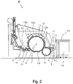
- the flat bar system 100 according to the invention is used for a card K, which is 2 is shown in a side view.
- a card K comprises a feed roller 1, a feed table 2, licker-in 3a, 3b, 3c, a drum 4, a doffer 5, a doctor roller 6, squeezing rollers 7, 8, a fleece guide element 9, a web funnel 10, take-off rollers 11, 12, a revolving flat 13 with flat deflection rollers 13a, 13b, a can 15 and a can coiler 16.
- the flat bars 102 of the flat bar system 100 according to the invention are attached to the revolving flat 13.
- the directions of rotation of the rollers are in 2 indicated with curved arrows. With M the center (axis) of the drum 4 is designated. 4b indicates the direction of rotation of the drum 4.
- C is the direction of rotation of the revolving flat 13 in the carding position
- D is the return transport direction of the flat bars 102 .
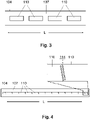
- FIG 3 shows a plan view of the back side 107 of a clothing strip 104 according to an embodiment of the invention, in which the segments 110 are glued to the back side 107 as individual bodies.
- Such a separation of the segments 110 results in the previously explained decoupling of the segments 110 from one another, the segments 110 being displaceable relative to one another in the longitudinal direction L of the clothing strip 104 if thermal expansion occurs when the temperature changes or heats up.
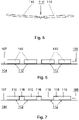
- FIG. 4 10 shows a plan view of the rear side 107 of a clothing strip 104 according to a further embodiment of the present invention.
- the segments 110 are each glued to the back 107 of a clothing strip 104, with adjacent segments 110 being connected to each other by a solid joint 114.
- solid joints 114 - in the same way as in the embodiment of 3 - A displaceability of the segments 110 relative to each other in the longitudinal direction L of the clothing strip 104 guaranteed.
- figure 5 12 shows a simplified side view of two segments 110 which are connected to one another by means of a flexure joint 114'.
- the mode of operation of this flexure joint 114' corresponds to the variant of a flexure joint 114 according to FIG 4 .
- FIG. 6 shows a simplified side view of the back 107 of a clothing strip 104 to illustrate the attachment of the segments 110 to the clothing strip 104.
- the segments 110 are each bonded to the back 107 of the clothing strip 104 by using adhesive 112. If the segments 110 are each made of steel, the segments 110 form a backing layer 108 of the clothing strip 104 which contains ferrous material.
- FIG 7 also shows a simplified side view of the back 107 of a clothing strip 104, and represents a variant of the embodiment of 6 .
- the individual segments 110 are each connected to one another by a flexible material 116 tied together.
- the flexible material 116 can be rubber.
- the connection of the individual segments by the flexible material 116 on the one hand facilitates the handling of the segments 110 in production, because the plurality of segments 110 can be glued as one part to the rear side 107 of a clothing strip 104, and on the other hand prevents the adhesive 112 from Sticking the segments 110 on the back 107 of a clothing strip 104 between the segments 110 emerges.
- a carrier layer 113 (cf. 1 , Enlarged area) to be glued, this carrier layer 113 then in turn being glued to the rear side 107 of a clothing strip 104 .
- a carrier layer 113 fulfills the function of an adhesive and leveling layer and simplifies the handling of a plurality of segments 110.
- the invention now works as follows: Temperature changes can occur during operation of the card K, as a result of which the flat bar system 100 heats up. In this case, a lengthening of both the flat bar 102 and the clothing strip 104 takes place, which is different because of the respective thermal expansion coefficients of the materials used for this purpose. Since the thermal expansion coefficient of aluminum is greater than that of steel, when the flat bar system 100 is heated, the flat bar 102 expands more than the steel segments 110 that are in the back layer 108 of the clothing strip 104 are provided.
- the segments 110 are each arranged at a small distance from one another and are therefore independent of one another.
- Such a decoupling leads to the segments being displaceable relative to one another in the longitudinal direction L of the clothing strip 104 .
- a distortion of the flat bar 102 by the clothing strip 104 is avoided.
Landscapes
- Engineering & Computer Science (AREA)
- Textile Engineering (AREA)
- Preliminary Treatment Of Fibers (AREA)
Description
- Die Erfindung betrifft ein Deckelstabsystem zur Verwendung an einer Karde für Baumwolle, Chemiefasern oder dergleichen, nach dem Oberbegriff von Anspruch 1.
- Nach dem Stand der Technik ist es auf dem Gebiet der Textiltechnik bekannt, bei einer Karde zur Behandlung von Baumwolle, Chemiefasern oder dergleichen Garniturstreifen an zugeordneten Deckelstäben mittels Magnetkraft anzubringen. Zu diesem Zweck ist an einer Fußfläche eines Deckelstabs ein Magnetelement mit einer Klebschicht befestigt. An der Rückseite eines Garniturstreifens, die dem Deckelstab zugewandt ist, ist mittels einer Klebschicht ein Stahlblech befestigt. Zum Anbringen des Garniturstreifens an dem Deckelstab kann das Stahlblech in Kontakt bzw.
- in Wechselwirkung mit dem Magnetelement gebracht werden. Falls ein Austausch des Garniturstreifens erforderlich sein sollte, kann durch Verwendung eines geeigneten Werkzeugs, mit dem die haltende Magnetkraft überwunden wird, eine Abtrennung des mit dem Garniturstreifen verklebten Stahlblechs von dem Magnetelement, und somit eine Demontage von dem Deckelstab erfolgen. Ein solches Befestigungsprinzip eines Garniturstreifens an einem Deckelstab mittels Magnetkraft ist z.B. aus der
DE 10 2004 033 509 A1 bekannt. - Bei einer Karde gemäß der
DE 10 2004 033 509 A1 sind die eingesetzten Deckelstäbe aus Aluminium hergestellt, wobei die damit verklebten Magnetelemente flächig ausgebildet sind. Das Stahlblech, welches jeweils an der Rückseite eines Garniturstreifens aufgeklebt ist, besteht ebenfalls aus einem flächigen durchgehenden Element, das sich entlang der Längsachse der Garniturstreifen erstreckt. Im Hinblick auf die verschiedenen Materialien, nämlich einerseits Aluminium (als Material zur Herstellung der Deckelstäbe), und andererseits Stahl (als Eisenwerkstoff, zur Verwendung an der Rückseite der Garniturstreifen, zwecks magnetischer Anbringung an den Magnetelementen der Deckelstäbe), unterliegt das Befestigungsprinzip gemäßDE 10 2004 033 509 A1 dem Nachteil einer unterschiedlichen Längenausdehnung der Deckelstäbe und der Rückseite der daran angebrachten Garniturstreifen, falls im Betrieb der Karde Temperaturänderungen und somit eine Erwärmung der Garnitur auftreten. Durch die magnetische Verbindung zwischen einem Magnetelement eines Deckelstabs und dem Stahlblech eines Garniturstreifens wirkt eine hohe Normalkraft. Über den Reibungsbeiwert zwischen dem Magnetelement und dem Stahlblech wandelt sich die Normalkraft in eine Axialkraft relativ zum Deckelstab. Die daraus resultierende Kraft ist ausreichend groß, um bei einer Erwärmung der Garnitur eine Verspannung des Deckelstabs zu verursachen, was dann zu Qualitätseinbußen führt. - Die
DE 10 2006 005 605 A1 offenbart, dass in der Fundation des Garniturenelementes ein Metallgewebe eingebracht wird, das zusammen mit den aus der Fundation herausragenden Umlenkbereichen der Drahthäkchen die ferromagnetische Gegenfläche für die magnetische Befestigung bildet. - Entsprechend liegt der Erfindung die Aufgabe zugrunde, ein Deckelstabsystem zur Verwendung an einer Karde für Baumwolle, Chemiefasern oder dergleichen dahingehend weiterzubilden, dass eine magnetische Anbringung von Garniturstreifen an zugehörigen Deckelstäben mittels Magnetkraft auch bei Auftreten von Temperaturänderungen nicht zu Verspannungen der Deckelstäbe und damit zu Qualitätseinbußen führt.
- Diese Aufgabe wird ausgehend von einem Deckelstabsystem zur Verwendung an einer Karde für Baumwolle, Chemiefasern oder dergleichen gemäß dem Oberbegriff des Anspruchs 1 mit den jeweils kennzeichnenden Merkmalen gelöst. Vorteilhafte Weiterbildungen der Erfindung sind in den abhängigen Ansprüchen angegeben.
- Die Erfindung schließt die technische Lehre ein, dass die Rückenschicht eines Garniturstreifens eine Mehrzahl von Segmenten aufweist, die jeweils Eisenwerkstoff enthalten, wobei diese Segmente zueinander beabstandet angeordnet und in Längsrichtung des Garniturstreifens voneinander entkoppelt sind. Im Sinne der vorliegenden Erfindung ist unter dem Merkmal "Entkopplung" zu verstehen, dass - bei Auftreten von Temperaturänderungen im Betrieb einer Karde - eine Verschieblichkeit der Segmente relativ zueinander in Längsrichtung des Garniturstreifens möglich ist. In dieser Weise können unterschiedliche Wärmeausdehnungskoeffizienten im Vergleich zu dem Material, aus dem die Deckelstäbe hergestellt sind (z.B. Aluminium), kompensiert werden, um damit thermisch bedingte Formänderungen des Deckelstabsystems zu reduzieren und eine Verspannung des Deckelstabsystems zu verhindern.
- In gleicher Weise schließt die Erfindung die technische Lehre ein, dass das zumindest eine Segment, welches Teil der Rückenschicht des Garniturstreifens ist und magnetische Eigenschaften aufweist, den gleichen Wärmeausdehnungskoeffizienten wie das Material aufweist, aus dem der Deckelstab hergestellt ist, z.B. Aluminium.
- Der Erfindung liegt die wesentliche Erkenntnis zugrunde, dass an einer dem Deckelstab zugewandten Rückseite eines Garniturstreifens eine Rückenschicht mit darin enthaltenem Eisenwerkstoff vorgesehen ist, wobei dieser Eisenwerkstoff nicht in Form eines durchgehenden flächigen Stahlblechs, sondern in Form von mehreren einzelnen Segmenten vorliegt. Durch die bereits genannte Entkopplung dieser Segmente voneinander ist im Falle von thermisch bedingten Formänderungen eine Verschieblichkeit der Segmente in Längsrichtung des Garniturstreifens möglich, um in Folge dessen eine Verspannung bzw. Verformung des Deckelstabsystems insbesondere quer zu dessen Längsachse zu verhindern.
- Erfindungsgemäß werden benachbarte Segmente jeweils durch ein Festkörperelement miteinander verbunden, mit dem eine Verschieblichkeit der Segmente relativ zueinander in Längsrichtung des Garniturstreifens gewährleistet ist. Damit ist gewährleistet, dass die Rückenschicht eines Garniturstreifens die größere thermische Dehnung eines zugeordneten Deckelstabs, der zumeist aus Aluminium hergestellt ist, ausgleichen kann.
- In vorteilhafter Weiterbildung der Erfindung können die Segmente, die an der Rückenschicht eines Garniturstreifens vorgesehen sind, jeweils aus Stahl hergestellt sein. Durch die magnetischen Eigenschaften von Stahl ist eine robuste und somit betriebssichere Anbringung eines Garniturstreifens an einem zugeordneten Deckelstab gewährleistet, bei gleichzeitiger Möglichkeit, durch Verwendung von geeigneten Werkzeugen den Garniturstreifen wieder von dem Deckelstab lösen zu können.
- In vorteilhafter Weiterbildung der Erfindung können die Segmente mittels Klebstoff an der Rückseite des Garniturstreifens befestigt sein. Hierzu kommt in Betracht, die Segmente unmittelbar auf die Rückseite eines Garniturstreifens aufzukleben. Alternativ hierzu können die Segmente zwecks eines vereinfachten Handlings während der Herstellung zunächst unmittelbar auf eine Trägerschicht aufgeklebt werden, die ihrerseits dann an der Rückseite eines Garniturstreifens z.B. durch Kleben befestigt wird. Diesbezüglich versteht sich, dass die Haftfestigkeit des verwendeten Klebstoffs die Größe der Magnetkraft, die zwischen den Segmenten und dem Magnetelement wirkt, übersteigt. Hierdurch ist einerseits eine betriebssichere Anbringung der Garniturstreifen an den zugeordneten Deckelstäben sichergestellt, und gleichzeitig auch gewährleistet, dass bei einem bestimmungsgemäßen Demontieren der Garniturstreifen von den zugeordneten Deckelstäben die Klebschichten der Segmente bzw. der Trägerschicht nicht gelöst bzw. abgerissen werden.
- In vorteilhafter Weiterbildung der Erfindung kann vorgesehen sein, dass die Segmente an der Rückenschicht eines Garniturstreifens voneinander vereinzelt sind. Anders ausgedrückt, sind hierbei die Segmente voneinander vereinzelt und in separaten Stücken vorgesehen. Auch mit dieser Variante ist gewährleistet, dass die Rückenschicht eines Garniturstreifens die größere thermische Dehnung eines zugeordneten Deckelstabs, der zumeist aus Aluminium hergestellt ist, ausgleichen kann.
- In vorteilhafter Weiterbildung der Erfindung sind die Segmente und die Festkörpergelenke, mit denen benachbarte Segmente miteinander verbunden sind, einstückig ausgebildet, d.h. aus einem durchgehenden Material, z.B. aus einem Stahlblech. Dies führt neben einer vereinfachten Handhabung beim Aufkleben der Segmente an der Rückseite eines Garniturstreifens auch zu dem Vorteil einer vereinfachten Herstellbarkeit dieser Mehrzahl von Segmenten, weil sich damit ein aufwändiges Anbringen der einzelnen Festköpergelenke an jeweils benachbarten Segmenten erübrigt.
- In vorteilhafter Weiterbildung der Erfindung sind die Segmente durch ein flexibles Material miteinander verbunden. Bei dem flexiblen Material kann es sich um Gummi handeln. Insbesondere für den Fall, dass - wie vorstehend bereits genannt - die für die Rückenschicht eines Garniturstreifens vorgesehenen Segmente zunächst in einzelnen Stücken vorliegen, führt dies bei der Handhabung in der Fertigung des erfindungsgemäßen Deckelstabsystems zu dem Vorteil, lediglich ein Teil handzuhaben. Durch die Verbindung der Segmente mit dem flexiblen Material, z.B. Gummi, wird auch vorteilhaft verhindert, dass Klebstoff beim Aufkleben der Segmente auf die Rückseite eines Garniturstreifens zwischen den Segmenten austritt. Hierzu kann auch vorgesehen sein, dass die Segmente in einer Schicht bestehend aus dem flexiblen Material eingebettet sind. Die magnetischen Eigenschaften der Segmente, z.B. bestehend aus Stahl, werden durch das flexible Material nicht beeinflusst. Die vorstehend genannte Verwendung des flexiblen Materials eignet sich auch für den Fall, dass die für die Rückenschicht eines Garniturstreifens vorgesehenen Segmente, erfindungsgemäß, jeweils durch Festkörpergelenke miteinander verbunden sind. Die Wirkungsweise der Festkörpergelenke, nämlich Gewährleistung einer Verschieblichkeit der Segmente in Längsrichtung des Garniturstreifens beim Auftreten von thermisch bedingten Formänderungen, wird durch das flexible Material nicht beeinträchtigt.
- Mit der vorliegenden Erfindung wird erreicht, dass im Betrieb einer Karde und möglicher Temperaturänderungen keine Verspannung der Deckelstäbe und der daran per Magnetkraft angebrachten Garniturstreifen induziert wird.
- Weitere, die Erfindung verbessernde Maßnahmen werden nachstehend gemeinsam mit der Beschreibung eines bevorzugten Ausführungsbeispiels der Erfindung anhand der Figuren näher dargestellt. Es zeigen:
-
Figur 1 eine Querschnittsansicht eines erfindungsgemäßen Deckelstabsystems, bestehend aus einem Deckelstab und einem daran angebrachten Garniturstreifen, -
Figur 2 eine schematische Seitenansicht einer Karde, bei der das erfindungsgemäße Deckelstabsystem vonFig. 1 eingesetzt wird, -
Figur 3 eine Draufsicht auf eine Rückenseite eines Garniturstreifens, der Teil des erfindungsgemäßen Deckelstabsystems vonFig. 1 ist, -
Figur 4 eine Draufsicht auf eine Rückenseite eines Garniturstreifens nach einer weiteren Ausführungsform der Erfindung, als Alternative zuFig. 3 , -
Figur 5 eine Seitenansicht von zwei Segmenten, verbunden mittels Festkörpergelenk, -
Figur 6 eine vereinfachte Seitenansicht einer Rückenseite eines Garniturstreifens, zur Verwendung bei dem erfindungsgemäßen Deckelstabsystem vonFig. 1 , -
Figur 7 eine vereinfachte Seitenansicht einer Rückenseite eines Garniturstreifens nach einer weiteren Ausführungsform der vorliegenden Erfindung, als Alternative zuFig. 6 , und -
Figur 8 ein Diagramm zur Veranschaulichung der unterschiedlichen Wärmedehnungen der Materialien Aluminium und Stahl, bei unterschiedlichen Temperaturen. - Nachstehend sind unter Bezugnahme auf die
Fig. 1-8 bevorzugte Ausführungsformen eines erfindungsgemäßen Deckelstabsystems 100 erläutert, das zur Verwendung an einer Karde für Baumwolle, Chemiefasern oder dergleichen vorgesehen ist. Gleiche Merkmale in der Zeichnung sind jeweils mit gleichen Bezugszeichen versehen. An dieser Stelle versteht sich, dass die Zeichnung lediglich vereinfacht und insbesondere ohne Maßstab dargestellt ist. - Die
Fig. 1 zeigt das Deckelstabsystem 100 in einer Querschnittsansicht. Das Deckelstabsystem 100 umfasst einen länglichen Deckelstab 102, der vorzugsweise aus Aluminium hergestellt ist. An dem Deckelstab 102 ist ein Magnetelement 103 befestigt. An dem Deckelstab 102 ist angrenzend an das Magnetelement 103 ein länglicher Garniturstreifen 104 mit Garniturspitzen 106 angebracht, nämlich durch den Einsatz von Magnetkraft, wie nun im Detail erläutert ist. - Der rechte Bereich der Querschnittsansicht von
Fig. 1 ist zusätzlich in einem vergrößerten Bereich gezeigt. Hieraus ist ersichtlich, dass der Garniturstreifen 104 ein Tragelement 105 aufweist, von dem die Garniturspitzen 106 nach unten herausragen. An einer Rückseite 107 des Garniturstreifens 104 bzw. von dessen Tragelement 105 sind Segmente 110 durch Verwendung von Klebstoff 112 befestigt. In gleicher Weise kann das Magnetelement 103 durch Verwendung von Klebstoff 112 an dem Deckelstab 102 befestigt sein. - In der Darstellung von
Fig. 1 ist nicht zu erkennen, dass das Magnetelement 103 flächig ausgebildet ist, und sich dabei entlang einer Längsrichtung des Deckelstabs 102 erstreckt. - Die Segmente 110 enthalten jeweils Eisenwerkstoff, und weisen somit magnetische Eigenschaften auf. Hierdurch ist es möglich, den Garniturstreifen 104, an dem die Segmente 110 verklebt sind, durch Magnetkraft an dem Magnetelement 103 und somit an dem Deckelstab 102 anzubringen. Zweckmäßigerweise können diese Segmente 110 aus Stahl hergestellt sein.
- Die Darstellung von
Fig. 1 zeigt das erfindungsgemäße Deckelstabsystem 100 im montierten Zustand, wenn ein Garniturstreifen 104 wie erläutert durch Magnetkraft an einem Deckelstab 102 angebracht ist. Bei Bedarf ist es möglich, den Garniturstreifen 104 von dem Deckelstab 102 zu lösen, indem z.B. durch Verwendung eines geeigneten Werkzeugs die Magnetkraft zwischen dem Magnetelement 103 und den an den Garniturstreifen 104 festgeklebten Segmenten 110 überwunden wird. - Das erfindungsgemäße Deckelstabsystem 100 dient zur Verwendung bei einer Karde K, die in
Fig. 2 in einer Seitenansicht gezeigt ist. Eine solche Karde K umfasst eine Speisewalze 1, einen Speisetisch 2, Vorreißer 3a, 3b, 3c, eine Trommel 4, einen Abnehmer 5, eine Abstreichwalze 6, Quetschwalzen 7, 8, ein Vliesleitelement 9, einen Flortrichter 10, Abzugswalzen 11, 12, einen Wanderdeckel 13 mit Deckelumlenkrollen 13a, 13b, eine Kanne 15 und einen Kannenstock 16. Die Deckelstäbe 102 des erfindungsgemäßen Deckelstabsystems 100 sind an dem Wanderdeckel 13 angebracht. Die Drehrichtungen der Walzen sind inFig. 2 mit gebogenen Pfeilen angedeutet. Mit M ist der Mittelpunkt (Achse) der Trommel 4 bezeichnet. 4b gibt die Drehrichtung der Trommel 4 an. Mit C ist die Drehrichtung des Wanderdeckels 13 in Kardierstellung, und mit D ist die Rücktransportrichtung der Deckelstäbe 102 bezeichnet. - Nachfolgend sind in den
Fig. 3-7 weitere Details bezüglich der Segmente 110 und deren Anbringung an der Rückseite 107 eines Garniturstreifens 104 gezeigt und erläutert. -
Fig. 3 zeigt eine Draufsicht auf die Rückenseite 107 eines Garniturstreifens 104 nach einer Ausführungsform der Erfindung, bei der die Segmente 110 als vereinzelte Körper auf die Rückseite 107 geklebt sind. Durch eine solche Vereinzelung der Segmente 110 ist die vorstehend erläuterte Entkopplung der Segmente 110 voneinander gegeben, wobei die Segmente 110 in Längsrichtung L des Garniturstreifens 104 relativ zueinander verschieblich sind, falls bei einer Temperaturänderung bzw. Erwärmung eine thermische Ausdehnung auftritt. -
Fig. 4 zeigt eine Draufsicht auf die Rückseite 107 eines Garniturstreifens 104 nach einer weiteren Ausführungsform der vorliegenden Erfindung. Hierbei sind die Segmente 110 jeweils auf die Rückseite 107 eines Garniturstreifens 104 geklebt, wobei benachbarte Segmente 110 jeweils durch ein Festkörpergelenk 114 miteinander verbunden sind. Durch die Festkörpergelenke 114 ist - in gleicher Weise wie bei der Ausführungsform vonFig. 3 - eine Verschieblichkeit der Segmente 110 relativ zueinander in Längsrichtung L des Garniturstreifens 104 gewährleistet. -
Fig. 5 zeigt eine vereinfachte Seitenansicht von zwei Segmenten 110, die mittels eines Festkörpergelenks 114' miteinander verbunden sind. Die Wirkungsweise dieses Festkörpergelenks 114' entspricht der Variante eines Festkörpergelenks 114 gemäßFig. 4 . -
Fig. 6 zeigt eine vereinfachte Seitenansicht der Rückseite 107 eines Garniturstreifens 104, zur Verdeutlichung der Befestigung der Segmente 110 an dem Garniturstreifen 104. Hierbei sind die Segmente 110 durch Verwendung von Klebstoff 112 jeweils an der Rückseite 107 des Garniturstreifens 104 verklebt. Falls die Segmente 110 jeweils aus Stahl hergestellt sind, bilden die Segmente 110 eine Rückenschicht 108 des Garniturstreifens 104 aus, die Eisenwerkstoff enthält. -
Fig. 7 zeigt ebenfalls eine vereinfachte Seitenansicht der Rückseite 107 eines Garniturstreifens 104, und stellt eine Variante zur Ausführungsform vonFig. 6 dar. Bei der Ausführungsform vonFig. 7 sind die einzelnen Segmente 110 jeweils durch ein flexibles Material 116 miteinander verbunden. Bei dem flexiblen Material 116 kann es sich um Gummi handeln. Die Verbindung der einzelnen Segmente durch das flexible Material 116 erleichtert einerseits die Handhabung der Segmente 110 in der Fertigung, weil die Mehrzahl von Segmenten 110 als ein Teil auf die Rückseite 107 eines Garniturstreifens 104 aufgeklebt werden können, und verhindert andererseits, dass der Klebstoff 112 beim Aufkleben der Segmente 110 auf die Rückseite 107 eines Garniturstreifens 104 zwischen den Segmenten 110 austritt. - Bezüglich der Ausführungsformen von
Fig. 6 und Fig. 7 darf darauf hingewiesen werden, dass es alternativ hierzu auch möglich ist, die Segmente 110 zunächst auf eine Trägerschicht 113 (vgl.Fig. 1 , vergrößerter Bereich) aufzukleben, wobei diese Trägerschicht 113 dann ihrerseits auf die Rückseite 107 eines Garniturstreifens 104 geklebt wird. Hierbei erfüllt eine solche Trägerschicht 113 die Funktion einer Klebstoff- und Ausgleichsschicht, und vereinfacht die Handhabung einer Mehrzahl von Segmenten 110. - An dieser Stelle darf gesondert darauf hingewiesen werden, dass die Verwendung des flexiblen Materials 116 (vgl.
Fig. 6, Fig. 7 ), z.B. Gummi, auch in Verbindung mit einem Festkörpergelenk 114, 114' (vgl.Fig. 4 ,Fig. 5 ) möglich ist, um z.B. das Austreten von Klebstoff im Bereich der Festkörpergelenke 114, 114' zu verhindern. Dank der flexiblen Eigenschaften von Gummi wird die Wirkungsweise der Festkörpergelenke 114, 114' nicht beeinträchtigt. - Die Erfindung funktioniert nun wie folgt:
Im Betrieb der Karde K können Temperaturänderungen auftreten, in Folge derer sich das Deckelstabsystem 100 erwärmt. Hierbei findet eine Längendehnung sowohl des Deckelstabs 102 als auch des Garniturstreifens 104 statt, die wegen der jeweiligen Wärmeausdehnungskoeffizienten der hierzu verwendeten Materialien unterschiedlich ist. Da der Wärmeausdehnungskoeffizient von Aluminium größer ist als jener von Stahl, dehnt sich bei einer Erwärmung des Deckelstabsystems 100 der Deckelstab 102 stärker aus als die Segmente 110 aus Stahl, die in der Rückenschicht 108 des Garniturstreifens 104 vorgesehen sind. - Erfindungsgemäß wird nun bei einer Erwärmung des Deckelstabsystems 100 eine unterschiedliche Längenausdehnung des Deckelstabs 102 und der Rückenschicht 108 des Garniturstreifens 104 dadurch verhindert, dass die Segmente 110 - wie erläutert - in Längsrichtung L des Garniturstreifens 104 voneinander entkoppelt sind. Wie in den
Fig. 3, 4 ,6 und 7 zu erkennen, sind die Segmente 110 jeweils in einem geringen Abstand zueinander angeordnet und damit unabhängig voneinander. Eine solche Entkopplung führt zu einer Verschieblichkeit der Segmente relativ zueinander in Längsrichtung L des Garniturstreifens 104. Entsprechend kann die Rückenschicht 108 mit den (Stahl-)Segmenten 110 die größere thermische Dehnung des Deckelstabs 102 ausgleichen. Im Ergebnis wird hierdurch eine Verspannung des Deckelstabes 102 durch den Garniturstreifens 104 vermieden. - Der vorstehend erläuterte Zusammenhang einer Kompensation der thermisch bedingten unterschiedlichen Verformung der Materialien Aluminium und Stahl ist in dem Diagramm von
Fig. 8 nochmals veranschaulicht. Hierin sind mit T1 und T2 unterschiedliche Temperaturen gezeigt, wobei die Temperatur T2 größer ist als die Temperatur T1. InFig. 8 ist durch die Bezugszeichen 102 und 110 angedeutet, dass das Material Aluminium zur Herstellung eines Deckelstabs 102 verwendet wird, wobei mit dem Material Stahl jeweils die Segmente 110 gebildet werden. - Die Längenausdehnung bei der erhöhten Temperatur T2 gemäß
Fig. 8 verdeutlicht, dass es wegen der Mehrzahl der Segmente 110 bestehend aus Stahl möglich ist, die an sich größere Längenausdehnung des Aluminiums auszugleichen. Dies ist für den Temperaturbereich von T2 durch die senkrechte gestrichelte Linie symbolisiert. Ein solcher Längenausgleich wäre durch ein einziges durchgehendes Stahl-Segment in der Rückenschicht 108 eines Garniturstreifens 104 nicht möglich. -
- 1 Speisewalze
- 2 Speisetisch
- 3a, 3b, 3c Vorreißer
- 4 Trommel
- 5 Abnehmer
- 6 Abstreichwalze
- 7, 8 Quetschwalze
- 9 Vliesleitelement
- 10 Flortrichter
- 11, 12 Abzugswalzen
- 13 Wanderdeckel
- 13a, 13b Deckelumlenkrollen
- 15 Kanne
- 16 Kannenstock
- 100 Deckelstabsystem
- 102 Deckelstab (z.B. aus Aluminium)
- 103 Magnetelement
- 104 Garniturstreifen
- 105 Tragelement (des Garniturstreifens 104)
- 106 Garniturspitzen
- 107 Rückseite (des Garniturstreifens 104)
- 108 Rückenschicht (des Garniturstreifens 104)
- 110 Segment
- 112 Klebstoff
- 113 Trägerschicht (Klebstoff- und Ausgleichsschicht)
- 114 Festkörpergelenk
- 116 Flexibles Material (z.B. Gummi)
- C Drehrichtung (des Wanderdeckels 13)
- D Rücktransportrichtung (der Deckelstäbe 102)
- K Karde
- L Längsrichtung (des Garniturstreifens 104)
- M Mittelpunkt (der Trommel 4)
Claims (10)
- Deckelstabsystem (100) zur Verwendung an einer Karde (K) für Baumwolle, Chemiefasern oder dergleichen, umfassend einen länglichen Deckelstab (102), an dem ein Magnetelement (103) befestigt ist, und einen länglichen Garniturstreifen (104), der an seiner dem Deckelstab (102) zugewandten Rückseite (107) eine Rückenschicht (108) aufweist, die Eisenwerkstoff enthält, so dass der Garniturstreifen (104) mit seiner Rückenschicht (108) an dem Magnetelement (103) des Deckelstabs (102) durch Magnetkraft lösbar befestigbar ist, wobei die Rückenschicht (108) eine Mehrzahl von Segmenten (110) aufweist, die jeweils Eisenwerkstoff enthalten, wobei die Segmente (110) zueinander beabstandet angeordnet und in Längsrichtung (L) des Garniturstreifens (104) voneinander entkoppelt sind, dadurch gekennzeichnet, dass benachbarte Segmente (110) jeweils durch ein Festkörpergelenk (114; 114') miteinander verbunden sind, mit dem eine Verschieblichkeit der Segmente (110) relativ zueinander in Längsrichtung (L) des Garniturstreifens (104) gewährleistet ist.
- Deckelstabsystem (100) nach Anspruch 1, dadurch gekennzeichnet, dass die Segmente (110) jeweils aus Stahl hergestellt sind.
- Deckelstabsystem (100) nach Anspruch 1 oder 2, dadurch gekennzeichnet, dass die Segmente (110) mittels Klebstoff (112) an der Rückseite (107) des Garniturstreifens (104) befestigt sind.
- Deckelstabsystem (100) nach Anspruch 3, dass die Segmente (110) unmittelbar auf die Rückseite (107) des Garniturstreifens (104) aufgeklebt sind.
- Deckelstabsystem (100) nach Anspruch 3, dadurch gekennzeichnet, dass die Segmente (110) unmittelbar auf eine Trägerschicht (113) aufgeklebt sind, die an der Rückseite (107) des Garniturstreifens (104) insbesondere durch Kleben befestigt ist.
- Deckelstabsystem (100) nach einem der vorhergehenden Ansprüche, dadurch gekennzeichnet, dass die Segmente (110) voneinander vereinzelt sind.
- Deckelstabsystem (100) nach Anspruch 1, dadurch gekennzeichnet, dass die Segmente (110) und die dazwischen vorgesehenen Festkörpergelenke (114; 114') einstückig ausgebildet sind.
- Deckelstabsystem (100) nach einem der vorhergehenden Ansprüche, dadurch gekennzeichnet, dass die Segmente (110) durch ein flexibles Material (116) miteinander verbunden sind.
- Deckelstabsystem (100) nach Anspruch 8, dadurch gekennzeichnet, dass die Segmente (110) in einer Schicht bestehend aus dem flexiblen Material (116) eingebettet sind.
- Deckelstabsystem (100) nach Anspruch 8 oder 9, dadurch gekennzeichnet, dass das flexible Material (116) aus Gummi gebildet ist.
Applications Claiming Priority (2)
| Application Number | Priority Date | Filing Date | Title |
|---|---|---|---|
| DE102017117661.6A DE102017117661A1 (de) | 2017-08-03 | 2017-08-03 | Deckelstabsystem |
| PCT/EP2018/067921 WO2019025107A1 (de) | 2017-08-03 | 2018-07-03 | Deckelstabsystem |
Publications (2)
| Publication Number | Publication Date |
|---|---|
| EP3662098A1 EP3662098A1 (de) | 2020-06-10 |
| EP3662098B1 true EP3662098B1 (de) | 2022-10-19 |
Family
ID=62837916
Family Applications (1)
| Application Number | Title | Priority Date | Filing Date |
|---|---|---|---|
| EP18737580.3A Active EP3662098B1 (de) | 2017-08-03 | 2018-07-03 | Deckelstabsystem |
Country Status (4)
| Country | Link |
|---|---|
| EP (1) | EP3662098B1 (de) |
| CN (1) | CN110799682B (de) |
| DE (1) | DE102017117661A1 (de) |
| WO (1) | WO2019025107A1 (de) |
Family Cites Families (5)
| Publication number | Priority date | Publication date | Assignee | Title |
|---|---|---|---|---|
| GB447689A (en) * | 1934-11-23 | 1936-05-25 | John Platt | Improvements in or relating to carding flats |
| DE102004033509B4 (de) * | 2003-08-25 | 2017-06-29 | Trützschler GmbH & Co Kommanditgesellschaft | Vorrichtung an einer Karde für Baumwolle, Chemiefasern u. dgl., bei der mindestens ein Deckelstab mit einer Deckelgarnitur vorhanden ist |
| DE102006005605A1 (de) * | 2005-06-24 | 2007-01-04 | TRüTZSCHLER GMBH & CO. KG | Vorrichtung an einer Karde für Baumwolle, Chemiefasern u. dgl., bei der mindestens ein Deckelstab mit einer Deckelgarnitur vorhanden ist. |
| DE102009031978A1 (de) * | 2009-07-06 | 2011-01-13 | TRüTZSCHLER GMBH & CO. KG | Vorrichtung an einer Karde oder Krempel zur Einstellung des Arbeitsabstandes zwischen der Trommel und mindestens einer benachbarten Walze |
| CN106835382B (zh) * | 2016-12-13 | 2018-10-26 | 安徽利嘉轻纺制品有限公司 | 一种纺织机针座 |
-
2017
- 2017-08-03 DE DE102017117661.6A patent/DE102017117661A1/de not_active Withdrawn
-
2018
- 2018-07-03 EP EP18737580.3A patent/EP3662098B1/de active Active
- 2018-07-03 CN CN201880042955.XA patent/CN110799682B/zh active Active
- 2018-07-03 WO PCT/EP2018/067921 patent/WO2019025107A1/de not_active Ceased
Also Published As
| Publication number | Publication date |
|---|---|
| CN110799682A (zh) | 2020-02-14 |
| WO2019025107A1 (de) | 2019-02-07 |
| EP3662098A1 (de) | 2020-06-10 |
| DE102017117661A1 (de) | 2019-02-07 |
| CN110799682B (zh) | 2022-05-24 |
Similar Documents
| Publication | Publication Date | Title |
|---|---|---|
| DE4141133C1 (en) | Support beam for doctor blade bearing on dry cylinder - comprises elongated hollow body having 2 or more convex curved longitudinal walls and composed of composite fibre material e.g. carbon@ fibres | |
| DE2243465C3 (de) | Kontinuierlich arbeitende Presse | |
| DE102009009333A1 (de) | Vorrichtung an einer Spinnereivorbereitungsmaschine, insbesondere Karde, Krempel o. dgl. zum Einstellen eines Arbeitsspaltes | |
| EP0194293B1 (de) | Wandelement für teigwarentrockner | |
| EP2123809A2 (de) | Deckelstab für eine Karde | |
| EP3382231B1 (de) | Verfahren zum anbringen eines verbinderelements an einem gurtende eines fördergurts | |
| DE102009000630A1 (de) | Flexibelbogen | |
| DE102010053178B4 (de) | Vorrichtung an einer Karde oder Krempel, bei der mindestens ein Arbeits- und/oder Funktionselement vorhanden ist, z. B. Festkardierelement, Wanderdeckel | |
| CH697137A5 (de) | Vorrichtung an einer Karde für Baumwolle oder Chemiefasern, bei der mindestens ein Deckelstab mit einer Deckelgarnitur vorhanden ist. | |
| DE102011009938A1 (de) | Vorrichtung an einer Karde oder Krempel, bei der mindestens ein Arbeits- und/oder Funktionselement vorhanden ist | |
| DE102009042367A1 (de) | Vorrichtung an einer Karde oder Krempel, bei der mindestens ein Festkardierelement vorhanden ist | |
| DE102006005605A1 (de) | Vorrichtung an einer Karde für Baumwolle, Chemiefasern u. dgl., bei der mindestens ein Deckelstab mit einer Deckelgarnitur vorhanden ist. | |
| CH695865A5 (de) | Vorrichtung an einer Karde zur Bearbeitung von Fasermaterial, insbesondere Baumwolle oder Chemiefasern. | |
| DE102009042464A1 (de) | Vorrichtung an einer Karde oder Krempel, bei der mindestens ein Festkardierelement vorhanden ist | |
| WO2019025107A1 (de) | Deckelstabsystem | |
| DE2142002A1 (de) | Schneidvorrichtung | |
| DE102011052229A1 (de) | Kalander | |
| CH700439B1 (de) | Spinnereivorbereitungsmaschine, insbesondere Karde oder Krempel, bei welcher ein Arbeitsspalt zwischen einer Walzengarnitur und Maschinenelementen einstellbar ist. | |
| DD293548A5 (de) | Anordnung eines textilen aufzuges auf uebergabetrommeln von druckmaschinen | |
| DE3118444A1 (de) | Festkardierelement | |
| DE102014105175A1 (de) | Fixkamm für eine Kämmmaschine | |
| DE102011009939A1 (de) | Vorrichtung an einer Karde oder Krempel, bei der mindestens ein Festkardierelement vorhanden ist | |
| DE10203853C5 (de) | Deckelgarnitur für einen Kardendeckel | |
| DE102007060982A1 (de) | Vorrichtung an einer Karde für Baumwolle, Chemiefasern u. dgl., bei der mindestens ein Deckelstab mit einer Deckelgarnitur vorhanden ist | |
| EP3556922B1 (de) | Vorrichtung zum thermischen behandeln einer textilen warenbahn |
Legal Events
| Date | Code | Title | Description |
|---|---|---|---|
| STAA | Information on the status of an ep patent application or granted ep patent |
Free format text: STATUS: UNKNOWN |
|
| STAA | Information on the status of an ep patent application or granted ep patent |
Free format text: STATUS: THE INTERNATIONAL PUBLICATION HAS BEEN MADE |
|
| PUAI | Public reference made under article 153(3) epc to a published international application that has entered the european phase |
Free format text: ORIGINAL CODE: 0009012 |
|
| STAA | Information on the status of an ep patent application or granted ep patent |
Free format text: STATUS: REQUEST FOR EXAMINATION WAS MADE |
|
| 17P | Request for examination filed |
Effective date: 20200303 |
|
| AK | Designated contracting states |
Kind code of ref document: A1 Designated state(s): AL AT BE BG CH CY CZ DE DK EE ES FI FR GB GR HR HU IE IS IT LI LT LU LV MC MK MT NL NO PL PT RO RS SE SI SK SM TR |
|
| AX | Request for extension of the european patent |
Extension state: BA ME |
|
| DAV | Request for validation of the european patent (deleted) | ||
| DAX | Request for extension of the european patent (deleted) | ||
| RAP1 | Party data changed (applicant data changed or rights of an application transferred) |
Owner name: TRUETZSCHLER GROUP SE |
|
| GRAP | Despatch of communication of intention to grant a patent |
Free format text: ORIGINAL CODE: EPIDOSNIGR1 |
|
| STAA | Information on the status of an ep patent application or granted ep patent |
Free format text: STATUS: GRANT OF PATENT IS INTENDED |
|
| INTG | Intention to grant announced |
Effective date: 20220722 |
|
| GRAS | Grant fee paid |
Free format text: ORIGINAL CODE: EPIDOSNIGR3 |
|
| GRAA | (expected) grant |
Free format text: ORIGINAL CODE: 0009210 |
|
| STAA | Information on the status of an ep patent application or granted ep patent |
Free format text: STATUS: THE PATENT HAS BEEN GRANTED |
|
| AK | Designated contracting states |
Kind code of ref document: B1 Designated state(s): AL AT BE BG CH CY CZ DE DK EE ES FI FR GB GR HR HU IE IS IT LI LT LU LV MC MK MT NL NO PL PT RO RS SE SI SK SM TR |
|
| REG | Reference to a national code |
Ref country code: GB Ref legal event code: FG4D Free format text: NOT ENGLISH |
|
| REG | Reference to a national code |
Ref country code: CH Ref legal event code: EP |
|
| REG | Reference to a national code |
Ref country code: DE Ref legal event code: R096 Ref document number: 502018010867 Country of ref document: DE |
|
| REG | Reference to a national code |
Ref country code: IE Ref legal event code: FG4D Free format text: LANGUAGE OF EP DOCUMENT: GERMAN |
|
| REG | Reference to a national code |
Ref country code: AT Ref legal event code: REF Ref document number: 1525594 Country of ref document: AT Kind code of ref document: T Effective date: 20221115 |
|
| REG | Reference to a national code |
Ref country code: LT Ref legal event code: MG9D |
|
| REG | Reference to a national code |
Ref country code: NL Ref legal event code: MP Effective date: 20221019 |
|
| PG25 | Lapsed in a contracting state [announced via postgrant information from national office to epo] |
Ref country code: NL Free format text: LAPSE BECAUSE OF FAILURE TO SUBMIT A TRANSLATION OF THE DESCRIPTION OR TO PAY THE FEE WITHIN THE PRESCRIBED TIME-LIMIT Effective date: 20221019 |
|
| PG25 | Lapsed in a contracting state [announced via postgrant information from national office to epo] |
Ref country code: SE Free format text: LAPSE BECAUSE OF FAILURE TO SUBMIT A TRANSLATION OF THE DESCRIPTION OR TO PAY THE FEE WITHIN THE PRESCRIBED TIME-LIMIT Effective date: 20221019 Ref country code: PT Free format text: LAPSE BECAUSE OF FAILURE TO SUBMIT A TRANSLATION OF THE DESCRIPTION OR TO PAY THE FEE WITHIN THE PRESCRIBED TIME-LIMIT Effective date: 20230220 Ref country code: NO Free format text: LAPSE BECAUSE OF FAILURE TO SUBMIT A TRANSLATION OF THE DESCRIPTION OR TO PAY THE FEE WITHIN THE PRESCRIBED TIME-LIMIT Effective date: 20230119 Ref country code: LT Free format text: LAPSE BECAUSE OF FAILURE TO SUBMIT A TRANSLATION OF THE DESCRIPTION OR TO PAY THE FEE WITHIN THE PRESCRIBED TIME-LIMIT Effective date: 20221019 Ref country code: FI Free format text: LAPSE BECAUSE OF FAILURE TO SUBMIT A TRANSLATION OF THE DESCRIPTION OR TO PAY THE FEE WITHIN THE PRESCRIBED TIME-LIMIT Effective date: 20221019 Ref country code: ES Free format text: LAPSE BECAUSE OF FAILURE TO SUBMIT A TRANSLATION OF THE DESCRIPTION OR TO PAY THE FEE WITHIN THE PRESCRIBED TIME-LIMIT Effective date: 20221019 |
|
| PG25 | Lapsed in a contracting state [announced via postgrant information from national office to epo] |
Ref country code: RS Free format text: LAPSE BECAUSE OF FAILURE TO SUBMIT A TRANSLATION OF THE DESCRIPTION OR TO PAY THE FEE WITHIN THE PRESCRIBED TIME-LIMIT Effective date: 20221019 Ref country code: PL Free format text: LAPSE BECAUSE OF FAILURE TO SUBMIT A TRANSLATION OF THE DESCRIPTION OR TO PAY THE FEE WITHIN THE PRESCRIBED TIME-LIMIT Effective date: 20221019 Ref country code: LV Free format text: LAPSE BECAUSE OF FAILURE TO SUBMIT A TRANSLATION OF THE DESCRIPTION OR TO PAY THE FEE WITHIN THE PRESCRIBED TIME-LIMIT Effective date: 20221019 Ref country code: IS Free format text: LAPSE BECAUSE OF FAILURE TO SUBMIT A TRANSLATION OF THE DESCRIPTION OR TO PAY THE FEE WITHIN THE PRESCRIBED TIME-LIMIT Effective date: 20230219 Ref country code: HR Free format text: LAPSE BECAUSE OF FAILURE TO SUBMIT A TRANSLATION OF THE DESCRIPTION OR TO PAY THE FEE WITHIN THE PRESCRIBED TIME-LIMIT Effective date: 20221019 Ref country code: GR Free format text: LAPSE BECAUSE OF FAILURE TO SUBMIT A TRANSLATION OF THE DESCRIPTION OR TO PAY THE FEE WITHIN THE PRESCRIBED TIME-LIMIT Effective date: 20230120 |
|
| REG | Reference to a national code |
Ref country code: DE Ref legal event code: R097 Ref document number: 502018010867 Country of ref document: DE |
|
| PG25 | Lapsed in a contracting state [announced via postgrant information from national office to epo] |
Ref country code: SM Free format text: LAPSE BECAUSE OF FAILURE TO SUBMIT A TRANSLATION OF THE DESCRIPTION OR TO PAY THE FEE WITHIN THE PRESCRIBED TIME-LIMIT Effective date: 20221019 Ref country code: RO Free format text: LAPSE BECAUSE OF FAILURE TO SUBMIT A TRANSLATION OF THE DESCRIPTION OR TO PAY THE FEE WITHIN THE PRESCRIBED TIME-LIMIT Effective date: 20221019 Ref country code: EE Free format text: LAPSE BECAUSE OF FAILURE TO SUBMIT A TRANSLATION OF THE DESCRIPTION OR TO PAY THE FEE WITHIN THE PRESCRIBED TIME-LIMIT Effective date: 20221019 Ref country code: DK Free format text: LAPSE BECAUSE OF FAILURE TO SUBMIT A TRANSLATION OF THE DESCRIPTION OR TO PAY THE FEE WITHIN THE PRESCRIBED TIME-LIMIT Effective date: 20221019 Ref country code: CZ Free format text: LAPSE BECAUSE OF FAILURE TO SUBMIT A TRANSLATION OF THE DESCRIPTION OR TO PAY THE FEE WITHIN THE PRESCRIBED TIME-LIMIT Effective date: 20221019 |
|
| P01 | Opt-out of the competence of the unified patent court (upc) registered |
Effective date: 20230622 |
|
| PLBE | No opposition filed within time limit |
Free format text: ORIGINAL CODE: 0009261 |
|
| STAA | Information on the status of an ep patent application or granted ep patent |
Free format text: STATUS: NO OPPOSITION FILED WITHIN TIME LIMIT |
|
| PG25 | Lapsed in a contracting state [announced via postgrant information from national office to epo] |
Ref country code: SK Free format text: LAPSE BECAUSE OF FAILURE TO SUBMIT A TRANSLATION OF THE DESCRIPTION OR TO PAY THE FEE WITHIN THE PRESCRIBED TIME-LIMIT Effective date: 20221019 Ref country code: AL Free format text: LAPSE BECAUSE OF FAILURE TO SUBMIT A TRANSLATION OF THE DESCRIPTION OR TO PAY THE FEE WITHIN THE PRESCRIBED TIME-LIMIT Effective date: 20221019 |
|
| 26N | No opposition filed |
Effective date: 20230720 |
|
| PG25 | Lapsed in a contracting state [announced via postgrant information from national office to epo] |
Ref country code: SI Free format text: LAPSE BECAUSE OF FAILURE TO SUBMIT A TRANSLATION OF THE DESCRIPTION OR TO PAY THE FEE WITHIN THE PRESCRIBED TIME-LIMIT Effective date: 20221019 |
|
| PG25 | Lapsed in a contracting state [announced via postgrant information from national office to epo] |
Ref country code: MC Free format text: LAPSE BECAUSE OF FAILURE TO SUBMIT A TRANSLATION OF THE DESCRIPTION OR TO PAY THE FEE WITHIN THE PRESCRIBED TIME-LIMIT Effective date: 20221019 |
|
| PG25 | Lapsed in a contracting state [announced via postgrant information from national office to epo] |
Ref country code: MC Free format text: LAPSE BECAUSE OF FAILURE TO SUBMIT A TRANSLATION OF THE DESCRIPTION OR TO PAY THE FEE WITHIN THE PRESCRIBED TIME-LIMIT Effective date: 20221019 |
|
| PG25 | Lapsed in a contracting state [announced via postgrant information from national office to epo] |
Ref country code: LU Free format text: LAPSE BECAUSE OF NON-PAYMENT OF DUE FEES Effective date: 20230703 |
|
| GBPC | Gb: european patent ceased through non-payment of renewal fee |
Effective date: 20230703 |
|
| PG25 | Lapsed in a contracting state [announced via postgrant information from national office to epo] |
Ref country code: LU Free format text: LAPSE BECAUSE OF NON-PAYMENT OF DUE FEES Effective date: 20230703 |
|
| REG | Reference to a national code |
Ref country code: IE Ref legal event code: MM4A |
|
| PG25 | Lapsed in a contracting state [announced via postgrant information from national office to epo] |
Ref country code: GB Free format text: LAPSE BECAUSE OF NON-PAYMENT OF DUE FEES Effective date: 20230703 |
|
| PG25 | Lapsed in a contracting state [announced via postgrant information from national office to epo] |
Ref country code: FR Free format text: LAPSE BECAUSE OF NON-PAYMENT OF DUE FEES Effective date: 20230731 |
|
| PG25 | Lapsed in a contracting state [announced via postgrant information from national office to epo] |
Ref country code: IE Free format text: LAPSE BECAUSE OF NON-PAYMENT OF DUE FEES Effective date: 20230703 |
|
| PG25 | Lapsed in a contracting state [announced via postgrant information from national office to epo] |
Ref country code: IE Free format text: LAPSE BECAUSE OF NON-PAYMENT OF DUE FEES Effective date: 20230703 |
|
| REG | Reference to a national code |
Ref country code: AT Ref legal event code: MM01 Ref document number: 1525594 Country of ref document: AT Kind code of ref document: T Effective date: 20230703 |
|
| PG25 | Lapsed in a contracting state [announced via postgrant information from national office to epo] |
Ref country code: AT Free format text: LAPSE BECAUSE OF NON-PAYMENT OF DUE FEES Effective date: 20230703 |
|
| PG25 | Lapsed in a contracting state [announced via postgrant information from national office to epo] |
Ref country code: AT Free format text: LAPSE BECAUSE OF NON-PAYMENT OF DUE FEES Effective date: 20230703 |
|
| PG25 | Lapsed in a contracting state [announced via postgrant information from national office to epo] |
Ref country code: BG Free format text: LAPSE BECAUSE OF FAILURE TO SUBMIT A TRANSLATION OF THE DESCRIPTION OR TO PAY THE FEE WITHIN THE PRESCRIBED TIME-LIMIT Effective date: 20221019 |
|
| PG25 | Lapsed in a contracting state [announced via postgrant information from national office to epo] |
Ref country code: BG Free format text: LAPSE BECAUSE OF FAILURE TO SUBMIT A TRANSLATION OF THE DESCRIPTION OR TO PAY THE FEE WITHIN THE PRESCRIBED TIME-LIMIT Effective date: 20221019 |
|
| PG25 | Lapsed in a contracting state [announced via postgrant information from national office to epo] |
Ref country code: CY Free format text: LAPSE BECAUSE OF FAILURE TO SUBMIT A TRANSLATION OF THE DESCRIPTION OR TO PAY THE FEE WITHIN THE PRESCRIBED TIME-LIMIT; INVALID AB INITIO Effective date: 20180703 |
|
| PGFP | Annual fee paid to national office [announced via postgrant information from national office to epo] |
Ref country code: TR Payment date: 20250624 Year of fee payment: 8 |
|
| PG25 | Lapsed in a contracting state [announced via postgrant information from national office to epo] |
Ref country code: HU Free format text: LAPSE BECAUSE OF FAILURE TO SUBMIT A TRANSLATION OF THE DESCRIPTION OR TO PAY THE FEE WITHIN THE PRESCRIBED TIME-LIMIT; INVALID AB INITIO Effective date: 20180703 |
|
| PGFP | Annual fee paid to national office [announced via postgrant information from national office to epo] |
Ref country code: DE Payment date: 20250722 Year of fee payment: 8 |
|
| PGFP | Annual fee paid to national office [announced via postgrant information from national office to epo] |
Ref country code: IT Payment date: 20250724 Year of fee payment: 8 |
|
| PGFP | Annual fee paid to national office [announced via postgrant information from national office to epo] |
Ref country code: BE Payment date: 20250718 Year of fee payment: 8 |
|
| PGFP | Annual fee paid to national office [announced via postgrant information from national office to epo] |
Ref country code: CH Payment date: 20250801 Year of fee payment: 8 |