EP3662262B1 - Surveillance de la qualité du gaz basé sur un motif par spectroscopie - Google Patents
Surveillance de la qualité du gaz basé sur un motif par spectroscopie Download PDFInfo
- Publication number
- EP3662262B1 EP3662262B1 EP18750410.5A EP18750410A EP3662262B1 EP 3662262 B1 EP3662262 B1 EP 3662262B1 EP 18750410 A EP18750410 A EP 18750410A EP 3662262 B1 EP3662262 B1 EP 3662262B1
- Authority
- EP
- European Patent Office
- Prior art keywords
- comparison
- gas
- area
- space
- gas quality
- Prior art date
- Legal status (The legal status is an assumption and is not a legal conclusion. Google has not performed a legal analysis and makes no representation as to the accuracy of the status listed.)
- Active
Links
Images




Classifications
-
- G—PHYSICS
- G01—MEASURING; TESTING
- G01N—INVESTIGATING OR ANALYSING MATERIALS BY DETERMINING THEIR CHEMICAL OR PHYSICAL PROPERTIES
- G01N21/00—Investigating or analysing materials by the use of optical means, i.e. using sub-millimetre waves, infrared, visible or ultraviolet light
- G01N21/62—Systems in which the material investigated is excited whereby it emits light or causes a change in wavelength of the incident light
- G01N21/63—Systems in which the material investigated is excited whereby it emits light or causes a change in wavelength of the incident light optically excited
- G01N21/65—Raman scattering
-
- B—PERFORMING OPERATIONS; TRANSPORTING
- B60—VEHICLES IN GENERAL
- B60H—ARRANGEMENTS OF HEATING, COOLING, VENTILATING OR OTHER AIR-TREATING DEVICES SPECIALLY ADAPTED FOR PASSENGER OR GOODS SPACES OF VEHICLES
- B60H1/00—Heating, cooling or ventilating devices
- B60H1/00642—Control systems or circuits; Control members or indication devices for heating, cooling or ventilating devices
- B60H1/00735—Control systems or circuits characterised by their input, i.e. by the detection, measurement or calculation of particular conditions, e.g. signal treatment, dynamic models
- B60H1/008—Control systems or circuits characterised by their input, i.e. by the detection, measurement or calculation of particular conditions, e.g. signal treatment, dynamic models the input being air quality
-
- F—MECHANICAL ENGINEERING; LIGHTING; HEATING; WEAPONS; BLASTING
- F24—HEATING; RANGES; VENTILATING
- F24F—AIR-CONDITIONING; AIR-HUMIDIFICATION; VENTILATION; USE OF AIR CURRENTS FOR SCREENING
- F24F11/00—Control or safety arrangements
- F24F11/62—Control or safety arrangements characterised by the type of control or by internal processing, e.g. using fuzzy logic, adaptive control or estimation of values
- F24F11/63—Electronic processing
-
- G—PHYSICS
- G01—MEASURING; TESTING
- G01N—INVESTIGATING OR ANALYSING MATERIALS BY DETERMINING THEIR CHEMICAL OR PHYSICAL PROPERTIES
- G01N33/00—Investigating or analysing materials by specific methods not covered by groups G01N1/00 - G01N31/00
- G01N33/0004—Gaseous mixtures, e.g. polluted air
- G01N33/0009—General constructional details of gas analysers, e.g. portable test equipment
- G01N33/0027—General constructional details of gas analysers, e.g. portable test equipment concerning the detector
-
- G—PHYSICS
- G01—MEASURING; TESTING
- G01N—INVESTIGATING OR ANALYSING MATERIALS BY DETERMINING THEIR CHEMICAL OR PHYSICAL PROPERTIES
- G01N33/00—Investigating or analysing materials by specific methods not covered by groups G01N1/00 - G01N31/00
- G01N33/0004—Gaseous mixtures, e.g. polluted air
- G01N33/0009—General constructional details of gas analysers, e.g. portable test equipment
- G01N33/0062—General constructional details of gas analysers, e.g. portable test equipment concerning the measuring method or the display, e.g. intermittent measurement or digital display
- G01N33/0063—General constructional details of gas analysers, e.g. portable test equipment concerning the measuring method or the display, e.g. intermittent measurement or digital display using a threshold to release an alarm or displaying means
-
- G—PHYSICS
- G06—COMPUTING OR CALCULATING; COUNTING
- G06N—COMPUTING ARRANGEMENTS BASED ON SPECIFIC COMPUTATIONAL MODELS
- G06N3/00—Computing arrangements based on biological models
- G06N3/02—Neural networks
- G06N3/04—Architecture, e.g. interconnection topology
-
- G—PHYSICS
- G06—COMPUTING OR CALCULATING; COUNTING
- G06N—COMPUTING ARRANGEMENTS BASED ON SPECIFIC COMPUTATIONAL MODELS
- G06N3/00—Computing arrangements based on biological models
- G06N3/02—Neural networks
- G06N3/04—Architecture, e.g. interconnection topology
- G06N3/0464—Convolutional networks [CNN, ConvNet]
-
- G—PHYSICS
- G06—COMPUTING OR CALCULATING; COUNTING
- G06N—COMPUTING ARRANGEMENTS BASED ON SPECIFIC COMPUTATIONAL MODELS
- G06N3/00—Computing arrangements based on biological models
- G06N3/02—Neural networks
- G06N3/08—Learning methods
-
- G—PHYSICS
- G06—COMPUTING OR CALCULATING; COUNTING
- G06N—COMPUTING ARRANGEMENTS BASED ON SPECIFIC COMPUTATIONAL MODELS
- G06N3/00—Computing arrangements based on biological models
- G06N3/02—Neural networks
- G06N3/08—Learning methods
- G06N3/09—Supervised learning
-
- F—MECHANICAL ENGINEERING; LIGHTING; HEATING; WEAPONS; BLASTING
- F24—HEATING; RANGES; VENTILATING
- F24F—AIR-CONDITIONING; AIR-HUMIDIFICATION; VENTILATION; USE OF AIR CURRENTS FOR SCREENING
- F24F2110/00—Control inputs relating to air properties
- F24F2110/50—Air quality properties
-
- G—PHYSICS
- G01—MEASURING; TESTING
- G01N—INVESTIGATING OR ANALYSING MATERIALS BY DETERMINING THEIR CHEMICAL OR PHYSICAL PROPERTIES
- G01N2201/00—Features of devices classified in G01N21/00
- G01N2201/06—Illumination; Optics
- G01N2201/061—Sources
- G01N2201/06113—Coherent sources; lasers
Definitions
- the present application relates to a method and devices for spectroscopic gas quality monitoring.
- monitoring air outdoors or indoors can detect deterioration in air quality caused by pollution.
- a deterioration in air quality can also occur in the interior of an aircraft, for example, regardless of the influence of environmental pollution, if contamination is introduced from bleed air from engines when compressed air is produced to ventilate the interior.
- contamination is introduced from bleed air from engines when compressed air is produced to ventilate the interior.
- air conditioning or ventilation systems there is also a risk of air contamination by substances used in the system, e.g. oil or coolant, or by foreign substances introduced into the system.
- Existing air quality monitoring systems are typically based on an analysis of the air for certain pollutants, such as ozone, CO 2 , CO, sulfur oxides, nitrogen oxides or particulate matter.
- the WO 2014/134521 A1 describes a system in which the concentrations of various target pollutants are recorded and evaluated.
- the analytics required to measure concentrations of individual pollutants are complex and typically sensitive to variable environmental conditions.
- unexpected pollutants could occur that the analysis is not designed to detect.
- the US 2005/247868 A1 describes methods for generating a biological alarm in which the presence or concentration of air-based hazardous substances is monitored.
- a method for gas quality monitoring involves a spectroscopic examination of a gas sample from a room to be monitored.
- the spectroscopic examination can be carried out in particular by Raman spectroscopy.
- the spectroscopic examination provides a measurement spectrum that extends over a wavelength range.
- a deviation in the measurement spectrum of at least one comparison sample is recorded.
- a gas quality warning is generated.
- the gas quality warning is generated when a deviation of the measurement spectrum from the comparison sample or one of the comparison samples occurs or the detected deviation has a certain minimum strength.
- the comparison sample can describe common properties of measurement spectra that are classified as unremarkable.
- the at least one comparison sample can thus be generated on the basis of measurement spectra which were obtained by examining gas samples that were classified as inconspicuous. If there is a deviation from the properties described by the comparison sample, the measurement spectrum obtained through the spectroscopic examination can be classified as abnormal and the gas quality warning can be generated. The gas quality warning can thus be generated in an efficient manner without having to identify the composition or individual ingredients of the gas sample.
- At least one environmental parameter of the room to be monitored is also recorded.
- the at least one comparison pattern can then be selected depending on the at least one environmental parameter detected.
- the at least one environmental parameter may include a temperature, a pressure and/or a moisture content in the room to be monitored.
- the deviation is detected by comparing a wavelength-dependent intensity of the measurement spectrum with at least one comparison intensity defined by the comparison pattern.
- the at least one comparison pattern can define a wavelength-dependent comparison intensity, exceeding which represents a deviation from the comparison pattern.
- the at least one comparison pattern can have a wavelength-dependent comparison intensity define, falling below which represents a deviation from the comparison sample.
- the comparison pattern can thus define a wavelength-dependent intensity range within which the measurement spectrum is classified as inconspicuous and no gas quality warning is generated.
- the measurement spectrum is represented in the form of an image which is divided into a first area and a second area depending on a wavelength-dependent intensity.
- the deviation is detected by detecting an overlap of the first area and/or the second area with at least one comparison area defined by the comparison pattern.
- the at least one comparison pattern defines a comparison region for which an overlap with the first region of the measurement spectrum represents a deviation from the comparison pattern.
- the at least one comparison pattern can define a comparison region for which an incomplete or missing overlap with the first region of the measurement spectrum represents a deviation from the comparison pattern.
- the detection of the deviation can be done efficiently using image analysis techniques.
- a strength of the deviation is further detected and the gas quality warning is generated depending on the detected strength of the deviation.
- the magnitude of the deviation can be compared to a threshold and the gas quality warning can be generated if the magnitude of the deviation exceeds the threshold.
- a device for transporting gas into the room to be monitored and/or out of the room to be monitored is controlled depending on the gas quality warning generated.
- the device can include a ventilation system.
- the room to be monitored can then be located in an air supply section of the ventilation system or in a room to be ventilated via the ventilation system.
- the device may comprise a processing plant.
- the space to be monitored can be located in a supply section for a process gas used in the process plant or can be located in a process room of the process plant.
- a device for gas quality monitoring comprises a spectrometer device for the spectroscopic examination of a gas sample from a room to be monitored.
- the spectroscopic examination provides a measurement spectrum that extends over a wavelength range.
- the device further comprises an evaluation device.
- the evaluation device is designed to detect a deviation in the measurement spectrum of at least one comparison sample.
- the evaluation device is designed to generate a gas quality warning depending on the detected deviation.
- the device for gas quality monitoring can thus be designed to carry out the method according to one of the above exemplary embodiments.
- a ventilation system is provided.
- the ventilation system is used to ventilate a room, e.g. B. an interior of a vehicle or a building.
- the ventilation system can also be part of an air conditioning system, for example.
- the ventilation system includes a device for conveying air into the room to be ventilated and/or out of the room to be ventilated.
- the ventilation system includes a device for gas quality monitoring according to the above exemplary embodiment.
- the room to be monitored can be located in an air supply section of the ventilation system or in the room to be ventilated.
- the device for conveying air can be controlled depending on the gas quality warning. For example, depending on the gas quality warning, the supply of air into the room to be ventilated can be stopped and/or increased ventilation of the room can be initiated.
- a process system includes a device for transporting gas into a process space of the process plant and/or from the process space of the process plant.
- the process system includes a device for gas quality monitoring according to the above exemplary embodiment.
- the room to be monitored is located in a supply section for a process gas used in the process system or is located in the process room of the process system.
- the device for transporting gas can be controlled depending on the gas quality warning. For example, depending on the gas quality warning, the supply of a defective process gas can be stopped and/or an increased removal of gas from the process space can be initiated.
- gas cleaning can also be initiated, for example by activating a filter device or initiating a chemical cleaning process.
- Fig. 1 schematically illustrates a gas quality monitoring device used for this purpose.
- the device has a spectrometer device 100 and an evaluation device 150.
- the spectrometer device is used to examine gas samples from a room 10 to be monitored.
- the gas samples to be examined can be taken at short time intervals, for example on the order of one second or less, in order to enable quasi-continuous monitoring of the gas quality.
- the room 10 to be monitored can be, for example, an interior of a building or a vehicle.
- the room 10 to be monitored can be an air supply section or an exhaust air section of a ventilation system for a building or a vehicle.
- the gas samples could also be taken outdoors. In these application scenarios, a gas contained in the room 10 would be air, ie the device would be used to monitor air quality.
- the device can be used in connection with a process plant.
- the room 10 to be monitored can be a process room, for example a combustion chamber or an etching chamber, part of a line for a process gas used in the process system, or part of an exhaust gas line. Both In the latter application scenarios, the gas contained in the room 10 would be a process gas or exhaust gases from a process.
- the spectrometer device 100 is designed as a Raman spectrometer and has a radiation source 110 which generates excitation light 120.
- the radiation source 110 can be, for example, a laser.
- the spectrometer device has a measuring chamber 130 into which the gas samples to be examined are introduced. This can be done, for example, via a pump system not shown in the figure.
- the excitation light 120 is irradiated into the measuring chamber 130, and light scattered in the measuring chamber 130 is detected by a detector 140 in order to obtain a measurement spectrum for each gas sample.
- the measurement spectra are then fed to the evaluation device 150 for further analysis.
- the evaluation device 150 compares the measurement spectra with a comparison pattern 160 in order to determine a deviation of the respective measurement spectrum from the comparison pattern 160.
- the comparison sample 160 is based on common properties of measurement spectra that were previously classified as unremarkable. In some cases, a comparison of the measurement spectrum with several comparison patterns 160 can also take place. If the evaluation device 150 detects a deviation of the measurement spectrum from the comparison sample 160 or if the detected deviation exceeds a certain minimum strength, the evaluation device 150 generates a gas quality warning QW.
- the gas quality warning QW can be a signal that indicates a risk of poor gas quality.
- the gas quality warning QW can, for example, be designed as an optical or acoustic signal to immediately warn people. However, the gas quality warning QW can also be an electronic signal that triggers automated control processes.
- imaging diffraction gratings can be used in the detector 140, which in one component accomplish both a spectral decomposition of the scattered light and an imaging onto a line or an array of light-sensitive elements.
- These imaging diffraction gratings can be produced, for example, by a holographic process with a diameter of 10 mm or less and monolithically integrated into the spectrometer device 100 by an injection molding process.
- the measuring chamber 130 could also be combined with a cavity for amplifying the excitation light 120.
- One or more of these measures can achieve a compact structure Spectrometer device 100 can be achieved with a volume of a few cm 3 . The latter is particularly advantageous when used in the vehicle sector.
- a compact design of the spectrometer device 100 can also be advantageous in ventilation systems of buildings or in process systems, because this makes it easier, for example, to arrange the spectrometer device 100 close to the location where the gas sample is taken. In this way, latency times and dead volumes can be prevented from affecting gas quality monitoring.
- Fig. 2 shows an exemplary measurement spectrum 200 recorded by the detector 140.
- the measurement spectrum shows an intensity I of the detected scattered light depending on the wavelength ⁇ .
- the dependence on the wavelength ⁇ can also be represented in an equivalent manner as a dependence on frequency or wave number.
- the term "wavelength-dependent” used herein is therefore to be understood as synonymous with “frequency-dependent” or “wavenumber-dependent”.
- a wavelength range covered by the measurement spectrum 200 can be in the range from 100 nm to 3000 nm.
- the measurement spectrum 200 can, for example, be a measurement spectrum in the ultraviolet range from approximately 180 nm to approximately 400 nm, a measurement spectrum in the visible range from approximately 380 nm to approximately 800 nm, a measurement spectrum in the near infrared range of approximately. 700 nm to approximately 2500 nm, a combination of two or more of these areas, or parts of these areas.
- Measuring spectrum 200 shown as an example does not show any sharp lines, but rather a course with several bands, which also shows a certain background intensity. This progression is typical for a scenario in which the gas sample being examined is a mixture of different gases and can also contain liquid or solid particles. Detecting individual components of this gas mixture based on the measurement spectrum is typically extremely complex in such scenarios or may not be possible at all. Furthermore, even with a certain composition of the gas sample, the measurement spectrum 200 can have considerable variability depending on environmental parameters such as temperature, pressure or moisture content. This makes it even more difficult to recognize individual components of the gas mixture. The gas quality monitoring described here is therefore not based on the detection of individual components of the gas sample examined, but rather on the already mentioned detection of deviations in the measurement spectrum 200 from one or more several comparison samples. This will be explained in more detail below using examples.
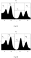
- Figures 3A and 3B do not in themselves fall under the claimed subject matter of the invention. They illustrate an example of an evaluation of a deviation between a measurement spectrum 310, 320 and a comparison pattern, which defines several wavelength-dependent comparison intensities 301, 302, 303, 304.
- the comparison intensities 301, 302, 303, 304 include a first comparison intensity 301 in a first wavelength range R1, a second comparison intensity 302 in a second wavelength range R2, a third comparison intensity 303 in a third wavelength range R3 and a fourth comparison intensity 304 in a fourth wavelength range R4, which differ from each other.
- the comparison intensities 301, 302, 303, 304 each correspond to a maximum intensity, exceeding which is classified as a deviation from the comparison pattern.
- a corresponding maximum intensity can be determined, for example, by evaluating measurement spectra classified as inconspicuous by determining the maximum observed intensity value of the measurement spectra classified as inconspicuous in the respective wavelength range R1, R2, R3, R4.
- the intensity values of the measurement spectrum 310 do not exceed the comparison intensities 301, 302, 303, 304 in any of the wavelength ranges R1, R2, R3, R4. In this case, no deviation from the comparison pattern is detected and the gas quality warning QW is not generated.
- the intensity values of the measurement spectrum 320 exceed the corresponding comparison intensity 303 in the wavelength range R3. In this case, a deviation from the comparison pattern is determined and the gas quality warning QW is generated.
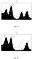
- Figures 4A and 4B do not in themselves fall under the claimed subject matter of the invention. They illustrate a further example of an evaluation of a deviation between a measurement spectrum 410, 420 and a comparison pattern, which has several wavelength-dependent comparison intensities 401, 402.
- the comparison intensities 401 include a first wavelength-dependent comparison intensity curve 401 and a second wavelength-dependent comparison intensity curve 402.
- the first comparison intensity curve 401 corresponds to a wavelength-dependent maximum intensity, exceeding which is classified as a deviation from the comparison pattern.
- the second comparison intensity curve 402 corresponds to a wavelength-dependent minimum intensity, Falling below this is classified as a deviation from the comparison sample.
- the wavelength-dependent comparison intensity profile 401 can be determined, for example, by evaluating measurement spectra classified as inconspicuous by determining an upper envelope of the measurement spectra classified as inconspicuous.
- the wavelength-dependent comparison intensity profile 402 can be determined, for example, by evaluating measurement spectra classified as inconspicuous by determining a lower envelope of the measurement spectra classified as inconspicuous.
- the intensity values of the measurement spectrum 410 do not exceed the comparison intensity curve 401 at any wavelength ⁇ . Furthermore, the intensity values of the measurement spectrum 410 do not fall below the comparison intensity curve 402 at any wavelength ⁇ either. In this case, no deviation from the comparison pattern is detected and the gas quality warning QW is not generated.
- the intensity values of the measurement spectrum 420 exceed the comparison intensity curve 401 in an area marked with A and fall below the comparison intensity curve 402 in an area marked with B. In this case, a deviation from the comparison pattern is determined and the gas quality warning QW is generated.
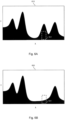
- Figures 5A and 5B illustrate an example of an evaluation of a deviation between a measurement spectrum 510, 520 and a comparison sample.
- This example takes advantage of the fact that the measurement spectrum 510, 520 is shown as an image, which is divided into a first area and a second area by the intensity curve of the measurement spectrum 510, 520.
- the first area is shown as a dark area.
- the second area is shown as a light area above the dark area.
- the comparison of the measurement spectrum with the comparison sample can be made using the image with the two areas.
- image analysis techniques can be used here.
- the comparison pattern has comparison areas 501, 502, 503.
- the comparison areas 501, 502, 503 can be, for example, by evaluating as Measurement spectra classified as inconspicuous can be determined by recording areas in images corresponding to these measurement spectra that are part of the brightly displayed second area in all images. It goes without saying that the comparison areas 501, 502, 503 do not necessarily have to have a rectangular shape, as shown in Figures 5A and 5B is shown, but also other shapes of the comparison areas can be used, for example a triangular shape, irregular polygons or shapes with curved boundaries. Furthermore, it is understood that one or more comparison areas could also be defined for the brightly displayed second area of the image, for which it is recorded whether there is an overlap with the second area of the image.
- Figures 6A and 6B illustrate another example of an evaluation of a deviation between a measurement spectrum 610, 620 and a comparison sample. Similar to the example of Figures 5A and 5B In this example, the measurement spectrum 610, 620 is shown as an image, which is divided into a first area and a second area by the intensity curve of the measurement spectrum 610, 620. In Figures 6A and 6B the first area is shown as a dark area. The second area is shown as a light area above the dark area. Similar to the example of Figures 5A and 5B In this case, too, the comparison of the measurement spectrum with the comparison sample can be carried out using the image with the two areas, for example using image analysis techniques. In the example of Figures 6A and 6B The comparison pattern defines a comparison area 601.
- a lack of complete overlap of the darkly displayed first area with this comparison area 601 is classified as a deviation from the comparison pattern.
- the comparison area 601 can be determined, for example, by evaluating measurement spectra that are classified as inconspicuous by detecting areas in images corresponding to these measurement spectra that are part of the first area shown dark in all images.
- the comparison area 601 does not necessarily have to have a rectangular shape, as shown in Figures 6A and 6B is shown, but also other shapes that can be used, for example a triangular shape, irregular polygons or shapes with curved boundary.
- one or more comparison areas could also be defined for the brightly displayed second area of the image, for which it is recorded whether an overlap with the second area of the image is complete.
- the intensity can be determined based on a maximum difference between the intensity values of the measurement spectrum and the comparison intensity.
- the strength of the deviation can be determined based on an area of the comparison region which is overlapped by the first region of the measurement spectrum.
- the gas quality warning QW can be generated depending on the strength of the deviation. For example, the gas quality warning QW can be generated when the magnitude of the deviation exceeds a threshold value.
- the gas quality warning QW can also be generated in multiple stages. For example, a first stage of the gas quality warning QW could be generated if the magnitude of the deviation exceeds a first threshold, and a second stage of the gas quality warning QW could be generated if the magnitude of the deviation exceeds a second threshold. Depending on the multi-stage gas quality warning QW, different automated control processes can then be initiated.
- the comparison samples used can be selected depending on the desired type of gas quality monitoring. For example, contamination of the gas sample can be detected efficiently via comparison patterns with maximum intensities, such as the comparison intensities 301, 302, 303, 304 or the comparison intensity profile 401, or via comparison areas with an impermissible overlap, such as the comparison areas 501, 502, 503 become. Such contamination can, for example, correspond to pollutants or undesirable odors in an air sample.
- an undesirable composition of components of the gas sample can be efficiently detected via comparison patterns with minimum intensities, such as the comparison intensity curve 401, via comparison patterns with maximum intensities, such as the comparison intensities 301, 302, 303, 304 or the comparison intensity curve 401, via comparison areas with an impermissible overlap , such as the comparison areas 501, 502, 503, or via comparison areas with a required overlap, such as the comparison areas 601.
- Such an undesirable composition of components of the gas sample can correspond, for example, to a concentration of a component of a process gas that is too low or to an oxygen content of air that is too low.
- the measurement spectra typically vary depending on temperature, pressure or air pressure and moisture content or humidity in the room to be monitored.
- the measurement spectra can again depend on the temperature or pressure of the process gas. These dependencies can be taken into account when evaluating the measurement spectra by detecting one or more of the environmental parameters and selecting the comparison pattern or patterns used for comparison depending on the detected environmental parameter. For example, different comparison patterns can be used at high temperatures than at low temperatures.
- the detection of the environmental parameter or parameters can take place via a corresponding sensor system, e.g. a temperature sensor, a pressure sensor or an air humidity sensor.
- the environmental parameters can be taken into account by recording and measuring one or more reference lines in the measurement spectra.
- reference lines can be generated specifically via the radiation source 110 of the spectrometer device 100 or a separate reference radiation source and/or with respect to intensity or wavelength be varied. From a known variation of the reference line(s) depending on the environmental parameter(s), conclusions can then be drawn about the environmental parameter(s).
- the reference lines can also be used to make a correction to the recorded measurement spectra, via which influences in the measurement spectra caused by variable environmental parameters are compensated for.
- Fig. 7 shows a flowchart to illustrate a method for gas quality monitoring according to an exemplary embodiment of the invention. The method can be carried out, for example, using the gas quality monitoring device explained above.
- At step 710 at least one comparison pattern is determined.
- the at least one comparison pattern can be selected from a large number of comparison patterns depending on one or more environmental parameters, for example depending on temperature, pressure, humidity, or the like.
- the at least one comparison pattern can, for example, have been determined based on measurement spectra that are classified as inconspicuous. For example, a large number of measurement spectra can be recorded under different environmental conditions and each operator can classify them as inconspicuous if there is no suspicion of poor gas quality in the gas sample being examined. For this purpose, additional tests can also be carried out using other analytical systems.
- a machine-based learning algorithm can also be used here, e.g. based on an artificial neural network (ANN).
- ANN artificial neural network
- comparison patterns can also be learned during operation. For example, if gas quality monitoring is carried out in conjunction with a ventilation system for a vehicle, feedback from a vehicle occupant as to whether an odor nuisance was perceived could be recorded and used as the basis for classifying a measurement spectrum recorded at this time as unremarkable.
- a gas sample from a room to be monitored is examined spectroscopically.
- the spectroscopic examination can be carried out in particular by Raman spectroscopy.
- the room to be monitored can be an interior of a vehicle or building or an air supply section of a ventilation system. However, in some scenarios the gas sample could also be taken outdoors.
- the room to be monitored can be a supply section for a process gas, a process room of the process system, or an exhaust gas section of the process system.
- the spectroscopic examination of the gas sample provides a measurement spectrum, such as one of the above-mentioned measurement spectra 200, 310, 320, 410, 420, 510, 520, 610, 620.
- the measurement spectrum typically shows a wavelength-dependent intensity curve.
- the measurement spectrum is displayed as an image which is divided into a first area and a second area by the wavelength-dependent intensity curve, as is the case, for example, in connection with Figs. 5A, 5B , 6A and 6B was explained.
- a deviation between the measurement spectrum and the at least one comparison pattern is detected.
- the deviation can be detected by comparing a wavelength-dependent intensity of the measurement spectrum with at least one comparison intensity defined by the comparison pattern.
- the measurement spectrum is displayed in the form of an image, which is divided into a first area and a second area depending on a wavelength-dependent intensity. The deviation occurs by detecting an overlap of the first area and/or the second area with at least one comparison area defined by the comparison pattern.
- a strength of the deviation between the measurement spectrum and the at least one comparison pattern can also be recorded.
- the strength can be quantified, for example, by a numerical value, which enables comparison with one or more threshold values.
- step 740 a check is made as to whether a deviation was detected in step 730 or whether the deviation detected in step 730 has a certain minimum strength. The latter can be done, for example, by comparing the strength of the deviation with a threshold value. If so, the process continues with step 750, as indicated by branch "J". Otherwise, the process may return to steps 710 as indicated by branch "N".
- a gas quality alert is generated.
- the gas quality warning indicates that there is a risk of poor quality of a gas from which the gas sample examined in step 720 was taken.
- the gas quality warning can be generated as a visual and/or acoustic signal.
- the gas quality warning can also be generated as an electronic signal.
- the gas quality warning can also depend on a The strength of the deviation between the measurement spectrum and the at least one comparison pattern recorded in step 730 can be generated.
- the gas quality alert may be generated in a multi-level manner by comparing the magnitude of the deviation to one or more threshold values.
- a first level of gas quality warning could be generated when the magnitude of the deviation exceeds a first threshold
- a second stage of gas quality warning could be generated when the magnitude of the deviation exceeds a higher second threshold.
- a gas delivery device may then be controlled depending on the gas quality warning generated at step 750.
- gas delivery can be stopped in response to the gas quality warning, for example by closing valves or flaps and/or deactivating a pump or fan.
- measures to improve the gas quality can be initiated, for example by venting the room to be monitored.
- a machine-based learning algorithm can be used to learn the comparison patterns, for example based on an ANN.
- the machine-based learning algorithm can be trained using pre-classified measurement spectra and/or during operation. In the latter case, for example, an operator can provide feedback to the learning algorithm as to whether a generated gas quality warning was accurate or not.
- a training measurement system based on additional sensors and/or analytics, which specifically identifies problematic gas compositions, can also be used to train the machine-based learning algorithm and to learn the comparison patterns.
- Such a training measuring system could only be used for training purposes, for example during initial commissioning, calibration or other preconfiguration of the gas quality monitoring device. Therefore, the training measurement system could be based on more sophisticated sensor technology than the gas quality monitoring device.
- comparison patterns can be determined in advance by the machine-based learning algorithm for a variety of gas quality monitoring devices, and the learning results obtained from one device can be transferred to other devices.
- Fig. 8 illustrates an example of a scenario in which the gas quality monitoring described above is used in a ventilation system.
- Special shows Fig. 8 a motor vehicle 800, which has a ventilation system 850, which can be part of an air conditioning system, for example.
- this scenario can also easily be transferred to a ventilation system in another type of vehicle, for example an airplane, a watercraft or a rail vehicle.
- the ventilation system 850 has an air supply section 870, via which air is taken into the ventilation system 850 from outside and then fed into an interior 810 of the motor vehicle 800 via an air delivery system 860.
- the air delivery system 860 can, for example, be based on a fan and also have one or more flaps through which the supply of air from outside can be prevented. The latter is desirable, for example, if unpleasant smells occur in the area around the motor vehicle 800 or if the motor vehicle 800 is in a tunnel or a garage.
- the gas quality warning can be used to control the air delivery system 860.
- the doors of the air delivery system 860 may be closed to prevent poor quality air from being introduced into the vehicle interior 810.
- the gas samples can also be taken from the interior 810 of the motor vehicle 800.
- the air delivery system 860 in response to the gas quality warning, may be caused to increase the supply of air from the outside into the interior 810 of the vehicle 800 so as to improve the quality of the air in the interior 810.
- the gas quality warning can also be displayed to the driver or other occupants of the motor vehicle 800 in the form of a visual or acoustic signal.
- an air purification function of the ventilation system 850 can also be activated. Such an air purification function can be based on a filter device, for example.
- Fig. 9 illustrates an example of a scenario using the gas quality monitoring described above in a process plant 900.
- the process system can be used, for example, to manufacture or process products.
- products could be treated with one or more process gases.
- a chemical reaction of one or more process gases could also take place in the process system, for example as part of combustion.
- the process system 900 has a process room 910 in which
- Process gases are supplied from a first gas source 921 and from a second gas source 922.
- the process gases are supplied via supply lines 941, 942, which are provided with controllable valves 951, 952.
- the process system 900 also has an exhaust gas line 943, via which exhaust gases generated during the processes in the process space 910 can be removed.
- the exhaust line 943 is also provided with a controllable valve 953.
- the valves 951,900 52,953 are controlled via a valve control 960.
- the supply lines 941,942, the exhaust line 943, the valves 951, 952,953, and the valve control 960 form a gas delivery system of the process plant 900.
- the gas quality warning can be used to control the gas delivery system of the process plant 900.
- the valves 951, 952 may be closed to avoid introducing poor quality process gas into the process space 910.
- gas samples can also be taken from the process room 910.
- the valve 943 may be caused to be opened to remove poor quality gases from the process space 910.
- a gas cleaning function of the process system 900 can also be activated. Such a gas cleaning function can be based, for example, on a chemical reaction in the process space 910. Alternatively or additionally, gas cleaning can also be based on filtering.
- the gas quality warning can be displayed to an operator of the process plant 900 in the form of a visual or acoustic signal or can be used as a trigger for an automatic safety shutdown of the process plant 900.
- gas quality monitoring described is not limited to ventilation systems or process systems, but could also be used in a variety of other areas.
- comparison patterns described herein can be modified or combined in various ways to generate new types of comparison patterns.
- Raman spectroscopy other spectroscopic methods could also be used, e.g. infrared spectroscopy.
Landscapes
- Engineering & Computer Science (AREA)
- Physics & Mathematics (AREA)
- Health & Medical Sciences (AREA)
- Life Sciences & Earth Sciences (AREA)
- Chemical & Material Sciences (AREA)
- General Health & Medical Sciences (AREA)
- General Physics & Mathematics (AREA)
- Theoretical Computer Science (AREA)
- General Engineering & Computer Science (AREA)
- Mathematical Physics (AREA)
- Biochemistry (AREA)
- Pathology (AREA)
- Immunology (AREA)
- Analytical Chemistry (AREA)
- Data Mining & Analysis (AREA)
- Artificial Intelligence (AREA)
- Biophysics (AREA)
- Evolutionary Computation (AREA)
- Molecular Biology (AREA)
- Computing Systems (AREA)
- Biomedical Technology (AREA)
- Computational Linguistics (AREA)
- Software Systems (AREA)
- Combustion & Propulsion (AREA)
- Mechanical Engineering (AREA)
- Food Science & Technology (AREA)
- Medicinal Chemistry (AREA)
- Signal Processing (AREA)
- Nuclear Medicine, Radiotherapy & Molecular Imaging (AREA)
- Thermal Sciences (AREA)
- Fuzzy Systems (AREA)
- Investigating Or Analysing Materials By Optical Means (AREA)
- Investigating, Analyzing Materials By Fluorescence Or Luminescence (AREA)
Claims (14)
- Procédé de surveillance de la qualité d'un gaz, ledit procédé comprenant les étapes suivantes :- effectuer une analyse spectroscopique d'un échantillon de gaz provenant d'un espace à surveiller, l'analyse spectroscopique fournissant un spectre de mesure (510, 520, 610, 620) qui s'étend dans une gamme de longueurs d'onde ;- représenter le spectre de mesure (510, 520, 610, 620) sous la forme d'une image qui est divisée en une première zone et une deuxième zone, l'intensité mesurée dépendant de la longueur d'onde séparant la première zone de la deuxième zone ;- détecter un écart entre le spectre de mesure (510, 520, 610, 620) et au moins un modèle de comparaison (160) sur la base de l'image par détection d'un chevauchement de la première zone et/ou de la deuxième zone avec au moins une zone de comparaison (501, 502, 503 ; 601) défini par le modèle de comparaison (160) ; et- générer un avertissement de qualité de gaz (GW) en fonction de l'écart détecté.
- Procédé selon la revendication 1, comprenant :- détecter au moins un paramètre d'environnement de l'espace à surveiller (10) ; et- sélectionner l'au moins un modèle de comparaison (160) en fonction de l'au moins un paramètre d'environnement détecté.
- Procédé selon la revendication 2,
l'au moins un paramètre d'environnement comprenant une température, une pression et/ou une teneur en humidité. - Procédé selon l'une des revendications précédentes, comprenant les étapes suivantes :- effectuer une détection supplémentaire de l'écart par comparaison d'une intensité dépendante de la longueur d'onde du spectre de mesure (310, 320 ; 410, 420) à au moins une intensité de comparaison (301, 302, 303, 304 ; 401, 402) définie par le modèle de comparaison (160).
- Procédé selon l'une des revendications précédentes, comprenant les étapes suivantes :- détecter une ampleur de l'écart ; et- générer l'avertissement de qualité de gaz (QW) en fonction de l'ampleur de l'écart détectée.
- Procédé selon l'une des revendications précédentes,
l'au moins un modèle de comparaison (160) décrivant des propriétés communes de spectres de mesure classés comme non suspects. - Procédé selon l'une des revendications précédentes,
l'analyse spectroscopique de l'échantillon de gaz étant effectuée par spectroscopie Raman. - Procédé selon l'une des revendications précédentes, comprenant les étapes suivantes :- déterminer l'au moins un modèle de comparaison par entraînement d'un algorithme d'apprentissage par machine.
- Procédé selon l'une des revendications précédentes, comprenant l'étape suivante :- en fonction de l'avertissement de qualité de gaz (QW) généré, commander un dispositif de transport de gaz jusque dans l'espace à surveiller (10) et/ou depuis celui-ci.
- Procédé selon la revendication 9,le dispositif comprenant une installation de ventilation (850) et l'espace à surveiller étant situé dans une portion d'alimentation en air (870) de l'installation de ventilation (850) ou dans un espace (810) à ventiler par le biais de l'installation de ventilation (850), oule dispositif comprenant une installation de traitement (900) et l'espace à surveiller étant situé dans une portion d'alimentation (941, 942) destinée à un gaz de traitement utilisé dans l'installation de traitement (900) ou étant situé dans un espace de traitement (910) de l'installation de traitement (900).
- Dispositif de surveillance de la qualité d'un gaz, ledit dispositif comprenant :
un module de spectrométrie (100) destiné à effectuer l'analyse spectroscopique d'un échantillon de gaz provenant d'un espace à surveiller (10), l'analyse spectroscopique fournissant un spectre de mesure (510, 520 ; 610, 620) qui s'étend dans une gamme de longueurs d'onde ; et- un module d'évaluation (150) qui est conçu pour :- représenter le spectre de mesure (510, 520, 610, 620) sous la forme d'une image qui est divisée en une première zone et une deuxième zone, l'intensité mesurée dépendant de la longueur d'onde séparant la première zone de la deuxième zone ;- détecter un écart entre le spectre de mesure (510, 520, 610, 620) et l'au moins un modèle de comparaison (160) sur la base de l'image par détection d'un chevauchement de la première zone et/ou de la deuxième zone avec au moins une zone de comparaison (501, 502, 503 ; 601) définie par le modèle de comparaison (160) ; et- générer un avertissement de qualité de gaz (QW) en fonction de l'écart détecté. - Dispositif selon la revendication 11,
le dispositif étant conçu pour mettre en œuvre un procédé selon l'une des revendications 1 à 10. - Installation de ventilation (850) comprenant :un dispositif (860) destiné à transporter de l'air jusque dans un espace à ventiler (810) et/ou depuis l'espace à ventiler (810) ; etun dispositif de surveillance de la qualité d'un gaz selon l'une des revendications 11 et 12,l'espace à surveiller (810) étant situé dans une portion d'alimentation en air (870) de l'installation de ventilation (850) ou dans l'espace à ventiler(810), etle dispositif (860) destiné à transporter de l'air étant commandé en fonction de l'avertissement de qualité de gaz.
- Installation de traitement (900) comprenant :un dispositif (941, 942, 943, 951, 952, 953, 960) destiné à transporter du gaz jusque dans un espace de traitement (910) de l'installation de traitement (900) et/ou depuis l'espace de traitement (910) de l'installation de traitement (900) ; etun dispositif de surveillance de la qualité d'un gaz selon la revendication 11 ou 12,l'espace à surveiller étant situé dans une portion d'alimentation (941, 942) destinée à un gaz de traitement utilisé dans l'installation de traitement (900) ou étant situé dans l'espace de traitement (910) de l'installation de traitement (900), etle dispositif (941, 942, 943, 951, 952, 953, 960) étant commandé pour transporter un gaz en fonction de l'avertissement de qualité de gaz.
Applications Claiming Priority (2)
| Application Number | Priority Date | Filing Date | Title |
|---|---|---|---|
| DE102017117709.4A DE102017117709A1 (de) | 2017-08-04 | 2017-08-04 | Musterbasierte spektroskopische Gasqualitätsüberwachung |
| PCT/EP2018/071047 WO2019025564A1 (fr) | 2017-08-04 | 2018-08-02 | Surveillance de la qualité d'un gaz à base de motif par spectroscopie raman |
Publications (3)
| Publication Number | Publication Date |
|---|---|
| EP3662262A1 EP3662262A1 (fr) | 2020-06-10 |
| EP3662262C0 EP3662262C0 (fr) | 2023-11-15 |
| EP3662262B1 true EP3662262B1 (fr) | 2023-11-15 |
Family
ID=63113535
Family Applications (1)
| Application Number | Title | Priority Date | Filing Date |
|---|---|---|---|
| EP18750410.5A Active EP3662262B1 (fr) | 2017-08-04 | 2018-08-02 | Surveillance de la qualité du gaz basé sur un motif par spectroscopie |
Country Status (5)
| Country | Link |
|---|---|
| US (1) | US11460407B2 (fr) |
| EP (1) | EP3662262B1 (fr) |
| CN (1) | CN110998289B (fr) |
| DE (1) | DE102017117709A1 (fr) |
| WO (1) | WO2019025564A1 (fr) |
Families Citing this family (3)
| Publication number | Priority date | Publication date | Assignee | Title |
|---|---|---|---|---|
| US12562240B2 (en) * | 2020-11-13 | 2026-02-24 | Wynd Technologies, Inc. | Pollution type sensing |
| CN114441505B (zh) * | 2022-03-17 | 2023-08-18 | 中国工程物理研究院机械制造工艺研究所 | 一种用于拉曼探头的水汽原位标定装置、标定方法及应用 |
| EP4567409A1 (fr) | 2023-12-07 | 2025-06-11 | Sensing Solutions, S.L. | Dispositif de surveillance, système et procédé de détection d'un élément dans un fluide |
Family Cites Families (30)
| Publication number | Priority date | Publication date | Assignee | Title |
|---|---|---|---|---|
| US3768908A (en) * | 1971-01-04 | 1973-10-30 | S Zaromb | Remote sensing apparatus and methods |
| DE19518598A1 (de) | 1995-05-20 | 1996-11-21 | Zeiss Carl Jena Gmbh | Anordnung und Verfahren zur Auswertung der von einem induktiv gekoppelten Plasma emittierten Spektrallinien |
| DE19528960C2 (de) | 1995-08-08 | 1997-07-17 | Eltro Gmbh | Verfahren und Einrichtung zur Fernmessung von Luftschadstoffen |
| DE19615365A1 (de) | 1996-04-19 | 1997-10-23 | Zeiss Carl Jena Gmbh | Optische Anordnung zur Raman-Spektralanalyse |
| US5866430A (en) * | 1996-06-13 | 1999-02-02 | Grow; Ann E. | Raman optrode processes and devices for detection of chemicals and microorganisms |
| US6134004A (en) | 1996-07-10 | 2000-10-17 | 3M Innovative Properties Company | Open air optical analysis apparatus and method regarding same |
| CN1105296C (zh) * | 1996-08-22 | 2003-04-09 | 伊斯曼化学公司 | 定量监测化学组合物的组份的方法 |
| US6439040B1 (en) | 1997-08-25 | 2002-08-27 | Wissenschaftliche Wekstatt Fur Umweltmesstechnik Gmbh | Device for analyzing exhaust emissions from motor vehicles |
| DE19743954C2 (de) | 1997-10-04 | 2000-10-12 | Wwu Wissenschaftliche Werkstat | Kaltstartmeßsytem zur Messung der Kaltstartemission |
| JP2000314684A (ja) | 1999-04-16 | 2000-11-14 | Sensors Inc | 車両用質量排出量測定 |
| US7002678B1 (en) * | 1999-08-28 | 2006-02-21 | Koninklijke Philips Electronics N.V. | Avoidance of poisoning during anesthesia |
| DE19949439C1 (de) * | 1999-10-14 | 2001-02-08 | Flow Comp Systemtechnik Gmbh | Gasqualitätsbestimmung |
| US6952945B2 (en) | 2000-01-25 | 2005-10-11 | The State Of Oregon Acting By And Through The State Board Of Higher Education On Behalf Of Portland State University | Method and apparatus for concentrating samples for analysis |
| US7591980B2 (en) * | 2004-03-01 | 2009-09-22 | Mesosystems Technology, Inc. | Biological alarm |
| US7116415B2 (en) * | 2004-06-18 | 2006-10-03 | In Technology Holding Llc | Method and apparatus for detecting chemical and biological weapon components using Raman spectrum |
| US7372573B2 (en) | 2005-09-30 | 2008-05-13 | Mks Instruments, Inc. | Multigas monitoring and detection system |
| US20110208462A1 (en) * | 2007-07-31 | 2011-08-25 | Chemimage Corporation | System and method for instrument correction using transmission efficiency |
| US7835873B2 (en) * | 2008-03-28 | 2010-11-16 | The Boeing Company | Method and system for monitoring changes in a sample for a process or an environment |
| TWM422070U (en) | 2011-03-03 | 2012-02-01 | Data Test Scient Co Ltd | A real-time and energy-efficient micro gas analyzer |
| US10702187B2 (en) * | 2011-04-26 | 2020-07-07 | Koninklijke Philips N.V. | Apparatus and method for controlling radiation source variability for optical gas measurement systems |
| US10859474B2 (en) | 2013-02-28 | 2020-12-08 | TricornTech Taiwan | Real-time on-site gas analysis network for ambient air monitoring and active control and response |
| CN104459058B (zh) | 2013-04-17 | 2016-03-02 | 王金松 | 汽车车内气体分析装置 |
| CN103411952B (zh) * | 2013-08-08 | 2015-11-18 | 浙江大学 | 一种基于拉曼光谱技术的藻种分类识别方法 |
| EP2857811B1 (fr) | 2013-10-02 | 2015-09-23 | Sick Ag | Spectromètre pour l'analyse de gaz |
| US10643008B2 (en) * | 2014-11-11 | 2020-05-05 | Spectrasensors, Inc. | Target analyte detection and quantification in sample gases with complex background compositions |
| TWM500247U (zh) | 2014-11-26 | 2015-05-01 | Coasia Microelectronics Corp | 行動空氣品質偵測系統及其環境空氣偵測裝置 |
| DE102015103484A1 (de) * | 2015-03-10 | 2016-09-15 | Endress + Hauser Conducta Gesellschaft für Mess- und Regeltechnik mbH + Co. KG | In-Line-Messeinrichtung |
| CN204666187U (zh) | 2015-04-08 | 2015-09-23 | 黄斌 | 一种手术室空气检测系统 |
| CN105806825B (zh) * | 2016-05-17 | 2019-07-23 | 浙江大学 | 一种天然气组分在线气体拉曼分析方法 |
| CA3041100A1 (fr) * | 2016-10-21 | 2018-04-26 | Rebellion Photonics, Inc. | Systeme d'imagerie a gaz |
-
2017
- 2017-08-04 DE DE102017117709.4A patent/DE102017117709A1/de active Pending
-
2018
- 2018-08-02 WO PCT/EP2018/071047 patent/WO2019025564A1/fr not_active Ceased
- 2018-08-02 CN CN201880050514.4A patent/CN110998289B/zh active Active
- 2018-08-02 US US16/636,281 patent/US11460407B2/en active Active
- 2018-08-02 EP EP18750410.5A patent/EP3662262B1/fr active Active
Also Published As
| Publication number | Publication date |
|---|---|
| CN110998289A (zh) | 2020-04-10 |
| WO2019025564A1 (fr) | 2019-02-07 |
| EP3662262A1 (fr) | 2020-06-10 |
| CN110998289B (zh) | 2024-03-01 |
| US11460407B2 (en) | 2022-10-04 |
| EP3662262C0 (fr) | 2023-11-15 |
| DE102017117709A1 (de) | 2019-02-21 |
| US20210164907A1 (en) | 2021-06-03 |
Similar Documents
| Publication | Publication Date | Title |
|---|---|---|
| EP3662262B1 (fr) | Surveillance de la qualité du gaz basé sur un motif par spectroscopie | |
| EP2284518A1 (fr) | Procédé de détermination d'un paramètre, notamment du besoin en oxygène chimique (CSB), de la teneur totale en carbone organique (TOC) ou de la concentration d'un ou de plusieurs composants d'un échantillon de liquide | |
| EP2748589B1 (fr) | Méthode pour déterminer la pureté d'un réfrigérant | |
| DE102018111264B4 (de) | System zum reduzieren von flüchtigen organischen verbindungen in einem fahrzeug | |
| EP1406048A3 (fr) | Dispositif de surveillance de la pollution de l'air de locaux | |
| EP3842788B1 (fr) | Capteur spectral proche infrarouge de reconnaissance d'objets utilisant des méthodes d'apprentissage automatique, et méthode correspondante | |
| DE102018109819A1 (de) | Verfahren zur Gewinnung von Information aus Röntgen-Computertomographiedaten zur Optimierung des Spritzgussprozesses von kurzfaserverstärkten Kunststoffteilen | |
| DE102018200003A1 (de) | Verfahren zur Atemanalyse von Fahrzeuginsassen | |
| DE102018203858A1 (de) | Verfahren zum Anpassen von Feinstaubmesswerten | |
| DE112021006716T5 (de) | System und Verfahren zum Überwachen und Steuern der Luftqualität in einem Fahrzeugraum | |
| EP1654132B1 (fr) | Procede de regulation de la proportion d'air de circulation et/ou d'air frais dans un habitacle | |
| DE202006020449U1 (de) | Vorrichtung zur Bestimmung der Oberflächenfeuchte eines Messobjekts | |
| EP4058783A1 (fr) | Commande de processus en boucle ouverte/boucle fermée sur la base d'une détermination spectroscopique de concentrations de substances non déterminées | |
| WO2017009158A1 (fr) | Procédé de réglage d'un processus de combustion | |
| DE69902360T2 (de) | Stochastische arrayverarbeitung von sensormessungen zur detektion und zahlenmässiger auswertung von analyten | |
| EP4127656B1 (fr) | Procédé et dispositif de mesure d'aérosol pour déterminer une distribution granulométrique basée sur une source d'un aérosol | |
| DE102022130510A1 (de) | Überwachungsverfahren zur Qualitätsüberwachung von Messspektren | |
| EP3771900B1 (fr) | Procédé de détermination d'une concentration en gaz et appareil de mesure | |
| EP4075067A1 (fr) | Procédé et système de détermination d'un moment de remplacement d'un filtre à odeurs et hotte aspirante | |
| DE102007019790B4 (de) | Verfahren und Vorrichtung zur Charakterisierung einer Pflanzenprobe | |
| DE3722983A1 (de) | Sensorgefuehrtes umd microprozessorgesteuertes erfassungs- und regelsystem zur bekaempfung von geruechen bei verbrennungen, verkokungen, vergasungen und bei biologischen umsetzprozessen | |
| WO2001035075A2 (fr) | Procede d'evaluation de spectres electromagnetiques de substances pour determiner leur effet propre a une application avec des methodes relevant de la reconnaissance de formes | |
| DE102018104726A1 (de) | Sensoranordnung für ein Kraftfahrzeug | |
| DE102009054284A1 (de) | Vorrichtung und Verfahren zur Prozesskontrolle bei der Schaumstoffproduktion mittels Gasphasen-Analyse | |
| WO2023209117A1 (fr) | Procédé de détermination, de différenciation et/ou d'influence d'au moins un cov ou d'au moins une autre substance |
Legal Events
| Date | Code | Title | Description |
|---|---|---|---|
| STAA | Information on the status of an ep patent application or granted ep patent |
Free format text: STATUS: UNKNOWN |
|
| STAA | Information on the status of an ep patent application or granted ep patent |
Free format text: STATUS: THE INTERNATIONAL PUBLICATION HAS BEEN MADE |
|
| PUAI | Public reference made under article 153(3) epc to a published international application that has entered the european phase |
Free format text: ORIGINAL CODE: 0009012 |
|
| STAA | Information on the status of an ep patent application or granted ep patent |
Free format text: STATUS: REQUEST FOR EXAMINATION WAS MADE |
|
| 17P | Request for examination filed |
Effective date: 20200302 |
|
| AK | Designated contracting states |
Kind code of ref document: A1 Designated state(s): AL AT BE BG CH CY CZ DE DK EE ES FI FR GB GR HR HU IE IS IT LI LT LU LV MC MK MT NL NO PL PT RO RS SE SI SK SM TR |
|
| AX | Request for extension of the european patent |
Extension state: BA ME |
|
| DAV | Request for validation of the european patent (deleted) | ||
| DAX | Request for extension of the european patent (deleted) | ||
| STAA | Information on the status of an ep patent application or granted ep patent |
Free format text: STATUS: EXAMINATION IS IN PROGRESS |
|
| 17Q | First examination report despatched |
Effective date: 20211208 |
|
| GRAP | Despatch of communication of intention to grant a patent |
Free format text: ORIGINAL CODE: EPIDOSNIGR1 |
|
| STAA | Information on the status of an ep patent application or granted ep patent |
Free format text: STATUS: GRANT OF PATENT IS INTENDED |
|
| INTG | Intention to grant announced |
Effective date: 20230207 |
|
| GRAJ | Information related to disapproval of communication of intention to grant by the applicant or resumption of examination proceedings by the epo deleted |
Free format text: ORIGINAL CODE: EPIDOSDIGR1 |
|
| STAA | Information on the status of an ep patent application or granted ep patent |
Free format text: STATUS: EXAMINATION IS IN PROGRESS |
|
| GRAP | Despatch of communication of intention to grant a patent |
Free format text: ORIGINAL CODE: EPIDOSNIGR1 |
|
| STAA | Information on the status of an ep patent application or granted ep patent |
Free format text: STATUS: GRANT OF PATENT IS INTENDED |
|
| INTC | Intention to grant announced (deleted) | ||
| INTG | Intention to grant announced |
Effective date: 20230703 |
|
| RIN1 | Information on inventor provided before grant (corrected) |
Inventor name: HELGERT, MICHAEL Inventor name: DEPARNAY, ARNAUD Inventor name: GATTO, ALEXANDRE Inventor name: RODE, MICHAEL |
|
| GRAS | Grant fee paid |
Free format text: ORIGINAL CODE: EPIDOSNIGR3 |
|
| GRAA | (expected) grant |
Free format text: ORIGINAL CODE: 0009210 |
|
| STAA | Information on the status of an ep patent application or granted ep patent |
Free format text: STATUS: THE PATENT HAS BEEN GRANTED |
|
| AK | Designated contracting states |
Kind code of ref document: B1 Designated state(s): AL AT BE BG CH CY CZ DE DK EE ES FI FR GB GR HR HU IE IS IT LI LT LU LV MC MK MT NL NO PL PT RO RS SE SI SK SM TR |
|
| REG | Reference to a national code |
Ref country code: CH Ref legal event code: EP Ref country code: GB Ref legal event code: FG4D Free format text: NOT ENGLISH |
|
| REG | Reference to a national code |
Ref country code: DE Ref legal event code: R096 Ref document number: 502018013635 Country of ref document: DE |
|
| REG | Reference to a national code |
Ref country code: IE Ref legal event code: FG4D Free format text: LANGUAGE OF EP DOCUMENT: GERMAN |
|
| U01 | Request for unitary effect filed |
Effective date: 20231116 |
|
| U07 | Unitary effect registered |
Designated state(s): AT BE BG DE DK EE FI FR IT LT LU LV MT NL PT SE SI Effective date: 20231121 |
|
| U1N | Appointed representative for the unitary patent procedure changed after the registration of the unitary effect |
Representative=s name: KRAUS & WEISERT PATENTANWAELTE PARTGMBB; DE |
|
| PG25 | Lapsed in a contracting state [announced via postgrant information from national office to epo] |
Ref country code: GR Free format text: LAPSE BECAUSE OF FAILURE TO SUBMIT A TRANSLATION OF THE DESCRIPTION OR TO PAY THE FEE WITHIN THE PRESCRIBED TIME-LIMIT Effective date: 20240216 |
|
| PG25 | Lapsed in a contracting state [announced via postgrant information from national office to epo] |
Ref country code: IS Free format text: LAPSE BECAUSE OF FAILURE TO SUBMIT A TRANSLATION OF THE DESCRIPTION OR TO PAY THE FEE WITHIN THE PRESCRIBED TIME-LIMIT Effective date: 20240315 |
|
| PG25 | Lapsed in a contracting state [announced via postgrant information from national office to epo] |
Ref country code: ES Free format text: LAPSE BECAUSE OF FAILURE TO SUBMIT A TRANSLATION OF THE DESCRIPTION OR TO PAY THE FEE WITHIN THE PRESCRIBED TIME-LIMIT Effective date: 20231115 |
|
| PG25 | Lapsed in a contracting state [announced via postgrant information from national office to epo] |
Ref country code: IS Free format text: LAPSE BECAUSE OF FAILURE TO SUBMIT A TRANSLATION OF THE DESCRIPTION OR TO PAY THE FEE WITHIN THE PRESCRIBED TIME-LIMIT Effective date: 20240315 Ref country code: GR Free format text: LAPSE BECAUSE OF FAILURE TO SUBMIT A TRANSLATION OF THE DESCRIPTION OR TO PAY THE FEE WITHIN THE PRESCRIBED TIME-LIMIT Effective date: 20240216 Ref country code: ES Free format text: LAPSE BECAUSE OF FAILURE TO SUBMIT A TRANSLATION OF THE DESCRIPTION OR TO PAY THE FEE WITHIN THE PRESCRIBED TIME-LIMIT Effective date: 20231115 |
|
| PG25 | Lapsed in a contracting state [announced via postgrant information from national office to epo] |
Ref country code: RS Free format text: LAPSE BECAUSE OF FAILURE TO SUBMIT A TRANSLATION OF THE DESCRIPTION OR TO PAY THE FEE WITHIN THE PRESCRIBED TIME-LIMIT Effective date: 20231115 Ref country code: PL Free format text: LAPSE BECAUSE OF FAILURE TO SUBMIT A TRANSLATION OF THE DESCRIPTION OR TO PAY THE FEE WITHIN THE PRESCRIBED TIME-LIMIT Effective date: 20231115 Ref country code: NO Free format text: LAPSE BECAUSE OF FAILURE TO SUBMIT A TRANSLATION OF THE DESCRIPTION OR TO PAY THE FEE WITHIN THE PRESCRIBED TIME-LIMIT Effective date: 20240215 Ref country code: HR Free format text: LAPSE BECAUSE OF FAILURE TO SUBMIT A TRANSLATION OF THE DESCRIPTION OR TO PAY THE FEE WITHIN THE PRESCRIBED TIME-LIMIT Effective date: 20231115 |
|
| PG25 | Lapsed in a contracting state [announced via postgrant information from national office to epo] |
Ref country code: CZ Free format text: LAPSE BECAUSE OF FAILURE TO SUBMIT A TRANSLATION OF THE DESCRIPTION OR TO PAY THE FEE WITHIN THE PRESCRIBED TIME-LIMIT Effective date: 20231115 |
|
| PG25 | Lapsed in a contracting state [announced via postgrant information from national office to epo] |
Ref country code: SK Free format text: LAPSE BECAUSE OF FAILURE TO SUBMIT A TRANSLATION OF THE DESCRIPTION OR TO PAY THE FEE WITHIN THE PRESCRIBED TIME-LIMIT Effective date: 20231115 |
|
| PG25 | Lapsed in a contracting state [announced via postgrant information from national office to epo] |
Ref country code: SM Free format text: LAPSE BECAUSE OF FAILURE TO SUBMIT A TRANSLATION OF THE DESCRIPTION OR TO PAY THE FEE WITHIN THE PRESCRIBED TIME-LIMIT Effective date: 20231115 Ref country code: SK Free format text: LAPSE BECAUSE OF FAILURE TO SUBMIT A TRANSLATION OF THE DESCRIPTION OR TO PAY THE FEE WITHIN THE PRESCRIBED TIME-LIMIT Effective date: 20231115 Ref country code: RO Free format text: LAPSE BECAUSE OF FAILURE TO SUBMIT A TRANSLATION OF THE DESCRIPTION OR TO PAY THE FEE WITHIN THE PRESCRIBED TIME-LIMIT Effective date: 20231115 Ref country code: CZ Free format text: LAPSE BECAUSE OF FAILURE TO SUBMIT A TRANSLATION OF THE DESCRIPTION OR TO PAY THE FEE WITHIN THE PRESCRIBED TIME-LIMIT Effective date: 20231115 |
|
| REG | Reference to a national code |
Ref country code: DE Ref legal event code: R097 Ref document number: 502018013635 Country of ref document: DE |
|
| PLBE | No opposition filed within time limit |
Free format text: ORIGINAL CODE: 0009261 |
|
| STAA | Information on the status of an ep patent application or granted ep patent |
Free format text: STATUS: NO OPPOSITION FILED WITHIN TIME LIMIT |
|
| U20 | Renewal fee for the european patent with unitary effect paid |
Year of fee payment: 7 Effective date: 20240827 |
|
| 26N | No opposition filed |
Effective date: 20240819 |
|
| REG | Reference to a national code |
Ref country code: CH Ref legal event code: PL |
|
| GBPC | Gb: european patent ceased through non-payment of renewal fee |
Effective date: 20240802 |
|
| PG25 | Lapsed in a contracting state [announced via postgrant information from national office to epo] |
Ref country code: CH Free format text: LAPSE BECAUSE OF NON-PAYMENT OF DUE FEES Effective date: 20240831 Ref country code: MC Free format text: LAPSE BECAUSE OF FAILURE TO SUBMIT A TRANSLATION OF THE DESCRIPTION OR TO PAY THE FEE WITHIN THE PRESCRIBED TIME-LIMIT Effective date: 20231115 |
|
| PG25 | Lapsed in a contracting state [announced via postgrant information from national office to epo] |
Ref country code: GB Free format text: LAPSE BECAUSE OF NON-PAYMENT OF DUE FEES Effective date: 20240802 |
|
| PG25 | Lapsed in a contracting state [announced via postgrant information from national office to epo] |
Ref country code: IE Free format text: LAPSE BECAUSE OF NON-PAYMENT OF DUE FEES Effective date: 20240802 |
|
| U20 | Renewal fee for the european patent with unitary effect paid |
Year of fee payment: 8 Effective date: 20250827 |
|
| PG25 | Lapsed in a contracting state [announced via postgrant information from national office to epo] |
Ref country code: CY Free format text: LAPSE BECAUSE OF FAILURE TO SUBMIT A TRANSLATION OF THE DESCRIPTION OR TO PAY THE FEE WITHIN THE PRESCRIBED TIME-LIMIT; INVALID AB INITIO Effective date: 20180802 |
|
| PG25 | Lapsed in a contracting state [announced via postgrant information from national office to epo] |
Ref country code: HU Free format text: LAPSE BECAUSE OF FAILURE TO SUBMIT A TRANSLATION OF THE DESCRIPTION OR TO PAY THE FEE WITHIN THE PRESCRIBED TIME-LIMIT; INVALID AB INITIO Effective date: 20180802 |