EP3662346B1 - Dispositif de commande pour machines industrielles - Google Patents
Dispositif de commande pour machines industrielles Download PDFInfo
- Publication number
- EP3662346B1 EP3662346B1 EP18765536.0A EP18765536A EP3662346B1 EP 3662346 B1 EP3662346 B1 EP 3662346B1 EP 18765536 A EP18765536 A EP 18765536A EP 3662346 B1 EP3662346 B1 EP 3662346B1
- Authority
- EP
- European Patent Office
- Prior art keywords
- control device
- operating mode
- evaluation
- actuation member
- rotation
- Prior art date
- Legal status (The legal status is an assumption and is not a legal conclusion. Google has not performed a legal analysis and makes no representation as to the accuracy of the status listed.)
- Active
Links
Images


Classifications
-
- G—PHYSICS
- G05—CONTROLLING; REGULATING
- G05G—CONTROL DEVICES OR SYSTEMS INSOFAR AS CHARACTERISED BY MECHANICAL FEATURES ONLY
- G05G5/00—Means for preventing, limiting or returning the movements of parts of a control mechanism, e.g. locking controlling member
- G05G5/03—Means for enhancing the operator's awareness of arrival of the controlling member at a command or datum position; Providing feel, e.g. means for creating a counterforce
-
- G—PHYSICS
- G06—COMPUTING OR CALCULATING; COUNTING
- G06F—ELECTRIC DIGITAL DATA PROCESSING
- G06F3/00—Input arrangements for transferring data to be processed into a form capable of being handled by the computer; Output arrangements for transferring data from processing unit to output unit, e.g. interface arrangements
- G06F3/01—Input arrangements or combined input and output arrangements for interaction between user and computer
- G06F3/016—Input arrangements with force or tactile feedback as computer generated output to the user
-
- G—PHYSICS
- G05—CONTROLLING; REGULATING
- G05B—CONTROL OR REGULATING SYSTEMS IN GENERAL; FUNCTIONAL ELEMENTS OF SUCH SYSTEMS; MONITORING OR TESTING ARRANGEMENTS FOR SUCH SYSTEMS OR ELEMENTS
- G05B19/00—Program-control systems
- G05B19/02—Program-control systems electric
- G05B19/04—Program control other than numerical control, i.e. in sequence controllers or logic controllers
- G05B19/042—Program control other than numerical control, i.e. in sequence controllers or logic controllers using digital processors
- G05B19/0423—Input/output
-
- G—PHYSICS
- G05—CONTROLLING; REGULATING
- G05B—CONTROL OR REGULATING SYSTEMS IN GENERAL; FUNCTIONAL ELEMENTS OF SUCH SYSTEMS; MONITORING OR TESTING ARRANGEMENTS FOR SUCH SYSTEMS OR ELEMENTS
- G05B19/00—Program-control systems
- G05B19/02—Program-control systems electric
- G05B19/18—Numerical control [NC], i.e. automatically operating machines, in particular machine tools, e.g. in a manufacturing environment, so as to execute positioning, movement or co-ordinated operations by means of program data in numerical form
- G05B19/409—Numerical control [NC], i.e. automatically operating machines, in particular machine tools, e.g. in a manufacturing environment, so as to execute positioning, movement or co-ordinated operations by means of program data in numerical form characterised by using manual data input [MDI] or by using control panel, e.g. controlling functions with the panel; characterised by control panel details or by setting parameters
-
- G—PHYSICS
- G05—CONTROLLING; REGULATING
- G05B—CONTROL OR REGULATING SYSTEMS IN GENERAL; FUNCTIONAL ELEMENTS OF SUCH SYSTEMS; MONITORING OR TESTING ARRANGEMENTS FOR SUCH SYSTEMS OR ELEMENTS
- G05B19/00—Program-control systems
- G05B19/02—Program-control systems electric
- G05B19/18—Numerical control [NC], i.e. automatically operating machines, in particular machine tools, e.g. in a manufacturing environment, so as to execute positioning, movement or co-ordinated operations by means of program data in numerical form
- G05B19/416—Numerical control [NC], i.e. automatically operating machines, in particular machine tools, e.g. in a manufacturing environment, so as to execute positioning, movement or co-ordinated operations by means of program data in numerical form characterised by control of velocity, acceleration or deceleration
- G05B19/4166—Controlling feed or in-feed
-
- G—PHYSICS
- G05—CONTROLLING; REGULATING
- G05G—CONTROL DEVICES OR SYSTEMS INSOFAR AS CHARACTERISED BY MECHANICAL FEATURES ONLY
- G05G1/00—Controlling members, e.g. knobs or handles; Assemblies or arrangements thereof; Indicating position of controlling members
- G05G1/08—Controlling members for hand actuation by rotary movement, e.g. hand wheels
-
- G—PHYSICS
- G06—COMPUTING OR CALCULATING; COUNTING
- G06F—ELECTRIC DIGITAL DATA PROCESSING
- G06F3/00—Input arrangements for transferring data to be processed into a form capable of being handled by the computer; Output arrangements for transferring data from processing unit to output unit, e.g. interface arrangements
- G06F3/01—Input arrangements or combined input and output arrangements for interaction between user and computer
- G06F3/02—Input arrangements using manually operated switches, e.g. using keyboards or dials
- G06F3/023—Arrangements for converting discrete items of information into a coded form, e.g. arrangements for interpreting keyboard generated codes as alphanumeric codes, operand codes or instruction codes
-
- G—PHYSICS
- G06—COMPUTING OR CALCULATING; COUNTING
- G06F—ELECTRIC DIGITAL DATA PROCESSING
- G06F3/00—Input arrangements for transferring data to be processed into a form capable of being handled by the computer; Output arrangements for transferring data from processing unit to output unit, e.g. interface arrangements
- G06F3/01—Input arrangements or combined input and output arrangements for interaction between user and computer
- G06F3/03—Arrangements for converting the position or the displacement of a member into a coded form
- G06F3/033—Pointing devices displaced or positioned by the user, e.g. mice, trackballs, pens or joysticks; Accessories therefor
- G06F3/0362—Pointing devices displaced or positioned by the user, e.g. mice, trackballs, pens or joysticks; Accessories therefor with detection of one-dimensional [1D] translations or rotations of an operating part of the device, e.g. scroll wheels, sliders, knobs, rollers or belts
-
- G—PHYSICS
- G06—COMPUTING OR CALCULATING; COUNTING
- G06F—ELECTRIC DIGITAL DATA PROCESSING
- G06F3/00—Input arrangements for transferring data to be processed into a form capable of being handled by the computer; Output arrangements for transferring data from processing unit to output unit, e.g. interface arrangements
- G06F3/01—Input arrangements or combined input and output arrangements for interaction between user and computer
- G06F3/03—Arrangements for converting the position or the displacement of a member into a coded form
- G06F3/033—Pointing devices displaced or positioned by the user, e.g. mice, trackballs, pens or joysticks; Accessories therefor
- G06F3/038—Control and interface arrangements therefor, e.g. drivers or device-embedded control circuitry
-
- G—PHYSICS
- G05—CONTROLLING; REGULATING
- G05B—CONTROL OR REGULATING SYSTEMS IN GENERAL; FUNCTIONAL ELEMENTS OF SUCH SYSTEMS; MONITORING OR TESTING ARRANGEMENTS FOR SUCH SYSTEMS OR ELEMENTS
- G05B2219/00—Program-control systems
- G05B2219/20—Pc systems
- G05B2219/23—Pc programming
- G05B2219/23067—Control, human or man machine interface, interactive, HMI, MMI
-
- G—PHYSICS
- G05—CONTROLLING; REGULATING
- G05B—CONTROL OR REGULATING SYSTEMS IN GENERAL; FUNCTIONAL ELEMENTS OF SUCH SYSTEMS; MONITORING OR TESTING ARRANGEMENTS FOR SUCH SYSTEMS OR ELEMENTS
- G05B2219/00—Program-control systems
- G05B2219/30—Nc systems
- G05B2219/36—Nc in input of data, input key till input tape
- G05B2219/36133—MMI, HMI: man machine interface, communication
Definitions
- the invention relates to a control device for industrial machines with controlled movement drives for machine components, in particular for machine axes that can be moved in a controlled manner, and a method for operating an electronic control device for industrial machines with controlled movement drives, as specified in claims 1 and 14.
- the state of the art currently includes control devices for machines which have at least one rotary wheel or rotary actuator control element for the manual issuing or inputting of movement control commands by an operator.
- An incremental encoder with generally 50 or 100 increments per revolution is typically implemented in such rotating wheels.
- These electromechanically implemented incremental encoders have the lowest possible detent or braking torque so that after the operator pushes them for the first time, they have a physical run-on time and can provide a control command run-on time.
- a robot or an axis of a machine moves in proportion to the rotation of the rotary wheel or in proportion to the increments provided by the rotation. This type of control is used above all to overcome long travel distances or movement distances, on the other hand precise positioning in the end position should also be possible.
- This ratio can be 1:1, with a single increment of the rotary wheel corresponding to exactly one unit machine movement, i.e. one corresponds to small increments. This allows the machine to be moved as precisely as possible.
- the ratio can be 1:10, for example, with one increment of the rotary wheel corresponding to exactly 10 unit machine movements, ie a relatively large increment. With this setting, it is possible for the operator to overcome long travel distances or traversing distances relatively quickly. If you forget to switch from the high step size per increment to a low step size per increment, a collision or damage to machine parts, tools or workpieces can quickly occur. In addition, most users do not want to switch between these levels. In order to influence the overrun, rotary knobs with a large mass and particularly low-friction rotary bearings are sometimes used. Heavier knobs with special pivot bearings are more expensive to manufacture and also require more space on the control console.
- This turntable control element with a rotatably mounted operating element is intended for applications in the IT sector, in the entertainment electronics sector, in the radio remote control sector, in the video/audio processing sector, in the automotive sector, or in the sector of operating and controlling machines .
- This haptic feedback rotary actuator control element comprises a base unit, a rotatably mounted actuator, a piezoelectric motor, a rotational movement control device for the piezoelectric motor and a rotational movement detection device for the actuator.
- the piezoelectric motor is adapted and designed to generate high torque even when operated at low speed.
- a sufficiently high level of haptic feedback can be exerted on the actuating element even when the actuating element is rotating at low speed. Due to the fact that the base unit and the actuating element are fixed on the one hand on the stator and on the other hand on the rotor of the piezoelectric motor, a low backlash or high freedom from play can be achieved. This should be able to generate intensive haptic feedback and also a wide range of different haptic feedbacks.
- an electronic control system which is provided as part of a driver information system in motor vehicles.
- this operating system should be able to be used as a display and operating device in connection with the control of machines, for example in industrial production.
- This operating system includes an electronic control unit, which has a computing unit, a display unit, which is suitable for visualizing graphic representations, and an operating unit, with which manual interventions can be made with regard to the functionalities of the respective system.
- a cursor is moved over the display area of the display unit in the manner of a cursor, thereby selecting an available function.
- Another operating element is actuated in order to be able to change parameters.
- This second operating element allows, for example, changing parameter values in connection with the function previously selected via a first operating element.
- the measures described in this publication are only conditionally suitable for controlling or influencing machines with motion drives. Rather, the measures described are suitable for use in conjunction with relatively uncritical functionalities, such as those found in driver information systems in motor vehicles. An operation of industrial machines with motion drives would only be partially satisfactory with this previously known design.
- the EP 1 075 979 B1 describes a method for operating a multifunction operating device, which can also be used advantageously in connection with motor vehicles.
- menus and/or control functions are displayed on a display unit and said menus and/or functions are actuated using pushbutton elements and at least one rotary control element.
- At least one of these rotary control elements is freely programmable in terms of its directions of rotation and rotary positions and/or locking positions and/or operating stops.
- This free programming takes place in such a way that haptic feedback is generated in the rotary actuation path, which is assigned to the menus or functions called up in each case.
- Each actuation function is assigned a set of haptic data that is dynamically adapted to a change in function data. This enables intuitive operation after the operator is given haptic feedback, which is automatically adjusted as a function of the respective menus or functions.
- An operation of industrial machines with motion drives is only conditionally practicable with the specified device.
- the object of the present invention was to overcome the disadvantages of the prior art and to provide a device and a method by means of which a user is able to operate industrial machines with motion drives in the most practical manner possible.
- one object of the present invention is to improve the operability and programmability of machines with components that can be moved in a controlled manner or with actively adjustable machine axes.
- control device for industrial machines with controlled movement drives for machine components
- control device comprises at least one human-machine interface, in particular control-related input and output means.
- At least one control element for manually influencing or specifying adjustment movements of at least one of the machine components, for example in Type of controlled adjustable machine axes.
- At least one operating element of the man-machine interface is designed as a turntable operating element with an actuating element that is mounted such that it can rotate about an axis of rotation, which actuating element can be rotated by the actuating force of an operator. Rotational movements of the actuating element or its axis of rotation are evaluated by an electronic evaluation and control device and corresponding control commands are derived therefrom.
- the rotary actuator control element is preferably designed in such a way that a bidirectional initiation of rotary movements is made possible, with the respective direction of rotation being electronically detectable.
- the corresponding control device is characterized in that the evaluation and control device is designed for automatic or automated differentiation at least between a first operating mode and a second operating mode, with adjustment movements of a controlled machine component or machine axis being carried out in the first operating mode only for as long as a rotational movement of the actuating element or its axis of rotation can be detected by the evaluation and control device.
- the second operating mode adjustment movements of an actuated machine component or machine axis are continued immediately after the end of the rotary movement of the actuating member or its axis of rotation without interrupting the adjustment movement of the actuated machine component for a defined or time-limited run-on time.
- the automatic distinction or the automatic change between the first and the second operating mode takes place depending on an angular velocity or angular acceleration detected by the evaluation and control device, which is present at the beginning of a rotary movement initiated by an operator relative to the actuating member.
- the automatic distinction between the first and the second operating mode is made based on an angular velocity or angular acceleration detected by the evaluation and control device, which angular velocity or angular acceleration is present during or after an initial phase of a rotary actuation of the actuating element, or at an evaluation time after the start of a relative to the actuator respectively initiated rotary operation of the actuating member is present or present. Accordingly, the initial rotational movement behavior of the actuator is recorded, evaluated and used to selectively activate the first or second operating mode.
- the evaluation and control device is provided for automatic or automated switching between the first and second operating mode—and vice versa—or is designed for automatic or automated activation of the first or second operating mode.
- the specified measures enable improved manual operation or control of movement drives or of machine components moved with them.
- an operating system is thereby created for an operator which enables a quickly understandable or intuitive manual operation of movable mesh components, in particular of so-called machine axes.
- the corresponding operator actions can be carried out relatively comfortably and at the same time avoid errors.
- the risk of damage to a controlled machine can be minimized and personal safety can be increased through the unambiguous operating actions and the associated conscious issuing of movement control commands.
- a danger emanating from manually controlled machines can be reduced after unintentional or unwanted control commands are avoided or can be held back.
- the specified turntable control element can be manufactured relatively inexpensively, after no rotary knobs or actuators with high mass and an associated, as high as possible moment of inertia are required to achieve sufficiently long, physical follow-up times of the actuator. Rather, according to the invention, a virtual run-on for the respective machine movement of the controlled machine component is implemented and rotary actuator operating elements, which are either susceptible to wear or are relatively expensive due to high demands on the structure or the mechanics and also have a large installation space, can be dispensed with will.
- the specified control device can thus be implemented as cost-effectively and compactly as possible and also offers improved ease of use with high robustness and longevity.
- the evaluation and control device switches to the second operating mode or activates the second operating mode if the angular velocity or angular acceleration of the actuating element or its axis of rotation at the beginning of the initiation of a rotary movement on the actuating element, ie in the course of the initial "turning up" of the actuating element, has reached or exceeded a predefined threshold value, in particular a certain dynamic or acceleration threshold value.
- a predefined threshold value in particular a certain dynamic or acceleration threshold value.
- the evaluation and control device can also be set up to define or determine a run-on time or a run-on behavior of the movement of the controlled machine component as a function of several predefined threshold values, which different threshold values result from different angular speeds or angular accelerations of the actuating element or its axis of rotation at the beginning of the Rotational movement or in the course of initiating a rotational movement are defined.
- This creates a dynamic upscaling of the run-on behavior or the "after-effects" of the adjusting movement of the machine component, as a result of which the operating comfort or the operating ergonomics can be increased again.
- relatively dynamic rotary actuations of the actuating element can thereby be converted into comparatively more pronounced follow-up behavior of the machine movement.
- the evaluation and control device can also be designed to initiate the second operating mode or to switch to it if it is also detected by means of a touch or grasping detection means, for example a capacitive sensor, that the operating member has been released by the operator.
- a touch or grasping detection means for example a capacitive sensor
- a particularly clear differentiation between an operating mode intended by the operator according to the first or second operating mode can be achieved without additional or separate operator actions being required.
- Simply releasing the actuating member after a relatively dynamic acceleration of the actuating member is a relatively unmistakable indication that the second operating mode of the turntable control element is desired or is to be activated.
- detection means are also conceivable which work on a resistive or pressure-sensitive principle.
- the evaluation and control device calculates a follow-up time or a follow-up behavior of the movement of the controlled machine component depending on the current position of the controlled machine component or machine axis, for example in relation to a technical or mechanical end position or in relation to a collision-free range of motion, differently defines or determined. Because the control device also provides information about the respective position or relative position of the controlled machine axis are processed or involved, unfavorable or abrupt control movements can be efficiently avoided. This favors a harmonious and yet as quick as possible movement sequence of the controlled machine. Any misunderstandings or carelessness on the part of the operator also do not lead to critical or not too stressful machine movements.
- the evaluation and control device is designed to increase a follow-up time and/or a speed of the movement of the controlled machine component at least once or several times if the detected angular speed or angular acceleration of the actuating element or its axis of rotation exceeds the predefined threshold value reached or exceeded two or more times within a predefined evaluation period.
- the after-running behavior can be adapted in an automated manner, in particular intensified, if the actuating element is pushed twice or more within the predefined evaluation period of time.
- relatively large adjustment paths can be traversed even more quickly, and the desired end positions can be reached even more easily and comfortably as a result. For this, too, the operator does not have to carry out any additional adjustment activities or any special conversion activities.
- a higher adjustment and/or run-on speed and/or a longer run-on time can be activated or set automatically as a result.
- the predefined evaluation period of time is defined by a renewed rotary actuation of the actuating element before it comes to a standstill or is reached, or by a renewed rotary actuation of the actuating element within less than 2 seconds, preferably less than 1 second , is defined from the release or after the release of the actuator by the operator.
- An expedient measure for ending or aborting the second operating mode or, if necessary, stopping a follow-up movement of the controlled machine component is when using a contact or grasping detection means, for example by means of a capacitive sensor, it is detected that the operating member is gripped again during the presence of the second operating mode and the operator then did not initiate a rotary operation, or the operator initiated a rotary operation of the operating member in the opposite direction.
- a contact or grasping detection means for example by means of a capacitive sensor
- the second operating mode ends and a currently executed movement of a controlled machine component is stopped immediately if the operator initiates a rotary actuation of the actuating element in the opposite direction while the second operating mode is present.
- the second operating mode it is possible for the second operating mode to end and a currently executed movement of an actuated machine component to be stopped immediately if the operator applies a minimum value of an axial force to the actuating element in the axial direction of its axis of rotation, or adjusts it in the axial direction of its axis of rotation, in particular pushes it in, becomes.
- This also enables an intuitively activatable emergency stop to be achieved or a comparatively abrupt stopping of a machine movement that is more or less trailing and normally gradually fading away as a result of the specified control measures.
- an acoustic and/or visual signaling device which signals to the operator the run-on behavior of the controlled machine component when the second operating mode is present, in particular to provide acoustic and/or visual feedback about the gradual elapse or draining the run-on time and/or the gradually decreasing run-on speed of the controlled machine component is provided.
- the clarity of the operating measures or the comprehensibility of the partially automatically activated or deactivated control sequences can be further increased for an operator.
- the acoustic and/or visual signaling device has at least one loudspeaker and/or at least one display means, which, for example, includes a remaining time display and/or a speed display in the form of numbers, bars or pointers.
- a subsequent movement of a previously controlled machine axis which was automatically initiated by the control system, is still being carried out.
- this can also be achieved by the aforementioned, visually detectable signaling.
- the decay or silence of such a feedback noise and/or the display of a maximum or zero value via the optical signaling or display means should be associated with the time of the automatic stopping or phasing out of the automatically following machine movement.
- the actuating element or its axis of rotation interacts mechanically with a controlled, variable rotary resistance generating means or is coupled in motion thereto, with the evaluation and control device being designed for variable adjustment of rotary resistances of the rotary resistance generating means.
- an operator can also be given haptically perceptible feedback, through which the operating ergonomics and/or the error security in connection with movement drives or machine axes to be controlled manually can be further increased.
- FIG. 1 to 3 are exemplary embodiments of electrotechnical or electronic control systems 1 shown for the automation or control of industrial systems can be used.
- Such an industrial plant or its control system 1 comprises at least one electronic control device 2, 2' or a plurality of distributed electronic control devices 2, 2' can also be provided.
- a corresponding system comprises at least one machine 3 or a plurality of possibly interacting machines 3 or machine components.
- the at least one electronic control device 2, 2' is preferably designed to be software-controlled and is primarily used to implement the respective control functions of the respective industrial machine 3 or to be able to monitor, influence and/or program the processes of the machine 3.
- such an industrial machine 3 is formed by at least one industrial robot 4 .
- Such an industrial robot 4 can be part of an assembly or production plant.
- Networking the respective control devices 2, 2' in terms of data technology can make it possible for the industrial robots 4 to be able to interact in terms of control technology.
- Such a data or control technology networking between several industrial robots 4 can also include a central master computer 5 .
- a central, decentralized, hierarchical or otherwise structured control architecture and networking the most varied of embodiments are conceivable, which can be selected according to the respective requirements.
- At least one human-machine interface 6 (HMI) is assigned or assignable to at least one control device 2' in at least one machine 3. Control-relevant interactions between an operator 7 and the respective machine 3 are made possible by means of this human-machine interface 6 .
- control-technical human-machine interface 6 is formed by a mobile or portable hand-held operating device 8 .
- the human-machine interface 6 is defined by a stationary control panel 9 .
- the respective man-machine interfaces 6 can thus also be referred to as operator interfaces.
- a generic manual control device 8 or control panel 9 has at least one input device 10, such as a touch-sensitive screen 11, input keys 12, switches, or other electrical or electromechanical input means.
- an input device 10 such as a touch-sensitive screen 11, input keys 12, switches, or other electrical or electromechanical input means.
- visually and/or acoustically detectable output means can be provided.
- the previously mentioned touch-sensitive screen 11 and light-emitting elements or signaling lamps can be provided for displaying system-relevant data or states.
- the range of functions and the embodiment of the respective input device or the respective output device depend heavily on the respective application, in particular on the technical complexity of the machine 3 or system to be controlled. It is essential that the operator 7 can control or monitor, influence and/or program the required control processes using the input device 10 and a suitable output device, in particular using the aforementioned touch-sensitive screen 11 .
- control device 2 implemented in the man-machine interface 6, in particular in the hand-held operating device 8 or in the operating panel 9, and the control device 2' assigned to a machine 3 can interact in terms of data technology or control technology via wired and/or wireless communication interfaces.
- controllable, in particular at least activatable and deactivatable movement drives 13 are provided for the automation of the respective machines 3, which are line-connected to the respective control device 2'.
- Such movement drives 13 can often also be adjusted or changed as required with regard to their drive speed and/or drive power or drive force.
- Such movement drives 13 can, as in 2 or. 4 illustrated, be formed by motors 14, by hydraulic cylinders, by proportional solenoid valves 15, or by other elements for the active or controllable movement of machine components.
- the corresponding movement drives 13 are also to be understood as actuators with which an adjustment movement of a machine component can be generated or initiated.
- Such a movement drive 13 and the respective machine component can also be referred to as a machine axis.
- a controllable machine component or machine axis can be, for example, an articulated arm of an industrial robot 4, a feed unit, a processing unit of a machine tool, an actuator of a production machine, and the like to be understood.
- a plurality of sensors, limit switches and/or encoders can typically also be connected to such a machine control device 2', as is generally known and in 4 is shown as an example. As a result, movement or functional sequences of the respective machine can be carried out fully automatically or at least partially automatically or can be monitored automatically.
- At least one operating element 16 for manually influencing or specifying adjustment movements of at least one of the machine components or machine axes is provided on the respective man-machine interface 6 for manual influencing or for programming the respective movement drives 13 or machine components.
- This manual influencing or specification of adjustment movements by an operator 7 preferably includes the possibility of changing the speed and/or power of the movement drive 13 to be controlled or selectively controllable selected or controllable movement drive 13 are provided.
- At least one of the operating elements 16 on the human-machine interface 6 is designed as a turntable operating element 17 with an actuating element 18 that can be rotated endlessly or without a stop.
- endless rotatability means that the turntable operating element 17 or its actuating element 18 is designed in such a way that there are no mechanical end stops or permanent limitation with regard to the rotational mobility of the actuating element 18 .
- This is in contrast to a typical potentiometer or adjustable, ohmic resistor, in which there is a rotation or adjustment range of usually around 270°.
- the rotary actuator control element 17 according to the claims is rather comparable to a so-called override potentiometer or the rotary actuator control element 17 can be designed as an endlessly rotatable incremental encoder. It is advantageous if the turntable operating element 17 allows its, for example, disk-shaped or wheel-shaped actuating element 18 to be rotated endlessly, or an associated, unlimited delivery of sensor pulses or increments.
- the turntable control element 17 on the manual control device 8 ( 1 ) or on the control panel 9 ( 3 ) can also only have a pure switching function for at least one of the motion drives 13 in an operating mode that may be implemented and activated as required.
- the switching function of the turntable operating element 17 can be implemented as a latching switching function and/or as a touch switching function.
- the actuating member 18 can include at least one marking 19 with which an operator 7 can be shown the respective angular position of the actuating member 18 .
- a marking 19 on the preferably endlessly rotatable or non-stop rotatable actuating member 18 is not mandatory.
- the turntable control element 17 is connected to an electronic evaluation and control device 20 or such an evaluation and control device 20 can be a component of the turntable control element 17 .
- signals or operating states of the rotary actuator operating element 17 can be detected and evaluated by the evaluation and control device 20 .
- the evaluation and control device 20 can be designed as an independent or separate unit, or it can be implemented by the control device 2, 2'.
- the control device 2, 2' can take over at least some of the tasks of the evaluation and control device 20. This is primarily because the functionalities of the evaluation and control device 20 can be implemented predominantly in terms of software or programming and can therefore represent a functional scope of the control device 2, 2' in a simple manner. A combinatorial interaction is thus also possible in order to implement the evaluation and control device 20 .
- the evaluation and control device 20 can also—as described above—be an integral part of the rotary actuator operating element 17 .
- the turntable control element 17 comprises at least one sensor-based detection means 21 for determining the rotary operations performed by an operator 7 in relation to the actuating member 18.
- the sensor-based detection means 21 it is possible via the sensor-based detection means 21 to record at least the angle of rotation covered, i.e. the change in angle, and to detect the direction of rotation of the actuator 18 .
- Incremental transmitters or also absolute value transmitters are preferably suitable as sensor-based detection means 21, which are line-connected to the evaluation and control device 20 and thus provide the respective sensor signals or values for further processing or evaluation.
- the operating behavior exercised by the operator 7 in relation to the operating element 18 can be determined via the evaluation and control device 20 .
- the operating behavior includes parameters such as the direction of rotation, the angle of rotation, the speed of rotation, the course of actuation or rotation, angular acceleration and the like. It follows that the rotary motions exerted by an operator 7 on the actuating element 18 relative to its axis of rotation 22 are evaluated by the electronic evaluation and control device 20 and corresponding control commands for the controlled machine 3 or machine component are derived therefrom.
- the actuating element 18 or its axis of rotation 22 can also mechanically interact with a controllably variable rotary resistance generating means 23 or be coupled in motion thereto.
- the evaluation and control device 20 is line-connected to the rotary resistance generating means 23 and is designed for the variable, controlled setting of rotary resistances of the rotary resistance generating means 23 .
- the rotational resistance generation means 23 can include an electrorheological or magnetorheological fluid whose viscosity can be influenced by the action of electrical energy in the form of electrical or electromagnetic fields.
- the operator 7 can be given haptic feedback in connection with the operation of the actuating member 18 in a simple and reliable manner in terms of control technology, which is rich in variants or adaptable to the situation.
- Such feedback can include latching steps and/or controlled varying actuation or twisting resistances.
- the at least partially implemented software evaluation and control device 20 is provided for providing or automatically distinguishing and selectively activating at least a first and a second operating mode B1, B2 of the turntable operating element 17 or the control device 2, 2'.
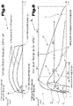
- An exemplary behavior of the turntable operating element 17 in the first operating mode B1 is shown in figure 5 schematically illustrated, while an exemplary behavior of the turntable control element 17 in the second operating mode B2 in 6 is shown schematically.
- figure 5 shows a possible course of movement over time during the normal or standard rotation of the actuating element 18.
- three possible courses of rotational movement of the actuating element 18 are shown in this diagram in correlation to the resulting machine movements.
- the rotary movements on the actuating element 18 are converted into proportional control commands or traversing movements of the controlled machine component.
- an adjustment or displacement movement of the controlled machine component takes place only as long as the actuating member 18 is also actuated or actively rotated by the operator.
- the adjustment movement of the controlled machine component also stops as simultaneously as possible or with a negligible delay, which can be caused, for example, by physical inertia or control-related computing times.
- a negligible delay can be caused, for example, by physical inertia or control-related computing times.
- the operator can easily control the movement speed and the respectively covered movement distance of the machine component.
- This operating mode B1 is particularly practical and/or particularly expedient for the sensitive movement of a controlled machine component if only relatively short travel distances have to be traveled until the set or desired position is reached.
- this first operating mode B1 which can also be referred to as proportional control mode
- different movement scalings or conversion ratios between the rotary movement of the actuating member 18 and the setting movement of the controlled machine component can also be provided.
- the ratio between the rotary movement of the actuating member 18 and the resulting machine movement is 1:1, while this ratio is 1:2 for the middle characteristic curve and 1:3 for the uppermost characteristic curve shown.
- These optionally implemented scalings or conversion ratios can be selected and preset by the operator or changed as required.
- a possible adjustment range can be in a range of values between 1:1 and 1:10 or more, with these ratios between the rotation on the actuating element 18 and the resulting movement of the machine component being heavily dependent on the respective application or machine can be dependent, in particular can be influenced by the actuating path to be covered in each case, the achievable actuating speed and/or the respective actuator.
- the actuating element 18 does not continue to run after the actuating element 18 has been released.
- the detent or braking torque of the turntable actuating element 17 or of its axis of rotation 22 can be correspondingly high. This can be done in a practical way via the rotary resistance generating means 23 - 4 - be hired, determined or co-determined.
- the detent or braking torque that is standard or that is caused by the mechanical design of the turntable operating element 17 in relation to the axis of rotation 22 is so high that with relatively slow, standard or sensitive rotary movements in relation to the actuating element 18 an overrun of the same does not occur or cannot occur.
- the operating member 18 is generally actively decelerated or actively brought to a standstill by the operator, as a result of which, due to the proportional control behavior in the first operating mode B1, the movement of the controlled machine component is also decelerated or stopped at the same time or almost at the same time standstill is brought to a standstill, as can be seen from the characteristic curves in figure 5 can be seen.
- the first operating mode B1 is essentially characterized and recognizable by the evaluation and control device 20 in that, at least initially, the operating member 18 is twisted or "turned up" relatively slowly by the operator or compared to the characteristic curves in 6 - Regarding the second operating mode B2 - a relatively low initial angular acceleration a ⁇ N occurs on the actuating member 18 or is present on its axis of rotation 22 .
- the evaluation and control device 20 can determine this, for example, based on the number of increments or sensor pulses per time unit, which are detected by the sensory detection means 21 - 4 - generated will.
- the angular velocity ⁇ of the actuating element 18 or its axis of rotation 22 at a predetermined, initial point in time can also be used as a criterion for activating operating mode B1 or B2 or as a criterion for switching between the two operating modes B1 and B2 - and vice versa - function.
- the angular velocity ⁇ of the actuating member 18 that is present in the initial phase of the initiation of a rotary movement is used as a criterion for the activation of the first or second operating mode B1, B2.
- the initial phase can be characterized by an evaluation time 24 - Figures 5, 6 - be defined or limited.
- the evaluation point in time 24 can, for example, be up to approximately 0.5 s after the start of the rotary movement of the actuating element 18 or its axis of rotation 22, or can be defined at another practicable point in time.
- switching to the second operating mode B2 can take place when a predefined threshold value of the rotary or angular velocity ⁇ of the actuating element 18 has reached or exceeded a predefined value at the evaluation time 24 or during a predefined evaluation phase.
- the corresponding angular velocity or angular acceleration threshold value can therefore be understood as a dynamic characteristic value of the rotational movement of the actuating element 18, as can also be seen from a synopsis of the Figures 5 and 6 can be seen.
- the system preferably automatically switches to the second operating mode B2 or then there is a criterion to activate the second operating mode B2 or to operate the turntable operating element 17 in the second operating mode B2.
- the initial phase of the initiation of a rotary movement on the actuating member 18 can be defined, for example, by a period of up to 1 second, preferably up to 0.5 seconds from the start of the rotary movement of the actuating member 18 .
- An expedient evaluation criterion for an automatic switching on or switching process in relation to the at least two operating modes B1, B2 is thus defined in that a comparison of at least one initial angular velocity or angular acceleration characteristic value of the actuating element 18 detected by sensors with at least one predefined threshold or limit value of the angular velocity or angular acceleration of the actuating member 18 is carried out.
- the evaluation and control device 20 can also be designed to initiate the second operating mode B2 or to switch to it if, in addition, a contact or grasping detection means 25 ( 4 ), for example by means of a capacitive sensor 26 ( 4 ), it is detected that the operating member 18 has been released by the operator.
- a contact or grasping detection means 25 or the capacitive sensor 26 can be assigned directly to the actuating element 18 and be line-connected to the electronic evaluation and control device 20 .
- the example start-up characteristic curve A1 in 6 is an initial angular acceleration a ⁇ 1 or an initial angular velocity ⁇ 1 of the actuating member 18, which causes the actuating member 18 to overrun during an overrun time TNL1.
- This run-on time TNL1 is mainly determined by the previously applied actuation pulse relative to the actuation element 18 and by the prevailing detent or braking torque relative to its axis of rotation 22 .
- the respective actuation pulse from the operator results in a corresponding angular velocity ⁇ 1 and angular acceleration a ⁇ 1 of the actuating element 18.
- a machine movement is only carried out according to the start-up characteristic curve A1 as long as the actuating element 18 continues to run due to the applied actuating impulse after the operator no longer touches the actuating element 18. Accordingly, when the rotational movement of the actuating member 18 is terminated, the machine movement is also terminated.
- the run-on behavior or the actual run-on time TNL1 of the actuating element 18 can optionally be generated by the evaluation and control device 20 by means of the rotary resistance generating means 23 4 - to be influenced.
- the run-on behavior or the actual run-on time TNL1 of the actuating element 18 is only determined by the mechanical properties of the rotary actuator operating element 17, in particular by the mass inertia of the actuating element 18 or by the friction values of its axis of rotation 22.
- the point in time at which the operating member 18 is released by the operator is illustrated by way of example with a circular symbol on the push-pull characteristic curve A1.
- the end time of the after-running of the actuating element 18 and the simultaneous stop of the movement of the controlled machine component is represented by a cross symbol on the time axis.
- An initial angular acceleration lies on the push-off characteristic A2 a ⁇ 2 or an initial angular velocity ⁇ 2 of the actuating member 18 which is higher than in the case of the push-pull characteristic curve A1. Accordingly, the actual run-on time TNL2 of the actuator can be at least slightly longer than the run-on time TNL1. In this case, however, the adjustment movement of the controlled machine component is continued without interruption during a virtual run-on time VNL2 in terms of control technology. This means that the machine movement is actively continued in accordance with the start-up characteristic curve 2 in terms of control technology is, although the actuator 18 has already come to a standstill at the exemplary time with the cross symbol.
- the controlled machine component continues to move according to a defined, for example gradually decaying, movement profile, while the actuating element 18 and its axis of rotation 22 have already come to a standstill.
- the behavior according to the push-pull characteristic curve A2 is determined by the evaluation and control device 20 due to a relatively high initial angular acceleration a ⁇ 2 or angular velocity ⁇ 2 of the actuating member 18 or initiated by its axis of rotation 22 or automatically implemented.
- An initial angular acceleration lies at the push-on characteristic curve A3 a ⁇ 3 or an initial angular velocity ⁇ 3 of the actuating member 18, which is higher in each case than in the case of the push-on characteristics A1 and A2.
- the actual run-on time TNL3 of the actuating element 18 can thus be at least slightly longer than the actual run-on time TNL2.
- the virtual run-on time VNL3 and/or the run-on speed can be set significantly longer or higher by the evaluation and control device 20 than is the case, for example, with the virtual run-on time VNL2 is available or applied.
- a ⁇ 3 or angular velocity ⁇ 3 of the actuating element 18 can be derived from the evaluation and control device 20 that the operator would like to achieve the longest possible run-on time, which can result from the actual run-on time TNL3 and the virtual run-on time VNL3 of the actuating element 18.
- the specified measures can be used to efficiently achieve dynamically scalable, control-technically determined or actively controlled follow-up behavior of machine movements, which can improve the operating ergonomics and also increase the cost-effectiveness of the control device 2, 2'.
- the durations TNL1, TNL2 and TNL3 in 6 can therefore also be zero or not exist at all. In particular, this can be due to the axis of rotation 22 or to the Actuator 18 acting detent or braking torque can be so high that the actuator 18 comes to a standstill immediately or without any significant delay after being released by the operator.
- the criteria described above, in particular the angular velocity or angular acceleration characteristic values presented above can be used in connection with the determination or initiation of the virtual run-on times VNL2, VNL3 of the controlled machine component.
- the relatively high braking or detent torque of the actuating element 18 or its axis of rotation 22 can be inherent or mechanically predefined, or generated or varied as needed by the controllable rotary resistance generating means 23 .
- the evaluation and control device 20 can also be designed in such a way that the second operating mode B2 ends and a currently executed adjustment movement of a controlled machine component is stopped immediately if a touch or grip detection means 25 ( 4 ), for example by means of a capacitive sensor 26 ( 4 ), it is detected that the operating member 18 was gripped again by the operator during the presence of the second operating mode B2 and the operator then did not initiate any rotary actuation, or the operator initiated a rotary actuation of the operating member 18 in the opposite direction.
- the second operating mode B2 can also be ended and a currently executed adjustment movement of a controlled machine component can be stopped immediately by the operator initiating a rotary actuation of the actuating element 18 in the opposite direction while the second operating mode B2 is present.
- the second operating mode B2 it is possible for the second operating mode B2 to end and a currently executed adjustment movement of a controlled machine component to be stopped immediately if the operator applies a minimum value of an axial force to the actuating element 18 in the axial direction of its axis of rotation 22, or in the axial direction of its axis of rotation 22 adjusted, in particular pushed in, is.
- An abort point 27 of a control-technically activated, trailing machine movement which can be initiated by an operator if required by the measures described above, in particular within the virtual run-on time VNL3 according to the start-up characteristic curve A3, is in 6 illustrated with a triangle symbol.
- the evaluation and control device 20 can also be designed to increase a follow-up time VNL2, VNL3 or a follow-up behavior, for example a speed profile, of the adjustment movement of the controlled machine component at least once or several times if the detected angular velocity ⁇ 2, ⁇ 3 or angular acceleration a ⁇ 2 , a ⁇ 3 of the actuating member 18 or its axis of rotation 22 reaches or exceeds at least one predefined threshold value twice or more within a predefined evaluation period t 1 .
- VNL2 follow-up time
- VNL3 or a follow-up behavior for example a speed profile
- the predefined evaluation period t 1 can be triggered by a renewed rotary actuation of the actuating element 18 before it comes to a standstill, or by a renewed rotary actuation of the actuating element 18 within less than 2 seconds, preferably less than 1 second, after the actuating element 18 has been released by the Operator to be defined.
- the human-machine interface 6 or the control device 2, 2 ', in particular the turntable operating element 17 or their evaluation and control device 20 can also be equipped with an acoustic and / or visual signaling device 28, 29 or line-connected.
- the acoustic and/or visual signaling device 28, 29 serves to signal to the operator, when the second operating mode B2 is present, that there is an active run-on phase or the respective run-on behavior of the controlled machine component. This is expedient in particular when virtual run-on times VNL2, VNL3 are present or activated by the control system, since in this case the actuating element 18 is stationary and nevertheless there is a typically decaying, trailing adjustment movement of the correspondingly controlled machine component.
- the acoustic and/or visual signaling device 28, 29 can be used to provide acoustic and/or visual feedback about the gradual elapse or expiry of the actual and/or virtual run-on time TNL1, TNL2, TNL3, VNL2, VNL3 and/or about the gradually decreasing Follow-up speed of the controlled machine component can be provided.
- the acoustic signaling device 28 can include at least one buzzer or loudspeaker 30 for this purpose.
- the visual signaling device 29 can include at least one display or display means 31 for this purpose, for example a remaining time display and/or a speed display in the form of numbers, bars or pointers.
- All information on value ranges in the present description is to be understood in such a way that it also includes any and all sub-ranges, e.g. the information 1 to 10 is to be understood in such a way that all sub-ranges, starting from the lower limit 1 and the upper limit 10, are also included , i.e. all subranges start with a lower limit of 1 or greater and end with an upper limit of 10 or less, e.g. 1 to 1.7, or 3.2 to 8.1, or 5.5 to 10.
- control system 30 speaker 2.2' control device 31 display means 3 machine 4 industrial robot angular acceleration 5 master computer normal turning 6 human-machine interface a ⁇ 1 , 2.3 angular acceleration 7 operator nudge 8th hand control ⁇ N angular velocity 9 control panel normal turning 10 input device ⁇ 1 , ⁇ 2 , ⁇ 3 angular velocity 11 touch-sensitive screen nudge 12 Enter key B1 first mode of operation 13 motion drive B2 second mode of operation 14 engine A1 Start-up characteristic 1 15 magnetic valve A2 Start-up characteristic 2 16 control element A3 Start-up characteristic 3 17 Turntable control TNL1 actual run-on time 1 18 actuator TNL2 actual follow-up time 2 19 mark TNL3 actual follow-up time 3 20 Evaluation and control device VNL2 virtual follow-up time 2 21 sensory detection means VNL3 virtual follow-
Landscapes
- Engineering & Computer Science (AREA)
- General Engineering & Computer Science (AREA)
- Physics & Mathematics (AREA)
- General Physics & Mathematics (AREA)
- Theoretical Computer Science (AREA)
- Human Computer Interaction (AREA)
- Automation & Control Theory (AREA)
- Manufacturing & Machinery (AREA)
- Numerical Control (AREA)
- Manipulator (AREA)
Claims (14)
- Dispositif de commande (2, 2') pour machines industrielles (3) avec des entraînements de déplacement contrôlés (13) pour des composants de la machine, comprenant une interface homme-machine (6) avec au moins un élément de commande (16) pour le contrôle manuel ou la spécification de déplacements de réglage d'au moins un des composants de la machine, dans lequel au moins un élément de commande (16) est conçu comme un élément de commande à actionneur rotatif (17) avec un organe d'actionnement (18) logé de manière rotative autour d'un axe de rotation (22), cet organe d'actionnement (18) pouvant être mis en rotation par la force d'actionnement d'un opérateur, dans lequel les mouvements rotatifs de l'organe d'actionnement (18) par rapport à son axe de rotation (22) sont évalués, afin d'en déduire des instructions, par un dispositif électronique d'analyse et de commande (20) et dans lequel le dispositif d'analyse et de commande (20) est conçu pour différencier automatiquement au moins entre un premier mode de fonctionnement (B1) et un deuxième mode de fonctionnement (B2), dans lequel, dans le premier mode de fonctionnement (B1), les mouvements de réglage d'un composant de machine contrôlé ne sont exécutés que tant que le dispositif d'analyse et de commande (20) détecte un mouvement de rotation de l'organe d'actionnement (18) par rapport à son axe de rotation (22), caractérisé en ce que, dans le deuxième mode de fonctionnement (B2), les mouvements de réglage d'un composant de machine contrôlé sont continués immédiatement après la fin du mouvement de rotation de l'organe d'actionnement (18) ou de son axe de rotation (22) sans interruption du mouvement de réglage du composant de machine contrôlé pendant un temps d'inertie limité (VNL2, VNL3), dans lequel la différenciation automatique entre les premier et deuxième modes de fonctionnement (B1, B2) est effectuée sur la base d'une vitesse angulaire (ωN, ω1, ω2, ω3) ou d'une accélération angulaire (


- Dispositif de commande selon la revendication 1, caractérisé en ce que le dispositif d'analyse et de commande (20) effectue une commutation dans le deuxième mode de fonctionnement (B2) ou une activation du deuxième mode de fonctionnement (B2) lorsque la vitesse angulaire (ω1, ω2, ω3) ou l'accélération angulaire (


- Dispositif de commande selon la revendication 1 ou 2, caractérisé en ce que le dispositif d'analyse et de commande (20) est conçu pour définir un temps d'inertie (VNL2, VNL3) ou un comportement inertiel du mouvement rotatif du composant de machine contrôlé en fonction de plusieurs valeurs seuils prédéfinies, ces différentes valeurs seuils étant définies par différentes vitesses angulaires ω2, ω3) ou accélérations angulaires (


- Dispositif de commande selon l'une des revendications précédentes, caractérisé en ce que le dispositif d'analyse et de commande (20) est conçu pour initier ou commuter dans le deuxième mode de fonctionnement (B2) lorsqu'il est détecté en outre, à l'aide d'un moyen de détection de contact ou de préhension (25), par exemple d'un capteur capacitif (26), que l'organe d'actionnement (18) a été relâché par l'opérateur.
- Dispositif de commande selon l'une des revendications précédentes, caractérisé en ce que le dispositif d'analyse et de commande (20) est conçu pour définir de manière différente un temps d'inertie (VNL2, VNL3) ou un comportement inertiel du mouvement rotatif du composant de machine contrôlé en fonction de la position actuelle du composant de machine contrôlé, par exemple par rapport à une position finale technique ou mécanique ou par rapport à un jeu de mouvement sans collision.
- Dispositif de commande selon l'une des revendications précédentes, caractérisé en ce que le dispositif d'analyse et de commande (20) est conçu pour augmenter au moins une fois ou plusieurs fois un temps d'inertie (VNL2, VNL3) ou un comportement inertiel, par exemple une évolution de la vitesse, du mouvement rotatif du composant de machine contrôlé lorsque la vitesse angulaire ω2, ω3) ou l'accélération angulaire (


- Dispositif de commande selon la revendication 6, caractérisé en ce que la période d'évaluation (t1) prédéfinie est définie par un nouvel actionnement rotatif de l'organe d'actionnement (18) avant son immobilisation ou par un nouvel actionnement rotatif de l'organe d'actionnement (18) dans un délai inférieur à 2 secondes, de préférence inférieur à 1 seconde, après le relâchement de l'organe d'actionnement (18) par l'opérateur.
- Dispositif de commande selon l'une des revendications précédentes, caractérisé en ce que le deuxième mode de fonctionnement (B2) se termine et un mouvement de réglage d'un composant de machine contrôlé, actuellement exécuté, est immédiatement stoppé lorsque, à l'aide d'un moyen de détection de contact ou de préhension (25), par exemple à l'aide d'un capteur capacitif (26), il est détecté que l'organe d'actionnement (18) est à nouveau saisi par l'opérateur pendant le deuxième mode de fonctionnement (B2) et qu'aucun actionnement rotatif n'est ensuite appliqué par l'opérateur ou que l'opérateur effectue un actionnement rotatif de l'organe d'actionnement (18) dans la direction opposée.
- Dispositif de commande selon l'une des revendications précédentes, caractérisé en ce que le deuxième mode de fonctionnement (B2) se termine et un mouvement de réglage d'un composant de machine contrôlé, actuellement exécuté, est immédiatement stoppé lorsque, pendant le deuxième mode de fonctionnement (B2), un actionnement rotatif de l'organe d'actionnement (18) est effectué par l'opérateur dans la direction opposée.
- Dispositif de commande selon l'une des revendications précédentes, caractérisé en ce que le deuxième mode de fonctionnement (B2) se termine et un mouvement de réglage d'un composant de machine contrôlé, actuellement exécuté, est immédiatement stoppé lorsque l'organe d'actionnement (18) est sollicité du côté de l'opérateur dans la direction axiale de son axe de rotation (22) avec une valeur minimale d'une force axiale ou est déplacé, plus particulièrement comprimé vers l'intérieur dans la direction axiale de son axe de rotation (22).
- Dispositif de commande selon l'une des revendications précédentes, caractérisé en ce qu'un dispositif de signalisation acoustique et/ou visuel (28, 29) est prévu, qui signale à l'opérateur, dans le deuxième mode de fonctionnement (B2), le comportement inertiel du composant de machine contrôlé, plus particulièrement pour l'émission d'un message de retour acoustique et/ou visuel grâce à l'écoulement ou à l'expiration progressive du temps d'inertie réel et/ou virtuel (TNL1, TNL2, TNL3, VNL2, VNL3) et/ou grâce à vitesse inertielle, diminuant progressivement, du composant de machine contrôlé.
- Dispositif de commande selon la revendication 11, caractérisé en ce que le dispositif de signalisation acoustique et/ou visuel (28, 29) comprend au moins un haut-parleur (30) et/ou au moins un moyen d'affichage (31), par exemple un affichage de temps restant et/ou un affichage de vitesse sous forme numérique, de barres ou d'aiguilles.
- Dispositif de commande selon l'une des revendications précédentes, caractérisé en ce que l'organe d'actionnement (18) ou son axe de rotation (22) est en interaction mécanique ou couplé en mouvement avec un moyen de production d'une résistance à la rotation (23) variable de manière contrôlée, dans lequel le dispositif d'analyse et de commande (20) est conçu pour le réglage variable des résistances à la rotation du moyen de production d'une résistance à la rotation (23).
- Procédé de fonctionnement d'un dispositif de commande (2, 2') pour des machines industrielles (3) avec des entraînements de déplacement contrôlés (13) pour des composants de la machine, dans lequel est prévue une interface homme-machine (6) avec au moins un élément de commande (16) pour le contrôle manuel ou la spécification de déplacements de réglage d'au moins un des composants de la machine, dans lequel au moins un élément de commande (16) est conçu comme un élément de commande à actionneur rotatif (17) avec un organe d'actionnement (18) logé de manière rotative autour d'un axe de rotation (22), cet organe d'actionnement (18) pouvant être mis en rotation par la force d'actionnement d'un opérateur, dans lequel les mouvements rotatifs de l'organe d'actionnement (18) par rapport à son axe de rotation (22) sont évalués, afin d'en déduire des instructions, par un dispositif électronique d'analyse et de commande (20) et dans lequel le dispositif d'analyse et de commande (20) est conçu pour différencier automatiquement au moins entre un premier mode de fonctionnement (B1) et un deuxième mode de fonctionnement (B2), dans lequel, dans le premier mode de fonctionnement (B 1), les mouvements de réglage d'un composant de machine contrôlé ne sont exécutés que tant que le dispositif d'analyse et de commande (20) détecte un mouvement de rotation de l'organe d'actionnement (18) par rapport à son axe de rotation (22), caractérisé en ce que, dans le deuxième mode de fonctionnement (B2), les mouvements de réglage d'un composant de machine contrôlé sont continués immédiatement après la fin du mouvement de rotation de l'organe d'actionnement (18) ou de son axe de rotation (22) sans interruption du mouvement de réglage du composant de machine contrôlé pendant un temps d'inertie limité (VNL2, VNL3), dans lequel la différenciation automatique entre les premier et deuxième modes de fonctionnement (B 1, B2) est effectuée sur la base d'une vitesse angulaire (ωN, ω1, ω2, ω3) ou d'une accélération angulaire (


Applications Claiming Priority (2)
| Application Number | Priority Date | Filing Date | Title |
|---|---|---|---|
| ATA50642/2017A AT520247B1 (de) | 2017-08-01 | 2017-08-01 | Steuervorrichtung für industrielle Maschinen |
| PCT/AT2018/060168 WO2019023728A2 (fr) | 2017-08-01 | 2018-07-27 | Dispositif de commande pour machines industrielles |
Publications (2)
| Publication Number | Publication Date |
|---|---|
| EP3662346A2 EP3662346A2 (fr) | 2020-06-10 |
| EP3662346B1 true EP3662346B1 (fr) | 2022-06-22 |
Family
ID=63517621
Family Applications (1)
| Application Number | Title | Priority Date | Filing Date |
|---|---|---|---|
| EP18765536.0A Active EP3662346B1 (fr) | 2017-08-01 | 2018-07-27 | Dispositif de commande pour machines industrielles |
Country Status (4)
| Country | Link |
|---|---|
| EP (1) | EP3662346B1 (fr) |
| JP (1) | JP7216708B2 (fr) |
| AT (1) | AT520247B1 (fr) |
| WO (1) | WO2019023728A2 (fr) |
Families Citing this family (1)
| Publication number | Priority date | Publication date | Assignee | Title |
|---|---|---|---|---|
| DE102022115764A1 (de) * | 2022-06-24 | 2024-01-04 | Signata GmbH | Verfahren zum Erkennen einer Griffart eines ein rotatorisches Bedienelement benutzenden Bedieners |
Family Cites Families (14)
| Publication number | Priority date | Publication date | Assignee | Title |
|---|---|---|---|---|
| JP2000137513A (ja) * | 1998-10-30 | 2000-05-16 | Tsudakoma Corp | Nc円テーブル用制御装置 |
| DE10029191A1 (de) * | 2000-06-19 | 2001-12-20 | Philips Corp Intellectual Pty | Elektronisch gesteuerter Flüssigkeitsdrehknopf als haptisches Bedienelement |
| US7208939B2 (en) * | 2001-02-28 | 2007-04-24 | Bvr Technologies Co. | Methods and apparatus for sensing angular position and speed of a rotatable shaft utilizing linearized annular magnet and commutated ratiometric hall sensors |
| DE10245354A1 (de) * | 2002-09-27 | 2004-04-08 | Philips Intellectual Property & Standards Gmbh | Fernsteuerung |
| DE10245333A1 (de) * | 2002-09-27 | 2004-04-08 | Robert Bosch Gmbh | Eingabevorrichtung |
| US7570254B2 (en) * | 2004-11-09 | 2009-08-04 | Takahiko Suzuki | Haptic feedback controller, method of controlling the same, and method of transmitting messages that uses a haptic feedback controller |
| JP2009296305A (ja) * | 2008-06-05 | 2009-12-17 | Sony Corp | 操作装置、映像再生装置、操作情報出力方法 |
| DE102009037184A1 (de) * | 2009-08-12 | 2011-02-17 | Bayerische Motoren Werke Aktiengesellschaft | Bedienelement für ein Stellorgan mit viertueller Masse |
| DE102015110634A1 (de) * | 2015-07-01 | 2017-01-05 | Inventus Engineering Gmbh | Minicomputer und Verfahren |
| FR3010548B1 (fr) * | 2013-09-09 | 2016-12-23 | Dav | Interface de commande a retour haptique |
| JP6866566B2 (ja) * | 2015-03-19 | 2021-04-28 | 株式会社デンソーウェーブ | ロボット操作装置、及びロボット操作プログラム |
| US9857962B2 (en) * | 2015-03-19 | 2018-01-02 | Denso Wave Incorporated | Robot operation apparatus and robot operation program product |
| CN104908046B (zh) * | 2015-06-16 | 2017-01-11 | 东南大学 | 一种基于旋钮式力反馈手控器及机械臂遥操作控制方法 |
| AT519166A2 (de) * | 2016-09-14 | 2018-04-15 | Keba Ag | Steuervorrichtung zum Betreiben einer Werkzeugmaschine, insbesondere einer Fräs- oder Drehmaschine, sowie entsprechende Werkzeugmaschine |
-
2017
- 2017-08-01 AT ATA50642/2017A patent/AT520247B1/de not_active IP Right Cessation
-
2018
- 2018-07-27 JP JP2020505339A patent/JP7216708B2/ja active Active
- 2018-07-27 EP EP18765536.0A patent/EP3662346B1/fr active Active
- 2018-07-27 WO PCT/AT2018/060168 patent/WO2019023728A2/fr not_active Ceased
Also Published As
| Publication number | Publication date |
|---|---|
| JP7216708B2 (ja) | 2023-02-01 |
| WO2019023728A3 (fr) | 2019-03-28 |
| JP2021501925A (ja) | 2021-01-21 |
| WO2019023728A2 (fr) | 2019-02-07 |
| AT520247A1 (de) | 2019-02-15 |
| AT520247B1 (de) | 2019-04-15 |
| EP3662346A2 (fr) | 2020-06-10 |
Similar Documents
| Publication | Publication Date | Title |
|---|---|---|
| EP3512669B1 (fr) | Dispositif de commande et procédé de commande pour machines industrielles à entraînement de déplacement commandé | |
| EP2709803B2 (fr) | Procédé pour agir par commande manuelle sur les mouvements d'une machine ou d'une installation, et unité de commande de machine correspondante | |
| EP3645919B1 (fr) | Dispositif et procédé de sélection de rapports dans des véhicules à moteur | |
| EP1075979B1 (fr) | Procédé pour la mise en oeuvre d'un dispositif de commande multifonctions d'automobile et dispositif de commande multifonctions | |
| EP3393843B1 (fr) | Véhicule muni d'une unité d'acquisition d'images et d'un système d'actionnement servant à actionner les dispositifs du véhicule et procédé servant à faire fonctionner le système d'actionnement | |
| EP3347226B1 (fr) | Système de commande pour véhicule automobile, muni d'une commande à écran tactile | |
| EP3688549A1 (fr) | Équipement commutateur | |
| EP3513261B1 (fr) | Dispositif de commande permettant de faire fonctionner une machine-outil, en particulier une fraiseuse ou un tour, et machine-outil correspondante | |
| EP2822799B1 (fr) | Actionneur rotatif | |
| EP3343311B1 (fr) | Levier de commande pourvu d'unité de rétroaction active | |
| EP3477419B1 (fr) | Unité de commande destinée à la commande des machines ou analogues | |
| EP3662345B1 (fr) | Dispositif de commande de machines industrielles | |
| EP4137898B1 (fr) | Dispositif de commande pour une commande cnc | |
| AT520247B1 (de) | Steuervorrichtung für industrielle Maschinen | |
| EP3513259B1 (fr) | Dispositif de commande et procédé de commande de machines industrielles comportant des mécanismes de déplacement commandés | |
| DE102012018713A1 (de) | Maschinensteuerung und Verfahren zum Steuern einer Maschine | |
| WO2017032688A1 (fr) | Dispositif et procédé de génération d'un couple haptique sur un actionneur | |
| WO2005029983A1 (fr) | Unite de commande pour une machine de l'industrie de traitement du tabac | |
| EP3513260B1 (fr) | Dispositif de commande et procédé de commande de machines industrielles comportant des mécanismes de déplacement commandés | |
| DE102019114973A1 (de) | Sicherheitsschaltelement für Maschinen oder Roboter | |
| EP3561185A1 (fr) | Appareil à commande manuelle pourvu de commutateur de fonctions |
Legal Events
| Date | Code | Title | Description |
|---|---|---|---|
| STAA | Information on the status of an ep patent application or granted ep patent |
Free format text: STATUS: UNKNOWN |
|
| STAA | Information on the status of an ep patent application or granted ep patent |
Free format text: STATUS: THE INTERNATIONAL PUBLICATION HAS BEEN MADE |
|
| PUAI | Public reference made under article 153(3) epc to a published international application that has entered the european phase |
Free format text: ORIGINAL CODE: 0009012 |
|
| STAA | Information on the status of an ep patent application or granted ep patent |
Free format text: STATUS: REQUEST FOR EXAMINATION WAS MADE |
|
| 17P | Request for examination filed |
Effective date: 20200228 |
|
| AK | Designated contracting states |
Kind code of ref document: A2 Designated state(s): AL AT BE BG CH CY CZ DE DK EE ES FI FR GB GR HR HU IE IS IT LI LT LU LV MC MK MT NL NO PL PT RO RS SE SI SK SM TR |
|
| AX | Request for extension of the european patent |
Extension state: BA ME |
|
| DAV | Request for validation of the european patent (deleted) | ||
| DAX | Request for extension of the european patent (deleted) | ||
| REG | Reference to a national code |
Ref country code: DE Ref legal event code: R079 Ref document number: 502018009996 Country of ref document: DE Free format text: PREVIOUS MAIN CLASS: G05G0005030000 Ipc: G05B0019042000 |
|
| RIC1 | Information provided on ipc code assigned before grant |
Ipc: G05G 1/08 20060101ALI20211112BHEP Ipc: G06F 3/01 20060101ALI20211112BHEP Ipc: G06F 3/038 20130101ALI20211112BHEP Ipc: G06F 3/0362 20130101ALI20211112BHEP Ipc: G05B 19/042 20060101AFI20211112BHEP |
|
| GRAP | Despatch of communication of intention to grant a patent |
Free format text: ORIGINAL CODE: EPIDOSNIGR1 |
|
| STAA | Information on the status of an ep patent application or granted ep patent |
Free format text: STATUS: GRANT OF PATENT IS INTENDED |
|
| INTG | Intention to grant announced |
Effective date: 20220107 |
|
| GRAS | Grant fee paid |
Free format text: ORIGINAL CODE: EPIDOSNIGR3 |
|
| GRAA | (expected) grant |
Free format text: ORIGINAL CODE: 0009210 |
|
| STAA | Information on the status of an ep patent application or granted ep patent |
Free format text: STATUS: THE PATENT HAS BEEN GRANTED |
|
| RAP1 | Party data changed (applicant data changed or rights of an application transferred) |
Owner name: KEBA INDUSTRIAL AUTOMATION GMBH |
|
| AK | Designated contracting states |
Kind code of ref document: B1 Designated state(s): AL AT BE BG CH CY CZ DE DK EE ES FI FR GB GR HR HU IE IS IT LI LT LU LV MC MK MT NL NO PL PT RO RS SE SI SK SM TR |
|
| REG | Reference to a national code |
Ref country code: GB Ref legal event code: FG4D Free format text: NOT ENGLISH |
|
| REG | Reference to a national code |
Ref country code: CH Ref legal event code: EP |
|
| REG | Reference to a national code |
Ref country code: DE Ref legal event code: R096 Ref document number: 502018009996 Country of ref document: DE |
|
| REG | Reference to a national code |
Ref country code: AT Ref legal event code: REF Ref document number: 1500167 Country of ref document: AT Kind code of ref document: T Effective date: 20220715 |
|
| REG | Reference to a national code |
Ref country code: IE Ref legal event code: FG4D Free format text: LANGUAGE OF EP DOCUMENT: GERMAN |
|
| REG | Reference to a national code |
Ref country code: LT Ref legal event code: MG9D |
|
| REG | Reference to a national code |
Ref country code: NL Ref legal event code: MP Effective date: 20220622 |
|
| PG25 | Lapsed in a contracting state [announced via postgrant information from national office to epo] |
Ref country code: SE Free format text: LAPSE BECAUSE OF FAILURE TO SUBMIT A TRANSLATION OF THE DESCRIPTION OR TO PAY THE FEE WITHIN THE PRESCRIBED TIME-LIMIT Effective date: 20220622 Ref country code: NO Free format text: LAPSE BECAUSE OF FAILURE TO SUBMIT A TRANSLATION OF THE DESCRIPTION OR TO PAY THE FEE WITHIN THE PRESCRIBED TIME-LIMIT Effective date: 20220922 Ref country code: LT Free format text: LAPSE BECAUSE OF FAILURE TO SUBMIT A TRANSLATION OF THE DESCRIPTION OR TO PAY THE FEE WITHIN THE PRESCRIBED TIME-LIMIT Effective date: 20220622 Ref country code: HR Free format text: LAPSE BECAUSE OF FAILURE TO SUBMIT A TRANSLATION OF THE DESCRIPTION OR TO PAY THE FEE WITHIN THE PRESCRIBED TIME-LIMIT Effective date: 20220622 Ref country code: GR Free format text: LAPSE BECAUSE OF FAILURE TO SUBMIT A TRANSLATION OF THE DESCRIPTION OR TO PAY THE FEE WITHIN THE PRESCRIBED TIME-LIMIT Effective date: 20220923 Ref country code: FI Free format text: LAPSE BECAUSE OF FAILURE TO SUBMIT A TRANSLATION OF THE DESCRIPTION OR TO PAY THE FEE WITHIN THE PRESCRIBED TIME-LIMIT Effective date: 20220622 Ref country code: BG Free format text: LAPSE BECAUSE OF FAILURE TO SUBMIT A TRANSLATION OF THE DESCRIPTION OR TO PAY THE FEE WITHIN THE PRESCRIBED TIME-LIMIT Effective date: 20220922 |
|
| PG25 | Lapsed in a contracting state [announced via postgrant information from national office to epo] |
Ref country code: RS Free format text: LAPSE BECAUSE OF FAILURE TO SUBMIT A TRANSLATION OF THE DESCRIPTION OR TO PAY THE FEE WITHIN THE PRESCRIBED TIME-LIMIT Effective date: 20220622 Ref country code: LV Free format text: LAPSE BECAUSE OF FAILURE TO SUBMIT A TRANSLATION OF THE DESCRIPTION OR TO PAY THE FEE WITHIN THE PRESCRIBED TIME-LIMIT Effective date: 20220622 |
|
| PG25 | Lapsed in a contracting state [announced via postgrant information from national office to epo] |
Ref country code: NL Free format text: LAPSE BECAUSE OF FAILURE TO SUBMIT A TRANSLATION OF THE DESCRIPTION OR TO PAY THE FEE WITHIN THE PRESCRIBED TIME-LIMIT Effective date: 20220622 |
|
| PG25 | Lapsed in a contracting state [announced via postgrant information from national office to epo] |
Ref country code: SM Free format text: LAPSE BECAUSE OF FAILURE TO SUBMIT A TRANSLATION OF THE DESCRIPTION OR TO PAY THE FEE WITHIN THE PRESCRIBED TIME-LIMIT Effective date: 20220622 Ref country code: SK Free format text: LAPSE BECAUSE OF FAILURE TO SUBMIT A TRANSLATION OF THE DESCRIPTION OR TO PAY THE FEE WITHIN THE PRESCRIBED TIME-LIMIT Effective date: 20220622 Ref country code: RO Free format text: LAPSE BECAUSE OF FAILURE TO SUBMIT A TRANSLATION OF THE DESCRIPTION OR TO PAY THE FEE WITHIN THE PRESCRIBED TIME-LIMIT Effective date: 20220622 Ref country code: PT Free format text: LAPSE BECAUSE OF FAILURE TO SUBMIT A TRANSLATION OF THE DESCRIPTION OR TO PAY THE FEE WITHIN THE PRESCRIBED TIME-LIMIT Effective date: 20221024 Ref country code: ES Free format text: LAPSE BECAUSE OF FAILURE TO SUBMIT A TRANSLATION OF THE DESCRIPTION OR TO PAY THE FEE WITHIN THE PRESCRIBED TIME-LIMIT Effective date: 20220622 Ref country code: EE Free format text: LAPSE BECAUSE OF FAILURE TO SUBMIT A TRANSLATION OF THE DESCRIPTION OR TO PAY THE FEE WITHIN THE PRESCRIBED TIME-LIMIT Effective date: 20220622 Ref country code: CZ Free format text: LAPSE BECAUSE OF FAILURE TO SUBMIT A TRANSLATION OF THE DESCRIPTION OR TO PAY THE FEE WITHIN THE PRESCRIBED TIME-LIMIT Effective date: 20220622 |
|
| PG25 | Lapsed in a contracting state [announced via postgrant information from national office to epo] |
Ref country code: PL Free format text: LAPSE BECAUSE OF FAILURE TO SUBMIT A TRANSLATION OF THE DESCRIPTION OR TO PAY THE FEE WITHIN THE PRESCRIBED TIME-LIMIT Effective date: 20220622 Ref country code: IS Free format text: LAPSE BECAUSE OF FAILURE TO SUBMIT A TRANSLATION OF THE DESCRIPTION OR TO PAY THE FEE WITHIN THE PRESCRIBED TIME-LIMIT Effective date: 20221022 |
|
| REG | Reference to a national code |
Ref country code: DE Ref legal event code: R097 Ref document number: 502018009996 Country of ref document: DE |
|
| REG | Reference to a national code |
Ref country code: BE Ref legal event code: MM Effective date: 20220731 |
|
| PG25 | Lapsed in a contracting state [announced via postgrant information from national office to epo] |
Ref country code: MC Free format text: LAPSE BECAUSE OF FAILURE TO SUBMIT A TRANSLATION OF THE DESCRIPTION OR TO PAY THE FEE WITHIN THE PRESCRIBED TIME-LIMIT Effective date: 20220622 Ref country code: AL Free format text: LAPSE BECAUSE OF FAILURE TO SUBMIT A TRANSLATION OF THE DESCRIPTION OR TO PAY THE FEE WITHIN THE PRESCRIBED TIME-LIMIT Effective date: 20220622 |
|
| PG25 | Lapsed in a contracting state [announced via postgrant information from national office to epo] |
Ref country code: LU Free format text: LAPSE BECAUSE OF NON-PAYMENT OF DUE FEES Effective date: 20220727 Ref country code: DK Free format text: LAPSE BECAUSE OF FAILURE TO SUBMIT A TRANSLATION OF THE DESCRIPTION OR TO PAY THE FEE WITHIN THE PRESCRIBED TIME-LIMIT Effective date: 20220622 |
|
| PLBE | No opposition filed within time limit |
Free format text: ORIGINAL CODE: 0009261 |
|
| STAA | Information on the status of an ep patent application or granted ep patent |
Free format text: STATUS: NO OPPOSITION FILED WITHIN TIME LIMIT |
|
| GBPC | Gb: european patent ceased through non-payment of renewal fee |
Effective date: 20220922 |
|
| 26N | No opposition filed |
Effective date: 20230323 |
|
| PG25 | Lapsed in a contracting state [announced via postgrant information from national office to epo] |
Ref country code: BE Free format text: LAPSE BECAUSE OF NON-PAYMENT OF DUE FEES Effective date: 20220731 |
|
| PG25 | Lapsed in a contracting state [announced via postgrant information from national office to epo] |
Ref country code: IE Free format text: LAPSE BECAUSE OF NON-PAYMENT OF DUE FEES Effective date: 20220727 Ref country code: FR Free format text: LAPSE BECAUSE OF NON-PAYMENT OF DUE FEES Effective date: 20220822 |
|
| PG25 | Lapsed in a contracting state [announced via postgrant information from national office to epo] |
Ref country code: SI Free format text: LAPSE BECAUSE OF FAILURE TO SUBMIT A TRANSLATION OF THE DESCRIPTION OR TO PAY THE FEE WITHIN THE PRESCRIBED TIME-LIMIT Effective date: 20220622 |
|
| PG25 | Lapsed in a contracting state [announced via postgrant information from national office to epo] |
Ref country code: GB Free format text: LAPSE BECAUSE OF NON-PAYMENT OF DUE FEES Effective date: 20220922 |
|
| PGFP | Annual fee paid to national office [announced via postgrant information from national office to epo] |
Ref country code: AT Payment date: 20230616 Year of fee payment: 6 |
|
| PG25 | Lapsed in a contracting state [announced via postgrant information from national office to epo] |
Ref country code: MK Free format text: LAPSE BECAUSE OF FAILURE TO SUBMIT A TRANSLATION OF THE DESCRIPTION OR TO PAY THE FEE WITHIN THE PRESCRIBED TIME-LIMIT Effective date: 20220622 Ref country code: CY Free format text: LAPSE BECAUSE OF FAILURE TO SUBMIT A TRANSLATION OF THE DESCRIPTION OR TO PAY THE FEE WITHIN THE PRESCRIBED TIME-LIMIT Effective date: 20220622 |
|
| PG25 | Lapsed in a contracting state [announced via postgrant information from national office to epo] |
Ref country code: HU Free format text: LAPSE BECAUSE OF FAILURE TO SUBMIT A TRANSLATION OF THE DESCRIPTION OR TO PAY THE FEE WITHIN THE PRESCRIBED TIME-LIMIT; INVALID AB INITIO Effective date: 20180727 |
|
| PG25 | Lapsed in a contracting state [announced via postgrant information from national office to epo] |
Ref country code: MT Free format text: LAPSE BECAUSE OF FAILURE TO SUBMIT A TRANSLATION OF THE DESCRIPTION OR TO PAY THE FEE WITHIN THE PRESCRIBED TIME-LIMIT Effective date: 20220622 |
|
| PG25 | Lapsed in a contracting state [announced via postgrant information from national office to epo] |
Ref country code: BG Free format text: LAPSE BECAUSE OF FAILURE TO SUBMIT A TRANSLATION OF THE DESCRIPTION OR TO PAY THE FEE WITHIN THE PRESCRIBED TIME-LIMIT Effective date: 20220622 |
|
| PG25 | Lapsed in a contracting state [announced via postgrant information from national office to epo] |
Ref country code: BG Free format text: LAPSE BECAUSE OF FAILURE TO SUBMIT A TRANSLATION OF THE DESCRIPTION OR TO PAY THE FEE WITHIN THE PRESCRIBED TIME-LIMIT Effective date: 20220622 |
|
| REG | Reference to a national code |
Ref country code: AT Ref legal event code: MM01 Ref document number: 1500167 Country of ref document: AT Kind code of ref document: T Effective date: 20240727 |
|
| PG25 | Lapsed in a contracting state [announced via postgrant information from national office to epo] |
Ref country code: AT Free format text: LAPSE BECAUSE OF NON-PAYMENT OF DUE FEES Effective date: 20240727 |
|
| PGFP | Annual fee paid to national office [announced via postgrant information from national office to epo] |
Ref country code: DE Payment date: 20250724 Year of fee payment: 8 |
|
| PGFP | Annual fee paid to national office [announced via postgrant information from national office to epo] |
Ref country code: IT Payment date: 20250715 Year of fee payment: 8 |
|
| PGFP | Annual fee paid to national office [announced via postgrant information from national office to epo] |
Ref country code: CH Payment date: 20250807 Year of fee payment: 8 |
|
| PG25 | Lapsed in a contracting state [announced via postgrant information from national office to epo] |
Ref country code: TR Free format text: LAPSE BECAUSE OF FAILURE TO SUBMIT A TRANSLATION OF THE DESCRIPTION OR TO PAY THE FEE WITHIN THE PRESCRIBED TIME-LIMIT Effective date: 20220622 |