EP4137898B1 - Dispositif de commande pour une commande cnc - Google Patents
Dispositif de commande pour une commande cnc Download PDFInfo
- Publication number
- EP4137898B1 EP4137898B1 EP21192416.2A EP21192416A EP4137898B1 EP 4137898 B1 EP4137898 B1 EP 4137898B1 EP 21192416 A EP21192416 A EP 21192416A EP 4137898 B1 EP4137898 B1 EP 4137898B1
- Authority
- EP
- European Patent Office
- Prior art keywords
- operating
- tool
- ovr
- spindle
- rotary
- Prior art date
- Legal status (The legal status is an assumption and is not a legal conclusion. Google has not performed a legal analysis and makes no representation as to the accuracy of the status listed.)
- Active
Links
Images


Classifications
-
- B—PERFORMING OPERATIONS; TRANSPORTING
- B23—MACHINE TOOLS; METAL-WORKING NOT OTHERWISE PROVIDED FOR
- B23Q—DETAILS, COMPONENTS, OR ACCESSORIES FOR MACHINE TOOLS, e.g. ARRANGEMENTS FOR COPYING OR CONTROLLING; MACHINE TOOLS IN GENERAL CHARACTERISED BY THE CONSTRUCTION OF PARTICULAR DETAILS OR COMPONENTS; COMBINATIONS OR ASSOCIATIONS OF METAL-WORKING MACHINES, NOT DIRECTED TO A PARTICULAR RESULT
- B23Q15/00—Automatic control or regulation of feed movement, cutting velocity or position of tool or work
- B23Q15/007—Automatic control or regulation of feed movement, cutting velocity or position of tool or work while the tool acts upon the workpiece
- B23Q15/12—Adaptive control, i.e. adjusting itself to have a performance which is optimum according to a preassigned criterion
-
- G—PHYSICS
- G05—CONTROLLING; REGULATING
- G05B—CONTROL OR REGULATING SYSTEMS IN GENERAL; FUNCTIONAL ELEMENTS OF SUCH SYSTEMS; MONITORING OR TESTING ARRANGEMENTS FOR SUCH SYSTEMS OR ELEMENTS
- G05B19/00—Program-control systems
- G05B19/02—Program-control systems electric
- G05B19/18—Numerical control [NC], i.e. automatically operating machines, in particular machine tools, e.g. in a manufacturing environment, so as to execute positioning, movement or co-ordinated operations by means of program data in numerical form
- G05B19/409—Numerical control [NC], i.e. automatically operating machines, in particular machine tools, e.g. in a manufacturing environment, so as to execute positioning, movement or co-ordinated operations by means of program data in numerical form characterised by using manual data input [MDI] or by using control panel, e.g. controlling functions with the panel; characterised by control panel details or by setting parameters
-
- G—PHYSICS
- G05—CONTROLLING; REGULATING
- G05B—CONTROL OR REGULATING SYSTEMS IN GENERAL; FUNCTIONAL ELEMENTS OF SUCH SYSTEMS; MONITORING OR TESTING ARRANGEMENTS FOR SUCH SYSTEMS OR ELEMENTS
- G05B2219/00—Program-control systems
- G05B2219/30—Nc systems
- G05B2219/35—Nc in input of data, input till input file format
- G05B2219/35442—Hand wheel turns resolver to control movement slide
-
- G—PHYSICS
- G05—CONTROLLING; REGULATING
- G05B—CONTROL OR REGULATING SYSTEMS IN GENERAL; FUNCTIONAL ELEMENTS OF SUCH SYSTEMS; MONITORING OR TESTING ARRANGEMENTS FOR SUCH SYSTEMS OR ELEMENTS
- G05B2219/00—Program-control systems
- G05B2219/30—Nc systems
- G05B2219/35—Nc in input of data, input till input file format
- G05B2219/35465—Hand wheel
-
- Y—GENERAL TAGGING OF NEW TECHNOLOGICAL DEVELOPMENTS; GENERAL TAGGING OF CROSS-SECTIONAL TECHNOLOGIES SPANNING OVER SEVERAL SECTIONS OF THE IPC; TECHNICAL SUBJECTS COVERED BY FORMER USPC CROSS-REFERENCE ART COLLECTIONS [XRACs] AND DIGESTS
- Y02—TECHNOLOGIES OR APPLICATIONS FOR MITIGATION OR ADAPTATION AGAINST CLIMATE CHANGE
- Y02P—CLIMATE CHANGE MITIGATION TECHNOLOGIES IN THE PRODUCTION OR PROCESSING OF GOODS
- Y02P90/00—Enabling technologies with a potential contribution to greenhouse gas [GHG] emissions mitigation
- Y02P90/02—Total factory control, e.g. smart factories, flexible manufacturing systems [FMS] or integrated manufacturing systems [IMS]
Definitions
- the invention relates to an operating device for a CNC control for controlling a machine tool, wherein the machine tool comprises several machine axes by means of which a tool inserted into a tool holder of a tool spindle can be adjusted relative to a workpiece and/or rotated about a tool spindle axis.
- the invention relates to a method for operating a machine tool controlled by means of a CNC control comprising such an operating device.
- control device such as a CNC control.
- the control device uses a parts program to "control” the movements of machine elements and thus the movements of a tool, which is, for example, introduced into the machine via a tool holder, relative to a workpiece, which is also introduced into the machine.
- control is in common usage and not “control” in the sense of control engineering.
- Control here primarily means the specification of position setpoints for the position control of axes, behind which control processes in the sense of control engineering are hidden.
- the part program consists at least predominantly of control commands that are read in and interpreted by the control device.
- the control device controls the movements of the machine elements of the machine tool and thus the movement of the tool relative to the workpiece.
- the part program can be created manually using an editor directly on the machine or on an external computer.
- movement information about the movements of the tool to be carried out is usually generated by a CAM system (Computer Aided Manufacturing), preferably in a standardized data format, and read in by a downstream postprocessor.
- a CAM system Computer Aided Manufacturing
- the postprocessor uses the movement information generated by the CAM system, the kinematics and machine data of the machine tool, the command set of the CNC control and the command set of the PLC control, the postprocessor generates a parts program adapted to the specific machine tool on which the machining process is to take place, in the form of control commands adapted to the specific control device of the machine tool.
- the postprocessor converts the movement information generated by the CAM system, preferably in a standardized data format, into control commands that can be read in by the control device and are adapted to the specific control device.
- the postprocessor takes into account the specific machine-specific kinematic conditions of the machine tool, such as kinematics, geometric proportions, maximum travel ranges of the drive axes and maximum speeds of the machine elements. This data is available in the form of machine data. Furthermore, when generating the control commands, the postprocessor takes into account machine-specific PLC (Programmable Logic Control) functionalities, such as lubrication, tool change, door locking, etc., whereby the specific PLC functionalities available are available to the postprocessor in the form of PLC command sets.
- PLC Programmable Logic Control
- Machine tools are operated via operating devices such as an HMI (Human Machine Interface) of the CNC control, a machine control panel that can be connected to the CNC control (MCP or Machine Control Panel) or by means of handheld control devices.
- Control devices for machine tools have at least one, but often several, override (OVR) control elements (hereinafter also referred to as “override”) to influence the control variables feed rate (in short: feed) of the feed axes or spindle speed of the main spindle.
- OVR override
- Known operating devices for CNC controls have a single feed override with which both the working feed (the feed rate for the application in which the tool is in engagement with the workpiece) and the rapid traverse (the feed or rapid traverse rate for the application in which the tool is not in engagement with the workpiece) can be set separately, depending on which application is currently present when the feed override is activated.
- operating devices are also known that use separate feed overrides for the working feed and the rapid traverse.
- control variable is not set absolutely using the control element (e.g. the spindle speed directly in rpm), but is changed as a percentage of a programmed value, e.g. in a value range from 0% to 120% of the programmed value.
- override actuators are designed as rotary actuators with fixed stops that can be set in a specific angle range, e.g. between 0° and 270°, by manually operating a rotary knob.
- override actuators in the form of endlessly rotating rotary actuators are also known.
- rotary actuators are understood to mean not only “pure” rotary actuators that only allow the manual operation of a rotary knob, but also those operating elements that, in addition to the rotary knob, also include at least one push button switch (also referred to as a rotary push button) or the function of a control lever (joystick), etc.
- control variable often does not change linearly with the override setting (i.e. the angle of rotation of the rotary knob), but in discrete steps.
- override setting i.e. the angle of rotation of the rotary knob
- 16 different angle ranges of a rotary actuator can each be assigned to a spindle speed. This is done, for example, for settings between 50% and 120%, evenly divided into 5% steps.
- angle of rotation can be understood as both the absolute angle that the rotary actuator currently assumes (e.g. 0° or 180°), but also the angle range that is covered by a certain operating action (e.g. 20° when changing from 180° to 200°). The respective meaning arises from the context.
- the feed rate for machine tools is the speed at which the tool moves "through the workpiece" relative to the workpiece to machine the workpiece, i.e. the speed at which the tool is “engaged”.
- the feed override is usually used to influence movements of the machine axes in which the tool is not engaged, e.g. so-called rapid traverse movements.
- the terms feed override and feed rate expressly include movements in which the tool is not engaged, such as rapid traverse movements.
- Documents WO 2018/049450 A2 , EP 3 130 973 A1 and WO 2019/023727 A2 also represent the state of the art.
- a disadvantage of today's rotary actuators for influencing the feed rate or spindle speed of machine tools is their lack of flexibility with regard to adaptation to the needs of the individual user.
- One object of the present invention is therefore to improve the flexibility with regard to adaptation to the needs of the individual user in rotary actuators for influencing the feed rate or spindle speed of machine tools.
- an operating device for a CNC control for controlling a machine tool with the features specified in claim 1, i.e. an operating device for a CNC control for controlling a machine tool, wherein the machine tool comprises a plurality of machine axes by means of which a tool inserted into a tool holder of a tool spindle can be adjusted relative to a workpiece and/or rotated about a tool spindle axis, wherein the operating device has at least one endlessly rotatable rotary actuator that can be operated manually by an operator of the operating device, by means of which a feed rate at which the tool moves relative to the workpiece and/or a spindle speed can be manually adjusted by the operator by turning a rotary knob of the rotary actuator, wherein the operating device comprises a graphical user interface by means of which the effect of an operating action carried out by means of the rotary actuator on the feed rate and/or the spindle speed can be adjusted.
- the object is achieved by a method with the method steps specified in claim 14, that is to say a method for operating a machine tool controlled by means of a CNC control which comprises an operating device, wherein the machine tool comprises a plurality of machine axes by means of which a tool inserted into a tool holder of a tool spindle is adjusted relative to a workpiece and/or rotates about a tool spindle axis, wherein the operating device has at least one endlessly rotatable rotary actuator which can be operated manually by an operator of the operating device and by means of which a feed rate at which the tool moves relative to the workpiece and/or a spindle speed is set manually by the operator by turning a rotary knob of the rotary actuator, wherein the operating device comprises a graphical user interface by means of which the effect (operating function) of an operating action carried out by means of the rotary actuator (turning the rotary knob by a certain angle, (if necessary within a certain time) is set to the feed rate and/or the spindle speed
- the invention offers the advantage that the operator can adjust the effect of an operating action carried out using the rotary actuator on the feed rate and/or the spindle speed individually according to his needs and preferences.
- different effects of a specific operating action are optimal for different workpiece machining operations carried out with the machine tool.
- the value range between 0% and 20% of the speed or rpm set using the OVR can be decisive, whereas for another machining operation this value range only plays a subordinate role.
- a relatively large angle range of the rotary actuator can be assigned to the value range mentioned, so that good "fine adjustment" can be guaranteed in this range.
- the invention achieves more flexibility in handling the override actuators.
- One embodiment of the invention provides that an angle of rotation can be set by operating the rotary actuator and that a relationship between the angle of rotation and a percentage setting value (hereinafter also referred to as "OVR value”) can be specified in order to set the effect of the operating action, wherein the percentage setting value determines a ratio between a programmed feed rate and/or a programmed spindle speed and an actual feed rate and/or an actual spindle speed.
- OVR value percentage setting value
- an embodiment of a method according to the invention provides that a rotation angle of the rotary knob is set by actuating the rotary actuator, wherein a relationship between the rotation angle and a percentage setting value is specified to set the effect of the operating action, wherein a relationship between a programmed feed rate and/or a programmed spindle speed and an actual feed rate and/or an actual spindle speed is determined by means of the percentage setting value.
- the invention makes it possible to recreate a well-known, "classic” mode of operation of a previously used rotary actuator.
- the rotary actuator can be "programmed” in such a way that it implements 16 or 23 steps in an angle range between 0° and 270° and that the smallest percentage setting value (0%) is retained for angles of rotation ⁇ 0° and the largest percentage setting value (120%) is retained for angles of rotation > 270°.
- the invention allows an almost arbitrary relationship between the angle of rotation and the percentage setting value to be defined ("programmed”).
- an at least approximately “smooth” (continuous) characteristic curve can be defined in this way.
- An embodiment of the invention provides that a predetermined operating function can be carried out by at least one predetermined operating action and a connection between the operating function and the percentage setting value can be specified.
- an embodiment of a method according to the invention provides that a predetermined operating function is carried out by at least one predetermined operating action, in particular an operating sequence, wherein a relationship between the operating function and the percentage setting value is specified.
- An operating action can consist of a single action, e.g. a single, quick, short turn of the rotary knob of the rotary control clockwise.
- an operating action can also comprise several actions, particularly those carried out one after the other in a short time interval, a so-called operating sequence.
- an operating sequence can also comprise the actuation of at least one other operating element, e.g. pressing a button.
- An embodiment of the invention therefore provides that an operating sequence can be carried out, wherein a relationship between the operating sequence and the OVR value or the feed rate or the spindle speed can be specified.
- An operating sequence is understood to be a specific, predefined, distinctive action that is triggered in particular by repeatedly pressing the rotary knob of the rotary control within a certain period of time.
- the definition and use of operating actions or operating sequences has the advantage that it makes it possible to interrupt the rigid connection between the setting angle of the rotary actuator and the OVR value set with it. For example, jumps in the OVR value can be triggered by a short, quick turn in a certain direction. The rotary actuator therefore does not have to be turned by the corresponding angle range in order to reach the "target value".
- One embodiment of the invention provides that a number of characteristic curves are specified in a selection menu, one of which can be selected by the operator, wherein the selected characteristic curve determines the relationship between the setting angle of the rotary actuator and the percentage setting value.
- an embodiment of a method according to the invention provides that a number of characteristic curves are specified in a selection menu, one of which is selected by the operator, wherein the selected characteristic curve determines the relationship between the angle of rotation and the percentage setting value.
- a specific characteristic curve can be particularly advantageous, e.g. a characteristic curve that allows a "fine adjustment” in the lower angle range of the rotary actuator or a characteristic curve that allows a “fine adjustment” in the upper angle range of the rotary actuator. This allows the user to easily and quickly adapt the system to their specific needs without having to define a suitable characteristic curve themselves.
- One embodiment of the invention provides that the characteristic curve - in particular by means of graphical aids - can be individually is configurable. Individual configuration allows the greatest possible optimization for the specific application of the respective user. Setting up using graphical tools is also very user-friendly.
- an embodiment of a method according to the invention provides that a characteristic curve is specified which determines the relationship between the angle of rotation and the percentage setting value.
- the characteristic curve is individually configured according to a preferred embodiment, in particular by means of graphical aids.
- the graphical aids can include a display and a pointing device as input devices.
- the characteristic curve can be selected at a certain point with a mouse pointer and dragged in this area on the display, whereby a "smooth" (closed) course of the characteristic curve is advantageously maintained during this action. Similar functions are well known from drawing programs.
- the characteristic curve has a smooth and/or at least partially stepped course.
- the possibility of a stepped course enables the setting of characteristic curves that correspond to the user's previous habits.
- a smooth (at least largely “stepless”) course avoids jumps and therefore enables finer adjustment.
- the curve could be determined by a mathematical term, where the curve can be changed by specifying parameters, to name just one of many other possibilities.
- An embodiment of the invention provides that the characteristic curve when using a rotary actuator covers a rotation angle range greater than 360° and/or negative angles of rotation, whereby in particular the direction of rotation of the spindle or the direction of movement of the tool is reversed at negative angles of rotation compared to positive angles of rotation (in the case of feed this means "moving backwards").
- an embodiment of a method according to the invention provides that the characteristic curve covers a rotation angle range greater than 360° and/or negative rotation angles, wherein negative rotation angles are assigned negative percentage setting values and wherein the direction of rotation of the spindle or the direction of movement of the tool is reversed at negative rotation angles compared to positive rotation angles.
- a rotation angle range greater than 360° which extends the assignment of different OVR values to an angle range of the rotary actuator of more than 360°, in particular to a multiple of 360°, allows an even more precise adjustment of the OVR value, which is particularly advantageous in certain applications.
- the value range of the OVR value from 0% to 120% can be mapped to two complete revolutions of the rotary actuator, i.e. to an angle range of 720°.
- a tool can be easily and quickly removed from the workpiece against the feed direction. This is particularly the case when negative OVR values (e.g. -5%) are assigned to negative angles of rotation (e.g. -20° or starting at 0°, anti-clockwise rotation by 20°).
- negative OVR values e.g. -5%) are assigned to negative angles of rotation (e.g. -20° or starting at 0°, anti-clockwise rotation by 20°).
- One embodiment of the invention provides that different operating functions can be assigned to different angular ranges.
- an embodiment of a method according to the invention provides that different operating functions are assigned to different angular ranges.
- increasing the angle of rotation of the rotary actuator in a range of angles between 0° and 360° can lead to an increase in the feed rate
- increasing the angle of rotation of the rotary actuator in a range of angles between 360° and 720° can lead to a decrease in the feed rate.
- different operating functions increasing the OVR value, reducing the OVR value
- any OVR value can be assigned to certain angles of rotation of the rotary actuator.
- characteristic curves with one or more zero crossings with regard to the OVR values can also be realized.
- these zero crossings can also lie in the range of positive rotation angles, so that negative OVR values can also be assigned to positive rotation angles.
- negative percentage setting values can be assigned to certain angle of rotation ranges, in particular negative angles of rotation, e.g. angles of rotation in a range of angles between 0° and -360°.
- angle of rotation ranges in particular negative angles of rotation, e.g. angles of rotation in a range of angles between 0° and -360°.
- the direction of rotation of the spindle or the direction of movement of the tool in these angle of rotation ranges or at these angles of rotation is reversed compared to other angle of rotation ranges or other angles of rotation.
- One embodiment of a method according to the invention provides for negative percentage setting values to be assigned to certain angle of rotation ranges, in particular negative angles of rotation, wherein in particular the direction of rotation of the spindle or the direction of movement of the tool in these angle of rotation ranges or at these angles of rotation is reversed compared to other angle of rotation ranges or other angles of rotation (to which positive percentage setting values are assigned).
- One embodiment of the invention provides that different operating functions can be assigned to different operating sequences.
- an embodiment of a method according to the invention provides that different operating functions are assigned to different operating actions or operating sequences.
- this option allows the operator to individually assign particularly memorable or easy-to-execute operating sequences to particularly frequently used operating functions. In this way, usability for the individual operator can be further improved.
- One embodiment of the invention provides that operating sequences can be individually designed and/or learned.
- an embodiment of a method according to the invention provides that operating actions or operating sequences are individually designed and/or learned.
- This function allows the operator to define his own operating sequences. For example, operating sequences can be recorded and learned, which means there are almost no limits to the individual design options when operating the device using a rotary control.
- One embodiment of the invention provides that the effect of the operating action carried out by means of the rotary actuator on the feed rate and/or the spindle speed can be specified depending on a function that can be carried out by the machine tool.
- an embodiment of a method according to the invention provides that for different functions that can be carried out by the machine tool, different effects of the operating actions carried out by means of the rotary actuator on the feed rate and/or the spindle speed are specified.
- the functions that can be carried out by (or by means of) the machine tool include, in particular, the types of machining that can be carried out with the machine tool.
- Universal machine tools in particular allow different machining operations, e.g. turning, milling and drilling, to be carried out with one and the same machine.
- processing functions processing types
- movement functions in which the tool and workpiece are spaced apart, e.g. rapid traverse movements.
- the invention provides that for different functions of the machine, different effects (operating functions) of a specific operating action carried out by means of the feed override or the spin override can be set.
- a different feed override characteristic can be set for the "turning" machining type and automatically take effect for this machining type than, for example, for the "milling” machining type.
- a different feed override characteristic can be set for the "rapid traverse” function and automatically take effect for this machining type than, for example, a characteristic set for a specific machining type.
- the CNC control recognizes which type of machining is currently being carried out using the relevant machine tool, e.g. based on the currently executed command from the part program, such as a "G0" command for rapid traverse or a called milling cycle, and establishes the connection specified for this function between the operating action carried out using the relevant rotary actuator and the effect achieved thereby (operating function).
- the relevant machine tool e.g. based on the currently executed command from the part program, such as a "G0" command for rapid traverse or a called milling cycle
- the connection specified for this function between the operating action carried out using the relevant rotary actuator and the effect achieved thereby (operating function) e.g. based on the currently executed command from the part program, such as a "G0" command for rapid traverse or a called milling cycle
- a very flat characteristic curve can be specified in the upper and lower feed rate range and for other functions, e.g. movement in rapid traverse, a linear characteristic curve can be specified.
- the operating action "short, quick right turn” of the feed override during a machining process can be assigned the operating function "jump by 10%" and the same operating action during a rapid traverse movement can be assigned the operating function "jump by 20%”.
- FIG 1 a machine tool 20 is shown schematically.
- the machine tool 20 has six machine axes, by means of which a relative movement can be carried out between a tool 1, which in the exemplary embodiment is in the form of a turning tool 1, and a workpiece 5, indicated in the exemplary embodiment as a valve seat 5.
- the tool 1 is clamped in a tool holder 2, which is connected to a tool spindle 21, which is driven by a position-controlled motor 22.
- the workpiece 5 is fastened to a workpiece table 7 by clamping means 6.
- the turning tool 1 can be operated with the machine 20 shown in the embodiment example for the sake of clarity in FIG 1 not shown drives in the X, Y and Z directions.
- the machine tool 20 shown also includes the two, also made of FIG 1 visible position-controlled rotary axes A and B, with which the tool 1 can be rotated about the respective axis and also aligned in a position-controlled manner by the angular positions ⁇ and ⁇ relative to the workpiece 5.
- the machine 20 has a third position-controlled rotary axis C, which runs parallel to the Z axis and with respect to which the workpiece table 7 is rotatably mounted relative to a stationary machine frame 23. This allows the workpiece 5 to be positioned in an angular position ⁇ relative to the tool 1.
- the drive has not been shown for the sake of clarity.
- the machine tool 20 shown also allows for speed-controlled operation of the tool spindle or the motor 22.
- the machine tool 20 thus has six machine axes (the 3 linear axes X, Y and Z as well as the 3 rotary axes A, B and C), i.e. it is a so-called 6-axis machine tool (6-axis machine) 20.
- machine tool 20 can of course have more or fewer than six machine axes.
- the machine tool 20 is connected to a numerical control (CNC control) 30, which uses a part program executed by the CNC control and/or a manual input to determine position target values x, y, z, ⁇ , ⁇ and ⁇ for controlling a relative movement between the tool 1 and the workpiece 5.
- the numerical control 30 determines the position target values using the part program, in which the movement to be carried out by the tool 1 in relation to the workpiece 5 is defined in the form of commands (and position values).
- the movement of the tool 1 and/or the workpiece 5 can also be specified by an operator on site at the machine tool 20 by means of a manual input via an operating device 31, which includes a display device in the form of a display 32, of the numerical control 30.
- the operating device 31 has, in particular, input fields, buttons and rotary controls (also referred to as rotary knobs). Furthermore, the display device is designed as a graphical user interface, in particular as a touch display 32, by means of which the operator - in addition to the display function - can also make entries in the CNC control and thus, for example, change the values of certain parameters. For this purpose, the display 32 has in particular the input fields 33 and 34.
- the part program executed by the CNC control is usually generated by an external CAM/CAD system (not shown) and a so-called postprocessor (not shown) possibly connected downstream of the CAM/CAD system outside the numerical control 30 and transferred from there to the numerical control 30.
- the numerical control 30 When executing the part program, the numerical control 30 generates both position setpoints x, y and z for the linear axes and ⁇ , ⁇ and ⁇ (angular positions) for the rotary axes in a specific cycle, the interpolation cycle. Using these position setpoints, the tool 1 is moved along a movement path with a specified orientation and a specific feed rate relative to the workpiece 5.
- the 6-axis machine shown could also be used to perform milling of the workpiece 5, for example, in which the tool 1 is designed as a milling cutter (not shown) rotating around the spindle axis A, which is positioned in a position-controlled manner in the X, Y and Z directions and in which the workpiece 5 is preferably fixed in place.
- the milling cutter would be driven by the motor 22 and the spindle 21 in a speed-controlled manner with a spindle speed specified by the part program.
- Figure 2 shows the Figure 1 CNC control 30, which is only illustrated symbolically, in detail.
- a display device in the form of a display 32 can be seen on which various contents can be graphically illustrated and, in particular in conjunction with a display device (eg computer mouse, not shown), inputs can be made to the CNC control 30.
- a display device eg computer mouse, not shown
- the operating device of the CNC control 30 comprises the rotary actuators 35 and 36, whereby the percentage setting value (OVR value) for the spindle speed can be set with the rotary actuator 35 (referred to as spindle override or "SPINDLE override") and the percentage setting value for the feed rate or rapid traverse rate can be set with the rotary actuator 36 (referred to as feed override or "FEED override").
- the percentage setting value OVR value
- SPINDLE override spindle override
- feed override feed override or "FEED override
- the current percentage setting values for the SPINDLE override (70%) and the FEED override (70%) are visible in the display area 33 of the display 32. These settings mean that the current, actual values for the spindle speed and the feed rate are each only 70% of their programmed value.
- a display area 34 also shows the characteristic curve from which the corresponding OVR value is derived for a specific set angle of rotation of the FEED override 36.
- the flat course of the characteristic curve in the upper and lower angle ranges means that the OVR value can be adjusted particularly finely in these areas.
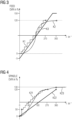
- FIGS. 3 and 4 illustrate the relationship between the respective rotary actuator setting (the angle of rotation) and the OVR value for a conventional rotary actuator in comparison to an assignment made according to the invention.
- Figure 3 illustrates for the FEED-OVR a classic, usually specified by the control manufacturer, "stepped" characteristic curve K1 with “sudden” changes of the FEED-OVR in 23 steps, as is realized, for example, in conventional rotary actuators with fixed end stops and a maximum angle of rotation of 270°.
- characteristic curve K2 is visible, which uses 256 or more steps of a digital encoder, for example, so that the user can no longer see any steps or jumps, neither when operating the machine tool nor from the graphical representation of the characteristic curve, such as from Figure 3 , characteristic curve K2 is visible.
- the characteristic curve K2 is flattened in the area of low feed rates (low OVR values) and in the area of high feed rates (high OVR values).
- this characteristic curve can optionally have an effective angle of rotation range of 6/8 revolutions (270°) or even higher angle ranges up to 360 degrees or even beyond.
- the OVR values for the characteristic curve K2 selected in the example are between 0% and 120%.
- a linear characteristic curve K3 that can be specified by the operator is visible, which uses all 256 available increments of an exemplary rotary actuator in an angular range of the angle of rotation (angle of rotation range) from 0° to 360°.
- the example of the characteristic curve K3 also shows the possibility of setting a negative feed rate of, for example, -5% with the OVR.
- the possible OVR values for the example characteristic curve K3 are therefore in the range between -5% and 150%.
- the characteristic curve K21 shows the "classic" case of a stepped characteristic curve with "jumpy” changes in the feed OVR in 16 steps, distributed over a rotation angle range from 0° to 270°.
- the characteristic curves K22 and K23 are examples of characteristic curves defined by a user.
- K22 establishes a linear relationship between the angle of rotation in a setting range from 0° to 360° and generates associated "SPINDLE-OVR" values in the range from 0% to 120%.
- K23 establishes an at least essentially (from the user's perspective) "smooth", i.e. non-jumpy or non-step-like relationship for angles of rotation starting at 0° and extending beyond 360° and an associated "SPINDLE-OVR" value in the range from 0% to 150%.
- the flattened curve in the range of low or high setting values enables finer adjustment in these ranges.
- Figure 5 shows examples of setting the "FEED-OVR" (feed override).
- Characteristic curve K31 shows a step-like progression of the characteristic curve in a rotation angle range from 0° to 270° and with FEED-OVR values in a range between 0% and 200%.
- Characteristic curve K32 shows a linear smooth curve for a rotation angle range from 0° to 360° with FEED-OVR values in a range between 0% and 200%.
- Characteristic curve K33 shows a smooth, "curved" curve for a rotation angle range from 0° to 360° with FEED-OVR values in a range between 0% and 200%.
- Figure 6 shows an embodiment in which the effective angle of rotation range extends to more than one revolution (360°).
- a first rotation angle range from 0° to 270° there is a linearly increasing relationship to an OVR value in the range from 0% to 120% (see characteristic curve K41).
- a second rotation angle range from 270° to 540° there is a linearly decreasing relationship to an OVR value in the range from 120% to 0% (see characteristic curve K42).
- This alternation between a rising and a falling characteristic curve for value ranges of 270° continues endlessly to the left and right. This results in a linearly falling characteristic curve K43 in the range from -270° to 0°.
- Different gradients or rotation angle ranges could also be specified for the characteristic curves K42 or K43 than for the characteristic curve 41.
- the invention provides for a sensitive variation of the feed or spindle speed, in particular by the fact that the angle of rotation range of the rotary actuator used exceeds 360° (one revolution).
- the problem with this variant is that the operator does not want to turn the OVR 10 times completely in an adjustment range of 10 revolutions, for example, in order to get from a feed rate of 0% to a feed rate of 100%. Not least for this reason, the invention provides for the definition of operating sequences with the help of which certain operating functions, e.g. jumps to certain values, can be triggered.
- a first process step S1 the effect of the feed override, i.e. the change of the OVR value depending on the angle of rotation, is determined by means of an HMI user interface of a CNC control connected to a machine tool.
- a FEED-OVR rotary actuator FEED-OVR
- FEED-OVR FEED-OVR rotary actuator
- a second method step S2 the effect of the spindle override, i.e. the change in the OVR value depending on the angle of rotation of a SPINDLE-OVR rotary actuator (SPINDLE-OVR), is set using the HMI user interface based on a characteristic curve that can be specified by the operator and/or based on at least one operating sequence that can be specified by the operator.
- SPINDLE-OVR SPINDLE-OVR rotary actuator
- a parts program for machining a workpiece using the machine tool is called and started on the CNC control.
- a fourth process step S4 the feed override is set by manual actuation of the FEED-OVR by the user according to the characteristic curve or operating sequence specified in process step S1 and depending on the function currently being performed by the machine tool.
- a spindle override is set by manual actuation of the SPINDLE-OVR by the user according to the characteristic curve or operating sequence specified in process step S2 and depending on the function currently being performed by the machine tool.
- a function of the machine tool in particular a machining of the workpiece by the machine tool, is carried out depending on the set feed override and the set spindle override.
Landscapes
- Engineering & Computer Science (AREA)
- Mechanical Engineering (AREA)
- Human Computer Interaction (AREA)
- Manufacturing & Machinery (AREA)
- Physics & Mathematics (AREA)
- General Physics & Mathematics (AREA)
- Automation & Control Theory (AREA)
- Numerical Control (AREA)
Claims (15)
- Dispositif (31) opératoire d'une commande CNC (30) pour la commande d'une machine-outil (20),dans lequel la machine-outil (20) comprend plusieurs axes (X, Y, Z, A, B, C) de machine, au moyen desquels un outil (1) inséré dans un logement (2) d'outil d'une broche (21) à outil peut être déplacé par rapport à une pièce (5) et/ou peut tourner autour d'un axe (A) de la broche à outil,dans lequel le dispositif (31) opératoire a au moins un actuateur (35, 36) rotatif pouvant être opéré manuellement par un opérateur du dispositif (31) opératoire, pouvant tourner sans fin et par lequel une vitesse d'avance, à laquelle l'outil (1) se déplace par rapport à la pièce (5), et/ou une vitesse de rotation de la broche peut être réglée manuellement par l'opérateur en faisant tourner un bouton à tourner de l'actuateur (35, 36) rotatif,caractérisé en ce quele dispositif (31) opératoire comprend une interface (32) opérateur graphique, au moyen de laquelle l'effet d'une manipulation opératoire effectuée au moyen de l'actuateur (35, 36) rotatif sur la vitesse d'avance et/ou la vitesse de rotation de la broche est réglable.
- Dispositif (31) opératoire suivant la revendication 1, dans lequel par l'actionnement de l'actuateur (35, 36) rotatif, un angle de rotation du bouton à tourner est réglable et dans lequel, pour le réglage de l'effet de la manipulation opératoire, il peut être prescrit une relation entre un angle de rotation et une valeur de réglage en pourcentage, dans lequel la valeur de réglage en pourcentage détermine un rapport entre une vitesse d'avance programmée et/ou une vitesse de rotation programmée de la broche et une vitesse d'avance réelle et/ou une vitesse de rotation réelle de la broche.
- Dispositif (31) opératoire suivant la revendication 1 ou 2, dans lequel par au moins une manipulation opératoire déterminée à l'avance, en particulier une séquence opératoire, une fonction opératoire déterminée à l'avance peut être réalisée et dans lequel une relation entre la fonction opératoire et la valeur de réglage en pourcentage peut être prescrite.
- Dispositif (31) opératoire suivant la revendication 2 ou 3, dans lequel il peut être prescrit une courbe (K1, K2, K3 ; K21, K22, K23 ; K31, K32, K33 ; K41, K42, K43, K44 ; K51, K52 ; K61, K62) caractéristique, qui détermine la relation entre l'angle de rotation et la valeur de réglage en pourcentage.
- Dispositif (31) opératoire suivant la revendication 4, dans lequel il est prescrit dans un menu (40) de sélection, un nombre de courbes caractéristiques, dont l'une peut être choisie par l'opérateur, dans lequel la courbe caractéristique choisie détermine la relation entre l'angle de rotation et la valeur de réglage en pourcentage.
- Dispositif (31) opératoire suivant la revendication 5, dans lequel la courbe caractéristique peut être configurée individuellement, en particulier à l'aide d'un moyen auxiliaire graphique.
- Dispositif (31) opératoire suivant l'une des revendications 4 à 6, dans lequel la courbe caractéristique (K2) a au moins par endroit un tracé (K1) lisse et/ou au moins par endroit en palier.
- Dispositif (31) opératoire suivant l'une des revendications 4 à 7, dans lequel la courbe caractéristique (K23) recouvre une plage d'angle de rotation plus grande que 360° et/ou un angle (K43) de rotation négatif.
- Dispositif (31) opératoire suivant l'une des revendications 4 à 8, dans lequel des plages différentes d'angles de rotation peuvent être affectées à des fonctions opératoires différentes.
- Dispositif (31) opératoire suivant l'une des revendications 2 à 9, dans lequel des plages déterminées d'angles de rotation, en particulier des angles de rotation négatifs, peuvent être affectés à des valeurs de réglage en pourcentage négatives et dans lequel le sens de rotation de la broche ou le sens de déplacement de l'outil dans ces plages d'angles de rotation ou à ces angles de rotation s'inverse par rapport à d'autres plages d'angles de rotation ou d'autres angles de rotation.
- Dispositif (31) opératoire suivant l'une des revendications 3 à 10, dans lequel des manipulations opératoires différentes ou des séquences opératoires différentes peuvent être affectées à des fonctions opératoires différentes.
- Dispositif (31) opératoire suivant la revendication 11, dans lequel des manipulations opératoires ou des séquences opératoires peuvent être conformées et/ou apprises individuellement.
- Dispositif (31) opératoire suivant l'une des revendications précédentes, dans lequel l'effet de la manipulation opératoire effectuée au moyen de l'actuateur rotatif sur la vitesse d'avance et/ou la vitesse de rotation de la broche peut être prescrit, en fonction d'une fonction pouvant être réalisée par la machine-outil (20).
- Procédé pour faire fonctionner une machine-outil (20) commandée au moyen d'une commande CNC (30), qui comprend un dispositif (31) opératoire,dans lequel la machine (20) outil comprend plusieurs axes (X, Y, Z, A, B, C) de machine, au moyen desquels un outil (1) inséré dans un logement (2) d'outil d'une broche (21) à outil est déplacé par rapport à une pièce (5) et/ou tourne autour d'un axe (A) de la broche à outil,dans lequel le dispositif (31) opératoire a au moins un actuateur (35, 36) rotatif pouvant être opéré manuellement par un opérateur du dispositif (31) opératoire, pouvant tourner sans fin et par lequel une vitesse d'avance, à laquelle l'outil (1) se déplace par rapport à la pièce (5), et/ou une vitesse de rotation de la broche est réglée par l'opérateur manuellement par rotation d'un bouton à tourner de l'actuateur (35, 36) rotatif,caractérisé en ce quele dispositif (31) opératoire comprend une interface (32) d'opérateur graphique, au moyen de laquelle on règle l'effet d'un traitement opératoire effectué au moyen de l'actuateur rotatif sur la vitesse d'avance et/ou la vitesse de rotation de la broche,dans lequel on lance un programme, qui est mis à disposition sur la commande CNC et qui prescrit le mouvement de l'outil par rapport à la pièce,dans lequel une manipulation opératoire, effectuée au moyen de l'actuateur rotatif, modifie conformément au réglage, la vitesse d'avance et/ou la vitesse de rotation de la broche.
- Commande CNC ayant un dispositif (31) opératoire suivant l'une des revendications 1 à 13.
Priority Applications (3)
| Application Number | Priority Date | Filing Date | Title |
|---|---|---|---|
| EP21192416.2A EP4137898B1 (fr) | 2021-08-20 | 2021-08-20 | Dispositif de commande pour une commande cnc |
| US17/890,594 US12383999B2 (en) | 2021-08-20 | 2022-08-18 | Operating facility for a CNC control system for controlling a machine tool with a rotary controller |
| CN202210998255.6A CN115708023A (zh) | 2021-08-20 | 2022-08-19 | 用于计算机数控系统的操作设备 |
Applications Claiming Priority (1)
| Application Number | Priority Date | Filing Date | Title |
|---|---|---|---|
| EP21192416.2A EP4137898B1 (fr) | 2021-08-20 | 2021-08-20 | Dispositif de commande pour une commande cnc |
Publications (3)
| Publication Number | Publication Date |
|---|---|
| EP4137898A1 EP4137898A1 (fr) | 2023-02-22 |
| EP4137898B1 true EP4137898B1 (fr) | 2024-04-17 |
| EP4137898C0 EP4137898C0 (fr) | 2024-04-17 |
Family
ID=77431233
Family Applications (1)
| Application Number | Title | Priority Date | Filing Date |
|---|---|---|---|
| EP21192416.2A Active EP4137898B1 (fr) | 2021-08-20 | 2021-08-20 | Dispositif de commande pour une commande cnc |
Country Status (3)
| Country | Link |
|---|---|
| US (1) | US12383999B2 (fr) |
| EP (1) | EP4137898B1 (fr) |
| CN (1) | CN115708023A (fr) |
Families Citing this family (1)
| Publication number | Priority date | Publication date | Assignee | Title |
|---|---|---|---|---|
| CN118884883B (zh) * | 2024-09-29 | 2025-01-03 | 成都秦川物联网科技股份有限公司 | 一种基于工业物联网的数控加工智能监测方法和系统 |
Family Cites Families (16)
| Publication number | Priority date | Publication date | Assignee | Title |
|---|---|---|---|---|
| JP2502063B2 (ja) | 1986-03-31 | 1996-05-29 | 株式会社島津製作所 | 変量調節装置 |
| JP2004102491A (ja) | 2002-09-06 | 2004-04-02 | Sony Corp | リモートコントロール装置、リモートコントロール装置による制御方法及びリモートコントロール装置による制御プログラム |
| DE202004021347U1 (de) | 2003-06-26 | 2007-08-30 | Jura Elektroapparate Ag | Steuerungsvorrichtung für Getränkebereitungsmaschine |
| DE102006052653B4 (de) | 2006-11-08 | 2013-04-11 | Audi Ag | Aktiver Drehsteller und Verfahren zum Einstellen eines Drehmoments bei einem aktiven Drehsteller |
| US7437211B1 (en) | 2007-03-23 | 2008-10-14 | Haas Automation, Inc. | Enhanced remote jog handle |
| JP2010256463A (ja) | 2009-04-22 | 2010-11-11 | Yamaha Corp | パラメータ設定装置 |
| JP5633140B2 (ja) | 2009-11-25 | 2014-12-03 | ヤマハ株式会社 | 音響パラメータの制御装置 |
| DE102010015780A1 (de) * | 2010-04-20 | 2011-10-20 | Carl Zeiss Industrielle Messtechnik Gmbh | Betrieb einer Koordinatenmessmaschine oder einer Werkzeugmaschine |
| CN201699814U (zh) | 2010-06-22 | 2011-01-05 | 山东泰信电子有限公司 | 一种具有旋钮开关的数字电视机顶盒 |
| WO2012098474A2 (fr) | 2011-01-20 | 2012-07-26 | BSH Bosch und Siemens Hausgeräte GmbH | Appareil ménager |
| WO2015194043A1 (fr) * | 2014-06-20 | 2015-12-23 | 株式会社牧野フライス製作所 | Dispositif de commande pour machine-outil |
| EP3130973A1 (fr) * | 2015-08-14 | 2017-02-15 | Siemens Aktiengesellschaft | Panneau de commande de machine destine a la commande d'une machine-outil |
| US9627160B1 (en) | 2016-02-10 | 2017-04-18 | Siemens Aktiengesellschaft | Systems and methods for rotary knob friction adjustment control |
| AT519166A2 (de) | 2016-09-14 | 2018-04-15 | Keba Ag | Steuervorrichtung zum Betreiben einer Werkzeugmaschine, insbesondere einer Fräs- oder Drehmaschine, sowie entsprechende Werkzeugmaschine |
| JP7232243B2 (ja) * | 2017-08-01 | 2023-03-02 | ケバ インダストリアル オートメーション ゲゼルシャフト ミット ベシュレンクテル ハフツング | 産業機械のための制御装置 |
| CN110948286B (zh) | 2019-11-14 | 2020-11-06 | 杭州大天数控机床有限公司 | 加工中心自适应进给切削的方法 |
-
2021
- 2021-08-20 EP EP21192416.2A patent/EP4137898B1/fr active Active
-
2022
- 2022-08-18 US US17/890,594 patent/US12383999B2/en active Active
- 2022-08-19 CN CN202210998255.6A patent/CN115708023A/zh active Pending
Also Published As
| Publication number | Publication date |
|---|---|
| US20230057688A1 (en) | 2023-02-23 |
| US12383999B2 (en) | 2025-08-12 |
| EP4137898A1 (fr) | 2023-02-22 |
| CN115708023A (zh) | 2023-02-21 |
| EP4137898C0 (fr) | 2024-04-17 |
Similar Documents
| Publication | Publication Date | Title |
|---|---|---|
| DE4291618C2 (de) | Computernumerisch-gesteuerte Maschine mit einer manuellen Bedieneinheit zur Steuerung eines programmierten Verfahrwegs | |
| DE60126855T2 (de) | Lehrsteuerpult für Roboter | |
| EP3512669A1 (fr) | Dispositif de commande et procédé de commande pour machines industrielles à entraînement de déplacement commandé | |
| WO2006092406A1 (fr) | Dispositif d'entree et procede d'entree, ainsi que programme informatique correspondant et support d'enregistrement lisible par ordinateur correspondant | |
| DE102008059116B4 (de) | Mikrotom mit konzentrischen Bedienelementen zum Steuern einer Motoreinheit | |
| EP3513261B1 (fr) | Dispositif de commande permettant de faire fonctionner une machine-outil, en particulier une fraiseuse ou un tour, et machine-outil correspondante | |
| DE102017004926A1 (de) | Numerische Steuerung | |
| EP1947538A1 (fr) | Procédé de commande d'un outil mobile, dispositif d'introduction tout comme machine de traitement | |
| DE202017105886U1 (de) | Schalteinrichtung | |
| EP4137898B1 (fr) | Dispositif de commande pour une commande cnc | |
| EP0564538B1 (fr) | Procede pour la commande assistee par ordinateur d'une machine ou d'un processus | |
| DE102004016121B4 (de) | Bedienvorrichtung zum Verfahren mindestens einer Maschinenachse einer Werkzeug- oder Produktionsmaschine | |
| EP4147102B1 (fr) | Fonctionnement d'une machine-outil au moins à deux axes | |
| EP3309635A1 (fr) | Détermination d'un programme de pièce optimisé pour une machine de traitement respective | |
| DE69613518T2 (de) | Rechnergestütztes Entwurfssystem | |
| EP3662345B1 (fr) | Dispositif de commande de machines industrielles | |
| EP3513259B1 (fr) | Dispositif de commande et procédé de commande de machines industrielles comportant des mécanismes de déplacement commandés | |
| WO2005029983A1 (fr) | Unite de commande pour une machine de l'industrie de traitement du tabac | |
| EP3625628B1 (fr) | Structure de régulateur pour entraînement mixte direct / indirect d'un élément de machine | |
| AT520247B1 (de) | Steuervorrichtung für industrielle Maschinen | |
| EP2199882A1 (fr) | Procédé et ordinateur destinés à la production d'un ordre de commande d'un programme de pièces | |
| DE10297548T5 (de) | Eingabe/Ausgabe-Bedienerschnittstellensteuerung mit Bestimmung der Existenz von möglichen Bedingungen zur Aufnahme von unerwünschten Befehlssignalen | |
| DE4417424A1 (de) | Steuerung für einen Schrittantrieb | |
| EP2818950A2 (fr) | Appareil pour changer un paramètre d'un dispositif d'usinage en utilisant une interface utilisateur graphique | |
| DE102018004924A1 (de) | Steuerung |
Legal Events
| Date | Code | Title | Description |
|---|---|---|---|
| PUAI | Public reference made under article 153(3) epc to a published international application that has entered the european phase |
Free format text: ORIGINAL CODE: 0009012 |
|
| STAA | Information on the status of an ep patent application or granted ep patent |
Free format text: STATUS: THE APPLICATION HAS BEEN PUBLISHED |
|
| AK | Designated contracting states |
Kind code of ref document: A1 Designated state(s): AL AT BE BG CH CY CZ DE DK EE ES FI FR GB GR HR HU IE IS IT LI LT LU LV MC MK MT NL NO PL PT RO RS SE SI SK SM TR |
|
| STAA | Information on the status of an ep patent application or granted ep patent |
Free format text: STATUS: REQUEST FOR EXAMINATION WAS MADE |
|
| 17P | Request for examination filed |
Effective date: 20230803 |
|
| RBV | Designated contracting states (corrected) |
Designated state(s): AL AT BE BG CH CY CZ DE DK EE ES FI FR GB GR HR HU IE IS IT LI LT LU LV MC MK MT NL NO PL PT RO RS SE SI SK SM TR |
|
| GRAP | Despatch of communication of intention to grant a patent |
Free format text: ORIGINAL CODE: EPIDOSNIGR1 |
|
| STAA | Information on the status of an ep patent application or granted ep patent |
Free format text: STATUS: GRANT OF PATENT IS INTENDED |
|
| INTG | Intention to grant announced |
Effective date: 20231220 |
|
| GRAS | Grant fee paid |
Free format text: ORIGINAL CODE: EPIDOSNIGR3 |
|
| GRAA | (expected) grant |
Free format text: ORIGINAL CODE: 0009210 |
|
| STAA | Information on the status of an ep patent application or granted ep patent |
Free format text: STATUS: THE PATENT HAS BEEN GRANTED |
|
| AK | Designated contracting states |
Kind code of ref document: B1 Designated state(s): AL AT BE BG CH CY CZ DE DK EE ES FI FR GB GR HR HU IE IS IT LI LT LU LV MC MK MT NL NO PL PT RO RS SE SI SK SM TR |
|
| REG | Reference to a national code |
Ref country code: GB Ref legal event code: FG4D Free format text: NOT ENGLISH |
|
| REG | Reference to a national code |
Ref country code: CH Ref legal event code: EP |
|
| REG | Reference to a national code |
Ref country code: IE Ref legal event code: FG4D Free format text: LANGUAGE OF EP DOCUMENT: GERMAN Ref country code: DE Ref legal event code: R096 Ref document number: 502021003358 Country of ref document: DE |
|
| U01 | Request for unitary effect filed |
Effective date: 20240417 |
|
| U07 | Unitary effect registered |
Designated state(s): AT BE BG DE DK EE FI FR IT LT LU LV MT NL PT SE SI Effective date: 20240422 |
|
| U20 | Renewal fee for the european patent with unitary effect paid |
Year of fee payment: 4 Effective date: 20240819 |
|
| PG25 | Lapsed in a contracting state [announced via postgrant information from national office to epo] |
Ref country code: IS Free format text: LAPSE BECAUSE OF FAILURE TO SUBMIT A TRANSLATION OF THE DESCRIPTION OR TO PAY THE FEE WITHIN THE PRESCRIBED TIME-LIMIT Effective date: 20240817 |
|
| PG25 | Lapsed in a contracting state [announced via postgrant information from national office to epo] |
Ref country code: HR Free format text: LAPSE BECAUSE OF FAILURE TO SUBMIT A TRANSLATION OF THE DESCRIPTION OR TO PAY THE FEE WITHIN THE PRESCRIBED TIME-LIMIT Effective date: 20240417 |
|
| PG25 | Lapsed in a contracting state [announced via postgrant information from national office to epo] |
Ref country code: GR Free format text: LAPSE BECAUSE OF FAILURE TO SUBMIT A TRANSLATION OF THE DESCRIPTION OR TO PAY THE FEE WITHIN THE PRESCRIBED TIME-LIMIT Effective date: 20240718 |
|
| PG25 | Lapsed in a contracting state [announced via postgrant information from national office to epo] |
Ref country code: ES Free format text: LAPSE BECAUSE OF FAILURE TO SUBMIT A TRANSLATION OF THE DESCRIPTION OR TO PAY THE FEE WITHIN THE PRESCRIBED TIME-LIMIT Effective date: 20240417 |
|
| PG25 | Lapsed in a contracting state [announced via postgrant information from national office to epo] |
Ref country code: PL Free format text: LAPSE BECAUSE OF FAILURE TO SUBMIT A TRANSLATION OF THE DESCRIPTION OR TO PAY THE FEE WITHIN THE PRESCRIBED TIME-LIMIT Effective date: 20240417 |
|
| PG25 | Lapsed in a contracting state [announced via postgrant information from national office to epo] |
Ref country code: PL Free format text: LAPSE BECAUSE OF FAILURE TO SUBMIT A TRANSLATION OF THE DESCRIPTION OR TO PAY THE FEE WITHIN THE PRESCRIBED TIME-LIMIT Effective date: 20240417 Ref country code: NO Free format text: LAPSE BECAUSE OF FAILURE TO SUBMIT A TRANSLATION OF THE DESCRIPTION OR TO PAY THE FEE WITHIN THE PRESCRIBED TIME-LIMIT Effective date: 20240717 Ref country code: IS Free format text: LAPSE BECAUSE OF FAILURE TO SUBMIT A TRANSLATION OF THE DESCRIPTION OR TO PAY THE FEE WITHIN THE PRESCRIBED TIME-LIMIT Effective date: 20240817 Ref country code: HR Free format text: LAPSE BECAUSE OF FAILURE TO SUBMIT A TRANSLATION OF THE DESCRIPTION OR TO PAY THE FEE WITHIN THE PRESCRIBED TIME-LIMIT Effective date: 20240417 Ref country code: GR Free format text: LAPSE BECAUSE OF FAILURE TO SUBMIT A TRANSLATION OF THE DESCRIPTION OR TO PAY THE FEE WITHIN THE PRESCRIBED TIME-LIMIT Effective date: 20240718 Ref country code: ES Free format text: LAPSE BECAUSE OF FAILURE TO SUBMIT A TRANSLATION OF THE DESCRIPTION OR TO PAY THE FEE WITHIN THE PRESCRIBED TIME-LIMIT Effective date: 20240417 Ref country code: RS Free format text: LAPSE BECAUSE OF FAILURE TO SUBMIT A TRANSLATION OF THE DESCRIPTION OR TO PAY THE FEE WITHIN THE PRESCRIBED TIME-LIMIT Effective date: 20240717 |
|
| REG | Reference to a national code |
Ref country code: DE Ref legal event code: R097 Ref document number: 502021003358 Country of ref document: DE |
|
| PG25 | Lapsed in a contracting state [announced via postgrant information from national office to epo] |
Ref country code: CZ Free format text: LAPSE BECAUSE OF FAILURE TO SUBMIT A TRANSLATION OF THE DESCRIPTION OR TO PAY THE FEE WITHIN THE PRESCRIBED TIME-LIMIT Effective date: 20240417 |
|
| PG25 | Lapsed in a contracting state [announced via postgrant information from national office to epo] |
Ref country code: SK Free format text: LAPSE BECAUSE OF FAILURE TO SUBMIT A TRANSLATION OF THE DESCRIPTION OR TO PAY THE FEE WITHIN THE PRESCRIBED TIME-LIMIT Effective date: 20240417 Ref country code: RO Free format text: LAPSE BECAUSE OF FAILURE TO SUBMIT A TRANSLATION OF THE DESCRIPTION OR TO PAY THE FEE WITHIN THE PRESCRIBED TIME-LIMIT Effective date: 20240417 |
|
| PG25 | Lapsed in a contracting state [announced via postgrant information from national office to epo] |
Ref country code: SM Free format text: LAPSE BECAUSE OF FAILURE TO SUBMIT A TRANSLATION OF THE DESCRIPTION OR TO PAY THE FEE WITHIN THE PRESCRIBED TIME-LIMIT Effective date: 20240417 |
|
| PG25 | Lapsed in a contracting state [announced via postgrant information from national office to epo] |
Ref country code: SM Free format text: LAPSE BECAUSE OF FAILURE TO SUBMIT A TRANSLATION OF THE DESCRIPTION OR TO PAY THE FEE WITHIN THE PRESCRIBED TIME-LIMIT Effective date: 20240417 Ref country code: SK Free format text: LAPSE BECAUSE OF FAILURE TO SUBMIT A TRANSLATION OF THE DESCRIPTION OR TO PAY THE FEE WITHIN THE PRESCRIBED TIME-LIMIT Effective date: 20240417 Ref country code: RO Free format text: LAPSE BECAUSE OF FAILURE TO SUBMIT A TRANSLATION OF THE DESCRIPTION OR TO PAY THE FEE WITHIN THE PRESCRIBED TIME-LIMIT Effective date: 20240417 Ref country code: CZ Free format text: LAPSE BECAUSE OF FAILURE TO SUBMIT A TRANSLATION OF THE DESCRIPTION OR TO PAY THE FEE WITHIN THE PRESCRIBED TIME-LIMIT Effective date: 20240417 |
|
| PLBE | No opposition filed within time limit |
Free format text: ORIGINAL CODE: 0009261 |
|
| STAA | Information on the status of an ep patent application or granted ep patent |
Free format text: STATUS: NO OPPOSITION FILED WITHIN TIME LIMIT |
|
| 26N | No opposition filed |
Effective date: 20250120 |
|
| REG | Reference to a national code |
Ref country code: CH Ref legal event code: PL |
|
| PG25 | Lapsed in a contracting state [announced via postgrant information from national office to epo] |
Ref country code: CH Free format text: LAPSE BECAUSE OF NON-PAYMENT OF DUE FEES Effective date: 20240831 Ref country code: MC Free format text: LAPSE BECAUSE OF FAILURE TO SUBMIT A TRANSLATION OF THE DESCRIPTION OR TO PAY THE FEE WITHIN THE PRESCRIBED TIME-LIMIT Effective date: 20240417 |
|
| PG25 | Lapsed in a contracting state [announced via postgrant information from national office to epo] |
Ref country code: IE Free format text: LAPSE BECAUSE OF NON-PAYMENT OF DUE FEES Effective date: 20240820 |
|
| U20 | Renewal fee for the european patent with unitary effect paid |
Year of fee payment: 5 Effective date: 20250820 |
|
| PG25 | Lapsed in a contracting state [announced via postgrant information from national office to epo] |
Ref country code: CY Free format text: LAPSE BECAUSE OF FAILURE TO SUBMIT A TRANSLATION OF THE DESCRIPTION OR TO PAY THE FEE WITHIN THE PRESCRIBED TIME-LIMIT; INVALID AB INITIO Effective date: 20210820 |
|
| PG25 | Lapsed in a contracting state [announced via postgrant information from national office to epo] |
Ref country code: HU Free format text: LAPSE BECAUSE OF FAILURE TO SUBMIT A TRANSLATION OF THE DESCRIPTION OR TO PAY THE FEE WITHIN THE PRESCRIBED TIME-LIMIT; INVALID AB INITIO Effective date: 20210820 |