EP3662535B1 - Antenne für ein elektronisches element eines reifens - Google Patents
Antenne für ein elektronisches element eines reifens Download PDFInfo
- Publication number
- EP3662535B1 EP3662535B1 EP18752831.0A EP18752831A EP3662535B1 EP 3662535 B1 EP3662535 B1 EP 3662535B1 EP 18752831 A EP18752831 A EP 18752831A EP 3662535 B1 EP3662535 B1 EP 3662535B1
- Authority
- EP
- European Patent Office
- Prior art keywords
- antenna
- radiating
- electronic
- electronic member
- radiating antenna
- Prior art date
- Legal status (The legal status is an assumption and is not a legal conclusion. Google has not performed a legal analysis and makes no representation as to the accuracy of the status listed.)
- Active
Links
Images


Classifications
-
- B—PERFORMING OPERATIONS; TRANSPORTING
- B60—VEHICLES IN GENERAL
- B60C—VEHICLE TYRES; TYRE INFLATION; TYRE CHANGING; CONNECTING VALVES TO INFLATABLE ELASTIC BODIES IN GENERAL; DEVICES OR ARRANGEMENTS RELATED TO TYRES
- B60C19/00—Tyre parts or constructions not otherwise provided for
-
- H—ELECTRICITY
- H01—ELECTRIC ELEMENTS
- H01Q—ANTENNAS, i.e. RADIO AERIALS
- H01Q1/00—Details of, or arrangements associated with, antennas
- H01Q1/12—Supports; Mounting means
- H01Q1/22—Supports; Mounting means by structural association with other equipment or articles
- H01Q1/2208—Supports; Mounting means by structural association with other equipment or articles associated with components used in interrogation type services, i.e. in systems for information exchange between an interrogator/reader and a tag/transponder, e.g. in Radio Frequency Identification [RFID] systems
- H01Q1/2216—Supports; Mounting means by structural association with other equipment or articles associated with components used in interrogation type services, i.e. in systems for information exchange between an interrogator/reader and a tag/transponder, e.g. in Radio Frequency Identification [RFID] systems used in interrogator/reader equipment
-
- H—ELECTRICITY
- H01—ELECTRIC ELEMENTS
- H01Q—ANTENNAS, i.e. RADIO AERIALS
- H01Q1/00—Details of, or arrangements associated with, antennas
- H01Q1/12—Supports; Mounting means
- H01Q1/22—Supports; Mounting means by structural association with other equipment or articles
- H01Q1/2208—Supports; Mounting means by structural association with other equipment or articles associated with components used in interrogation type services, i.e. in systems for information exchange between an interrogator/reader and a tag/transponder, e.g. in Radio Frequency Identification [RFID] systems
- H01Q1/2241—Supports; Mounting means by structural association with other equipment or articles associated with components used in interrogation type services, i.e. in systems for information exchange between an interrogator/reader and a tag/transponder, e.g. in Radio Frequency Identification [RFID] systems used in or for vehicle tyres
-
- H—ELECTRICITY
- H01—ELECTRIC ELEMENTS
- H01Q—ANTENNAS, i.e. RADIO AERIALS
- H01Q1/00—Details of, or arrangements associated with, antennas
- H01Q1/36—Structural form of radiating elements, e.g. cone, spiral, umbrella; Particular materials used therewith
- H01Q1/362—Structural form of radiating elements, e.g. cone, spiral, umbrella; Particular materials used therewith for broadside radiating helical antennas
Definitions
- the invention relates to the field of electronic components for tires.
- Each antenna has a substantially helical shape.
- Each antenna comprises a steel core coated directly with a brass coating which is an alloy of copper and zinc whose proportions are respectively of the order of 75% and 25%.
- the electromagnetic conduction for such an antenna is carried out mainly by a skin effect, that is to say that it is mainly ensured in the external layers of the antenna.
- This skin thickness is in particular a function of the frequency of the radiation and of the constituent material of the conduction layer.
- the skin thickness is 2.1 ⁇ m for silver, 2.2 ⁇ m for copper, 4.4 ⁇ m for brass.
- a bare filiform core unwound from a storage coil is shaped by plastically deforming it to give it a helical shape. Then, the bare helical core is coated with the brass coating. The coating step is carried out in an electrolytic bath.
- the thickness of the coating layer must not be less than 4.4 micrometers.
- the subject of the invention is a half-wave dipole radiating antenna, for an electronic component, the length of which is adapted to operate in the frequency range between 860 MHz and 960 MHz, comprising a core coated with a brass coating, the antenna being intended to be incorporated into a mass of rubber, in particular of a tire, characterized in that the thickness of the brass coating is between 0.5 and 4.0 ⁇ m.
- the frequency range between 860 MHz and 960 MHz constitutes the highest usable frequency frequency range for these electronic components integrated into a mass of rubber such as a tire.
- the length of the half-wave radiating antenna being inversely proportional to the communication frequency in its medium in order to operate optimally, this frequency range is used in order to reduce the length of the antenna as much as possible and thus facilitate integration.
- the antenna and the electronic component associated with it within the tire Finally, the radiating antenna is optimized in the far field, allowing radiofrequency communication with an external reader several meters away.
- the thickness of the brass coating is between 1 and 2 ⁇ m. and most preferably, the brass coating thickness ranges from 1.2 to 1.8 ⁇ m
- the external brass coating which acts as a conduction layer enables an electromagnetic signal to be conducted by skin effect between the antenna and the electronic device which is connected thereto.
- the thickness of the coating is conditioned by the manufacturing process of this coating. It is fairly easy and inexpensive for the radio frequency antennae used in electronic components intended to be integrated into a tire to produce a coating layer extending from 1.2 to 1.8 ⁇ m.
- the coating step is conventionally carried out in an electrolytic bath.
- the core of the antenna is made of steel.
- the diameter of the core wire is between 0.15 and 0.32 mm.
- the carbon content of the steel of the core is less than 1% and preferably between 0.5 and 0.8%.
- This low carbon content is very positive for the mechanical properties of the steel.
- the purity of the steel is improved, that is to say that there are fewer impurities and this increases the rigidity of the antenna while facilitating its shaping without breaks.
- the antenna may also include an outer layer for adhesion of the antenna to the rubber coating the brass coating or conduction layer. As its name suggests, this layer ensures a lasting intimate contact between the adjacent rubber mass and the antenna after a step of crosslinking the rubber mass.
- the outer adhesion layer directly coats the conduction layer.
- the conduction layer may be coated with one or more adhesion layers.
- the adhesion layer can include a non-metallic and water-based adhesive.
- This non-metallic adhesive may comprise two layers applied successively and the total thickness of which is between 1 and 40 ⁇ m.
- Chemlok 8210 and 8007 from Lord Corp. Their deposition is preferably carried out by spraying to obtain good uniformity with a reduced thickness.
- the adhesive layer can also be imide-based. It is preferably also applied by spraying, which makes it possible to obtain a thickness of the order of 2 ⁇ m.
- One such adhesive is Chemlok 6411 or Chemosil 411-NL.
- the antenna comprises at least one helical portion.
- the antenna is preferably intended to be integrated into a tire. During operation of the tire, the latter is subjected to stresses and deformations which are transmitted to the antenna.
- the helical shape makes it possible to improve the endurance of the antenna with respect to the stresses to which the antenna is subjected. Indeed, the helical shape gives the antenna a flexibility allowing it to deform without risk of breaking which on the one hand would render the electronic function inoperative and on the other hand would present a risk of damaging the tire.
- the outer diameter of the helical portion is between 0.8 and 1.5 mm and the pitch of the helical portion is between 5 and 15 turns per centimeter.
- the invention also relates to an electronic component comprising a radiofrequency transponder with a radiating antenna connected to the electronic component, the antenna being as defined above.
- Radiofrequency transponders usually comprise an electronic chip and a radiating antenna capable of communicating with an external radiofrequency reader.
- the radiating antenna comprising two helical antenna sections
- the electronic chip is galvanically connected to the two helical antenna sections.
- the radiofrequency transponder further comprises a primary antenna electrically connected to the electronic chip, in which the primary antenna is inductively coupled to the radiating antenna, and in which the radiating antenna is a dipole antenna consisting of a single strand coil spring.
- This second embodiment has the advantage of mechanically dissociating the radiating antenna from the electronic components of the transponder and thus of eliminating the weak point of the usual transponders, namely the zone for fixing the antenna sections on the support of the electronic chip.
- the integration of such an electronic component in a tire makes it possible to reduce the risks of deterioration of the component due to its structure while improving the radiocommunication performance and minimizing the risks associated with the physical integrity of the tire.
- the deterioration of the electronic component generally results from failures in the electrical connections existing between the radiating communication antenna and the electronic part of the component.
- no mechanical connection is made since the transfer of energy between the communication antenna and the electronic chip is done by electromagnetic field via a primary antenna.
- the primary antenna is not subject to this constraint.
- it is generally smaller in size, making it possible to easily withstand the deformations of the tire without generating excessive mechanical stresses within its galvanic junction with the electronic chip.
- the flexible nature of the radiating antenna limits the risks of damage to the zone of the tire close to the transponder.
- the introduction of the primary antenna makes it possible to dissociate antagonistic functions between the dimension of the radiating antenna and the electrical impedance of the electronic part of the component.
- the dimensioning of the radiating antenna then follows the sole criterion of the communication frequency of the electronic component. The assembly tends to improve the radiocommunication performance of the electronic component.
- the radiating antenna defining a first longitudinal axis
- the primary antenna is a coil having at least one turn defining a second longitudinal axis which is circumscribed in a cylinder whose axis of revolution is parallel to the second longitudinal axis and whose diameter is between one-third and three times, preferably between one-half and two times, the average diameter of the coil spring of the radiating antenna.
- the primary antenna being a loop antenna
- the transfer of energy between the radiating antenna and the primary antenna is mainly carried out by inductive coupling. This then imposes a certain proximity (to limit the air gap between the two antennas) between the two antennas requiring a dimensioning of the coil of the primary antenna with respect to the radiating antenna to ensure sufficient energy transfer efficiency for have the desired radio communication quality.
- the primary antenna can advantageously be of smaller diameter than that of the radiating antenna, in this case the entire electronic part of the transponder is inserted into the radiating antenna and the assembly is particularly robust in an environment such as than that of a tire.
- the antenna can also be of larger diameter than that of the radiating antenna, this case is particularly advantageous when it is desired to add to the radio frequency transponder other electronic components, active or passive, to carry out additional functions, for example of tire condition monitoring.
- the radiating antenna having a central zone between two lateral zones and the primary antenna having a median plane perpendicular to the second longitudinal axis, the first and second longitudinal axes are parallel to each other and the median plane of the The primary antenna is arranged in the central zone of the radiating antenna.
- the distance between the radiating and primary antennas is constant along the longitudinal axes of these antennas, thus optimizing at the level of each element of length of the primary antenna an equivalent energy transfer.
- the magnetic field created by a coil traversed by an electric current being maximum at the center of the length of the coil (in the case of a ⁇ /2 antenna)
- the primary antenna is arranged inside the single-strand helical spring of the radiating antenna.
- the electronic component may consist of a radiofrequency transponder. It can also consist of a radiofrequency transponder encapsulated in a mass of electrically insulating coating rubber.
- this antenna be embedded in a mass of electrically insulating rubber coating. It is thus possible to use a semi-finished product consisting of a radiofrequency transponder embedded in a mass of electrically insulating rubber to place it in the structure of the tire during its manufacture in the chosen place.
- radiofrequency transponder directly between two compounds of the tire when the latter, due to their formulation, are electrically insulating.
- the tensile modulus of the coating gum mass is less than or equal to the tensile modulus of the adjacent rubber mixtures.
- the relative dielectric constant of the mass of rubber coating is lower than the relative dielectric constant of the adjacent rubber mixtures.
- the outer layer of the antenna may be constituted by the layer of brass and the rubbery mixture of the mass of coating rubber may be able to develop strong adhesion with the layer of brass after vulcanization.
- This embodiment is particularly advantageous in the case where the antenna of the radiofrequency transponder of the electronic component is mechanically separated from the electronic chip.
- Such masses of coating gums have, for example, a formulation comprising cobalt salts.
- the invention relates more particularly to tires intended to be fitted to vehicles of the passenger car type, SUV (“Sport Utility Vehicles”), two-wheelers (in particular motorcycles), airplanes, such as industrial vehicles chosen from vans, “Heavyweight” - c i.e. metro, bus, road transport vehicles (trucks, tractors, trailers), off-road vehicles such as agricultural or civil engineering machinery - other transport or handling vehicles.
- SUV Sport Utility Vehicles
- two-wheelers in particular motorcycles
- airplanes such as industrial vehicles chosen from vans, “Heavyweight” - c i.e. metro, bus, road transport vehicles (trucks, tractors, trailers), off-road vehicles such as agricultural or civil engineering machinery - other transport or handling vehicles.
- any interval of values designated by the expression “between a and b” represents the range of values going from more than a to less than b (i.e. limits a and b excluded) while any interval of values denoted by the expression “from a to b” means the range of values going from a to b (that is to say including the strict limits a and b).
- rubbery rubber “rubbery mixture”, “rubber” and “mixture” are used in an equivalent manner to identify rubbery constituents of a tire.
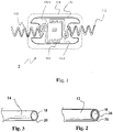
- the radiofrequency transponder of the electronic component 2 is a usual radiofrequency transponder, as described in the document WO2009134243A1 .
- This transponder 2 comprises an electronic chip 120 fixed on a support or PCB (printed circuit board) 102 and galvanically connected via conductive tracks 104, 130A and 130B to two half-antennas 110 and 112. steel wire.
- the contour 150 refers to layers of non-conductive encapsulating rubbery gum that cover the PCB, the electronic chip and at least part of the two half-antennas.
- the two antennas 110 and 112 being identical, a single antenna 110 will be described with reference to the figures 2 and 3 .
- the two antennas 110 and 112 constitute a dipole antenna.
- the antenna 110 has a substantially helical shape and has a length, an outside diameter and a helix pitch defined according to the conditions of use of the electronic component.
- the pitch of the propeller may be between 5 and 15 turns per centimeter, the outside diameter between 0.8 and 1.5 mm and the length of the order of 25 mm. This combination of characteristics is particularly useful in the case of operation of an electronic component in a tire at UHF frequencies in the frequency band between 860 MHz and 960 MHz.
- the antenna 110 is made from a steel wire 12 which comprises a steel core 18 having an outer diameter of between 0.15 and 0.32 mm.
- the wire 12 also includes a conduction layer 26 directly coating the core 18.
- the conduction layer 26 consists brass and is in contact with the core 18.
- the layer 26 has a thickness of between 1 and 2 micrometers. Although the skin thickness for brass at 915MHz is 4.4 micrometers, a layer of brass with a thickness between 1 to 2 micrometers allows sufficient radio frequency operation in the frequency range between 860 and 960 MHz. .
- wire 12 also includes a second adhesion layer 28 directly coating brass layer 26.
- Layer 28 includes a non-metallic, water-based adhesive.
- An example of such an adhesive is Chemlok 8210 and 8007 from Lord Corp.
- the primary and the secondary are successively applied to the wire 12, preferably by spraying.
- the total thickness of layer 28 is between 1 and 40 ⁇ m.
- Spray deposition provides good uniformity with reduced thickness.
- the adhesive layer can also be imide-based. It is preferably also applied by spraying, which makes it possible to obtain a thickness of the order of 2 ⁇ m.
- One such adhesive is Chemlok 6411 or Chemosil 411-NL.
- the adhesion layer ensures a lasting intimate contact between the adjacent rubber mass and the antenna after a step of crosslinking the rubber mass.
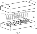
- the picture 3 presents a second embodiment of a wire 14 intended to constitute an antenna 110.
- the outer layer of the wire 14 is constituted by the conduction layer of brass 26 and there is no additional layer of membership.
- the mass of coating gum which is used to coat the electronic component and the antenna 110 which has a formulation capable of constituting after vulcanization a solid interface with the antenna.
- Such formulations include in particular cobalt salts as well known to those skilled in the art.
- the figure 4 shows an exploded view of an electronic component 2.
- This component 2 comprises a radiofrequency transponder 1 embedded between two layers 3a and 3b of a mixture of non-vulcanized electrically insulating rubbery gum.
- Such an electronic component is a semi-finished product capable of being integrated into the structure of a tire during the manufacture of the latter.
- the rubbery coating mixture contains 100 phr (parts per 100 parts of elastomer by mass) of polymer such as EPDM (ethylene propylene diene monomer rubber), butyl rubber, neoprene or of diene elastomer such as SBR (styrene-butadiene rubber), polybutadiene, natural rubber, or polyisoprene.
- EPDM ethylene propylene diene monomer rubber
- butyl rubber neoprene or of diene elastomer
- SBR styrene-butadiene rubber
- polybutadiene polybutadiene
- natural rubber or polyisoprene
- the baked stiffness of the coating mix is preferably less than or close to that of adjacent mixes.
- the radiofrequency transponder 1 of the electronic component 2 as presented at the figure 4 corresponds to a second embodiment of the electronic component 2 which will now be described.
- the radiofrequency transponder 1 according to the second embodiment of the electronic component 2 comprises an electronic chip 22 and a half-wave radiating antenna 10 able to communicate with an external radiofrequency reader. It further comprises a primary antenna 24 electrically connected to the electronic chip 22 and inductively coupled to the radiating antenna 10.
- the radiating antenna is a dipole antenna consisting of a single-strand helical spring defining a first longitudinal axis.
- the figure 5 presents a radiofrequency transponder 1 in a configuration where the electronic part 20 is located inside the radiating antenna 10.
- the geometric shape of the electronic part 20 is circumscribed in a cylinder whose diameter is less than or equal to the internal diameter 13 of the helical spring 10. The threading of the electronic part 20 into the half-wave radiating antenna 10 is thereby facilitated.
- the median plane 21 of the primary antenna is located in the central zone of the radiating antenna and substantially superimposed on the median plane 19 of the radiating antenna 10.
- the figure 6 presents a radiofrequency transponder 1 in a configuration where the electronic part 20 is located outside the radiating antenna 10.
- the geometric shape of the electronic part 20 presents a cylindrical cavity 25 whose diameter is greater than or equal to the external diameter 15 half wave radiating antenna10. The threading of the half-wave radiating antenna 10 into the cylindrical cavity 25 of the electronic part is thus facilitated.
- the median plane 21 of the primary antenna is located in the central zone of the radiating antenna and substantially in the median plane 19 of the radiating antenna 10.
- the figure 7 has a radiating antenna 10 consisting of the steel wire 12 of the figure 2 , or wire picture 3 , which has been plastically deformed to form a coil spring having an axis of revolution 11.
- This steel wire is coated with a brass conduction layer 26 covered in the case of the figure 2 an adhesive layer 28.
- the steel wire can be coated with these layers and then shaped; alternatively it can also be shaped and then coated.
- the coil spring is defined first by a wrap diameter of the coated wire and a helix pitch.
- the length 17 of the spring 10 here corresponds to the half-wavelength of the transmission signal from the radiofrequency transponder 1 in a rubbery mass.
- the figure 8 presents the electronic part 20 of a radiofrequency transponder 1 intended for a configuration where the electronic part 20 is located inside the radiating antenna 10.
- the electronic part 20 comprises an electronic chip 22 and a primary antenna 24 electrically connected to the electronic chip 22 via a printed circuit 26.
- the primary antenna here consists of a micro coil CMS (acronym for Surface Mounted Component) having an axis of symmetry 23.
- the median plane 21 of the primary antenna is determined, defined by a normal parallel to the axis of symmetry 23 of the CMS coil and separating the coil into two equal parts.
- the electrical connection between the components on the printed circuit is made using copper tracks terminated by copper pads 27.
- the electrical connection of the components on the printed circuit is made using the so-called "wire bonding" technique by means of gold wires 28 between the component and the pads 27.
- the assembly consisting of the printed circuit 26, the chip electronics 22 of the primary antenna 24 is embedded in a rigid mass 29 of electrically insulating high-temperature epoxy resin constituting the electronic part 20 of the radiofrequency transponder 1.
- This radio frequency transponder 1 has the advantage of being much more mechanically resistant than the usual transponders and thus is particularly suitable for severe use such as encountered with tires capable of running flat.
- the figure 9 illustrates in partial axial section a tire capable of running flat and fitted with an electronic component according to the invention.
- This figure indicates the axial X, circumferential C and radial Z directions as well as the median plane EP (plane perpendicular to the axis of rotation of the tire which is located halfway between the two beads of the tire and passes through the middle of the crown reinforcement) and the axis of rotation XX of the tire 30.
- EP plane perpendicular to the axis of rotation of the tire which is located halfway between the two beads of the tire and passes through the middle of the crown reinforcement
- This figure also indicates the section height SH of the tire, that is to say the radial distance between the nominal diameter of the mounting rim of the tire NRD and the radially outermost part of the tread of the tire.
- the nominal diameter of the mounting rim of the tire is taken to be the diameter of the tire as indicated by its dimension.
- the tire is shown free, not mounted on a rim and such that the width between the two beads is reduced to the width of the nominal ETRTO rim.
- the term “axially external” means an axial direction directed towards the outside of the tire and the term “axially internal” means an axial direction directed towards the median plane EP of the tire.
- the tire 30 illustrated in figure 9 is a tire suitable for running flat, but it is chosen for purely illustrative purposes and the antennas and electronic components described can be integrated into and on the surface of all types of tires as indicated above.
- This tire 30 suitable for running flat comprises a crown 32 reinforced by a crown reinforcement or belt 36, a sidewall 33 and a bead 34, the bead 34 being reinforced with a bead wire 35.
- the crown reinforcement 36 is surmounted radially externally a rubbery tread 39.
- a constituted carcass reinforcement 37 is wound around the bead wire 35 in the bead 34, the upturn 38 of this reinforcement 37 being for example disposed towards the outside of the tire 30.
- the reinforcement carcass 37 is in a manner known per se made up of at least one ply reinforced by so-called "radial” cables, for example here textiles, that is to say that these cables are arranged practically parallel to each other and are extend from one bead to the other so as to form an angle of between 80° and 90° with the median circumferential plane EP.
- a layer of sealed inner rubber 40 (in English “inner liner") extends from one bead to the other radially internally relative to the carcass reinforcement 37.
- the bead 34 comprises a protective rubber (or “protector”) 42 adapted to be in contact with the surface of a rim. It also comprises a first stuffing rubber 46 extending radially outwardly relative to the bead wire 35.
- the tire 30 is able to run flat due to the presence of a sidewall insert 44 disposed axially internally relative to the carcass reinforcement 33.
- This insert 44 enables the structure of the tire to support the load at zero pressure.
- the order of magnitude of the modulus of extension of a rubbery rubber of a sidewall insert is of the order of twice the value of the modulus of a sidewall rubber or more.
- the side insert 44 of the figure 9 comprises an electronic component 2 disposed at a radial distance D1 from point H.
- Point H is one of the points closest to the axis of rotation XX.
- the distance D must be greater than D0 equal to 20 mm so as not to penalize the quality of communication between the electronic component and an external reader. This distance is greater than the height of a usual rim hook which is 17.5 mm.
- the electronic component is preferably placed in the semi-finished sidewall insert before its incorporation into the tire blank.
- the side insert 44 in the example of the figure 9 , consists of two masses of rubbers 441 and 442 axially adjacent to each other and the electronic components 2 and 2a are placed at the interface between the two rubbers 441 and 442.
- This embodiment facilitates the precise and reproducible positioning of the electronic components during the manufacture of the tire.
- the figure 9 illustrates the zone Z of the section height SH of the tire in which it is preferable to position the electronic components. This zone Z extends from 20 to 70% of SH. Electronic component 2 is placed at about 25% SH and component 2a at 60%.
- the electronic organ is placed at about 45% SH.
- the table below presents the results of radio frequency transponder communication power tests carried out with antennas whose thickness of the conduction layer is variable.
- the power returned by the radiofrequency transponder to an external reader is evaluated following the energy emitted by this same external reader.
- This external reader being positioned at a distance of approximately 1 meter from the radiofrequency transponder emits an identical exciter signal for all the samples.
- the power received by the external reader is evaluated as the integral of the response spectrum over the frequency range. Power deviations are expressed on a logarithmic scale.
- the reference corresponds to a radiofrequency transponder as presented in the document WO 2012020202 A1 .
- the antenna has a 4 ⁇ m thick copper conduction layer coated with a 0.5 ⁇ m thick chemical insulation layer to protect the copper from adjacent rubber compounds. All the antennas also include an aqueous-based adhesion layer as previously described.
- This reference transponder is incorporated daily into the structure of truck tires.
- the T1 transponder has a 0.226 mm diameter antenna and a 1.5 ⁇ m thick brass layer.
- the decrease in communication power is 0.8 dBm. This reduction is significant but does not in any way call into question the use of such an antenna wire in an application inside a tire. In fact, this corresponds to approximately an 8% reduction in the optimal reading distance. This shows that contrary to what was commonly accepted, a conduction layer with a thickness of less than 4.4 ⁇ m in the case of brass is quite usable.
- Examples T1 and T2 are made with steel wires respectively comprising brass conduction layers of 0.15 ⁇ m for T1 and 0 ⁇ m for T2. In this case, the communication powers are insufficient for use in reliable pneumatics.
- example T3 made with a 2.22 mm diameter steel wire and a 0.15 ⁇ m brass conduction layer shows that increasing the diameter of the steel wire is quite favorable for communication. radio frequency.
- a wire diameter is not usable due to the need for helical shaping.
Landscapes
- Engineering & Computer Science (AREA)
- Mechanical Engineering (AREA)
- Details Of Aerials (AREA)
- Support Of Aerials (AREA)
Claims (15)
- Halbwellendipol-Strahlungsantenne für ein Elektronikorgan, deren Länge geeignet ist, im Frequenzbereich zwischen 860 Mhz und 960 Mhz zu arbeiten, aufweisend eine Seele, die mit einer Messingbeschichtung beschichtet ist, dadurch gekennzeichnet, dass die Dicke der Messingbeschichtung zwischen 1,0 und 2,0 µm beträgt.
- Antenne nach Anspruch 1, wobei sich die Dicke der Messingbeschichtung von 1,2 bis 1,8 µm erstreckt.
- Antenne nach einem der vorhergehenden Ansprüche, wobei die Seele der Antenne aus Stahl ist.
- Antenne nach Anspruch 3, wobei der Kohlenstoffgehalt des Stahls der Seele geringer als 1 % ist.
- Antenne nach einem der vorhergehenden Ansprüche, wobei die Messingbeschichtung von einer Klebeschicht bedeckt ist.
- Antenne nach Anspruch 5, wobei die Klebeschicht nichtmetallisch und auf Wasserbasis ist.
- Antenne nach Anspruch 5, wobei die Klebeschicht nichtmetallisch und auf Imidbasis ist.
- Antenne nach einem der vorhergehenden Ansprüche, umfassend wenigstens einen schraubenförmigen Abschnitt.
- Elektronikorgan, dadurch gekennzeichnet, dass es einen Hochfrequenztransponder aufweist, der einen Elektronikchip und eine Dipol-Strahlungsantenne nach einem der vorhergehenden Ansprüche umfasst, die geeignet ist, mit einem externen Hochfrequenzleser zu kommunizieren.
- Elektronikorgan nach Anspruch 9, wobei, die Strahlungsantenne zwei schraubenförmige Antennenteilstücke aufweisend, der Elektronikchip galvanisch mit den schraubenförmigen Antennenteilstücken verbunden ist.
- Elektronikorgan nach Anspruch 9, wobei der Hochfrequenztransponder des Elektronikorgans außerdem eine Primärantenne umfasst, die mit dem Elektronikchip elektrisch verbunden ist, wobei die Primärantenne mit der Strahlungsantenne induktiv gekoppelt ist, und wobei die Dipol-Strahlungsantenne von einer einsträngigen Schraubenfeder gebildet ist, die eine erste Längsachse definiert, und wobei die Primärantenne eine Spule mit wenigstens einer Windung ist, die eine zweite Längsachse definiert, die in einem Zylinder begrenzt ist, dessen Umdrehungsachse parallel zur zweiten Längsachse verläuft und dessen Durchmesser zwischen dem Drittel und dem Dreifachen, vorzugsweise zwischen der Hälfte und dem Zweifachen des mittleren Durchmessers der Schraubenfeder der Strahlungsantenne beträgt.
- Elektronikorgan nach Anspruch 11, wobei, die Strahlungsantenne einen Mittelbereich zwischen zwei Seitenbereichen aufweisend und die Primärantenne eine Mittelebene senkrecht zur zweiten Längsachse aufweisend, die erste und zweite Längsachse zueinander parallel sind und die Mittelebene der Primärantenne im Mittelbereich der Strahlungsantenne angeordnet ist.
- Elektronikorgan nach einem der Ansprüche 11 bis 12, wobei die Primärantenne innerhalb der einsträngigen Schraubenfeder der Strahlungsantenne angeordnet ist.
- Elektronikorgan nach einem der Ansprüche 9 bis 13, aufweisend einen Hochfrequenztransponder, der in wenigstens einer elektrisch isolierenden Ummantelungs-Gummimasse gekapselt ist.
- Luftreifen, dadurch gekennzeichnet, dass er ein Elektronikorgan nach einem der Ansprüche 9 bis 14 aufweist.
Applications Claiming Priority (2)
| Application Number | Priority Date | Filing Date | Title |
|---|---|---|---|
| FR1757278A FR3069712A1 (fr) | 2017-07-31 | 2017-07-31 | Antenne pour organe electronique d'un pneumatique |
| PCT/FR2018/051956 WO2019025713A1 (fr) | 2017-07-31 | 2018-07-30 | Antenne pour organe electronique d'un pneumatique |
Publications (2)
| Publication Number | Publication Date |
|---|---|
| EP3662535A1 EP3662535A1 (de) | 2020-06-10 |
| EP3662535B1 true EP3662535B1 (de) | 2022-04-27 |
Family
ID=60765729
Family Applications (1)
| Application Number | Title | Priority Date | Filing Date |
|---|---|---|---|
| EP18752831.0A Active EP3662535B1 (de) | 2017-07-31 | 2018-07-30 | Antenne für ein elektronisches element eines reifens |
Country Status (5)
| Country | Link |
|---|---|
| US (1) | US11152685B2 (de) |
| EP (1) | EP3662535B1 (de) |
| CN (1) | CN110998967B (de) |
| FR (1) | FR3069712A1 (de) |
| WO (1) | WO2019025713A1 (de) |
Families Citing this family (3)
| Publication number | Priority date | Publication date | Assignee | Title |
|---|---|---|---|---|
| WO2018235714A1 (ja) * | 2017-06-19 | 2018-12-27 | 株式会社村田製作所 | コイル素体集合体およびコイルモジュールとその製造方法 |
| FR3119944B1 (fr) * | 2021-02-15 | 2023-02-10 | Primo1D | Dispositif d'émission-réception radiofréquence utilisant une antenne composée d’un fil textile et d’un ruban conducteur et étiquette électronique associée |
| CN114006153A (zh) * | 2021-12-01 | 2022-02-01 | 山东炎一智能科技有限公司 | Fpc天线和移动设备 |
Family Cites Families (20)
| Publication number | Priority date | Publication date | Assignee | Title |
|---|---|---|---|---|
| US4960473A (en) * | 1989-10-02 | 1990-10-02 | The Goodyear Tire & Rubber Company | Process for manufacturing steel filament |
| ES2076922T1 (es) * | 1994-03-04 | 1995-11-16 | Sartomer Co Inc | Composiciones endurecibles y endurecidas con base de agua y un procedimiento para adherir un recubrimiento o adhesivo a un substrato. |
| WO1999029522A1 (en) * | 1997-12-09 | 1999-06-17 | The Goodyear Tire & Rubber Company | Pneumatic tyre with an antenna for radio transponder |
| JP2000053939A (ja) * | 1998-08-05 | 2000-02-22 | Yokohama Rubber Co Ltd:The | 水性接着剤組成物 |
| DE10223800A1 (de) * | 2002-05-29 | 2003-12-18 | Continental Ag | Transponder zum Einbau in oder auf die Oberfläche von Gegenständen |
| WO2003105509A1 (en) * | 2002-06-11 | 2003-12-18 | Societe De Technologie Michelin | A radio frequency antenna embedded in a tire |
| DE602005023630D1 (de) * | 2004-06-16 | 2010-10-28 | Lord Corp | Klebstoff, verfahren zum kleben auf eine metallfläche sowie klebstoff für gummi auf metall |
| US7453407B2 (en) * | 2006-12-30 | 2008-11-18 | The Goodyear Tire & Rubber Company | Antenna constructions for electronic devices and methods for manufacturing such antenna constructions |
| BRPI0822605B1 (pt) | 2008-04-29 | 2019-04-02 | Compagnie Generale Des Etablissements Michelin | Dispositivo de identificação por radiofrequência, e, método para montagem de um dispositivo de identificação por radiofrequência. |
| US20120228952A1 (en) * | 2008-09-27 | 2012-09-13 | Hall Katherine L | Tunable wireless energy transfer for appliances |
| SG175243A1 (en) * | 2009-04-08 | 2011-11-28 | Accelbeam Devices Llc | Microwave processing chamber |
| FR2963852B1 (fr) * | 2010-08-11 | 2013-10-11 | Soc Tech Michelin | Antenne pour un dispositif electronique d'un pneumatique |
| FR2963851B1 (fr) * | 2010-08-11 | 2017-04-21 | Soc De Tech Michelin | Procede de fabrication d'une antenne pour un dispositif electronique d'un pneumatique |
| JP5777096B2 (ja) * | 2011-07-21 | 2015-09-09 | 株式会社スマート | 万能icタグとその製造法、及び通信管理システム |
| US9053400B2 (en) * | 2012-04-11 | 2015-06-09 | Impinj, Inc. | RFID integrated circuits with antenna contacts on multiple surfaces |
| FR3041285B1 (fr) * | 2015-09-18 | 2017-10-27 | Michelin & Cie | Pneumatique possedant un transpondeur passif et procede de communication d'un tel pneumatique |
| CN106203607A (zh) * | 2016-08-26 | 2016-12-07 | 上海仪电智能电子有限公司 | 一种轮胎植入式电子标签及组装工艺 |
| FR3059606A1 (fr) | 2016-12-05 | 2018-06-08 | Compagnie Generale Des Etablissements Michelin | Module de communication radiofrequence pour pneumatique |
| FR3059607A1 (fr) | 2016-12-05 | 2018-06-08 | Compagnie Generale Des Etablissements Michelin | Module de communication radiofrequence pour pneumatique |
| FR3059603A1 (fr) * | 2016-12-07 | 2018-06-08 | Compagnie Generale Des Etablissements Michelin | Pneumatique adapte pour roulage a plat equipe d’un organe electronique |
-
2017
- 2017-07-31 FR FR1757278A patent/FR3069712A1/fr not_active Ceased
-
2018
- 2018-07-30 EP EP18752831.0A patent/EP3662535B1/de active Active
- 2018-07-30 CN CN201880049959.0A patent/CN110998967B/zh active Active
- 2018-07-30 WO PCT/FR2018/051956 patent/WO2019025713A1/fr not_active Ceased
- 2018-07-30 US US16/635,231 patent/US11152685B2/en active Active
Also Published As
| Publication number | Publication date |
|---|---|
| EP3662535A1 (de) | 2020-06-10 |
| US11152685B2 (en) | 2021-10-19 |
| CN110998967A (zh) | 2020-04-10 |
| US20210104808A1 (en) | 2021-04-08 |
| WO2019025713A1 (fr) | 2019-02-07 |
| FR3069712A1 (fr) | 2019-02-01 |
| CN110998967B (zh) | 2021-12-17 |
Similar Documents
| Publication | Publication Date | Title |
|---|---|---|
| EP3551480B1 (de) | Zum fahren bei einer reifenpanne geeigneter reifen mit einem elektronischen element | |
| EP3642054B1 (de) | Mit einer elektronischen vorrichtung ausgestatteter reifen mit notlaufeigenschaften | |
| EP3762243B1 (de) | Reifen mit einem funkfrequenzkommunikationsmodul | |
| EP3548316B1 (de) | Funkmodul für einen reifen | |
| EP3548312B1 (de) | Radiofrequenz-kommunikationsmodul für einen reifen | |
| EP3642055B1 (de) | Notbetrieb-fähiger reifen mit integrieter elektronik | |
| US20030221766A1 (en) | Transponder configuration, tire including a transponder, and method of producing a tire having a transponder | |
| EP3768528B1 (de) | Lkw-reifen mit einem hochfrequenzkommunikationsmodul | |
| EP3662535B1 (de) | Antenne für ein elektronisches element eines reifens | |
| EP3768529B1 (de) | Mit einem hochfrequenzkommunikationsmodul ausgestattete schwerlastfahrzeugluftreifen | |
| EP3793845A2 (de) | Reifen für schwerlastkraftwagen, ausgerüstet mit einem radiofrequenzkommunikationsmodul | |
| EP3953162B1 (de) | Monoblockprofil zum einbetten eines elektronischen moduls und verfahren zum einbetten eines elektronischen moduls | |
| EP4201712B1 (de) | Reifen mit hochfrequenz-sende-empfangsvorrichtung |
Legal Events
| Date | Code | Title | Description |
|---|---|---|---|
| STAA | Information on the status of an ep patent application or granted ep patent |
Free format text: STATUS: UNKNOWN |
|
| STAA | Information on the status of an ep patent application or granted ep patent |
Free format text: STATUS: THE INTERNATIONAL PUBLICATION HAS BEEN MADE |
|
| PUAI | Public reference made under article 153(3) epc to a published international application that has entered the european phase |
Free format text: ORIGINAL CODE: 0009012 |
|
| STAA | Information on the status of an ep patent application or granted ep patent |
Free format text: STATUS: REQUEST FOR EXAMINATION WAS MADE |
|
| 17P | Request for examination filed |
Effective date: 20200302 |
|
| AK | Designated contracting states |
Kind code of ref document: A1 Designated state(s): AL AT BE BG CH CY CZ DE DK EE ES FI FR GB GR HR HU IE IS IT LI LT LU LV MC MK MT NL NO PL PT RO RS SE SI SK SM TR |
|
| AX | Request for extension of the european patent |
Extension state: BA ME |
|
| DAV | Request for validation of the european patent (deleted) | ||
| DAX | Request for extension of the european patent (deleted) | ||
| GRAP | Despatch of communication of intention to grant a patent |
Free format text: ORIGINAL CODE: EPIDOSNIGR1 |
|
| STAA | Information on the status of an ep patent application or granted ep patent |
Free format text: STATUS: GRANT OF PATENT IS INTENDED |
|
| INTG | Intention to grant announced |
Effective date: 20211125 |
|
| GRAS | Grant fee paid |
Free format text: ORIGINAL CODE: EPIDOSNIGR3 |
|
| GRAA | (expected) grant |
Free format text: ORIGINAL CODE: 0009210 |
|
| STAA | Information on the status of an ep patent application or granted ep patent |
Free format text: STATUS: THE PATENT HAS BEEN GRANTED |
|
| AK | Designated contracting states |
Kind code of ref document: B1 Designated state(s): AL AT BE BG CH CY CZ DE DK EE ES FI FR GB GR HR HU IE IS IT LI LT LU LV MC MK MT NL NO PL PT RO RS SE SI SK SM TR |
|
| REG | Reference to a national code |
Ref country code: GB Ref legal event code: FG4D Free format text: NOT ENGLISH |
|
| REG | Reference to a national code |
Ref country code: CH Ref legal event code: EP |
|
| REG | Reference to a national code |
Ref country code: DE Ref legal event code: R096 Ref document number: 602018034559 Country of ref document: DE |
|
| REG | Reference to a national code |
Ref country code: AT Ref legal event code: REF Ref document number: 1487680 Country of ref document: AT Kind code of ref document: T Effective date: 20220515 |
|
| REG | Reference to a national code |
Ref country code: IE Ref legal event code: FG4D Free format text: LANGUAGE OF EP DOCUMENT: FRENCH |
|
| REG | Reference to a national code |
Ref country code: NL Ref legal event code: FP |
|
| REG | Reference to a national code |
Ref country code: LT Ref legal event code: MG9D |
|
| REG | Reference to a national code |
Ref country code: AT Ref legal event code: MK05 Ref document number: 1487680 Country of ref document: AT Kind code of ref document: T Effective date: 20220427 |
|
| PG25 | Lapsed in a contracting state [announced via postgrant information from national office to epo] |
Ref country code: SE Free format text: LAPSE BECAUSE OF FAILURE TO SUBMIT A TRANSLATION OF THE DESCRIPTION OR TO PAY THE FEE WITHIN THE PRESCRIBED TIME-LIMIT Effective date: 20220427 Ref country code: PT Free format text: LAPSE BECAUSE OF FAILURE TO SUBMIT A TRANSLATION OF THE DESCRIPTION OR TO PAY THE FEE WITHIN THE PRESCRIBED TIME-LIMIT Effective date: 20220829 Ref country code: NO Free format text: LAPSE BECAUSE OF FAILURE TO SUBMIT A TRANSLATION OF THE DESCRIPTION OR TO PAY THE FEE WITHIN THE PRESCRIBED TIME-LIMIT Effective date: 20220727 Ref country code: LT Free format text: LAPSE BECAUSE OF FAILURE TO SUBMIT A TRANSLATION OF THE DESCRIPTION OR TO PAY THE FEE WITHIN THE PRESCRIBED TIME-LIMIT Effective date: 20220427 Ref country code: HR Free format text: LAPSE BECAUSE OF FAILURE TO SUBMIT A TRANSLATION OF THE DESCRIPTION OR TO PAY THE FEE WITHIN THE PRESCRIBED TIME-LIMIT Effective date: 20220427 Ref country code: GR Free format text: LAPSE BECAUSE OF FAILURE TO SUBMIT A TRANSLATION OF THE DESCRIPTION OR TO PAY THE FEE WITHIN THE PRESCRIBED TIME-LIMIT Effective date: 20220728 Ref country code: FI Free format text: LAPSE BECAUSE OF FAILURE TO SUBMIT A TRANSLATION OF THE DESCRIPTION OR TO PAY THE FEE WITHIN THE PRESCRIBED TIME-LIMIT Effective date: 20220427 Ref country code: ES Free format text: LAPSE BECAUSE OF FAILURE TO SUBMIT A TRANSLATION OF THE DESCRIPTION OR TO PAY THE FEE WITHIN THE PRESCRIBED TIME-LIMIT Effective date: 20220427 Ref country code: BG Free format text: LAPSE BECAUSE OF FAILURE TO SUBMIT A TRANSLATION OF THE DESCRIPTION OR TO PAY THE FEE WITHIN THE PRESCRIBED TIME-LIMIT Effective date: 20220727 Ref country code: AT Free format text: LAPSE BECAUSE OF FAILURE TO SUBMIT A TRANSLATION OF THE DESCRIPTION OR TO PAY THE FEE WITHIN THE PRESCRIBED TIME-LIMIT Effective date: 20220427 |
|
| PG25 | Lapsed in a contracting state [announced via postgrant information from national office to epo] |
Ref country code: RS Free format text: LAPSE BECAUSE OF FAILURE TO SUBMIT A TRANSLATION OF THE DESCRIPTION OR TO PAY THE FEE WITHIN THE PRESCRIBED TIME-LIMIT Effective date: 20220427 Ref country code: PL Free format text: LAPSE BECAUSE OF FAILURE TO SUBMIT A TRANSLATION OF THE DESCRIPTION OR TO PAY THE FEE WITHIN THE PRESCRIBED TIME-LIMIT Effective date: 20220427 Ref country code: LV Free format text: LAPSE BECAUSE OF FAILURE TO SUBMIT A TRANSLATION OF THE DESCRIPTION OR TO PAY THE FEE WITHIN THE PRESCRIBED TIME-LIMIT Effective date: 20220427 Ref country code: IS Free format text: LAPSE BECAUSE OF FAILURE TO SUBMIT A TRANSLATION OF THE DESCRIPTION OR TO PAY THE FEE WITHIN THE PRESCRIBED TIME-LIMIT Effective date: 20220827 |
|
| REG | Reference to a national code |
Ref country code: DE Ref legal event code: R097 Ref document number: 602018034559 Country of ref document: DE |
|
| PG25 | Lapsed in a contracting state [announced via postgrant information from national office to epo] |
Ref country code: SM Free format text: LAPSE BECAUSE OF FAILURE TO SUBMIT A TRANSLATION OF THE DESCRIPTION OR TO PAY THE FEE WITHIN THE PRESCRIBED TIME-LIMIT Effective date: 20220427 Ref country code: SK Free format text: LAPSE BECAUSE OF FAILURE TO SUBMIT A TRANSLATION OF THE DESCRIPTION OR TO PAY THE FEE WITHIN THE PRESCRIBED TIME-LIMIT Effective date: 20220427 Ref country code: RO Free format text: LAPSE BECAUSE OF FAILURE TO SUBMIT A TRANSLATION OF THE DESCRIPTION OR TO PAY THE FEE WITHIN THE PRESCRIBED TIME-LIMIT Effective date: 20220427 Ref country code: EE Free format text: LAPSE BECAUSE OF FAILURE TO SUBMIT A TRANSLATION OF THE DESCRIPTION OR TO PAY THE FEE WITHIN THE PRESCRIBED TIME-LIMIT Effective date: 20220427 Ref country code: DK Free format text: LAPSE BECAUSE OF FAILURE TO SUBMIT A TRANSLATION OF THE DESCRIPTION OR TO PAY THE FEE WITHIN THE PRESCRIBED TIME-LIMIT Effective date: 20220427 Ref country code: CZ Free format text: LAPSE BECAUSE OF FAILURE TO SUBMIT A TRANSLATION OF THE DESCRIPTION OR TO PAY THE FEE WITHIN THE PRESCRIBED TIME-LIMIT Effective date: 20220427 |
|
| PG25 | Lapsed in a contracting state [announced via postgrant information from national office to epo] |
Ref country code: MC Free format text: LAPSE BECAUSE OF FAILURE TO SUBMIT A TRANSLATION OF THE DESCRIPTION OR TO PAY THE FEE WITHIN THE PRESCRIBED TIME-LIMIT Effective date: 20220427 |
|
| REG | Reference to a national code |
Ref country code: CH Ref legal event code: PL |
|
| PLBE | No opposition filed within time limit |
Free format text: ORIGINAL CODE: 0009261 |
|
| STAA | Information on the status of an ep patent application or granted ep patent |
Free format text: STATUS: NO OPPOSITION FILED WITHIN TIME LIMIT |
|
| GBPC | Gb: european patent ceased through non-payment of renewal fee |
Effective date: 20220730 |
|
| REG | Reference to a national code |
Ref country code: BE Ref legal event code: MM Effective date: 20220731 |
|
| PG25 | Lapsed in a contracting state [announced via postgrant information from national office to epo] |
Ref country code: AL Free format text: LAPSE BECAUSE OF FAILURE TO SUBMIT A TRANSLATION OF THE DESCRIPTION OR TO PAY THE FEE WITHIN THE PRESCRIBED TIME-LIMIT Effective date: 20220427 |
|
| 26N | No opposition filed |
Effective date: 20230130 |
|
| PG25 | Lapsed in a contracting state [announced via postgrant information from national office to epo] |
Ref country code: LU Free format text: LAPSE BECAUSE OF NON-PAYMENT OF DUE FEES Effective date: 20220730 Ref country code: LI Free format text: LAPSE BECAUSE OF NON-PAYMENT OF DUE FEES Effective date: 20220731 Ref country code: CH Free format text: LAPSE BECAUSE OF NON-PAYMENT OF DUE FEES Effective date: 20220731 |
|
| PG25 | Lapsed in a contracting state [announced via postgrant information from national office to epo] |
Ref country code: SI Free format text: LAPSE BECAUSE OF FAILURE TO SUBMIT A TRANSLATION OF THE DESCRIPTION OR TO PAY THE FEE WITHIN THE PRESCRIBED TIME-LIMIT Effective date: 20220427 Ref country code: GB Free format text: LAPSE BECAUSE OF NON-PAYMENT OF DUE FEES Effective date: 20220730 Ref country code: BE Free format text: LAPSE BECAUSE OF NON-PAYMENT OF DUE FEES Effective date: 20220731 |
|
| PG25 | Lapsed in a contracting state [announced via postgrant information from national office to epo] |
Ref country code: IE Free format text: LAPSE BECAUSE OF NON-PAYMENT OF DUE FEES Effective date: 20220730 |
|
| PG25 | Lapsed in a contracting state [announced via postgrant information from national office to epo] |
Ref country code: MK Free format text: LAPSE BECAUSE OF FAILURE TO SUBMIT A TRANSLATION OF THE DESCRIPTION OR TO PAY THE FEE WITHIN THE PRESCRIBED TIME-LIMIT Effective date: 20220427 Ref country code: CY Free format text: LAPSE BECAUSE OF FAILURE TO SUBMIT A TRANSLATION OF THE DESCRIPTION OR TO PAY THE FEE WITHIN THE PRESCRIBED TIME-LIMIT Effective date: 20220427 |
|
| PG25 | Lapsed in a contracting state [announced via postgrant information from national office to epo] |
Ref country code: HU Free format text: LAPSE BECAUSE OF FAILURE TO SUBMIT A TRANSLATION OF THE DESCRIPTION OR TO PAY THE FEE WITHIN THE PRESCRIBED TIME-LIMIT; INVALID AB INITIO Effective date: 20180730 |
|
| PG25 | Lapsed in a contracting state [announced via postgrant information from national office to epo] |
Ref country code: MT Free format text: LAPSE BECAUSE OF FAILURE TO SUBMIT A TRANSLATION OF THE DESCRIPTION OR TO PAY THE FEE WITHIN THE PRESCRIBED TIME-LIMIT Effective date: 20220427 |
|
| PG25 | Lapsed in a contracting state [announced via postgrant information from national office to epo] |
Ref country code: BG Free format text: LAPSE BECAUSE OF FAILURE TO SUBMIT A TRANSLATION OF THE DESCRIPTION OR TO PAY THE FEE WITHIN THE PRESCRIBED TIME-LIMIT Effective date: 20220427 |
|
| PG25 | Lapsed in a contracting state [announced via postgrant information from national office to epo] |
Ref country code: BG Free format text: LAPSE BECAUSE OF FAILURE TO SUBMIT A TRANSLATION OF THE DESCRIPTION OR TO PAY THE FEE WITHIN THE PRESCRIBED TIME-LIMIT Effective date: 20220427 |
|
| PGFP | Annual fee paid to national office [announced via postgrant information from national office to epo] |
Ref country code: NL Payment date: 20250721 Year of fee payment: 8 |
|
| PGFP | Annual fee paid to national office [announced via postgrant information from national office to epo] |
Ref country code: DE Payment date: 20250722 Year of fee payment: 8 |
|
| PGFP | Annual fee paid to national office [announced via postgrant information from national office to epo] |
Ref country code: IT Payment date: 20250724 Year of fee payment: 8 |
|
| PGFP | Annual fee paid to national office [announced via postgrant information from national office to epo] |
Ref country code: FR Payment date: 20250725 Year of fee payment: 8 |
|
| PG25 | Lapsed in a contracting state [announced via postgrant information from national office to epo] |
Ref country code: TR Free format text: LAPSE BECAUSE OF FAILURE TO SUBMIT A TRANSLATION OF THE DESCRIPTION OR TO PAY THE FEE WITHIN THE PRESCRIBED TIME-LIMIT Effective date: 20220427 |