EP3662768A1 - Multifunktionales sicherheits-schneidwerkzeug und verbrauchskit damit - Google Patents
Multifunktionales sicherheits-schneidwerkzeug und verbrauchskit damit Download PDFInfo
- Publication number
- EP3662768A1 EP3662768A1 EP19213479.9A EP19213479A EP3662768A1 EP 3662768 A1 EP3662768 A1 EP 3662768A1 EP 19213479 A EP19213479 A EP 19213479A EP 3662768 A1 EP3662768 A1 EP 3662768A1
- Authority
- EP
- European Patent Office
- Prior art keywords
- section
- cutting tool
- pipe
- multifunction
- kit
- Prior art date
- Legal status (The legal status is an assumption and is not a legal conclusion. Google has not performed a legal analysis and makes no representation as to the accuracy of the status listed.)
- Withdrawn
Links
- 238000005520 cutting process Methods 0.000 title claims abstract description 80
- 239000002184 metal Substances 0.000 claims abstract description 22
- 230000002093 peripheral effect Effects 0.000 claims description 15
- 238000004140 cleaning Methods 0.000 claims description 14
- 239000004744 fabric Substances 0.000 claims description 13
- 239000007787 solid Substances 0.000 claims description 12
- 229910001220 stainless steel Inorganic materials 0.000 claims description 6
- 238000003825 pressing Methods 0.000 claims description 5
- 239000010935 stainless steel Substances 0.000 claims description 5
- 239000000047 product Substances 0.000 description 15
- 238000002485 combustion reaction Methods 0.000 description 6
- 208000027418 Wounds and injury Diseases 0.000 description 5
- 230000006378 damage Effects 0.000 description 5
- 230000036541 health Effects 0.000 description 5
- 208000014674 injury Diseases 0.000 description 5
- 239000012265 solid product Substances 0.000 description 4
- 210000001519 tissue Anatomy 0.000 description 4
- 239000011521 glass Substances 0.000 description 2
- 238000004519 manufacturing process Methods 0.000 description 2
- 239000000463 material Substances 0.000 description 2
- 238000000034 method Methods 0.000 description 2
- 239000004033 plastic Substances 0.000 description 2
- 230000009467 reduction Effects 0.000 description 2
- 239000000779 smoke Substances 0.000 description 2
- 230000000391 smoking effect Effects 0.000 description 2
- 208000035473 Communicable disease Diseases 0.000 description 1
- 241000287107 Passer Species 0.000 description 1
- 229910000831 Steel Inorganic materials 0.000 description 1
- 241001080024 Telles Species 0.000 description 1
- 230000005540 biological transmission Effects 0.000 description 1
- 239000008280 blood Substances 0.000 description 1
- 210000004369 blood Anatomy 0.000 description 1
- 239000002131 composite material Substances 0.000 description 1
- 238000001914 filtration Methods 0.000 description 1
- 210000003811 finger Anatomy 0.000 description 1
- -1 for example Substances 0.000 description 1
- 239000000843 powder Substances 0.000 description 1
- 230000008569 process Effects 0.000 description 1
- 230000005180 public health Effects 0.000 description 1
- 238000005096 rolling process Methods 0.000 description 1
- 238000007790 scraping Methods 0.000 description 1
- 238000007493 shaping process Methods 0.000 description 1
- 239000010959 steel Substances 0.000 description 1
- 238000003860 storage Methods 0.000 description 1
- 239000012815 thermoplastic material Substances 0.000 description 1
- 210000003813 thumb Anatomy 0.000 description 1
Images



Classifications
-
- A—HUMAN NECESSITIES
- A24—TOBACCO; CIGARS; CIGARETTES; SIMULATED SMOKING DEVICES; SMOKERS' REQUISITES
- A24F—SMOKERS' REQUISITES; MATCH BOXES; SIMULATED SMOKING DEVICES
- A24F3/00—Tobacco pipes combined with other objects
- A24F3/02—Tobacco pipes combined with other objects with cleaning appliances
-
- A—HUMAN NECESSITIES
- A24—TOBACCO; CIGARS; CIGARETTES; SIMULATED SMOKING DEVICES; SMOKERS' REQUISITES
- A24F—SMOKERS' REQUISITES; MATCH BOXES; SIMULATED SMOKING DEVICES
- A24F9/00—Accessories for smokers' pipes
- A24F9/04—Cleaning devices for pipes
- A24F9/06—Cleaning devices for pipes for stems, e.g. brushes, needles, strings
-
- A—HUMAN NECESSITIES
- A24—TOBACCO; CIGARS; CIGARETTES; SIMULATED SMOKING DEVICES; SMOKERS' REQUISITES
- A24F—SMOKERS' REQUISITES; MATCH BOXES; SIMULATED SMOKING DEVICES
- A24F9/00—Accessories for smokers' pipes
- A24F9/04—Cleaning devices for pipes
- A24F9/10—Cleaning devices for pipes for bowls, e.g. scrapers, bowl-cleaners with cutting-teeth
Definitions
- the present invention relates to a multifunctional safety cutting tool and to a consumption kit comprising such a multifunctional cutting tool.
- the field of the invention is that of smoking accessories intended for consumption by inhalation of solid or semi-solid products (in the form of powders, pastes, pebbles, etc.).
- the invention relates more particularly to accessories developed within the framework of the Risk Reduction (RDR) program for health, which is a public health approach intended to ensure better health security for consumers of products by inhalation, and in particular to reduce the risk of transmission of infectious diseases by blood, and minimize the risk of injury to these consumers with the accessories necessary for the consumption of such products.
- RDR Risk Reduction
- kits may for example comprise a tube, or a pipe, of cylindrical shape, for example made of glass, possibly with an elbow, configured to allow the combustion of such a product, at a first end, and the inhalation of the smoke of combustion of said solid, at a second end.
- kits can also include a cutting tool making it possible to cut the product for consumption in said pipe or else to cut a sachet containing said product, even to scrape the walls of said pipe in order to clean the combustion residues.
- Such a tool comprising a metal blade, not sharpened, so as not to be too sharp, so as not to incur a risk of injury to the consumer of the product, said metal blade being fixed on a handle made of thermoplastic material, so to facilitate its handling.
- the objective of the invention is therefore to overcome the drawbacks of the devices of the prior art by proposing a multifunctional cutting tool and a kit comprising such a multifunctional tool which is simple to use and makes it possible to maximize the reduction of risks for consumers of such products.
- a second objective of the present invention is to propose such a multifunction cutting tool and such a kit making it possible to fulfill a greater number of functions necessary for the consumption by inhalation of a solid or semi-solid product by combustion of said product in a smoking pipe.
- Another objective of the present invention is to provide such a multifunction tool and such a kit, of simple design, and at low cost price.
- the invention relates to a multifunctional cutting tool essentially consisting of a strip with two free ends: a first end and a second end, said strip comprising a first longitudinal section of length L11 extending from the first end and a second longitudinal section. of length L12 extending from the second end, in which the first section and the second section are positioned overlapping one another, the first section and the second section being interconnected by a third bent section.
- the first end and / or the second end are of rounded shape, and are not sharpened.
- an edge of the first section is configured in the form of a bevelled section blade, and not sharpened.
- the invention relates to a multifunction cutting tool 1 essentially consisting of a strip with two free ends E1, E2: a first end E1 and a second end E2, said strip comprising a first longitudinal section 11 of length L11 extending from the first end E1 and a second longitudinal section 12 of length L12 extending from the second end E2.
- first section 11 and the second section 12 are positioned overlapping one another, the first section 11 and the second section 12 being interconnected by a third bent section 13.
- the first longitudinal section 11 and the second longitudinal section 12 can extend substantially parallel to one another, when not constrained and as illustrated in the exemplary embodiments of the Figures 1 and 2 , or even slightly inclined with respect to each other, for example by an angle less than 20 °.
- the first end E1 and / or the second end E2 are preferably of rounded shape, and are not sharpened.
- an edge 2 of the first section 11 is configured in the form of a bevelled section blade, and not sharpened.
- the cutting tool 1 according to the invention can be used to fulfill different functions.
- the first E1 or the second E2 end of rounded shape can be advantageously used to scrape the walls of a pipe 6, and in particular the inner wall 61 fouled by combustion residues.
- said bevelled section blade can be used to cut the solid or semi-solid product to be consumed by inhalation, for example in the form of stones.
- this blade is not sharpened, prevents any risk of injury by the user of the multifunctional cutting tool according to the invention.
- a non-sharpened blade is a blade whose tip is rounded with a large radius of curvature, and is not obtained by a conventional sharpening process.
- the cutting tool 1 according to the invention is particularly simple to use, in that it can be easily taken in hand at the level of the first section 11 and of the second section 12, which facilitates its handling by a user .
- the cutting tool 1 can be positioned with the first section 11 inside a tubular pipe 6, the third angled section 13 coming to rest against the edge 63 of a tubular pipe 6, and the second section 12 being positioned outside said pipe 6.
- the multifunctional cutting tool 1 is of simple design in that it consists essentially of a strip, and does not require additional elements to be fixed to said strip, which could come off or deteriorate , by creating breaks, which would present a risk of injury to the user.
- This design in the form of a strip of the cutting tool 1 according to the invention also makes it possible to simplify its design and reduce its cost price.
- the length L11 of the first section 11 is greater than the length L12 of the second section 12.
- This advantageous arrangement of the invention improves the ergonomics of the cutting tool 1 according to the invention in that it can be grasped easily by a user by positioning his thumb at the second section 12 and his index or middle finger at the level of the first section 11.
- said strip is configured as an elastic element able to deform elastically so as to be able to pass from a first configuration to a second configuration, such that the first end E1 is closer to the second end E2 in the second configuration relative to the first configuration, and the first section 11.
- the cutting tool 1 can be arranged, in said second configuration inside a tubular pipe 6, the first section 11 and the second section 12 pressing against the interior wall 61 of said pipe 6.
- the cutting tool 1 can thus be immobilized inside said pipe 6, which simplifies the transport of the cutting tool 1 and the pipe 6 together, and reduces the size of the assembly.
- first section 11 and the second section 12 may be parallel in said first configuration, and inclined relative to each other in said second configuration.
- first section 11 and the second section 12 can be inclined one by relative to the other in said first configuration, for example by an angle less than 20 °.
- the edge 2 of the first section 11 configured in the form of a bevelled blade is called the first edge 2, and a second edge 3 of the first section 11 has a plurality of teeth 31 not sharpened.
- This second edge 3 allows for example to slice a bag containing the product to be consumed.
- the fact that the teeth 31 are not sharpened prevents said second edge 3 from being too sharp and risks injuring a user of the cutting tool 1 according to the invention.
- Said teeth 31 can be produced by cutting in the strip.
- the first edge 2 and the second edge 3 are arranged parallel opposite one another.
- first edge 2 and the second edge 3 could be arranged in the extension of one another.
- the first section 11 is substantially planar, a hole 4 being formed at the level of the first end E1.
- such a hole 4 can be made in the form of a cut in the metal strip.
- the hole 4 can for example be of oblong shape.
- Such a hole 4 can fulfill several functions. For example, it can receive and hold in position a pebble of solid intended to be burned in a tubular pipe 6 and the vapor of which will be inhaled by a consumer.
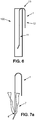
- said hole 4 can also receive a piece of fabric 7 for cleaning, for example a wipe, said piece of fabric 7 extending through said hole 4, the cutting tool 1 can then be used in the manner of a rod which is made to slide in a back and forth movement inside a tubular pipe 6, said piece of fabric 7 coming rub against the interior wall 61 of the pipe 6 to ensure its cleaning, as can be seen in the embodiment of the figure 7b .
- an end portion PE1 of the first section 11 situated at the level of the first free end E1 is inclined relative to the rest of the first section 11 by an angle ⁇ of between 5 ° and 60 °, preferably between 30 ° and 45 °, extending opposite to the second section 12.
- the scraping of the inner wall 61 of a tubular pipe 6, with the first end E1 of the cutting tool 1 according to the invention is easier, and in particular with respect to embodiments in which said end portion PE1 is located in the extension of the rest of the first section 11, the angle ⁇ being substantially equal to 0 °.
- a hook 5 is formed on an end portion PE2 of the second section 12 located at the second free end E2.
- Such a hook 5 can advantageously be used to scrape the walls of a tubular pipe 6.
- Such a hook 5 can be produced in the form of a cut in the metal strip.
- such a hook 5 does not have any pointed part, and in particular its point 51 is of rounded shape with a radius of curvature such that it does not risk injuring a user of the cutting tool 1.
- an intermediate portion (not shown) can be provided between said end portion PE2 and the rest of the second section 12.
- the end portion PE2 can be provided parallel to the rest of the second section 12, while said intermediate portion is inclined relative to the end portion PE2 and to the rest of the second section, for example by an angle between 5 ° and 60 °.
- Said end portion PE2 can then be positioned closer to the first section 11 than to the rest of the second section 12, or alternatively further from the first section 11 than to the rest of the second section 12.
- said end portion PE2 can constitute a bearing portion of the cutting tool 1 when positioned on a flat surface, in order to provide it with stability.
- said strip is a metal strip, produced in one piece in the form of a cut and folded sheet.
- the multifunction cutting tool 1 according to the invention is simple and inexpensive to produce.
- the third section 13, the first end portion PE1, the second end portion PE2, or even the intermediate portion between said end portion PE2 and the rest of the second section 12 can be obtained by folding.
- the rounded shape of the first end E1 or of the second end E2 can be obtained by cutting.
- said metal strip is made of stainless steel.
- stainless steel may possibly be a surgical type steel, which are stainless steels used in a good manner known in the manufacture of medical devices, or of elements requiring a high level of hygiene in order not to present a risk to the health of the user.
- the surgical type stainless steel used may for example be AISI 301.
- said strip can be made of any other suitable material, such as, for example, composite material.
- Said tubular pipe 6 can for example be made of glass.
- such a pipe 6 may comprise a single cylindrical portion.
- said pipe 6 may include two cylindrical portions connected together by a bent portion.
- a support and smoke filtration means can be positioned inside said pipe 6 in order to receive and maintain a pebble of solid or semi-solid product during its combustion inside pipe 6 for its consumption via the pipe 6.
- said pipe 6 and said multifunction cutting tool 1 are configured so that the pipe 6 can be received and held in position by the cutting tool enclosing the outer peripheral wall 62 of the pipe 6 between the first 11 and the second section 12 of the metal strip at the third angled section 13 of the metal strip.
- the cutting tool 1 can be used as a holding element in position of said pipe 6 when positioned on a flat surface S, and in particular in the case where said cutting tool 1 has an intermediate portion inclined between the portion PE2 end and the rest of the second section 12, as described above, which facilitates its use by a user.
- said pipe 6 and said multifunctional cutting tool 1 are configured so that the multifunctional cutting tool 1 can be received and held inside the pipe 6 when in said second configuration, the first section 11 and the second section 12 of the metal strip of the multifunction cutting tool 1 pressing against the inner peripheral wall 61 of the pipe 6.
- this advantageous arrangement of the invention makes it possible to reduce the size of the kit 100 according to the invention and to facilitate its transport and its storage for a user.
- said kit 100 further comprises a piece 7 of cleaning cloth, configured to be inserted and held in said hole 4 of the multifunction cutting tool 1 so as to allow the cleaning of the wall inner device 61 of the pipe 6.
- said piece of cleaning cloth 7 can extend and be held through said oblong hole 4 of the cutting tool 1, the cutting tool 1 can then be used in the manner a rod which is made to slide in a back and forth movement inside said pipe 6, said piece of fabric 7 coming to rub against the internal wall 61 of pipe 6 to ensure its cleaning, as visible on the example of the figure 7b .
- Said piece of fabric 7 can for example be a wipe soaked in cleaning product.
Landscapes
- Food-Manufacturing Devices (AREA)
Applications Claiming Priority (1)
| Application Number | Priority Date | Filing Date | Title |
|---|---|---|---|
| FR1872423A FR3089394A1 (fr) | 2018-12-06 | 2018-12-06 | Outil de coupe multifonction de sécurité et kit de consommation comprenant un tel outil de coupe multifonction |
Publications (1)
| Publication Number | Publication Date |
|---|---|
| EP3662768A1 true EP3662768A1 (de) | 2020-06-10 |
Family
ID=66049321
Family Applications (1)
| Application Number | Title | Priority Date | Filing Date |
|---|---|---|---|
| EP19213479.9A Withdrawn EP3662768A1 (de) | 2018-12-06 | 2019-12-04 | Multifunktionales sicherheits-schneidwerkzeug und verbrauchskit damit |
Country Status (3)
| Country | Link |
|---|---|
| EP (1) | EP3662768A1 (de) |
| CA (1) | CA3064245A1 (de) |
| FR (1) | FR3089394A1 (de) |
Citations (7)
| Publication number | Priority date | Publication date | Assignee | Title |
|---|---|---|---|---|
| GB191500108A (en) * | 1915-01-04 | 1915-12-30 | Percy Albert Craven | Improved Appliance for Cleaning Out Tobacco Pipe Bowls and the like. |
| US1227601A (en) * | 1912-10-28 | 1917-05-29 | Benjamin F Flegel | Pipe-bowl cleaner. |
| US1287681A (en) * | 1916-02-05 | 1918-12-17 | J L Sommer Mfg Co | Cleaner for pipes and the like. |
| GB141308A (en) * | 1920-02-03 | 1920-04-15 | Arthur Charles Keeping | An improved tobacco-pipe scraper |
| US1477207A (en) * | 1921-05-21 | 1923-12-11 | Frederick S Brown | Pipe cleaner |
| US2252989A (en) * | 1938-11-26 | 1941-08-19 | Thaddeus A Sikorski | Tobacco pipe reamer |
| FR3002724A1 (fr) | 2013-03-04 | 2014-09-05 | Terpan | Kit pour la consommation par inhalation |
-
2018
- 2018-12-06 FR FR1872423A patent/FR3089394A1/fr not_active Withdrawn
-
2019
- 2019-12-04 EP EP19213479.9A patent/EP3662768A1/de not_active Withdrawn
- 2019-12-06 CA CA3064245A patent/CA3064245A1/fr not_active Abandoned
Patent Citations (7)
| Publication number | Priority date | Publication date | Assignee | Title |
|---|---|---|---|---|
| US1227601A (en) * | 1912-10-28 | 1917-05-29 | Benjamin F Flegel | Pipe-bowl cleaner. |
| GB191500108A (en) * | 1915-01-04 | 1915-12-30 | Percy Albert Craven | Improved Appliance for Cleaning Out Tobacco Pipe Bowls and the like. |
| US1287681A (en) * | 1916-02-05 | 1918-12-17 | J L Sommer Mfg Co | Cleaner for pipes and the like. |
| GB141308A (en) * | 1920-02-03 | 1920-04-15 | Arthur Charles Keeping | An improved tobacco-pipe scraper |
| US1477207A (en) * | 1921-05-21 | 1923-12-11 | Frederick S Brown | Pipe cleaner |
| US2252989A (en) * | 1938-11-26 | 1941-08-19 | Thaddeus A Sikorski | Tobacco pipe reamer |
| FR3002724A1 (fr) | 2013-03-04 | 2014-09-05 | Terpan | Kit pour la consommation par inhalation |
Also Published As
| Publication number | Publication date |
|---|---|
| FR3089394A1 (fr) | 2020-06-12 |
| CA3064245A1 (fr) | 2020-06-06 |
Similar Documents
| Publication | Publication Date | Title |
|---|---|---|
| EP2012614B1 (de) | Anwendungsinstrument mit vereinfachter konstruktion und zugeordnetes herstellungsverfahren | |
| EP3420844B1 (de) | Applikatortrichter für kosmetikprodukt, entsprechender applikator und entsprechende applikatoranordnung | |
| EP1157629B1 (de) | Vorrichtung zum Auftragen eines kosmetischen oder pflegenden Produktes auf keratinische Faser, insbesondere auf Wimpern oder Augenbrauen | |
| EP0973466B1 (de) | Gehörgangreiniger | |
| EP1767119A1 (de) | Applikator zum Auftragen eines Produktes auf die Wimpern | |
| WO2016004541A1 (fr) | Instrument endodontique pour l'alesage de canaux radiculaires | |
| EP0425357A2 (de) | Zahnreinigungsgerät | |
| WO2007042635A1 (fr) | Pied de mixage et mixeur menager de type plongeant muni d'un tel pied de mixage | |
| FR2512677A1 (fr) | Aiguille chirurgicale creuse a usage unique, de preference du type redon | |
| FR3012303A1 (fr) | Applicateur pour produit cosmetique et ensemble applicateur associe | |
| EP3662768A1 (de) | Multifunktionales sicherheits-schneidwerkzeug und verbrauchskit damit | |
| EP3132709B1 (de) | Applikator für kosmetikprodukt, und entsprechende applikatoranordnung | |
| FR2969480A1 (fr) | Insert de detartrage | |
| EP2461719B1 (de) | Bürste zur reinigung eines containers | |
| WO2009156682A2 (fr) | Dispositif d'application d'un produit de traitement sur une surface à traiter, utilisation d'un tel dispositif pour le traitement d'un ongle de pied ou de la main et kit de traitement correspondant | |
| FR2859356A1 (fr) | Dispositif de scarification notamment pour produits de boulangerie | |
| WO2011073182A1 (fr) | Curette dermatologique | |
| EP3110288A1 (de) | Applikator für ein kosmetikprodukt und zugehörige applikatoranordnung | |
| BE471059A (fr) | Récipient pour peinture ou analogue | |
| FR2837696A1 (fr) | Dispositif de chirurgie ophtalmique | |
| EP2197335A1 (de) | Saug-abstandsspiegel für die odontologie und mund- und zahnpflege | |
| EP1053727A1 (de) | Handreinigungsinstrument und Verfahren zu dessen Herstellung | |
| CH720206A1 (fr) | Nettoyeur d'oreille | |
| BE1013270A3 (fr) | Rasoir pour coiffeur. | |
| FR2892899A1 (fr) | Lame gouge pour outil de podologie |
Legal Events
| Date | Code | Title | Description |
|---|---|---|---|
| PUAI | Public reference made under article 153(3) epc to a published international application that has entered the european phase |
Free format text: ORIGINAL CODE: 0009012 |
|
| STAA | Information on the status of an ep patent application or granted ep patent |
Free format text: STATUS: THE APPLICATION HAS BEEN PUBLISHED |
|
| AK | Designated contracting states |
Kind code of ref document: A1 Designated state(s): AL AT BE BG CH CY CZ DE DK EE ES FI FR GB GR HR HU IE IS IT LI LT LU LV MC MK MT NL NO PL PT RO RS SE SI SK SM TR |
|
| AX | Request for extension of the european patent |
Extension state: BA ME |
|
| STAA | Information on the status of an ep patent application or granted ep patent |
Free format text: STATUS: REQUEST FOR EXAMINATION WAS MADE |
|
| 17P | Request for examination filed |
Effective date: 20201208 |
|
| RBV | Designated contracting states (corrected) |
Designated state(s): AL AT BE BG CH CY CZ DE DK EE ES FI FR GB GR HR HU IE IS IT LI LT LU LV MC MK MT NL NO PL PT RO RS SE SI SK SM TR |
|
| GRAP | Despatch of communication of intention to grant a patent |
Free format text: ORIGINAL CODE: EPIDOSNIGR1 |
|
| STAA | Information on the status of an ep patent application or granted ep patent |
Free format text: STATUS: GRANT OF PATENT IS INTENDED |
|
| INTG | Intention to grant announced |
Effective date: 20210922 |
|
| GRAS | Grant fee paid |
Free format text: ORIGINAL CODE: EPIDOSNIGR3 |
|
| STAA | Information on the status of an ep patent application or granted ep patent |
Free format text: STATUS: THE APPLICATION IS DEEMED TO BE WITHDRAWN |
|
| 18D | Application deemed to be withdrawn |
Effective date: 20220701 |