EP3663005A1 - Mécanisme d'application de revêtement et dispositif d'application de revêtement - Google Patents
Mécanisme d'application de revêtement et dispositif d'application de revêtement Download PDFInfo
- Publication number
- EP3663005A1 EP3663005A1 EP18841077.3A EP18841077A EP3663005A1 EP 3663005 A1 EP3663005 A1 EP 3663005A1 EP 18841077 A EP18841077 A EP 18841077A EP 3663005 A1 EP3663005 A1 EP 3663005A1
- Authority
- EP
- European Patent Office
- Prior art keywords
- application
- application needle
- fixing member
- tip
- substrate
- Prior art date
- Legal status (The legal status is an assumption and is not a legal conclusion. Google has not performed a legal analysis and makes no representation as to the accuracy of the status listed.)
- Pending
Links
- 230000007246 mechanism Effects 0.000 title claims abstract description 123
- 239000011248 coating agent Substances 0.000 title 2
- 238000000576 coating method Methods 0.000 title 2
- 239000000758 substrate Substances 0.000 claims abstract description 74
- 239000000463 material Substances 0.000 claims abstract description 23
- 230000008859 change Effects 0.000 claims abstract description 9
- 238000000926 separation method Methods 0.000 claims abstract description 6
- 230000003287 optical effect Effects 0.000 description 8
- 230000008878 coupling Effects 0.000 description 6
- 238000010168 coupling process Methods 0.000 description 6
- 238000005859 coupling reaction Methods 0.000 description 6
- 238000010586 diagram Methods 0.000 description 6
- 230000000694 effects Effects 0.000 description 4
- 230000015572 biosynthetic process Effects 0.000 description 3
- 230000004048 modification Effects 0.000 description 3
- 238000012986 modification Methods 0.000 description 3
- 238000013459 approach Methods 0.000 description 2
- 229920000139 polyethylene terephthalate Polymers 0.000 description 2
- 239000005020 polyethylene terephthalate Substances 0.000 description 2
- 238000007796 conventional method Methods 0.000 description 1
- 230000006872 improvement Effects 0.000 description 1
- 239000000696 magnetic material Substances 0.000 description 1
- 239000002245 particle Substances 0.000 description 1
- -1 polyethylene terephthalate Polymers 0.000 description 1
- 238000012545 processing Methods 0.000 description 1
- 230000001629 suppression Effects 0.000 description 1
Images


Classifications
-
- B—PERFORMING OPERATIONS; TRANSPORTING
- B05—SPRAYING OR ATOMISING IN GENERAL; APPLYING FLUENT MATERIALS TO SURFACES, IN GENERAL
- B05C—APPARATUS FOR APPLYING FLUENT MATERIALS TO SURFACES, IN GENERAL
- B05C13/00—Means for manipulating or holding work, e.g. for separate articles
-
- B—PERFORMING OPERATIONS; TRANSPORTING
- B05—SPRAYING OR ATOMISING IN GENERAL; APPLYING FLUENT MATERIALS TO SURFACES, IN GENERAL
- B05C—APPARATUS FOR APPLYING FLUENT MATERIALS TO SURFACES, IN GENERAL
- B05C11/00—Component parts, details or accessories not specifically provided for in groups B05C1/00 - B05C9/00
- B05C11/10—Storage, supply or control of liquid or other fluent material; Recovery of excess liquid or other fluent material
- B05C11/1002—Means for controlling supply, i.e. flow or pressure, of liquid or other fluent material to the applying apparatus, e.g. valves
- B05C11/1034—Means for controlling supply, i.e. flow or pressure, of liquid or other fluent material to the applying apparatus, e.g. valves specially designed for conducting intermittent application of small quantities, e.g. drops, of coating material
-
- B—PERFORMING OPERATIONS; TRANSPORTING
- B05—SPRAYING OR ATOMISING IN GENERAL; APPLYING FLUENT MATERIALS TO SURFACES, IN GENERAL
- B05C—APPARATUS FOR APPLYING FLUENT MATERIALS TO SURFACES, IN GENERAL
- B05C1/00—Apparatus in which liquid or other fluent material is applied to the surface of the work by contact with a member carrying the liquid or other fluent material, e.g. a porous member loaded with a liquid to be applied as a coating
- B05C1/02—Apparatus in which liquid or other fluent material is applied to the surface of the work by contact with a member carrying the liquid or other fluent material, e.g. a porous member loaded with a liquid to be applied as a coating for applying liquid or other fluent material to separate articles
-
- B—PERFORMING OPERATIONS; TRANSPORTING
- B05—SPRAYING OR ATOMISING IN GENERAL; APPLYING FLUENT MATERIALS TO SURFACES, IN GENERAL
- B05C—APPARATUS FOR APPLYING FLUENT MATERIALS TO SURFACES, IN GENERAL
- B05C5/00—Apparatus in which liquid or other fluent material is projected, poured or allowed to flow on to the surface of the work
- B05C5/02—Apparatus in which liquid or other fluent material is projected, poured or allowed to flow on to the surface of the work the liquid or other fluent material being discharged through an outlet orifice by pressure, e.g. from an outlet device in contact or almost in contact, with the work
-
- B—PERFORMING OPERATIONS; TRANSPORTING
- B05—SPRAYING OR ATOMISING IN GENERAL; APPLYING FLUENT MATERIALS TO SURFACES, IN GENERAL
- B05C—APPARATUS FOR APPLYING FLUENT MATERIALS TO SURFACES, IN GENERAL
- B05C5/00—Apparatus in which liquid or other fluent material is projected, poured or allowed to flow on to the surface of the work
- B05C5/02—Apparatus in which liquid or other fluent material is projected, poured or allowed to flow on to the surface of the work the liquid or other fluent material being discharged through an outlet orifice by pressure, e.g. from an outlet device in contact or almost in contact, with the work
- B05C5/0225—Apparatus in which liquid or other fluent material is projected, poured or allowed to flow on to the surface of the work the liquid or other fluent material being discharged through an outlet orifice by pressure, e.g. from an outlet device in contact or almost in contact, with the work characterised by flow controlling means, e.g. valves, located proximate the outlet
-
- H—ELECTRICITY
- H05—ELECTRIC TECHNIQUES NOT OTHERWISE PROVIDED FOR
- H05K—PRINTED CIRCUITS; CASINGS OR CONSTRUCTIONAL DETAILS OF ELECTRIC APPARATUS; MANUFACTURE OF ASSEMBLAGES OF ELECTRICAL COMPONENTS
- H05K3/00—Apparatus or processes for manufacturing printed circuits
- H05K3/10—Apparatus or processes for manufacturing printed circuits in which conductive material is applied to the insulating support in such a manner as to form the desired conductive pattern
- H05K3/12—Apparatus or processes for manufacturing printed circuits in which conductive material is applied to the insulating support in such a manner as to form the desired conductive pattern using thick film techniques, e.g. printing techniques to apply the conductive material or similar techniques for applying conductive paste or ink patterns
- H05K3/1241—Apparatus or processes for manufacturing printed circuits in which conductive material is applied to the insulating support in such a manner as to form the desired conductive pattern using thick film techniques, e.g. printing techniques to apply the conductive material or similar techniques for applying conductive paste or ink patterns by ink-jet printing or drawing by dispensing
-
- H—ELECTRICITY
- H05—ELECTRIC TECHNIQUES NOT OTHERWISE PROVIDED FOR
- H05K—PRINTED CIRCUITS; CASINGS OR CONSTRUCTIONAL DETAILS OF ELECTRIC APPARATUS; MANUFACTURE OF ASSEMBLAGES OF ELECTRICAL COMPONENTS
- H05K2203/00—Indexing scheme relating to apparatus or processes for manufacturing printed circuits covered by H05K3/00
- H05K2203/01—Tools for processing; Objects used during processing
- H05K2203/0104—Tools for processing; Objects used during processing for patterning or coating
- H05K2203/0126—Dispenser, e.g. for solder paste, for supplying conductive paste for screen printing or for filling holes
Definitions
- the present invention relates to an application mechanism and an application apparatus. More particularly, the present invention relates to an application mechanism and an application apparatus each for applying an application material onto a substrate.
- the application mechanism disclosed in PTL 1 includes an application needle, an application-needle fixing plate, an arm, a linear guide member, a support stage, a cylinder, and a pin.
- the application needle is attached to the application-needle fixing plate.
- the application-needle fixing plate is attached to the arm.
- the linear guide member is attached to the support stage and supports the arm so as to be movable in the up-down direction.
- the cylinder is attached to the support stage and has a drive plate.
- the pin horizontally extends so as to support the arm and is attached to the drive plate.
- the cylinder moves the drive plate downward to thereby prevent the pin from supporting the arm.
- the arm moves downward due to its self-weight, so that the application needle comes into contact with the substrate.
- the application material is applied.
- the application mechanism disclosed in PTL 2 includes an application needle, an application needle holder, an arm, a slide mechanism, a support pin, a cylinder, a support member, and a contact-pressure reducing mechanism.
- the application needle is attached to the application needle holder.
- the application needle holder is attached to the arm.
- the slide mechanism is attached to the support member and supports the arm so as to be movable in the up-down direction.
- the pin horizontally extends so as to support the arm.
- the cylinder is attached to the support member and moves the pin in the up-down direction. When the pin is moved downward to thereby prevent the pin from supporting the arm.
- the arm and the application needle that is attached to the arm through the support needle holder move due to their self-weights toward the substrate.
- the contact-pressure reducing mechanism serves to couple the arm and the support member.
- the contact-pressure reducing mechanism is a spring, for example.
- the contact-pressure reducing mechanism applies force to the arm so as to be raised upward as the application needle approaches the substrate.
- the contact pressure exerted by the application needle upon the substrate is reduced.
- the application mechanism disclosed in PTL 3 includes an application needle and an application needle holder.
- the application needle holder includes a holder base, an application needle fixing member, a linear motion member, and an elastic member.
- the application needle is attached to the application needle fixing member.
- the linear motion member is attached to the holder base and supports the application needle fixing member so as to be movable in one direction.
- the elastic member couples the holder base and the application needle fixing member. The elastic member applies force to the application needle so as to be moved toward the substrate.
- the weights of the application needle, the application-needle fixing plate and the arm are exerted as self-weights on the application needle tip.
- the pressure between the application needle tip and the substrate may cause a dent in the substrate or damage to the application needle tip.
- the contact-pressure reducing mechanism reduces the pressure between the application needle tip and the substrate.
- the effect of reducing the pressure between the application needle tip and the substrate by the contact-pressure reducing mechanism is lessened in accordance with an increase in speed at which the application needle comes into contact with the substrate.
- the application mechanism disclosed in PTL 2 may also cause damage to the application needle tip or a dent in the substrate.
- the application mechanism disclosed in PTL 3 when the application needle tip comes into contact with the substrate, only the weights of the application needle and the application needle fixing member are exerted as self-weights.
- the pressure between the application needle tip and the substrate is relatively low, thereby suppressing a dent in the substrate and damage to the application needle tip.
- the elastic member applies force to the application needle so as to be moved toward the substrate.
- the force applied by the elastic member increases the pressure between the application needle tip and the substrate. Accordingly, the application mechanism disclosed in PTL 3 also has room for improvement in order to prevent damage to the application needle tip and a dent in the substrate.
- the present invention has been made in view of the above-described problems of the conventional techniques. More specifically, the present invention is to provide an application mechanism and an application apparatus, each of which allows suppression of damage to an application needle tip and a dent in a substrate.
- An application mechanism serves as an application mechanism that applies an application material onto a substrate using an application needle.
- the application mechanism includes: a holder base; a slide mechanism attached to an inside of the holder base; an application needle fixing member, to which the application needle is attached, the application needle fixing member being supported by the slide mechanism so as to be slidable in an extending direction of the application needle; and a position holding mechanism that holds a relative position of the application needle fixing member with respect to the slide mechanism.
- the position holding mechanism holds the relative position of the application needle fixing member with respect to the slide mechanism until immediately before contact of a tip of the application needle with the substrate.
- the position holding mechanism allows the relative position of the application needle fixing member with respect to the slide mechanism to change from immediately before contact of the tip of the application needle with the substrate until separation of the tip of the application needle from the substrate.
- the position holding mechanism may be constituted of a magnetic member and an electromagnet that is disposed to face the magnetic member.
- the magnetic member may be a permanent magnet.
- the magnetic member may be attached to the application needle fixing member, and the electromagnet may be attached to the holder base.
- An application apparatus includes the above-described application mechanism.
- An application mechanism and an application apparatus can suppress damage to an application needle tip and a dent in a substrate.
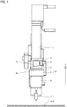
- Fig. 1 is a front view of application mechanism 10 according to an embodiment.
- application mechanism 10 includes a servo motor 1, a cam 2, a bearing 3, a cam coupling plate 4, a movable portion 5, an application needle holder 6, and an application material container 7.
- Application mechanism 10 serves as a mechanism for applying an application material onto a substrate SUB.
- substrate SUB include a polyethylene terephthalate (PET) film and the like.
- Servo motor 1 has a rotational shaft.
- the rotational shaft of servo motor 1 extends in the Z direction.
- the rotational shaft of servo motor 1 is rotatable about the central axis.
- Cam 2 is attached to the rotational shaft of servo motor 1.
- Cam 2 is rotatable about the central axis of the rotational shaft of servo motor 1.
- Cam 2 has a first surface 2a and a second surface 2b.
- Cam 2 is attached at first surface 2a to the rotational shaft of servo motor 1.
- Second surface 2b is on the side opposite to first surface 2a.
- Second surface 2b is orthogonal to the Z direction.
- Cam 2 has a center portion and a flange portion. Cam 2 is attached at first surface 2a located in the center portion to the rotational shaft of servo motor 1.
- the flange portion is disposed on the outer circumference of the center portion.
- First surface 2a located in the flange portion serves as a cam surface. In other words, the distance between first surface 2a that is located in the flange portion and second surface 2b varies along the circumferential direction of the flange portion.
- Bearing 3 is disposed such that its outer circumferential surface is in contact with the cam surface of cam 2 (first surface 2a located in the flange portion).
- Cam coupling plate 4 has one end and the other end. One end of cam coupling plate 4 is coupled to bearing 3. The other end is on the side opposite to this one end.
- Movable portion 5 is coupled to the other end of cam coupling plate 4.
- Application needle holder 6 is attached to movable portion 5.
- Fig. 2 is an internal structure diagram of application needle holder 6.
- application needle holder 6 includes a holder base 61, an application needle fixing member 62, an application needle 63, a slide mechanism 64, and a position holding mechanism 65.
- Application needle fixing member 62, slide mechanism 64, and position holding mechanism 65 are housed inside holder base 61.
- Application needle fixing member 62 has a first end 62a and a second end 62b. First end 62a and second end 62b are both ends of application needle fixing member 62 in its longitudinal direction. The longitudinal direction of application needle fixing member 62 extends in the Z direction.
- Application needle 63 is attached to application needle fixing member 62. Specifically, application needle 63 is attached such that its tip side protrudes from first end 62a of application needle fixing member 62. Application needle 63 extends in the Z direction.
- Slide mechanism 64 is attached to holder base 61.
- Application needle fixing member 62 is supported by slide mechanism 64 so as to be slidable in the extending direction of application needle 63 (in the Z direction).
- the state where application needle fixing member 62 is supported by slide mechanism 64 so as to be slidable means that there is no exertion of force restricting the sliding motion of application needle fixing member 62 with respect to slide mechanism 64 except for the sliding resistance between application needle fixing member 62 and slide mechanism 64.
- slide mechanism 64 a linear guide is used, for example.
- Position holding mechanism 65 is constituted of a magnetic member 65a and an electromagnet 65b, for example.
- Magnetic member 65a is attached to application needle fixing member 62. More specifically, magnetic member 65a is attached to second end 62b of application needle fixing member 62. Magnetic member 65a is made using a magnetic material. Magnetic member 65a may be a permanent magnet. Magnetic member 65a extends in the direction crossing the Z direction. Electromagnet 65b is attached to holder base 61.
- Electromagnet 65b is disposed so as to face magnetic member 65a. Electromagnet 65b is configured to generate attraction force for magnetic member 65a by current conduction through electromagnet 65b. As will be described later, current conduction through electromagnet 65b is performed between time t A and time t B in Fig. 4 , and performed between time tc and time t D in Fig. 4 , but not performed between time t B and time tc in Fig. 4 .
- position holding mechanism 65 holds the relative position of application needle fixing member 62 with respect to slide mechanism 64 until immediately before contact of the tip of application needle 63 with substrate SUB, but allows the relative position between application needle fixing member 62 and slide mechanism 64 to change from immediately before contact of the tip of application needle 63 with substrate SUB until separation of the tip of application needle 63 from substrate SUB.
- Fig. 3 is an internal structure diagram of a modification of application needle holder 6.
- magnetic member 65a is attached to second end 62b of application needle fixing member 62.
- Electromagnet 65b is attached to the inner wall surface of holder base 61 that faces second end 62b of application needle fixing member 62.
- Electromagnet 65b is configured to generate repulsive force for magnetic member 65a by current conduction through electromagnet 65b. Thereby, position holding mechanism 65 may hold the relative position of application needle fixing member 62 with respect to slide mechanism 64.
- application material container 7 is disposed closer to substrate SUB than application needle holder 6 in the Z direction.
- Application material container 7 is filled with an application material.
- the application material may be a material in a paste state containing electrical conductive particles.
- Application needle 63 extends through application material container 7 (the tip of application needle 63 protrudes from the bottom surface of application material container 7).
- the rotational shaft of servo motor 1 rotates about the central axis, to thereby cause cam 2 to rotate about the central axis of the rotational shaft of servo motor 1.
- the distance between the cam surface (first surface 2a located in the flange portion) and second surface 2b varies along the circumferential direction of the flange portion.
- rotation of cam 2 causes a change in position of bearing 3 in the Z direction that is in contact with the cam surface.
- Bearing 3 is coupled to movable portion 5 with cam coupling plate 4 interposed therebetween.
- Application needle holder 6 is attached to movable portion 5.
- a change in the position of bearing 3 in the Z direction causes a change in the position of application needle holder 6 in the Z direction.
- Fig. 4 is a graph showing a profile of a tip position of application needle 63.
- the horizontal axis shows time while the vertical axis shows a moving speed of the tip of application needle 63.
- the tip of application needle 63 is located at the upper end position at time t A . From time t A to time t B , by current conduction through electromagnet 65b, the relative position of application needle fixing member 62 with respect to slide mechanism 64 is fixed.
- application needle holder 6 (holder base 61) is moved closer to substrate SUB, so that the position of the tip of application needle 63 in the Z direction approaches substrate SUB (the tip of application needle 63 follows the movement of holder base 61).
- the tip of application needle 63 is in the state immediately before it comes into contact with substrate SUB.
- the distance between the tip of application needle 63 and substrate SUB at time t B (that is, the distance between the tip of application needle 63 and substrate SUB immediately before contact of the tip of application needle 63 with substrate SUB) is set in advance. It should be noted that the position of the tip of application needle 63 can be controlled as a rotation angle of servo motor 1.
- position holding mechanism 65 holds the relative position of application needle fixing member 62 with respect to slide mechanism 64 since a current conducts through electromagnet 65b from time t A to time t B in Fig. 4 (until immediately before contact of the tip of application needle 63 with substrate SUB) and from time tc to time t D (after separation of the tip of application needle 63 from substrate SUB).
- position holding mechanism 65 allows the relative position between application needle fixing member 62 and slide mechanism 64 to change since no current conducts through electromagnet 65b from time t B to time tc in Fig. 4 (from immediately before contact of the tip of application needle 63 with substrate SUB until separation of the tip of application needle 63 from substrate SUB).
- application mechanism 10 can suppress an increase in contact load between application needle 63 and substrate SUB, so that damage to the tip of application needle 63 and a dent in the substrate can be suppressed.
- the tip of application needle 63 receiving a load exceeding its self-weight may cause damage to substrate SUB, such as peeling off of the application material applied onto substrate SUB from substrate SUB.
- the relative position between application needle fixing member 62 and slide mechanism 64 is allowed to change while the tip of application needle 63 is in contact with substrate SUB, as described above. This prevents the tip of application needle 63 from receiving a load exceeding its self-weight.
- damage to substrate SUB can be suppressed, for examples, even in the case where application needle 63 having a tip diameter of 10 ⁇ m or less is used.
- Fig. 5 is a schematic diagram of application apparatus 100.
- application apparatus 100 includes an application mechanism 10, an X-axis table 20, a Y-axis table 21, a Z-axis table 30, an observation optical system 40, a CCD camera 50, a control computer 60, a monitor 70, and an operation panel 80.
- Substrate SUB is mounted on X-axis table 20 and Y-axis table 21.
- X-axis table 20 and Y-axis table 21 can move substrate SUB in the X-axis direction and the Y direction, respectively.
- Application mechanism 10 is attached to Z-axis table 30 and movable in the Z direction.
- Observation optical system 40 is used to observe an application position on substrate SUB.
- CCD camera 50 converts the image on substrate SUB observed by observation optical system 40 into an electrical signal.
- Control computer 60 controls application mechanism 10, X-axis table 20, Y-axis table 21, Z-axis table 30, observation optical system 40, and CCD camera 50.
- Monitor 70 displays the image signal obtained by CCD camera 50 and the image from control computer 60.
- Operation panel 80 is configured such that a command to the control computer can be input therethrough.
- X-axis table 20 and Y-axis table 21 are driven to move a region, on which a circuit pattern is to be formed, to directly below observation optical system 40. Thereby, the position at which formation of a circuit pattern is started (hereinafter referred to as a starting position) is checked and determined.
- application mechanism 10 applies an application material onto substrate SUB to thereby form a circuit pattern.
- X-axis table 20 and Y-axis table 21 are driven to move substrate SUB such that the position onto which an application material is applied (hereinafter referred to as an application position) is located directly below application mechanism 10.
- an application material is applied onto the application position by application mechanism 10.
- X-axis table 20 and Y-axis table 21 are driven to move substrate SUB such that the next application position is located directly below the application mechanism.
- the relation between the lowermost end position of application needle 63 to which application needle 63 is lowered and the focus position of observation optical system 40 is stored in advance.
- the position where the image of observation optical system 40 is focused is used as a reference in the Z-axis direction, and application mechanism 10 is moved by Z-axis table 30 to the position where application needle 63 comes into contact with substrate SUB before the application material is applied as described above.
- the application material is applied while checking the focus position to correct the position of application mechanism 10 in the Z direction during this formation.
- This checking and adjustment of the focus position may be performed automatically by using image processing, or may be performed in real time while detecting the position of the surface of substrate SUB in the Z direction by a laser sensor and the like.
Landscapes
- Engineering & Computer Science (AREA)
- Manufacturing & Machinery (AREA)
- Microelectronics & Electronic Packaging (AREA)
- Coating Apparatus (AREA)
Applications Claiming Priority (2)
| Application Number | Priority Date | Filing Date | Title |
|---|---|---|---|
| JP2017149884A JP6461260B1 (ja) | 2017-08-02 | 2017-08-02 | 塗布機構及び塗布装置 |
| PCT/JP2018/026914 WO2019026624A1 (fr) | 2017-08-02 | 2018-07-18 | Mécanisme d'application de revêtement et dispositif d'application de revêtement |
Publications (2)
| Publication Number | Publication Date |
|---|---|
| EP3663005A1 true EP3663005A1 (fr) | 2020-06-10 |
| EP3663005A4 EP3663005A4 (fr) | 2021-04-21 |
Family
ID=65229021
Family Applications (1)
| Application Number | Title | Priority Date | Filing Date |
|---|---|---|---|
| EP18841077.3A Pending EP3663005A4 (fr) | 2017-08-02 | 2018-07-18 | Mécanisme d'application de revêtement et dispositif d'application de revêtement |
Country Status (5)
| Country | Link |
|---|---|
| US (1) | US11511311B2 (fr) |
| EP (1) | EP3663005A4 (fr) |
| JP (1) | JP6461260B1 (fr) |
| CN (1) | CN110997157A (fr) |
| WO (1) | WO2019026624A1 (fr) |
Families Citing this family (3)
| Publication number | Priority date | Publication date | Assignee | Title |
|---|---|---|---|---|
| CN112718387A (zh) * | 2020-12-23 | 2021-04-30 | 昂纳信息技术(深圳)有限公司 | 一种点胶装置 |
| JP7621134B2 (ja) * | 2021-02-25 | 2025-01-24 | Ntn株式会社 | 塗布機構及び塗布装置 |
| CN113510045A (zh) * | 2021-05-10 | 2021-10-19 | 江苏玺泽祥智能科技有限公司 | Ro膜自动卷膜机的自动灌胶机构 |
Family Cites Families (13)
| Publication number | Priority date | Publication date | Assignee | Title |
|---|---|---|---|---|
| US5186982A (en) * | 1990-09-18 | 1993-02-16 | Minnesota Mining And Manufacturing Company | Pin transfer applicator and method |
| US6915928B2 (en) * | 2001-01-29 | 2005-07-12 | Pemstar, Inc. | Fluid dispenser |
| JP4767567B2 (ja) * | 2005-03-28 | 2011-09-07 | Ntn株式会社 | パターン修正装置 |
| JP4767708B2 (ja) * | 2005-03-28 | 2011-09-07 | Ntn株式会社 | 塗布ユニットおよびパターン修正装置 |
| JP4802027B2 (ja) | 2006-03-30 | 2011-10-26 | Ntn株式会社 | パターン修正装置およびその塗布ユニット |
| JP4928284B2 (ja) * | 2007-01-23 | 2012-05-09 | 芝浦メカトロニクス株式会社 | 流体塗布装置および塗布距離測定方法 |
| JP2008296148A (ja) * | 2007-05-31 | 2008-12-11 | Ntn Corp | 液状材料塗布機構およびそれを用いた欠陥修正装置 |
| JP5969281B2 (ja) * | 2011-10-24 | 2016-08-17 | Ntn株式会社 | 液状材料塗布装置およびそれを含む欠陥修正装置 |
| JP6189102B2 (ja) * | 2013-06-25 | 2017-08-30 | Ntn株式会社 | 塗布装置および高さ検出方法 |
| US9153305B2 (en) | 2013-08-30 | 2015-10-06 | Micron Technology, Inc. | Independently addressable memory array address spaces |
| JP6411735B2 (ja) * | 2013-12-13 | 2018-10-24 | Ntn株式会社 | 塗布部材、塗布装置および塗布方法 |
| JP6381902B2 (ja) * | 2013-12-13 | 2018-08-29 | Ntn株式会社 | 塗布針ホルダ |
| JP6749814B2 (ja) * | 2015-11-12 | 2020-09-02 | Ntn株式会社 | 高さ検出装置およびそれを搭載した塗布装置 |
-
2017
- 2017-08-02 JP JP2017149884A patent/JP6461260B1/ja active Active
-
2018
- 2018-07-18 WO PCT/JP2018/026914 patent/WO2019026624A1/fr not_active Ceased
- 2018-07-18 EP EP18841077.3A patent/EP3663005A4/fr active Pending
- 2018-07-18 US US16/635,519 patent/US11511311B2/en active Active
- 2018-07-18 CN CN201880049958.6A patent/CN110997157A/zh active Pending
Also Published As
| Publication number | Publication date |
|---|---|
| CN110997157A (zh) | 2020-04-10 |
| US20200254477A1 (en) | 2020-08-13 |
| US11511311B2 (en) | 2022-11-29 |
| WO2019026624A1 (fr) | 2019-02-07 |
| JP6461260B1 (ja) | 2019-01-30 |
| JP2019025450A (ja) | 2019-02-21 |
| EP3663005A4 (fr) | 2021-04-21 |
Similar Documents
| Publication | Publication Date | Title |
|---|---|---|
| US11511311B2 (en) | Application mechanism and application apparatus | |
| JP6411735B2 (ja) | 塗布部材、塗布装置および塗布方法 | |
| EP3507973B1 (fr) | Appareil d'imagerie avec capteur d'image mobile | |
| EP3381569B1 (fr) | Unité de revêtement, dispositif de revêtement, procédé de production d'un objet à revêtir et procédé de production d'un substrat | |
| TWI690371B (zh) | 液體塗佈單元及液體塗佈裝置 | |
| TW200839221A (en) | Vision inspection system and method for inspecting workpiece using the same | |
| JP6514047B2 (ja) | 塗布ユニットおよびそれを用いた塗布装置 | |
| JP6381902B2 (ja) | 塗布針ホルダ | |
| EP3062333B1 (fr) | Dispositif de liaison à température normale | |
| JP6491296B2 (ja) | 塗布部材、塗布装置および塗布方法 | |
| JP6560108B2 (ja) | 塗布ユニット、塗布装置、被塗布対象物の製造方法および基板の製造方法 | |
| JP6745683B2 (ja) | 液体塗布ユニット、液体塗布装置および液体塗布方法 | |
| EP3409375B1 (fr) | MÉCANISME D'APPLICATION ET PROCÉDÉ DE FABRICATION D'UN OBJET SUR
LEQUEL UN MATÉRIAU EST APPLIQUÉ | |
| JP2018130694A (ja) | 液体塗布ユニットおよび液体塗布装置 | |
| JP6716654B2 (ja) | 塗布部材、塗布装置および塗布方法 | |
| JP2017094287A (ja) | 塗布ユニット、塗布装置、被塗布対象物の製造方法および基板の製造方法 | |
| JP2006250636A (ja) | 移動装置 | |
| JPH07198729A (ja) | プローブ顕微鏡装置の探針接近方法 | |
| JP2000277561A (ja) | 可動ステージ装置 | |
| WO2016204152A1 (fr) | Dispositif de revêtement |
Legal Events
| Date | Code | Title | Description |
|---|---|---|---|
| STAA | Information on the status of an ep patent application or granted ep patent |
Free format text: STATUS: THE INTERNATIONAL PUBLICATION HAS BEEN MADE |
|
| PUAI | Public reference made under article 153(3) epc to a published international application that has entered the european phase |
Free format text: ORIGINAL CODE: 0009012 |
|
| STAA | Information on the status of an ep patent application or granted ep patent |
Free format text: STATUS: REQUEST FOR EXAMINATION WAS MADE |
|
| 17P | Request for examination filed |
Effective date: 20200218 |
|
| AK | Designated contracting states |
Kind code of ref document: A1 Designated state(s): AL AT BE BG CH CY CZ DE DK EE ES FI FR GB GR HR HU IE IS IT LI LT LU LV MC MK MT NL NO PL PT RO RS SE SI SK SM TR |
|
| AX | Request for extension of the european patent |
Extension state: BA ME |
|
| DAV | Request for validation of the european patent (deleted) | ||
| DAX | Request for extension of the european patent (deleted) | ||
| A4 | Supplementary search report drawn up and despatched |
Effective date: 20210323 |
|
| RIC1 | Information provided on ipc code assigned before grant |
Ipc: B05C 1/02 20060101AFI20210317BHEP Ipc: B05C 11/10 20060101ALI20210317BHEP Ipc: H05K 3/00 20060101ALI20210317BHEP |
|
| STAA | Information on the status of an ep patent application or granted ep patent |
Free format text: STATUS: EXAMINATION IS IN PROGRESS |
|
| 17Q | First examination report despatched |
Effective date: 20230531 |