EP3663445B1 - Buse de filage ainsi que procédé de nettoyage d'une telle buse de filage - Google Patents
Buse de filage ainsi que procédé de nettoyage d'une telle buse de filage Download PDFInfo
- Publication number
- EP3663445B1 EP3663445B1 EP19213386.6A EP19213386A EP3663445B1 EP 3663445 B1 EP3663445 B1 EP 3663445B1 EP 19213386 A EP19213386 A EP 19213386A EP 3663445 B1 EP3663445 B1 EP 3663445B1
- Authority
- EP
- European Patent Office
- Prior art keywords
- spinning nozzle
- yarn
- forming element
- spinneret
- spinning
- Prior art date
- Legal status (The legal status is an assumption and is not a legal conclusion. Google has not performed a legal analysis and makes no representation as to the accuracy of the status listed.)
- Active
Links
Images
Classifications
-
- D—TEXTILES; PAPER
- D01—NATURAL OR MAN-MADE THREADS OR FIBRES; SPINNING
- D01H—SPINNING OR TWISTING
- D01H4/00—Open-end spinning machines or arrangements for imparting twist to independently moving fibres separated from slivers; Piecing arrangements therefor; Covering endless core threads with fibres by open-end spinning techniques
- D01H4/02—Open-end spinning machines or arrangements for imparting twist to independently moving fibres separated from slivers; Piecing arrangements therefor; Covering endless core threads with fibres by open-end spinning techniques imparting twist by a fluid, e.g. air vortex
-
- D—TEXTILES; PAPER
- D01—NATURAL OR MAN-MADE THREADS OR FIBRES; SPINNING
- D01H—SPINNING OR TWISTING
- D01H1/00—Spinning or twisting machines in which the product is wound-up continuously
- D01H1/11—Spinning by false-twisting
- D01H1/115—Spinning by false-twisting using pneumatic means
-
- D—TEXTILES; PAPER
- D01—NATURAL OR MAN-MADE THREADS OR FIBRES; SPINNING
- D01H—SPINNING OR TWISTING
- D01H4/00—Open-end spinning machines or arrangements for imparting twist to independently moving fibres separated from slivers; Piecing arrangements therefor; Covering endless core threads with fibres by open-end spinning techniques
- D01H4/04—Open-end spinning machines or arrangements for imparting twist to independently moving fibres separated from slivers; Piecing arrangements therefor; Covering endless core threads with fibres by open-end spinning techniques imparting twist by contact of fibres with a running surface
- D01H4/22—Cleaning of running surfaces
Definitions
- the present invention relates to a spinneret for an air-jet spinning machine for producing a yarn from a fiber structure fed to the spinneret, the spinneret having an inner cavity in the form of an internal turbulence chamber which is at least partially outwardly delimited by a first spinneret section and a second spinneret section.
- the spinneret sections are, in particular, housing sections of the housing delimiting the spinneret to the outside.
- the first spinneret section comprises an inlet opening for the strand-shaped fiber structure and a number of air nozzles, via which air can be introduced into the turbulence chamber.
- the spinneret is connected to a corresponding compressed air line after the installation of an air spinning machine.
- the spinneret comprises a preferably spindle-shaped yarn-forming element that extends at least partially into the turbulence chamber and has an inlet for the fiber structure and an outlet for the yarn produced within the turbulence chamber in the region of the yarn-formation element during operation of the spinneret.
- the inlet and the outlet are connected to a discharge duct running inside the yarn-forming element.
- the yarn-forming element is held by the second spinneret section with the aid of a guide and can be moved between a spinning position and a cleaning position relative to the second spinneret section.
- a method for cleaning a spinneret on an air-jet spinning machine which is used to produce a yarn from a fiber structure fed to the spinneret, is proposed, the spinneret in turn having an internal turbulence chamber which is at least partially outwards from a first spinneret section and a second spinneret section is limited towards.
- the first Spinneret section has an inlet opening for the fiber structure and several air nozzles, via which air is introduced into the turbulence chamber during operation of the air nozzle.
- the spinneret has a yarn-forming element that extends at least partially into the turbulence chamber and has an inlet for the fiber structure and an outlet for the yarn produced within the turbulence chamber in the region of the yarn-forming element during operation of the spinneret.
- the method provides for the yarn-forming element to be moved from a spinning position into a cleaning position relative to the second spinneret section before or during the opening of the spinneret.
- Generic spinnerets are used to produce a yarn from an elongated fiber structure with the help of a turbulent air flow generated by appropriate air nozzles within the turbulence chamber.
- the outer fibers of the fiber structure are wound around the inner fibers (core fibers) in the area of the inlet of the generally spindle-shaped yarn-forming element, resulting in a yarn that is finally drawn off from the eddy chamber via the discharge channel of the yarn-forming element and with the help of a winding device can be wound onto a sleeve.
- Corresponding spinnerets are, for example, from JP 2001 131834 A or the DE 10 2008 050 874 A1 known.
- the spinneret housing surrounding the turbulence chamber in several parts.
- the individual spinneret sections are mounted so that they can move relative to one another, so that the housing can be opened by moving one or more spinneret sections. After opening, the interior of the spinneret is accessible and deposits (avivage, honeydew, etc.) can be removed.
- the object of the present invention is to improve a generic spinneret and to propose an improved method for opening or cleaning a spinneret.
- the yarn-forming element is held by the second spinneret section with the aid of a guide.
- the guide is preferably a component of the second spinneret section or is formed directly by it, for example with the aid of the bore, which will be explained in more detail later.
- the guide is designed in such a way that the yarn-forming element can be moved relative to the second spinneret section and thus also relative to the first spinneret section. In particular, a movement from a spinning position to a cleaning position is possible.
- the spinning position is that position which the yarn-forming element assumes during a spinning process, i.e. during the production of a yarn.
- the cleaning position is a position that the yarn-forming element assumes when the spinning process has been interrupted and cleaning of the yarn-forming element or the turbulence chamber is desired.
- the yarn-forming element is moved into the cleaning position in a direction away from the inlet opening of the spinneret.
- the distance between the inlet opening and the inlet of the yarn-forming element is greater than in the spinning position.
- the spinneret also includes a suction channel, which is preferably designed as an opening in a wall of the second spinneret section that delimits the vortex chamber to the outside.
- the suction channel is connected to a vacuum supply, so that air can be sucked out of the turbulence chamber via the suction channel and thus also in the turbulence chamber or on the yarn-forming element adhering impurities.
- air flows through the inlet opening of the spinneret into the vortex chamber.
- the movement of the yarn-forming element from the spinning position to the cleaning position favors the suctioning off of impurities in the form of fiber residues, which wrap around the tip of the yarn-forming element having the inlet and negatively influence the spinning process.
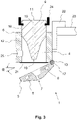
- the first spinneret section is attached to the second spinneret section via at least one pivot axis and can be pivoted about the pivot axis from a closed position into an open position.
- the closed position is the position of the first spinneret section, which it assumes during the spinning process. In this position, the first spinneret section is in contact with the second spinneret section, so that the vortex chamber is closed to the outside by the two spinneret sections.
- first spinneret section is pivoted from its closed position, it is in its open position.
- the open position is understood to mean any position of the first spinneret section which deviates from the closed position. Furthermore, it is provided that the inlet of the yarn-forming element is accessible to an operator from the outside only in the open position, regardless of the position of the yarn-forming element (spinning position or cleaning position). If the first spinneret section is in its closed position, the tip of the yarn-forming element is not accessible from the outside and is protected.
- the pivoting of the first spinneret section thus opens the spinneret as a whole, so that an operator from the outside can directly remove fiber residues from the tip of the yarn-forming element, which has the inlet. After this cleaning process, the first spinneret section can be pivoted back from its open position into the spinning position, so that the spinning process can be continued.
- the first spinneret section can preferably only be pivoted relative to the second spinneret section.
- the pivot axis is actively connected to the first spinneret section on the one hand and to the second spinneret section on the other hand.
- both the first spinneret section and the second spinneret section have a receptacle into which the pivot axis extends.
- the pivot axis does not necessarily have to be a bolt-shaped structure.
- the pivot axis can be merely an imaginary axis about which the first spinneret section can be pivoted relative to the second spinneret section.
- the two spinneret sections can be connected, for example, by a lug that enables the desired pivoting process.
- the yarn-forming element can be moved relative to the second spinneret section exclusively linearly and preferably collinearly to a longitudinal axis of a discharge channel connecting the inlet of the yarn-forming element to its outlet.
- the draw-off channel connects the inlet and outlet of the yarn-forming element and is used to guide the yarn during the spinning process. It is advantageous if the yarn-forming element, starting from its spinning position, can be moved at least 3 mm, preferably at least 5 mm, in the direction away from the inlet opening of the spinneret.
- the yarn-forming element comprises a section surrounding the outlet, which is visible and/or tangible from outside the spinneret in every position of the yarn-forming element and also in every position of the first spinneret section.
- the guide of the yarn-forming element is designed as a bore, with the yarn-forming element having a cylindrical outer contour in the region of the bore that corresponds to the bore and via which it is in contact with the guide.
- the yarn-forming element thus bears against the inner wall of the bore, in particular via its outer contour, and is thereby guided in a movable manner in the axial direction of the discharge channel.
- the spinneret has a force accumulator with the aid of which the first spinneret section is held in its closed position without external force, ie without an operator attempting to move the first spinneret section into its open position.
- the first spinneret section remains in its open position only until the operator no longer exerts any force on the first spinneret section. away At this point in time, the energy accumulator causes the first spinneret section to move back into its closed position.
- a magnet can also be present, which is firmly connected to the second spinneret section and is operatively connected to a surface section or other magnet of the first spinneret section, which is attracted by the magnet.
- the magnet can also be arranged on the first spinneret section and interact with a surface section or other magnets in the area of the second spinneret section.
- first spinneret section starting from its closed position, can be pivoted through an angle ⁇ into its open position, the amount of which is between 25° and 120°.
- An angle of between 45° and 70° is preferred.
- the first spinneret section has a connection for a compressed air line, via which the air nozzles can be supplied with compressed air.
- the spinnerets are therefore preferably located entirely in the first spinneret section. Furthermore, there should be a cavity within the first spinneret section, which connects the individual spinnerets to the connection for the compressed air line.
- a seal is arranged between the first spinneret section and the second spinneret section, through which the turbulence chamber is sealed airtight in the closed position of the first spinneret section in the area of the first spinneret section from the environment of the spinneret.
- the seal is preferably a ring seal which is connected, for example, to the first spinneret section or the second spinneret section by a positive fit or with the aid of an adhesive bond.
- the spinneret has a carrier via which it can be connected to a holding section of an air-jet spinning machine, the carrier being rigidly and preferably exclusively connected to or formed by the second spinneret section.
- the carrier and the second spinneret section can be designed as a separate component. It is also possible for the second spinneret section to be designed in one piece with the carrier.
- the carrier preferably has a bearing section, which can be formed by a bore, for example. Via the bearing section, the spinneret can be movably attached, for example, to a holding section of an air-jet spinning machine designed as a bolt. In this case, the spinneret can be moved, preferably pivoted, as a whole relative to other components of the air-jet spinning machine.
- the method according to the invention is characterized in that the first spinneret section is attached to the second spinneret section via at least one pivot axis and is pivoted about the pivot axis from a closed position to an open position during the opening of the spinneret.
- the inlet of the yarn-forming element is only accessible to an operator from the outside in the open position, regardless of the position of the yarn-forming element (spinning position or cleaning position), with the yarn-forming element being cleaned by an operator after the pivoting of the first spinneret section.
- the section of the yarn-forming element that has the inlet is therefore protected from external influences inside the spinneret until an operator pivots the first spinneret section into the corresponding open position. In this position, the yarn forming element and in particular its inlet is accessible from the outside, so that adhering fiber residues or other impurities can be easily removed by the operator.
- the first spinneret section is returned to its spinning position, either by the operator or with the aid of an energy store or magnet takes place as soon as the operator no longer exerts force on the first spinneret section.
- the yarn-forming element is preferably first displaced relative to the second spinneret section. Subsequently or at the same time as this, air is sucked out of the turbulence chamber via a suction duct, which is preferably part of the second spinneret section, with air simultaneously flowing into the turbulence chamber via the inlet opening of the spinneret. As a result, fiber residues are already removed from the vortex chamber.
- the turbulence chamber is subjected to a negative pressure via a suction channel of the spinneret when the yarn-forming element is in its cleaning position, in order to suck off fiber residues from the turbulence chamber, air from the environment being sucked into the turbulence chamber through the inlet opening of the spinneret will.
- the first spinneret section can be pivoted into its open position relative to the second spinneret section and also relative to the yarn-forming element in order to enable an additional manual cleaning of the yarn-forming element or the turbulence chamber by an operator.
- the first spinneret section is pivoted back into its closed position. Likewise, the yarn-forming element is moved back into its spinning position. After completion of the movements mentioned, the spinning process can be resumed.
- the actuator can be one or more levers, for example act, which communicate with a portion of the yarn-forming element that is located outside of the second spinneret portion.
- This section preferably comprises the outlet of the yarn-forming element and has, for example, a groove or a bulge communicating with the actuator.
- a spinneret is used in the sense of the description of the device claims. It is also conceivable that the spinneret according to the invention has features that have been described exclusively in connection with the method.
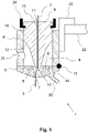
- figure 1 shows a cross-section of a spinneret 1 according to the invention, as used in air-jet spinning machines, which are known in principle from the prior art.
- the spinneret 1 has a housing which comprises at least a first spinneret section 5 and a second spinneret section 6 .
- the first spinneret section 5 and the second spinneret section 6 define an internal vortex chamber 4, into which a yarn-forming element 9 with an internal discharge channel 15 protrudes.
- the yarn-forming element 9 is preferably designed to be rotationally symmetrical with respect to a longitudinal axis 14 shown only in FIG.
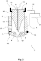
- the guide 12 allows a linear movement of the yarn forming element 9 between the in figure 1 spinning position shown and in the figures 2 and 3 shown cleaning position.
- the yarn forming element 9 is moved, for example, by an actuator 24, which is formed, for example, by one or more levers.
- the first spinneret section 5 has a plurality of air nozzles 8 which are in fluid communication with a connection 19 via a corresponding connection, the connection 19 being designed to be connected to a compressed air line 20 of the air-jet spinning machine.
- compressed air is introduced into the air nozzles 8 via the compressed air line 20 . Since these flow tangentially into the turbulence chamber 4 , a turbulent air flow occurs in the area of the inlet 10 of the yarn-forming element 9 , which causes the fibers of the fiber structure 3 introduced via the inlet opening 7 to rotate.
- a yarn 2 is thus produced from the fiber composite 3, which yarn can be drawn off from the spinneret 1 via the discharge channel 15 and finally the outlet 11 of the yarn-forming element 9.
- the air introduced via the air nozzles 8 escapes primarily via a suction channel 25, which is connected to a corresponding vacuum supply (not shown) of the air-jet spinning machine.
- the spinneret 1 itself is preferably connected via a carrier 22, which is in particular rigidly connected to the second spinneret section 6, on a Mounted holding section 23 of the air spinning machine.
- the movement of the yarn-forming element 9 increases the distance between its inlet 10 and the inlet opening 7 of the spinneret 1 or the first spinneret section 5 .
- Fiber residues that have accumulated on the surface of the yarn-forming element 9 in the area of the inlet 10 can thereby be detached more easily from the yarn-forming element 9 and are finally sucked out of the spinneret 1 via the suction channel 25 .
- the first spinneret section 5 can finally return to its closed position and the yarn-forming element 9 to its spinning position ( figure 1 ) are moved to close the vortex chamber 4 to the outside.
- the movement of the first spinneret section 5 into its closed position can be brought about either manually by the operator or with the aid of an energy store 17 .
- an energy store 17 in the form of a spiral spring is shown as an example, which holds the first spinneret section 5 in its closed position when there is no force applied or moves it back into this position if an external force is not applied in the open position of the first spinneret section 5.
- one or more magnets 18 can be present (see FIG figure 2 ), which fix the first spinneret section 5 in its closed position in the absence of an external force.
- a seal 21 for example in the form of a sealing ring, can be present between the first spinneret section 5 and the second spinneret section 6, via which the first spinneret section 5 rests airtight on the second spinneret section 6 in its closed position.
- the first spinneret section 5 can also be pivoted through an angle ⁇ , the amount of which is preferably between 25° and 120°.
Landscapes
- Engineering & Computer Science (AREA)
- Mechanical Engineering (AREA)
- Textile Engineering (AREA)
- Spinning Methods And Devices For Manufacturing Artificial Fibers (AREA)
Claims (12)
- Filière de filage (1) pour un métier à filer à jet d'air destiné à la fabrication d'un fil (2) à partir d'un ensemble de fibres (3) délivré à la filière de filage (1),- dans laquelle la filière de filage (1) présente une chambre de turbulence (4) disposée à l'intérieur, qui est délimitée au moins partiellement vers l'extérieur par une première section de filière de filage (5) et une deuxième section de filière de filage (6),- dans laquelle la première section de filière de filage (5) comprend une ouverture d'entrée (7) pour l'ensemble de fibres (3) ainsi que plusieurs buses d'air (8) par lesquelles de l'air peut être introduit dans la chambre de turbulence (4),- dans laquelle la filière de filage (1) comporte un élément de formation de fil (9) s'étendant au moins partiellement dans la chambre de turbulence (4), comportant une entrée (10) pour l'ensemble de fibres (3) et une sortie (11) pour le fil (2) produit à l'intérieur de la chambre de turbulence (4) au niveau de l'élément de formation de fil (9) lors du fonctionnement de la filière de filage (1), et- dans laquelle l'élément de formation de fil (9) est maintenu par la deuxième section de filière de filage (6) au moyen d'un guidage (12) et est déplaçable par rapport à la deuxième section de filière de filage (6) entre une position de filage et une position de nettoyage,caractérisée en ce que
la première section de filière de filage (5) est fixée via au moins un axe de pivotement (13) à la deuxième section de filière de filage (6) et peut pivoter autour de l'axe de pivotement (13) d'une position fermée à une position ouverte, dans laquelle l'entrée (10) de l'élément de formation de fil (9) est accessible de l'extérieur à un opérateur uniquement dans la position ouverte, indépendamment de la position de l'élément de formation de fil (9). - Filière de filage (1) selon la revendication précédente, caractérisée en ce que l'axe de pivotement (13) est en liaison fonctionnelle, d'une part, avec la première section de filière de filage (5) et, d'autre part, avec deuxième section de filière de filage (6).
- Filière de filage (1) selon l'une quelconque des revendications précédentes, caractérisée en ce que l'élément de formation de fil (9) est déplaçable par rapport à la deuxième section de filière de filage (6) de manière exclusivement linéaire et, de préférence, colinéaire à un axe longitudinal (14) d'un canal d'extraction (15) reliant l'entrée (10) de l'élément de formation de fil (9) à sa sortie (11).
- Filière de filage (1) selon l'une quelconque des revendications précédentes, caractérisée en ce que le guidage (12) se présente sous la forme d'un alésage, dans lequel l'élément de formation de fil (9) présente dans la zone de l'alésage un contour extérieur cylindrique (16) correspondant à l'alésage, par lequel il est en contact avec le guidage (12).
- Filière de filage (1) selon l'une quelconque des revendications précédentes, caractérisée en ce que la filière de filage (1) présente un accumulateur de force (17) et/ou un aimant (18), à l'aide desquels/duquel la première section de filière de filage (5) est maintenue dans sa position fermée sans application d'une force extérieure.
- Filière de filage (1) selon l'une quelconque des revendications précédentes, caractérisée en ce que la première section de filière de filage (5) peut être pivotée d'un angle α à partir de sa position fermée vers sa position ouverte, l'angle α ayant une valeur qui est comprise entre 25° et 120°.
- Filière de filage (1) selon la revendication précédente, caractérisée en ce que la première section de filière de filage (5) présente un raccord (19) pour une conduite d'air comprimé (20), par lequel les buses d'air (8) peuvent être alimentées en air comprimé.
- Filière de filage (1) selon l'une quelconque des revendications précédentes, caractérisée en ce qu'un joint d'étanchéité (21) est disposé entre la première section de filière de filage (5) et la deuxième section de filière de filage (6), grâce auquel la chambre de turbulence (4), dans la position fermée de la première section de filière de filage (5), est scellée de manière étanche à l'air par rapport à l'environnement de la filière de filage (1) dans la zone de la première section de filière de filage (5).
- Filière de filage (1) selon l'une quelconque des revendications précédentes, caractérisée en ce que la filière de filage (1) présente un support (22) par lequel elle peut être reliée à une section de maintien (23) d'un métier à filer à jet d'air, dans laquelle le support (22) est relié de manière rigide et, de préférence, exclusivement à la deuxième section de filière de filage (6).
- Procédé pour nettoyer une filière de filage (1) à un métier à filer à jet d'air, qui sert à la fabrication d'un fil (2) à partir d'un ensemble de fibres (3) délivré à la filière de filage (1),- dans lequel la filière de filage (1) présente une chambre de turbulence (4) disposée à l'intérieur, qui est délimitée au moins partiellement vers l'extérieur par une première section de filière de filage (5) et une deuxième section de filière de filage (6),- dans lequel la première section de filière de filage (5) comprend une ouverture d'entrée (7) pour l'ensemble de fibres (3) ainsi que plusieurs buses d'air (8) par lesquelles, lors du fonctionnement de la filière de filage (1), de l'air est introduit dans la chambre de turbulence (4),- dans lequel la filière de filage (1) comporte un élément de formation de fil (9) s'étendant au moins partiellement dans la chambre de turbulence (4), comportant une entrée (10) pour l'ensemble de fibres (3) et une sortie (11) pour le fil (2) produit à l'intérieur de la chambre de turbulence (4) au niveau de l'élément de formation de fil (9) lors du fonctionnement de la filière de filage (1), et- dans lequel l'élément de formation de fil (9) est déplacé par rapport à la deuxième section de filière de filage (6) d'une position de filage à une position de nettoyage avant ou pendant l'ouverture de la filière de filage (1),caractérisé en ce que
la première section de filière de filage (5), pendant l'ouverture de la filière de filage (1), est pivotée autour d'un axe de pivotement (13) d'une position fermée à une position ouverte, dans lequel l'entrée (10) de l'élément de formation de fil (9) est accessible de l'extérieur à un opérateur uniquement dans la position ouverte, indépendamment de la position de l'élément de formation de fil (9), et dans lequel l'élément de formation de fil (9) est nettoyé par un opérateur après le pivotement de la première section de filière de filage (5). - Procédé selon la revendication précédente, caractérisé en ce que le mouvement de l'élément de formation de fil (9) est effectué à l'aide d'un actionneur (24) du métier à filer à jet d'air et le pivotement de la première section de filière de filage (5) est effectué manuellement par l'opérateur.
- Procédé selon la revendication 10 ou 11, caractérisé en ce que la chambre de turbulence (4) est soumise à une dépression par l'intermédiaire d'un canal d'aspiration (25) de la filière de filage (1) lorsque l'élément de formation de fil (9) se trouve dans sa position de nettoyage, afin d'aspirer les restes de fibres hors de la chambre de turbulence (4), dans lequel, dans ce contexte, de l'air provenant de l'environnement est aspiré dans la chambre de turbulence (4) par l'ouverture d'entrée (7) de la filière de filage (1).
Applications Claiming Priority (1)
| Application Number | Priority Date | Filing Date | Title |
|---|---|---|---|
| DE102018130826.4A DE102018130826A1 (de) | 2018-12-04 | 2018-12-04 | Spinndüse sowie Verfahren zum Reinigen derselben |
Publications (2)
| Publication Number | Publication Date |
|---|---|
| EP3663445A1 EP3663445A1 (fr) | 2020-06-10 |
| EP3663445B1 true EP3663445B1 (fr) | 2023-01-25 |
Family
ID=68771405
Family Applications (1)
| Application Number | Title | Priority Date | Filing Date |
|---|---|---|---|
| EP19213386.6A Active EP3663445B1 (fr) | 2018-12-04 | 2019-12-04 | Buse de filage ainsi que procédé de nettoyage d'une telle buse de filage |
Country Status (3)
| Country | Link |
|---|---|
| EP (1) | EP3663445B1 (fr) |
| CN (1) | CN111270359B (fr) |
| DE (1) | DE102018130826A1 (fr) |
Families Citing this family (2)
| Publication number | Priority date | Publication date | Assignee | Title |
|---|---|---|---|---|
| EP4015681B1 (fr) * | 2020-12-18 | 2025-01-29 | Saurer Intelligent Technology AG | Poste de filage doté d'une buse de nettoyage et procédé de nettoyage d'un élément de formation de fil |
| CN113122970B (zh) * | 2021-05-14 | 2022-02-11 | 无锡高仕康新材料科技有限公司 | 51mm中长纤维芳纶涡流纺纱制备装置及其工艺 |
Family Cites Families (8)
| Publication number | Priority date | Publication date | Assignee | Title |
|---|---|---|---|---|
| EP1072702B1 (fr) * | 1999-07-28 | 2004-03-31 | Murata Kikai Kabushiki Kaisha | Dispositif de filage et procédé à filer |
| JP2001131834A (ja) * | 1999-08-24 | 2001-05-15 | Murata Mach Ltd | 紡績装置 |
| DE102008050874A1 (de) * | 2008-09-29 | 2010-04-01 | Wilhelm Stahlecker Gmbh | Luftdüsenspinnaggregat mit spindelförmigem Bauteil |
| JP2011038210A (ja) * | 2009-08-11 | 2011-02-24 | Murata Machinery Ltd | 空気紡績装置及びこの空気紡績装置を備える紡績機 |
| JP2013067895A (ja) | 2011-09-21 | 2013-04-18 | Murata Mach Ltd | 紡績ユニット及び紡績機 |
| DE102015100825A1 (de) | 2015-01-21 | 2016-07-21 | Maschinenfabrik Rieter Ag | Spinndüse einer Luftspinnmaschine sowie Verfahren zum Öffnen derselben |
| CH713499A2 (de) * | 2017-02-28 | 2018-08-31 | Rieter Ag Maschf | Luftspinnmaschine zur Herstellung eines Garns aus einem strangförmigen Faserverband. |
| DE102017113257A1 (de) * | 2017-06-16 | 2018-12-20 | Maschinenfabrik Rieter Ag | Arbeitsstelle einer Luftspinnmaschine sowie Verfahren zum Öffnen einer Spinndüse |
-
2018
- 2018-12-04 DE DE102018130826.4A patent/DE102018130826A1/de not_active Withdrawn
-
2019
- 2019-12-03 CN CN201911218953.4A patent/CN111270359B/zh active Active
- 2019-12-04 EP EP19213386.6A patent/EP3663445B1/fr active Active
Also Published As
| Publication number | Publication date |
|---|---|
| DE102018130826A1 (de) | 2020-06-04 |
| CN111270359B (zh) | 2023-01-17 |
| EP3663445A1 (fr) | 2020-06-10 |
| CN111270359A (zh) | 2020-06-12 |
Similar Documents
| Publication | Publication Date | Title |
|---|---|---|
| EP2620532B1 (fr) | Métier à tisser à jet d'air avec organe de nettoyage ainsi que procédé de nettoyage de la chambre tourbillonnaire d'un métier à tisser à jet d'air | |
| EP2329066B1 (fr) | Groupe de filature a buse d'air comprenant un composant en forme de broche | |
| EP3048191B1 (fr) | Buse d'un metier a filer a jet d'air et son procede d'ouverture | |
| EP2957662B1 (fr) | Dispositif de filage à bout libre d'une chambre intermédiaire | |
| EP3663445B1 (fr) | Buse de filage ainsi que procédé de nettoyage d'une telle buse de filage | |
| DE102015108558A1 (de) | Luftfilter | |
| EP1786961A1 (fr) | Dispositif de filature a jet d'air | |
| EP3449048A1 (fr) | Métier à filer à jet d'air et procédé de production d'un fil | |
| DE19544617B4 (de) | Adapter für Offenend-Spinnvorrichtungen | |
| WO2018228864A1 (fr) | Poste de travail d'un métier à filer à jet d'air ainsi que procédé servant à ouvrir une filière | |
| CH713499A2 (de) | Luftspinnmaschine zur Herstellung eines Garns aus einem strangförmigen Faserverband. | |
| EP3530782B1 (fr) | Procédé de fonctionnement d'un dispositif de filage d'un métier à filer à rotor et dispositif de filage d'un métier à filer à rotor | |
| CH688154A5 (de) | Offenend-Spinneinheit mit einer im Bereich eines Aufl¦sewalzengehaeuses angeordneten Schmutzkammer. | |
| EP3293294B1 (fr) | Élément de formation de fil et buse de filage pour un métier à filer à jet d'air | |
| WO2018087054A1 (fr) | Filière pour machine à filer à jet d'air et procédé de fonctionnement de celle-ci | |
| DE102016117302A1 (de) | Verfahren zum Betreiben einer Textilmaschine und Textilmaschine | |
| DE19718768A1 (de) | Verfahren und Vorrichtung zum pneumatischen Reinigen eines Fadenabzugsrohres | |
| EP3133193A1 (fr) | Dispositif d'aspiration comprenant une chambre collectrice d'impuretes | |
| WO2020165044A1 (fr) | Filière pour machine à filer à jet d'air et procédé pour ouvrir une telle filière | |
| EP4043625A1 (fr) | Élément de filature | |
| DE3825327A1 (de) | Vorrichtung und verfahren zum speichern eines fadens | |
| EP4050138B1 (fr) | Procédé de fonctionnement d'un poste de travail d'un métier à filer et poste de travail | |
| DE10150565A1 (de) | Verfahren und Vorrichtung zur Vorbereitung eines abgelängten Fadenendes für das Wiederanspinnen einer Offenend-Spinnvorrichtung | |
| DE102006018242A1 (de) | Luftdüsenspinnvorrichtung | |
| DE3913244A1 (de) | Spinnduese zur pneumatischen garnherstellung |
Legal Events
| Date | Code | Title | Description |
|---|---|---|---|
| PUAI | Public reference made under article 153(3) epc to a published international application that has entered the european phase |
Free format text: ORIGINAL CODE: 0009012 |
|
| STAA | Information on the status of an ep patent application or granted ep patent |
Free format text: STATUS: THE APPLICATION HAS BEEN PUBLISHED |
|
| AK | Designated contracting states |
Kind code of ref document: A1 Designated state(s): AL AT BE BG CH CY CZ DE DK EE ES FI FR GB GR HR HU IE IS IT LI LT LU LV MC MK MT NL NO PL PT RO RS SE SI SK SM TR |
|
| AX | Request for extension of the european patent |
Extension state: BA ME |
|
| STAA | Information on the status of an ep patent application or granted ep patent |
Free format text: STATUS: REQUEST FOR EXAMINATION WAS MADE |
|
| 17P | Request for examination filed |
Effective date: 20201130 |
|
| RBV | Designated contracting states (corrected) |
Designated state(s): AL AT BE BG CH CY CZ DE DK EE ES FI FR GB GR HR HU IE IS IT LI LT LU LV MC MK MT NL NO PL PT RO RS SE SI SK SM TR |
|
| GRAP | Despatch of communication of intention to grant a patent |
Free format text: ORIGINAL CODE: EPIDOSNIGR1 |
|
| STAA | Information on the status of an ep patent application or granted ep patent |
Free format text: STATUS: GRANT OF PATENT IS INTENDED |
|
| INTG | Intention to grant announced |
Effective date: 20220708 |
|
| GRAS | Grant fee paid |
Free format text: ORIGINAL CODE: EPIDOSNIGR3 |
|
| GRAA | (expected) grant |
Free format text: ORIGINAL CODE: 0009210 |
|
| STAA | Information on the status of an ep patent application or granted ep patent |
Free format text: STATUS: THE PATENT HAS BEEN GRANTED |
|
| AK | Designated contracting states |
Kind code of ref document: B1 Designated state(s): AL AT BE BG CH CY CZ DE DK EE ES FI FR GB GR HR HU IE IS IT LI LT LU LV MC MK MT NL NO PL PT RO RS SE SI SK SM TR |
|
| REG | Reference to a national code |
Ref country code: GB Ref legal event code: FG4D Free format text: NOT ENGLISH |
|
| REG | Reference to a national code |
Ref country code: CH Ref legal event code: EP |
|
| REG | Reference to a national code |
Ref country code: DE Ref legal event code: R096 Ref document number: 502019006866 Country of ref document: DE |
|
| REG | Reference to a national code |
Ref country code: AT Ref legal event code: REF Ref document number: 1545965 Country of ref document: AT Kind code of ref document: T Effective date: 20230215 Ref country code: IE Ref legal event code: FG4D Free format text: LANGUAGE OF EP DOCUMENT: GERMAN |
|
| REG | Reference to a national code |
Ref country code: LT Ref legal event code: MG9D |
|
| REG | Reference to a national code |
Ref country code: NL Ref legal event code: MP Effective date: 20230125 |
|
| P01 | Opt-out of the competence of the unified patent court (upc) registered |
Effective date: 20230329 |
|
| PG25 | Lapsed in a contracting state [announced via postgrant information from national office to epo] |
Ref country code: NL Free format text: LAPSE BECAUSE OF FAILURE TO SUBMIT A TRANSLATION OF THE DESCRIPTION OR TO PAY THE FEE WITHIN THE PRESCRIBED TIME-LIMIT Effective date: 20230125 |
|
| PG25 | Lapsed in a contracting state [announced via postgrant information from national office to epo] |
Ref country code: RS Free format text: LAPSE BECAUSE OF FAILURE TO SUBMIT A TRANSLATION OF THE DESCRIPTION OR TO PAY THE FEE WITHIN THE PRESCRIBED TIME-LIMIT Effective date: 20230125 Ref country code: PT Free format text: LAPSE BECAUSE OF FAILURE TO SUBMIT A TRANSLATION OF THE DESCRIPTION OR TO PAY THE FEE WITHIN THE PRESCRIBED TIME-LIMIT Effective date: 20230525 Ref country code: NO Free format text: LAPSE BECAUSE OF FAILURE TO SUBMIT A TRANSLATION OF THE DESCRIPTION OR TO PAY THE FEE WITHIN THE PRESCRIBED TIME-LIMIT Effective date: 20230425 Ref country code: LV Free format text: LAPSE BECAUSE OF FAILURE TO SUBMIT A TRANSLATION OF THE DESCRIPTION OR TO PAY THE FEE WITHIN THE PRESCRIBED TIME-LIMIT Effective date: 20230125 Ref country code: LT Free format text: LAPSE BECAUSE OF FAILURE TO SUBMIT A TRANSLATION OF THE DESCRIPTION OR TO PAY THE FEE WITHIN THE PRESCRIBED TIME-LIMIT Effective date: 20230125 Ref country code: HR Free format text: LAPSE BECAUSE OF FAILURE TO SUBMIT A TRANSLATION OF THE DESCRIPTION OR TO PAY THE FEE WITHIN THE PRESCRIBED TIME-LIMIT Effective date: 20230125 Ref country code: ES Free format text: LAPSE BECAUSE OF FAILURE TO SUBMIT A TRANSLATION OF THE DESCRIPTION OR TO PAY THE FEE WITHIN THE PRESCRIBED TIME-LIMIT Effective date: 20230125 |
|
| PG25 | Lapsed in a contracting state [announced via postgrant information from national office to epo] |
Ref country code: SE Free format text: LAPSE BECAUSE OF FAILURE TO SUBMIT A TRANSLATION OF THE DESCRIPTION OR TO PAY THE FEE WITHIN THE PRESCRIBED TIME-LIMIT Effective date: 20230125 Ref country code: PL Free format text: LAPSE BECAUSE OF FAILURE TO SUBMIT A TRANSLATION OF THE DESCRIPTION OR TO PAY THE FEE WITHIN THE PRESCRIBED TIME-LIMIT Effective date: 20230125 Ref country code: IS Free format text: LAPSE BECAUSE OF FAILURE TO SUBMIT A TRANSLATION OF THE DESCRIPTION OR TO PAY THE FEE WITHIN THE PRESCRIBED TIME-LIMIT Effective date: 20230525 Ref country code: GR Free format text: LAPSE BECAUSE OF FAILURE TO SUBMIT A TRANSLATION OF THE DESCRIPTION OR TO PAY THE FEE WITHIN THE PRESCRIBED TIME-LIMIT Effective date: 20230426 Ref country code: FI Free format text: LAPSE BECAUSE OF FAILURE TO SUBMIT A TRANSLATION OF THE DESCRIPTION OR TO PAY THE FEE WITHIN THE PRESCRIBED TIME-LIMIT Effective date: 20230125 |
|
| REG | Reference to a national code |
Ref country code: DE Ref legal event code: R097 Ref document number: 502019006866 Country of ref document: DE |
|
| PG25 | Lapsed in a contracting state [announced via postgrant information from national office to epo] |
Ref country code: SM Free format text: LAPSE BECAUSE OF FAILURE TO SUBMIT A TRANSLATION OF THE DESCRIPTION OR TO PAY THE FEE WITHIN THE PRESCRIBED TIME-LIMIT Effective date: 20230125 Ref country code: RO Free format text: LAPSE BECAUSE OF FAILURE TO SUBMIT A TRANSLATION OF THE DESCRIPTION OR TO PAY THE FEE WITHIN THE PRESCRIBED TIME-LIMIT Effective date: 20230125 Ref country code: EE Free format text: LAPSE BECAUSE OF FAILURE TO SUBMIT A TRANSLATION OF THE DESCRIPTION OR TO PAY THE FEE WITHIN THE PRESCRIBED TIME-LIMIT Effective date: 20230125 Ref country code: DK Free format text: LAPSE BECAUSE OF FAILURE TO SUBMIT A TRANSLATION OF THE DESCRIPTION OR TO PAY THE FEE WITHIN THE PRESCRIBED TIME-LIMIT Effective date: 20230125 Ref country code: CZ Free format text: LAPSE BECAUSE OF FAILURE TO SUBMIT A TRANSLATION OF THE DESCRIPTION OR TO PAY THE FEE WITHIN THE PRESCRIBED TIME-LIMIT Effective date: 20230125 |
|
| PG25 | Lapsed in a contracting state [announced via postgrant information from national office to epo] |
Ref country code: SK Free format text: LAPSE BECAUSE OF FAILURE TO SUBMIT A TRANSLATION OF THE DESCRIPTION OR TO PAY THE FEE WITHIN THE PRESCRIBED TIME-LIMIT Effective date: 20230125 |
|
| PLBE | No opposition filed within time limit |
Free format text: ORIGINAL CODE: 0009261 |
|
| STAA | Information on the status of an ep patent application or granted ep patent |
Free format text: STATUS: NO OPPOSITION FILED WITHIN TIME LIMIT |
|
| 26N | No opposition filed |
Effective date: 20231026 |
|
| PG25 | Lapsed in a contracting state [announced via postgrant information from national office to epo] |
Ref country code: SI Free format text: LAPSE BECAUSE OF FAILURE TO SUBMIT A TRANSLATION OF THE DESCRIPTION OR TO PAY THE FEE WITHIN THE PRESCRIBED TIME-LIMIT Effective date: 20230125 |
|
| REG | Reference to a national code |
Ref country code: CH Ref legal event code: PL |
|
| PG25 | Lapsed in a contracting state [announced via postgrant information from national office to epo] |
Ref country code: LU Free format text: LAPSE BECAUSE OF NON-PAYMENT OF DUE FEES Effective date: 20231204 |
|
| PG25 | Lapsed in a contracting state [announced via postgrant information from national office to epo] |
Ref country code: MC Free format text: LAPSE BECAUSE OF FAILURE TO SUBMIT A TRANSLATION OF THE DESCRIPTION OR TO PAY THE FEE WITHIN THE PRESCRIBED TIME-LIMIT Effective date: 20230125 |
|
| GBPC | Gb: european patent ceased through non-payment of renewal fee |
Effective date: 20231204 |
|
| REG | Reference to a national code |
Ref country code: BE Ref legal event code: MM Effective date: 20231231 |
|
| PG25 | Lapsed in a contracting state [announced via postgrant information from national office to epo] |
Ref country code: MC Free format text: LAPSE BECAUSE OF FAILURE TO SUBMIT A TRANSLATION OF THE DESCRIPTION OR TO PAY THE FEE WITHIN THE PRESCRIBED TIME-LIMIT Effective date: 20230125 Ref country code: LU Free format text: LAPSE BECAUSE OF NON-PAYMENT OF DUE FEES Effective date: 20231204 |
|
| REG | Reference to a national code |
Ref country code: IE Ref legal event code: MM4A |
|
| PG25 | Lapsed in a contracting state [announced via postgrant information from national office to epo] |
Ref country code: IE Free format text: LAPSE BECAUSE OF NON-PAYMENT OF DUE FEES Effective date: 20231204 |
|
| PG25 | Lapsed in a contracting state [announced via postgrant information from national office to epo] |
Ref country code: GB Free format text: LAPSE BECAUSE OF NON-PAYMENT OF DUE FEES Effective date: 20231204 |
|
| PG25 | Lapsed in a contracting state [announced via postgrant information from national office to epo] |
Ref country code: BE Free format text: LAPSE BECAUSE OF NON-PAYMENT OF DUE FEES Effective date: 20231231 |
|
| PG25 | Lapsed in a contracting state [announced via postgrant information from national office to epo] |
Ref country code: FR Free format text: LAPSE BECAUSE OF NON-PAYMENT OF DUE FEES Effective date: 20231231 |
|
| PG25 | Lapsed in a contracting state [announced via postgrant information from national office to epo] |
Ref country code: CH Free format text: LAPSE BECAUSE OF NON-PAYMENT OF DUE FEES Effective date: 20231231 |
|
| PG25 | Lapsed in a contracting state [announced via postgrant information from national office to epo] |
Ref country code: IE Free format text: LAPSE BECAUSE OF NON-PAYMENT OF DUE FEES Effective date: 20231204 Ref country code: GB Free format text: LAPSE BECAUSE OF NON-PAYMENT OF DUE FEES Effective date: 20231204 Ref country code: FR Free format text: LAPSE BECAUSE OF NON-PAYMENT OF DUE FEES Effective date: 20231231 Ref country code: CH Free format text: LAPSE BECAUSE OF NON-PAYMENT OF DUE FEES Effective date: 20231231 Ref country code: BE Free format text: LAPSE BECAUSE OF NON-PAYMENT OF DUE FEES Effective date: 20231231 |
|
| PG25 | Lapsed in a contracting state [announced via postgrant information from national office to epo] |
Ref country code: BG Free format text: LAPSE BECAUSE OF FAILURE TO SUBMIT A TRANSLATION OF THE DESCRIPTION OR TO PAY THE FEE WITHIN THE PRESCRIBED TIME-LIMIT Effective date: 20230125 |
|
| PG25 | Lapsed in a contracting state [announced via postgrant information from national office to epo] |
Ref country code: BG Free format text: LAPSE BECAUSE OF FAILURE TO SUBMIT A TRANSLATION OF THE DESCRIPTION OR TO PAY THE FEE WITHIN THE PRESCRIBED TIME-LIMIT Effective date: 20230125 |
|
| PG25 | Lapsed in a contracting state [announced via postgrant information from national office to epo] |
Ref country code: CY Free format text: LAPSE BECAUSE OF FAILURE TO SUBMIT A TRANSLATION OF THE DESCRIPTION OR TO PAY THE FEE WITHIN THE PRESCRIBED TIME-LIMIT; INVALID AB INITIO Effective date: 20191204 |
|
| PG25 | Lapsed in a contracting state [announced via postgrant information from national office to epo] |
Ref country code: HU Free format text: LAPSE BECAUSE OF FAILURE TO SUBMIT A TRANSLATION OF THE DESCRIPTION OR TO PAY THE FEE WITHIN THE PRESCRIBED TIME-LIMIT; INVALID AB INITIO Effective date: 20191204 |
|
| REG | Reference to a national code |
Ref country code: AT Ref legal event code: MM01 Ref document number: 1545965 Country of ref document: AT Kind code of ref document: T Effective date: 20241204 |
|
| PGFP | Annual fee paid to national office [announced via postgrant information from national office to epo] |
Ref country code: DE Payment date: 20251230 Year of fee payment: 7 |
|
| PG25 | Lapsed in a contracting state [announced via postgrant information from national office to epo] |
Ref country code: AT Free format text: LAPSE BECAUSE OF NON-PAYMENT OF DUE FEES Effective date: 20241204 |
|
| PGFP | Annual fee paid to national office [announced via postgrant information from national office to epo] |
Ref country code: AT Payment date: 20260410 Year of fee payment: 5 |