EP4015681B1 - Poste de filage doté d'une buse de nettoyage et procédé de nettoyage d'un élément de formation de fil - Google Patents
Poste de filage doté d'une buse de nettoyage et procédé de nettoyage d'un élément de formation de fil Download PDFInfo
- Publication number
- EP4015681B1 EP4015681B1 EP20215332.6A EP20215332A EP4015681B1 EP 4015681 B1 EP4015681 B1 EP 4015681B1 EP 20215332 A EP20215332 A EP 20215332A EP 4015681 B1 EP4015681 B1 EP 4015681B1
- Authority
- EP
- European Patent Office
- Prior art keywords
- cleaning
- yarn
- forming element
- nozzle
- air
- Prior art date
- Legal status (The legal status is an assumption and is not a legal conclusion. Google has not performed a legal analysis and makes no representation as to the accuracy of the status listed.)
- Active
Links
Images


Classifications
-
- D—TEXTILES; PAPER
- D01—NATURAL OR MAN-MADE THREADS OR FIBRES; SPINNING
- D01H—SPINNING OR TWISTING
- D01H1/00—Spinning or twisting machines in which the product is wound-up continuously
- D01H1/11—Spinning by false-twisting
- D01H1/115—Spinning by false-twisting using pneumatic means
-
- D—TEXTILES; PAPER
- D01—NATURAL OR MAN-MADE THREADS OR FIBRES; SPINNING
- D01H—SPINNING OR TWISTING
- D01H11/00—Arrangements for confining or removing dust, fly or the like
-
- D—TEXTILES; PAPER
- D01—NATURAL OR MAN-MADE THREADS OR FIBRES; SPINNING
- D01H—SPINNING OR TWISTING
- D01H11/00—Arrangements for confining or removing dust, fly or the like
- D01H11/005—Arrangements for confining or removing dust, fly or the like with blowing and/or suction devices
-
- D—TEXTILES; PAPER
- D01—NATURAL OR MAN-MADE THREADS OR FIBRES; SPINNING
- D01H—SPINNING OR TWISTING
- D01H4/00—Open-end spinning machines or arrangements for imparting twist to independently moving fibres separated from slivers; Piecing arrangements therefor; Covering endless core threads with fibres by open-end spinning techniques
- D01H4/02—Open-end spinning machines or arrangements for imparting twist to independently moving fibres separated from slivers; Piecing arrangements therefor; Covering endless core threads with fibres by open-end spinning techniques imparting twist by a fluid, e.g. air vortex
-
- D—TEXTILES; PAPER
- D01—NATURAL OR MAN-MADE THREADS OR FIBRES; SPINNING
- D01H—SPINNING OR TWISTING
- D01H2700/00—Spinning or twisting machines; Drafting devices
- D01H2700/21—Piecing or cleaning in spinning mules
-
- D—TEXTILES; PAPER
- D01—NATURAL OR MAN-MADE THREADS OR FIBRES; SPINNING
- D01H—SPINNING OR TWISTING
- D01H4/00—Open-end spinning machines or arrangements for imparting twist to independently moving fibres separated from slivers; Piecing arrangements therefor; Covering endless core threads with fibres by open-end spinning techniques
- D01H4/04—Open-end spinning machines or arrangements for imparting twist to independently moving fibres separated from slivers; Piecing arrangements therefor; Covering endless core threads with fibres by open-end spinning techniques imparting twist by contact of fibres with a running surface
- D01H4/22—Cleaning of running surfaces
Definitions
- the invention relates to a spinning station of an air spinning machine and a method for cleaning a yarn forming element of an air spinning nozzle.
- a drafting sliver is drawn in a defined manner using a multi-roll drafting system according to the yarn fineness to be achieved and then fed to an air spinning nozzle.
- the outer fibers of the fiber sliver are wound around an inner fiber core by means of a swirl air flow generated by air nozzles in the area of an inlet opening of a yarn forming element of the air spinning nozzle, so that an air yarn-specific yarn structure of a parallel yarn core and wrapped fibers lying at a certain angle is produced, whereby the wrapped fibers are crucial for the desired strength of the yarn.
- the air spinning process can basically be carried out with fibers made of different materials, whereby both natural fibers such as cotton and/or animal wool and synthetic fibers such as polyester as well as mixtures of natural and synthetic fibers can be used.
- natural fibers such as cotton and/or animal wool
- synthetic fibers such as polyester as well as mixtures of natural and synthetic fibers
- deposits of polymer residues, polyester fiber fragments and/or finishing agents often occur on a surface of a spinning cone of the yarn forming element.
- deposits significantly disrupt the air spinning process and significantly reduce the spinning result and thus the yarn quality.
- thread breaks can occur during the spinning process due to the increased friction between the surfaces of the air spinneret and the fibers.
- the air nozzles and other components of the air spinneret can become clogged by deposits, so that the yarn obtained has a lower yarn strength and quality.
- the invention is therefore based on the object of providing a spinning station of an air spinning machine and a method for cleaning a yarn forming element of an air spinning nozzle, which enable particularly long and trouble-free operation with consistent quality and strength of the yarn produced.
- the spinning station of an air spinning machine has an air spinning nozzle with a yarn forming element arranged within a vortex chamber for producing a yarn from a fiber band fed to the air spinning nozzle, wherein the air spinning nozzle can be transferred from a closed state for yarn formation to an open state in which the yarn forming element can be cleaned.
- At least one cleaning nozzle for cleaning the yarn forming element in the open state of the air spinning nozzle is assigned to the spinning station or arranged at the spinning station, wherein the cleaning nozzle is designed in such a way, in particular positioned and/or aligned or positionable and/or alignable in such a way that at least in the open state of the air spinning nozzle the yarn forming element can be exposed to a cleaning medium through the cleaning nozzle.
- the air spinneret having a swirl chamber is first opened to make the yarn-forming element arranged in the swirl chamber accessible, then and/or at the same time the yarn-forming element and/or a cleaning nozzle is moved into a cleaning position and finally the yarn-forming element is exposed to at least one cleaning medium.
- the inventors have recognized that regular cleaning of the yarn forming element enables long and trouble-free operation with consistent quality and strength of the yarn produced, whereby such cleaning is possible in a particularly simple manner and without disturbing the other components of the air spinning machine when the air spinning nozzle is in an open position, for example during a spinning interruption after a thread break or a planned cut of the yarn.
- the invention advantageously allows an increase in strength and greater cleanliness of the spun yarns.
- An air spinneret is understood to be any spinneret that uses at least one air stream to swirl fibers, in particular wrapped fibers, around an internal fiber core to form a thread or yarn.
- the yarn formation process takes place in the area of a swirl chamber of the air spinneret, in which at least one yarn formation element is arranged.
- the air spinneret is surrounded by a spinning station, with each spinning station serving to produce a yarn from a fiber sliver fed to the air spinneret.
- the air spinneret has an inlet for the fiber sliver, the internal swirl chamber, one or more yarn formation or spinning elements arranged at least in sections in the swirl chamber, and an outlet for the yarn produced inside the swirl chamber.
- the air spinneret preferably has a plurality of air nozzles opening into the vortex chamber, which are particularly preferably in fluid communication with at least one air supply line, wherein during a spinning operation of the spinning station, in which the yarn is produced by means of the air spinneret, compressed air provided by the air supply line flows into the vortex chamber via the air nozzles in order to generate a vortex air flow within the vortex chamber for air spinning the supplied fiber sliver into a yarn.
- a yarn or thread in the sense of the invention is a fiber structure in which at least some of the fibers are wound around an internal fiber core.
- a yarn can also be a roving or a sliver for further processing, for example using a ring spinning machine.
- the fiber band and thus the yarn produced from it is preferably made at least partially, particularly preferably completely, from synthetic fibers or chemical fibers, for example from polyester or polyethersulfone.
- the sliver is basically the fiber material fed into the air spinning process, which is preferably provided as a continuous sliver or composite of fibers to be spun. All fibers can be made of the same material or the sliver can contain chemically different fibers. In principle, however, the fibers in the sliver are not yet spun together.
- the yarn forming element can be either an independent component or a section of a
- the yarn forming element can be a structural unit or a functional unit that is directly involved in the air spinning process.
- the yarn forming element can be formed in one piece or in multiple pieces.
- the yarn forming element preferably has a spinning cone or part of a spinning cone and the yarn forming element most preferably forms the spinning cone. During the air spinning process, the yarn forming element comes into direct contact, at least in sections, with the fibers to be spun to produce the yarn and with the spun yarn.
- the air spinneret can be converted from a closed state of the air spinneret, in which the swirl chamber is preferably formed by the air spinneret and the yarn forming element arranged in the swirl chamber is surrounded by the swirl chamber, into an open state in which the swirl chamber is preferably opened relative to the external environment of the air spinneret and the yarn forming element is exposed for cleaning, for which purpose at least a first component of the air spinneret, which more preferably comprises the yarn forming element, can be moved relative to another component of the air spinneret.
- the first and second components of the air spinneret in particular have wall sections which at least partially delimit the swirl chamber when the air spinneret is closed.
- the first component of the air spinneret which particularly preferably comprises the yarn forming element, is preferably moved, in particular shifted and/or pivoted, relative to the second component of the air spinneret, which is preferably arranged stationary at the spinning station.
- the closed state of the air spinneret is intended for yarn formation, while in the open state of the air spinneret the yarn formation element is at least partially and particularly preferably completely accessible for cleaning.
- the opening of the air spinneret and the movement of the yarn forming element and/or preferably the cleaning nozzle can take place either completely one after the other or at least partially at the same time. It is also conceivable that the yarn forming element is moved into a cleaning position at the same time as or immediately after the opening of the air spinneret, in which case a movement of the cleaning nozzle into a cleaning position is not necessary but is preferably additionally possible.
- the cleaning position is the position of the yarn forming element and/or the cleaning nozzle in which the yarn forming element is cleaned by at least one cleaning medium using the cleaning nozzle.
- the cleaning position of the cleaning nozzle is preferably located outside the vortex chamber and/or opposite a surface of the yarn forming element.
- the cleaning position is provided for operating the cleaning nozzle, with the cleaning nozzle preferably being operated exclusively in the cleaning position.
- the spinning station and/or the air spinning machine is arranged in an exposure path between an outer surface of the yarn forming element and the at least one cleaning nozzle, particularly preferably all of the cleaning nozzles.
- cleaning can be carried out in any manner using the cleaning nozzle, with the cleaning method preferably comprising a fixed cleaning cycle, which is in particular composed of several cleaning steps.
- Cleaning preferably means the removal of dirt from the yarn-forming element, in particular fiber, finish and/or polymer deposits.
- the dirt is particularly preferably removed from the outer surface of the yarn-forming element and/or at least part of a thread withdrawal channel inside the yarn-forming element.
- a cleaning nozzle for dispensing a cleaning medium and for supplying the cleaning medium to the yarn forming element.
- the cleaning nozzle is arranged at the spinning station and/or directed towards the spinning station.
- at least one cleaning nozzle is assigned to two spinning stations, more preferably to a single spinning station.
- the cleaning nozzle can preferably be arranged in the area of two adjacent spinning stations in such a way that the cleaning nozzle can apply a cleaning medium to the respective yarn forming element of these two spinning stations. More preferably, a cleaning nozzle is arranged at each spinning station.
- the cleaning nozzle is a nozzle for cleaning the yarn forming element using a liquid and/or a gas.
- the cleaning medium can be either a gas or a liquid.
- any mixtures of gases and liquids, in particular aerosols, foams and/or emulsions, are also conceivable as a cleaning medium.
- the cleaning nozzle is also preferably designed to apply the cleaning medium to at least one surface section of the yarn forming element using atomizer technology.
- the cleaning nozzle particularly preferably has a liquid atomizer and most preferably the cleaning nozzle is designed as a liquid atomizer.
- the cleaning nozzle is designed, in particular positioned and/or aligned or positionable and/or alignable, such that the yarn-forming element can be subjected to the cleaning medium in the cleaning position.
- Subjecting it to cleaning medium means that a cleaning medium is guided onto at least a part or a section of the surface of the yarn-forming element.
- the supply of at least one cleaning medium to the cleaning nozzle preferably takes place via at least one cleaning medium line, which can be designed as a pure liquid line, as a pure gas line or alternatively as a mixed line. Furthermore, in particular the supply of gases and liquids as cleaning medium can take place via different or separate lines.
- an activation and/or dosing unit is arranged in front of the cleaning nozzle, which is particularly preferably designed as a valve and/or as an adjustable throttle in order to be able to regulate the amount or flow of the cleaning medium supplied to the yarn formation element in a defined manner.
- a cleaning nozzle is arranged outside the swirl chamber and/or stationary at or in the area of the spinning station, whereby a particularly simple structure can be achieved and the air spinning process is not disturbed by the cleaning nozzle.
- a cleaning nozzle can be moved by means of a pivoting device between a rest position and a cleaning position for cleaning the yarn formation element, which enables particularly uninterrupted operation of the spinning station.
- the movement between the rest position and the cleaning position is preferably a displacement, in particular an extension, and/or a folding or pivoting.
- an advantageous design of the spinning station with several cleaning nozzles is conceivable.
- the cleaning nozzle can be positioned and aligned by means of the pivoting device in such a way that the yarn forming element can be exposed to the cleaning medium at least partially from the front and/or side in the cleaning position, whereby cleaning of the yarn forming element can be achieved in a particularly simple manner.
- Frontal means in particular in a direction along a yarn withdrawal channel and/or in the direction of a tip of the yarn forming element.
- Lateral means in particular from one side orthogonal to a yarn withdrawal channel arranged centrally in the yarn forming element and/or aligned towards a part of a preferably conical side surface of the yarn forming element.
- the cleaning nozzle can be rotated by means of the pivoting device, at least in sections, preferably completely around the yarn forming element, in order to be able to apply the cleaning medium to the entire surface of the yarn forming element, in particular a spinning cone surface, during rotation.
- the rotation of the cleaning nozzle can take place both at right angles to a central longitudinal axis or a yarn withdrawal channel of the yarn forming element, as well as at a constant or variable angle, with rotation along a circular path or along a circular section being preferred. becomes.
- the method for cleaning a yarn forming element provides that the cleaning nozzle for cleaning the yarn forming element is moved by means of a pivoting device from a rest position to a cleaning position and/or after cleaning from the cleaning position to the rest position.
- this movement to the cleaning position can take place at any time.
- the yarn forming element is moved to the cleaning position when the opening process of the air spinning nozzle is initiated, during the opening of the air spinning nozzle and/or after the opening of the air spinning nozzle.
- the yarn forming element is moved to the cleaning position in such a way that the cleaning nozzle is in the cleaning position before or at the end of the opening process, which enables particularly time-efficient cleaning.
- a preferred embodiment of the method for cleaning a yarn forming element provides for cleaning a yarn forming element during a spinning interruption, for example after at least one or every thread break, after at least one or every cut of the yarn, during removal of a winding package wound using the air-spun yarn and/or during a spinning can change from which the sliver is fed to the spinning station. Cleaning after a thread break makes it possible in particular for contamination as a possible reason for a thread break to be removed before the air-spinning process is resumed.
- Cleaning after a yarn cut, during removal of the winding package or insertion of a new empty tube into the winding device and during a spinning can change, like cleaning after a thread break, ensures consistently high yarn quality and strength.
- cleaning can also be carried out periodically with defined intervals that are the same or different from one another, in particular in relation to the operating time of the spinning station, the number of thread breaks, the number of yarn cuts, the number of take-up bobbins removed or the number of empty tubes inserted, the number of spinning can changes, in general the number of spinning interruptions or spinning stops, in order to ensure regular cleaning. or to avoid longer periods without cleaning.
- cleaning can be carried out before the spinning station is put into operation after a defined downtime and/or before the spinning station is taken out of operation in preparation for a defined downtime. This also ensures that these disruptive deposits in the air spinneret are minimized or eliminated as far as possible when the spinning process is resumed.
- a preferred embodiment of the method for cleaning a yarn forming element provides that the yarn forming element is cleaned using a cleaning liquid, in particular using an aqueous cleaning liquid, an aerosol, a foam, an emulsion or a gas as a cleaning medium.
- a cleaning liquid in particular using an aqueous cleaning liquid, an aerosol, a foam, an emulsion or a gas as a cleaning medium.
- cleaning medium appropriately, cleaning and in particular additional treatment of the surface of the yarn forming element can be carried out as required.
- a defined layer with a defined effect can be applied to the surface of the yarn forming element, which can have an advantageous effect on the spinning process.
- the yarn forming element can be provided with a non-stick layer, which at least reduces, or at best prevents, the adhesion of particles to the yarn forming element for a certain period of time. This allows cleaning cycles of the yarn forming element to be extended.
- a cleaning liquid is understood to be any liquid which has a liquid content of preferably at least 90%, particularly preferably at least 95% and very particularly preferably at least 98%.
- the liquid can particularly preferably be water.
- the cleaning medium can also preferably contain at least one cleaning and/or surface-active substance, in particular at least one surfactant.
- a cleaning liquid, an aerosol, a foam or an emulsion for removing deposits in a preferred embodiment of the method for cleaning a yarn forming element, a cleaning liquid, an aerosol, a foam or an emulsion for removing deposits and then, in a second cleaning step, a gas stream is directed at the yarn-forming element in order to remove the moisture from the surface of the yarn-forming element and/or to dry it, whereby the cleaning preferred in this way can particularly preferably be carried out using the same cleaning nozzle.
- Cleaning by means of a gas stream can be carried out both by a continuous gas stream and by one or more gas bursts or pulses.
- an advantageous embodiment of the method for cleaning a yarn forming element is also conceivable in which the yarn forming element is cleaned first by means of a gas stream to remove loose particles from the surface, subsequently by means of a cleaning liquid, an aerosol, a foam or an emulsion to loosen adhering particles and preferably finally again by means of a gas stream for the final cleaning and/or drying of the surface of the yarn forming element.
- the second gas stream can also be dispensed with if necessary in order to keep the surface of the yarn forming element moist and thereby achieve greater strength of the yarn produced by means of the yarn forming element due to an increased force on the surface of the yarn forming element.
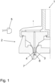
- FIG. 1 A first, in the Figures 1 and 2
- a fiber sliver is first drawn using a multi-roller drafting system and the drawn fiber sliver obtained is then fed to the air spinning nozzle 2 via a fiber sliver inlet 7.
- the fiber sliver is drawn after being introduced via the fiber sliver inlet 7 by a distance extending in the fiber sliver transport direction in a known manner in the direction of the yarn forming element 4 approximately to the outlet channel mouth of the same. Needle 8 is guided.
- needle 8 As an alternative to needle 8, according to a further preferred embodiment, a well-known pair of tweezers can be arranged.
- the outer fibers of the fiber band are wound around an inner fiber core by means of a vortex air flow generated by air spinnerets 2 in the region of an inlet opening of the air spinneret 2, so that an air yarn-specific yarn structure of a parallel yarn core and wrapped fibers lying at a certain angle results, which are crucial for the desired strength of the yarn.
- a cleaning nozzle 5 is arranged stationary outside the vortex chamber 3 in the area of the spinning station 1, whereby due to its arrangement this does not influence the air spinning process in the closed air spinning nozzle 2 (see Figure 1 ).
- the yarn forming element 4 is moved into a cleaning position when the air spinneret 2 is opened, in which an outlet opening of the stationary cleaning nozzle 5 is aligned with a side surface of the yarn forming element 4, so that the surface of the yarn forming element 4 can be cleaned by means of the cleaning nozzle 5 (see Figure 2 ).
- At least one aqueous cleaning liquid is atomized by means of the cleaning nozzle 5 and directed as a spray mist onto the yarn forming element 4, so that the deposits adhering to the surface of the yarn forming element 4 can be removed.
- a cleaning cycle is carried out by means of a cleaning cycle, which can be carried out either once or repeated several times.
- a first possible cleaning cycle provides that a cleaning liquid is first sprayed onto the surface of the yarn forming element 4 using the cleaning nozzle 5 to remove deposits and then also using the A compressed air pulse is directed onto the surface of the yarn forming element 4 via the cleaning nozzle 5 in order to remove the mixture of the cleaning liquid and the dissolved adhesions and to dry the surface of the yarn forming element 4.
- a foam is applied to the surface of the yarn forming element 4 via the cleaning nozzle 5, the foam being mixed with a non-stick liquid.
- the yarn forming element 4 with the non-stick liquid applied to it is dried by means of the subsequent compressed air pulse.
- a compressed air pulse is first directed at the surface of the yarn forming element 4 in order to remove loose adhesions. Cleaning is then carried out using a cleaning medium such as the cleaning liquid in order to remove the adhesions that have not been dissolved by the compressed air. Finally, the mixture of the cleaning liquid and the dissolved adhesions is preferably removed and the surface of the yarn forming element 4 is dried by applying compressed air again.
- the same cleaning nozzle 5 is preferably used for all cleaning steps.
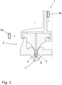
- a second, in the Figures 3 and 4 The illustrated embodiment of a spinning station 1 of an air spinning machine differs significantly from the first embodiment in that two movable cleaning nozzles 5a, b are provided instead of a stationary cleaning nozzle 5.
- a first cleaning nozzle 5a is arranged to be linearly displaceable in the direction of a side surface of the yarn-forming element 4, wherein this cleaning nozzle 5a is also linearly displaced into a cleaning position for cleaning the surface of the yarn-forming element 4 after opening the air spinneret 2, during which the yarn-forming element 4 is moved into a cleaning position, and thus at least one cleaning medium, in particular a cleaning liquid, an aerosol, a foam, an emulsion or a gas, can be applied to the yarn-forming element 4 in the immediate vicinity of the surface of the yarn-forming element 4.
- a cleaning medium in particular a cleaning liquid, an aerosol, a foam, an emulsion or a gas
- this cleaning nozzle 5a can also be at least partially wrapped around the Yarn-forming element 4 can be pivotably arranged so that a cleaning fluid can be applied along the circumference of the surface of yarn-forming element 4.
- the second cleaning nozzle 5b is both linearly movable and can be swivelled by means of a swivel device 6 (in Figure 4
- the first cleaning nozzle 5b is arranged so that it can pivot towards the surface of the yarn forming element 4 (only shown schematically by an arrow).
- the second cleaning nozzle 5b is already displaced linearly during the opening of the air spinning nozzle 2 and the associated positioning of the yarn forming element 4 in a cleaning position.
- the cleaning nozzle 5b is then pivoted towards the surface of the yarn forming element 4 by means of the pivoting device 6 so that cleaning can be carried out using both cleaning nozzles 5a, 5b.
- cleaning can be carried out with all cleaning nozzles 5 at the same time or the cleaning nozzles 5a, 5b can be used one after the other for cleaning.
- cleaning nozzles 5a, 5b can be used one after the other for cleaning.
Landscapes
- Engineering & Computer Science (AREA)
- Mechanical Engineering (AREA)
- Textile Engineering (AREA)
- Spinning Or Twisting Of Yarns (AREA)
Claims (12)
- Poste de filage (1) d'un métier à filer à jet d'air, comportant- une filière à jet d'air (2) comportant un élément de formation de fil (4) disposé à l'intérieur d'une chambre de turbulence (3) et destiné à produire un fil à partir d'une mèche de fibres amenée à la filière à jet d'air (2), dans lequel- la filière à jet d'air (2) peut passer d'un état fermé pour la formation de fil à un état ouvert dans lequel l'élément de formation de fil (4) peut être nettoyé,- une buse de nettoyage (5 ; 5a ; 5b) pour le nettoyage de l'élément de formation de fil (4) à l'état ouvert de la filière à jet d'air (2),caractérisé en ce que
la buse de nettoyage (5 ; 5a ; 5b) peut être déplacée par rapport à l'élément de formation de fil (4) au moyen d'un dispositif de pivotement (6), au moins entre une position de repos et une position de nettoyage pour le nettoyage de l'élément de formation de fil (4), et est conçue de manière à pouvoir être positionnée et/ou orientée de telle sorte qu'au moins dans l'état ouvert de la filière à jet d'air (2), l'élément de formation de fil (4) peut être alimenté frontalement et/ou latéralement avec un milieu de nettoyage dans la position de nettoyage, au moins sur une partie de sa surface. - Poste de filage (1) d'un métier à filer à jet d'air selon la revendication 1, caractérisé en ce qu'au moins une buse de nettoyage (5 ; 5a ; 5b) est disposée à l'extérieur de la chambre de turbulence (3) et/ou de manière stationnaire.
- Poste de filage (1) d'un métier à filer à jet d'air selon la revendication 2, caractérisé en ce que la buse de nettoyage (5a ; 5b) peut être mise en rotation, au moyen du dispositif de pivotement (6), au moins autour d'une partie du pourtour de l'élément de formation de fil (4).
- Poste de filage (1) selon la revendication 2 ou 3, caractérisé en ce que la buse de nettoyage (5a ; 5b) peut être déplacée par rapport à l'élément de formation de fil (4) au moyen du dispositif de pivotement (6), dans au moins deux directions différentes l'une de l'autre.
- Procédé permettant de nettoyer un élément de formation de fil (4) d'une filière à jet d'air comportant l'élément de formation de fil (4) disposé à l'intérieur d'une chambre de turbulence (3) et destiné à produire un fil à partir d'une mèche de fibres amenée à la filière à jet d'air (2), dans lequel la filière à jet d'air (2) peut être amenée d'un état fermé pour la formation de fil à un état ouvert dans lequel l'élément de formation de fil (4) peut être nettoyé, comportant les étapes consistant à :- ouvrir la filière à jet d'air (2) pour rendre accessible l'élément de formation de fil (4) disposé dans la chambre de turbulence (3),- déplacer une buse de nettoyage (5 ; 5a ; 5b) par rapport à l'élément de formation de fil (4) d'une position de repos à une position de nettoyage, pour le nettoyage de l'élément de formation de fil (4), au moyen d'un dispositif de pivotement (6) et, en particulier, déplacer l'élément de formation de fil (4) dans une position de nettoyage, et- alimenter l'élément de formation de fil (4) avec au moins un milieu de nettoyage dans la position de nettoyage, frontalement et/ou latéralement, au moins sur une partie de sa surface, au moyen de la buse de nettoyage (5 ; 5a ; 5b) positionnée et/ou orientée de manière appropriée à cet effet.
- Procédé selon la revendication 5, caractérisé en ce que le déplacement de l'élément de formation de fil (4) et/ou de la buse de nettoyage (5 ; 5a ; 5b) dans la position de nettoyage est effectué par un déclenchement du processus d'ouverture de la filière à jet d'air (2), pendant l'ouverture de la filière à jet d'air (2) et/ou après l'ouverture de la filière à jet d'air (2).
- Procédé selon au moins l'une des revendications 5 ou 6, caractérisé en ce que le déplacement de l'élément de formation de fil (4) est effectué de telle sorte que la buse de nettoyage (5 ; 5a ; 5b) se trouve dans la position de nettoyage à la fin du processus d'ouverture.
- Procédé selon au moins l'une des revendications 5 à 7, caractérisé en ce qu'un nettoyage de l'élément de formation de fil (4) est effectué à la suite d'une rupture de filage, par exemple après au moins une rupture de fil, après au moins une coupe du fil, pendant un prélèvement d'une bobine d'enroulement bobinée au moyen du fil filé à l'air et/ou pendant un changement d'un pot de filage.
- Procédé selon au moins l'une des revendications 5 à 8, caractérisé en ce qu'un liquide de nettoyage aqueux, un aérosol, une mousse, une émulsion ou un gaz est utilisé comme milieu de nettoyage.
- Procédé selon au moins l'une des revendications 5 à 9, caractérisé en ce que soit un nettoyage au moyen d'un liquide de nettoyage, d'un aérosol, d'une mousse ou d'une émulsion suit une seconde étape de nettoyage où l'élément de formation de fil (4) est alimenté avec un flux de gaz, soit un nettoyage au moyen d'un flux de gaz suit une seconde étape de nettoyage où l'élément de formation de fil (4) est alimenté avec un liquide de nettoyage, un aérosol, une mousse ou une émulsion, par l'intermédiaire de la buse de nettoyage (5).
- Procédé selon au moins l'une des revendications 5 à 10, caractérisé en ce qu'un nettoyage de l'élément de formation de fil (4) est effectué d'abord au moyen d'un premier flux de gaz pour éliminer les particules détachées de l'élément de formation de fil (4), ensuite au moyen d'un liquide de nettoyage, d'un aérosol, d'une mousse ou d'une émulsion pour détacher les particules adhérentes et par la suite au moyen d'un second flux de gaz pour le nettoyage et le séchage finaux de l'élément de formation de fil (4).
- Procédé selon l'une des revendications 10 ou 11, caractérisé en ce que le nettoyage est effectué au moyen du liquide de nettoyage, de l'aérosol, de la mousse ou de l'émulsion et au moyen du flux de gaz ou du premier et/ou du second flux de gaz, au moyen de la même buse de nettoyage (5 ; 5a ; 5b).
Priority Applications (5)
| Application Number | Priority Date | Filing Date | Title |
|---|---|---|---|
| EP20215332.6A EP4015681B1 (fr) | 2020-12-18 | 2020-12-18 | Poste de filage doté d'une buse de nettoyage et procédé de nettoyage d'un élément de formation de fil |
| US17/554,174 US11834759B2 (en) | 2020-12-18 | 2021-12-17 | Spinning position with a cleaning nozzle and method of cleaning a yarn forming element |
| BR102021025617-6A BR102021025617A2 (pt) | 2020-12-18 | 2021-12-17 | Posto de fiação com um bico de limpeza e método para a limpeza de um elemento de formação de fio |
| CN202111550502.8A CN114645345A (zh) | 2020-12-18 | 2021-12-17 | 具有清洁喷嘴的纺纱位置和用于清洁纱线形成件的方法 |
| JP2021205367A JP7853753B2 (ja) | 2020-12-18 | 2021-12-17 | クリーニングノズルを備えた紡績ユニットおよび糸形成エレメントをクリーニングする方法 |
Applications Claiming Priority (1)
| Application Number | Priority Date | Filing Date | Title |
|---|---|---|---|
| EP20215332.6A EP4015681B1 (fr) | 2020-12-18 | 2020-12-18 | Poste de filage doté d'une buse de nettoyage et procédé de nettoyage d'un élément de formation de fil |
Publications (2)
| Publication Number | Publication Date |
|---|---|
| EP4015681A1 EP4015681A1 (fr) | 2022-06-22 |
| EP4015681B1 true EP4015681B1 (fr) | 2025-01-29 |
Family
ID=73855702
Family Applications (1)
| Application Number | Title | Priority Date | Filing Date |
|---|---|---|---|
| EP20215332.6A Active EP4015681B1 (fr) | 2020-12-18 | 2020-12-18 | Poste de filage doté d'une buse de nettoyage et procédé de nettoyage d'un élément de formation de fil |
Country Status (5)
| Country | Link |
|---|---|
| US (1) | US11834759B2 (fr) |
| EP (1) | EP4015681B1 (fr) |
| JP (1) | JP7853753B2 (fr) |
| CN (1) | CN114645345A (fr) |
| BR (1) | BR102021025617A2 (fr) |
Families Citing this family (5)
| Publication number | Priority date | Publication date | Assignee | Title |
|---|---|---|---|---|
| EP4012083A1 (fr) * | 2020-12-09 | 2022-06-15 | Saurer Intelligent Technology AG | Élément à filer d'une filière à jet d'air pour un métier à filer à jet d'air |
| DE102020133359A1 (de) | 2020-12-14 | 2022-06-15 | Saurer Spinning Solutions Gmbh & Co. Kg | Multifunktionsdüse für eine Spinnmaschine |
| EP4015681B1 (fr) | 2020-12-18 | 2025-01-29 | Saurer Intelligent Technology AG | Poste de filage doté d'une buse de nettoyage et procédé de nettoyage d'un élément de formation de fil |
| DE102022114064A1 (de) | 2022-06-03 | 2023-12-14 | Saurer Spinning Solutions Gmbh & Co. Kg | Fadenabzugsdüse sowie Offenend-Spinnvorrichtung mit einer Fadenabzugsdüse |
| CN115156169B (zh) * | 2022-07-06 | 2023-07-28 | 杭州临港化纤有限公司 | 一种假捻盘的清洗工艺 |
Family Cites Families (18)
| Publication number | Priority date | Publication date | Assignee | Title |
|---|---|---|---|---|
| US4107911A (en) * | 1976-06-18 | 1978-08-22 | Murata Kikai Kabushiki Kaisha | Pneumatic spinning apparatus |
| JPS5932606Y2 (ja) * | 1981-10-13 | 1984-09-12 | 村田機械株式会社 | 空気式紡績装置における空気ノズル先端部の空気の整流板 |
| CH683697A5 (de) * | 1990-07-20 | 1994-04-29 | Rieter Ag Maschf | Vorrichtung zum automatischen Ansetzen oder Anspinnen eines Fadens und Verfahren zu ihrem Betrieb. |
| US5177950A (en) * | 1990-12-06 | 1993-01-12 | Fowler Jr Floyd N | Flexible whirl-cleaning nozzle |
| JPH0625923A (ja) * | 1992-04-30 | 1994-02-01 | Murata Mach Ltd | 風綿清掃台車 |
| EP0646192B1 (fr) * | 1993-04-16 | 1996-11-13 | Luwa AG | Installation permettant d'influer sur les conditions d'environnement de processus de traitement textiles |
| JP2009155749A (ja) | 2007-12-26 | 2009-07-16 | Murata Mach Ltd | 紡績機 |
| JP2011038210A (ja) * | 2009-08-11 | 2011-02-24 | Murata Machinery Ltd | 空気紡績装置及びこの空気紡績装置を備える紡績機 |
| DE102012100674A1 (de) * | 2012-01-27 | 2013-08-01 | Maschinenfabrik Rieter Ag | Luftspinnmaschine mit einem Reinigungsorgan sowie Verfahren zum Reinigen der Wirbelkammer einer Luftspinnmaschine |
| JP2015101805A (ja) * | 2013-11-25 | 2015-06-04 | 村田機械株式会社 | 空気紡績装置及び紡績機 |
| CH709466A1 (de) | 2014-04-03 | 2015-10-15 | Rieter Ag Maschf | Spinnstelle einer Luftspinnmaschine sowie Verfahren zum Betrieb einer Luftspinnmaschine. |
| CH709749A1 (de) * | 2014-06-12 | 2015-12-15 | Rieter Ag Maschf | Luftspinnmaschine sowie Verfahren zum Betrieb einer solchen. |
| DE102015100825A1 (de) | 2015-01-21 | 2016-07-21 | Maschinenfabrik Rieter Ag | Spinndüse einer Luftspinnmaschine sowie Verfahren zum Öffnen derselben |
| CH713499A2 (de) * | 2017-02-28 | 2018-08-31 | Rieter Ag Maschf | Luftspinnmaschine zur Herstellung eines Garns aus einem strangförmigen Faserverband. |
| DE102017113257A1 (de) * | 2017-06-16 | 2018-12-20 | Maschinenfabrik Rieter Ag | Arbeitsstelle einer Luftspinnmaschine sowie Verfahren zum Öffnen einer Spinndüse |
| JP2019026980A (ja) * | 2017-08-02 | 2019-02-21 | 村田機械株式会社 | 空気紡績機 |
| DE102018130826A1 (de) * | 2018-12-04 | 2020-06-04 | Maschinenfabrik Rieter Ag | Spinndüse sowie Verfahren zum Reinigen derselben |
| EP4015681B1 (fr) | 2020-12-18 | 2025-01-29 | Saurer Intelligent Technology AG | Poste de filage doté d'une buse de nettoyage et procédé de nettoyage d'un élément de formation de fil |
-
2020
- 2020-12-18 EP EP20215332.6A patent/EP4015681B1/fr active Active
-
2021
- 2021-12-17 US US17/554,174 patent/US11834759B2/en active Active
- 2021-12-17 BR BR102021025617-6A patent/BR102021025617A2/pt not_active Application Discontinuation
- 2021-12-17 JP JP2021205367A patent/JP7853753B2/ja active Active
- 2021-12-17 CN CN202111550502.8A patent/CN114645345A/zh active Pending
Also Published As
| Publication number | Publication date |
|---|---|
| BR102021025617A2 (pt) | 2022-06-28 |
| JP2022097468A (ja) | 2022-06-30 |
| US11834759B2 (en) | 2023-12-05 |
| CN114645345A (zh) | 2022-06-21 |
| JP7853753B2 (ja) | 2026-04-30 |
| US20220195634A1 (en) | 2022-06-23 |
| EP4015681A1 (fr) | 2022-06-22 |
Similar Documents
| Publication | Publication Date | Title |
|---|---|---|
| EP4015681A1 (fr) | Poste de filage doté d'une buse de nettoyage et procédé de nettoyage d'un élément de formation de fil | |
| DE19501545C2 (de) | Verfahren zum Andrehen eines Garnes in einer Spinnmaschine | |
| EP2767625B1 (fr) | Poste de filage d'un métier à filer | |
| EP2767624B1 (fr) | Poste de filage d'un métier à tisser à jet d'air | |
| EP2980285B1 (fr) | Poste de filage d'une machine de filage à jet d'air et utilisation de celle-ci | |
| EP2955256B1 (fr) | Metier a filer a jet d'air et procede de fonctionnement d'un tel metier a filer a jet d'air | |
| EP2944713B1 (fr) | Poste de filage pour une machine de filage à jet d'air et utilisation de celle-ci | |
| EP3148913A1 (fr) | Procédé permettant de faire fonctionner une machine textile et machine textile servant à produire une mèche | |
| EP3276057A1 (fr) | Unité guide-fil, métier à tisser à extrémité ouverte et procédé de fonctionnement d'un poste de filage | |
| WO2008095631A1 (fr) | Dispositif de filage à air | |
| CH628095A5 (de) | Verfahren zum direkten spinnen eines garnes aus einem faserband, und vorrichtung zur durchfuehrung des verfahrens. | |
| DE10053073A1 (de) | Spinnvorrichtung | |
| EP0162367B1 (fr) | Procédé et dispositif pour la préparation de l'extrémité de fil pour la remise en route d'une machine à bout libéré | |
| DE4305052A1 (en) | Spinning assembly to apply air stream to a sliver - has a porous suction roller at leading end of the drawing unit to take up fibre waste from the pneumatic spinning appts. | |
| EP1280946A1 (fr) | Procede et dispositif pour acheminer sans traction des corps moules continus | |
| EP4015680B1 (fr) | Poste de filage d'un métier à filer à jet d'air et procédé de nettoyage d'un élément de formation de fil | |
| DE3430369A1 (de) | Verfahren und vorrichtung zur herstellung eines verbaenderten gesponnenen garnes | |
| EP3839114B1 (fr) | Procédé d'agencement d'une bande de fibre sur une unité de filage d'un métier à filer | |
| CH707560A1 (de) | Spinnstelle einer Luftdüsenspinnmaschine. | |
| EP4239113B1 (fr) | Dispositif de filage à jet d'air et procédé de traitement de surface dans un dispositif de filage à jet d'air | |
| DE10133152A1 (de) | Rotorspinnmaschine | |
| LU102753B1 (de) | Faserband-Streckwerk mit Additivzuführung | |
| DE4311272A1 (de) | Vorrichtung zur Reduzierung der Haarigkeit von Fasergarnen am laufenden Faden | |
| EP1377515B1 (fr) | Procede et dispositif pour humidifier un fil | |
| DE10220508A1 (de) | Verfahren und Vorrichtung zur Behandlung eines Fadens |
Legal Events
| Date | Code | Title | Description |
|---|---|---|---|
| PUAI | Public reference made under article 153(3) epc to a published international application that has entered the european phase |
Free format text: ORIGINAL CODE: 0009012 |
|
| STAA | Information on the status of an ep patent application or granted ep patent |
Free format text: STATUS: THE APPLICATION HAS BEEN PUBLISHED |
|
| AK | Designated contracting states |
Kind code of ref document: A1 Designated state(s): AL AT BE BG CH CY CZ DE DK EE ES FI FR GB GR HR HU IE IS IT LI LT LU LV MC MK MT NL NO PL PT RO RS SE SI SK SM TR |
|
| STAA | Information on the status of an ep patent application or granted ep patent |
Free format text: STATUS: REQUEST FOR EXAMINATION WAS MADE |
|
| 17P | Request for examination filed |
Effective date: 20221222 |
|
| RBV | Designated contracting states (corrected) |
Designated state(s): AL AT BE BG CH CY CZ DE DK EE ES FI FR GB GR HR HU IE IS IT LI LT LU LV MC MK MT NL NO PL PT RO RS SE SI SK SM TR |
|
| GRAP | Despatch of communication of intention to grant a patent |
Free format text: ORIGINAL CODE: EPIDOSNIGR1 |
|
| STAA | Information on the status of an ep patent application or granted ep patent |
Free format text: STATUS: GRANT OF PATENT IS INTENDED |
|
| INTG | Intention to grant announced |
Effective date: 20240816 |
|
| GRAS | Grant fee paid |
Free format text: ORIGINAL CODE: EPIDOSNIGR3 |
|
| GRAA | (expected) grant |
Free format text: ORIGINAL CODE: 0009210 |
|
| STAA | Information on the status of an ep patent application or granted ep patent |
Free format text: STATUS: THE PATENT HAS BEEN GRANTED |
|
| RAP1 | Party data changed (applicant data changed or rights of an application transferred) |
Owner name: SAURER INTELLIGENT TECHNOLOGY AG |
|
| AK | Designated contracting states |
Kind code of ref document: B1 Designated state(s): AL AT BE BG CH CY CZ DE DK EE ES FI FR GB GR HR HU IE IS IT LI LT LU LV MC MK MT NL NO PL PT RO RS SE SI SK SM TR |
|
| REG | Reference to a national code |
Ref country code: GB Ref legal event code: FG4D Free format text: NOT ENGLISH |
|
| REG | Reference to a national code |
Ref country code: CH Ref legal event code: EP |
|
| REG | Reference to a national code |
Ref country code: DE Ref legal event code: R096 Ref document number: 502020010312 Country of ref document: DE |
|
| REG | Reference to a national code |
Ref country code: IE Ref legal event code: FG4D Free format text: LANGUAGE OF EP DOCUMENT: GERMAN |
|
| REG | Reference to a national code |
Ref country code: NL Ref legal event code: MP Effective date: 20250129 |
|
| PG25 | Lapsed in a contracting state [announced via postgrant information from national office to epo] |
Ref country code: NL Free format text: LAPSE BECAUSE OF FAILURE TO SUBMIT A TRANSLATION OF THE DESCRIPTION OR TO PAY THE FEE WITHIN THE PRESCRIBED TIME-LIMIT Effective date: 20250129 |
|
| PG25 | Lapsed in a contracting state [announced via postgrant information from national office to epo] |
Ref country code: RS Free format text: LAPSE BECAUSE OF FAILURE TO SUBMIT A TRANSLATION OF THE DESCRIPTION OR TO PAY THE FEE WITHIN THE PRESCRIBED TIME-LIMIT Effective date: 20250429 |
|
| PG25 | Lapsed in a contracting state [announced via postgrant information from national office to epo] |
Ref country code: FI Free format text: LAPSE BECAUSE OF FAILURE TO SUBMIT A TRANSLATION OF THE DESCRIPTION OR TO PAY THE FEE WITHIN THE PRESCRIBED TIME-LIMIT Effective date: 20250129 |
|
| PG25 | Lapsed in a contracting state [announced via postgrant information from national office to epo] |
Ref country code: PL Free format text: LAPSE BECAUSE OF FAILURE TO SUBMIT A TRANSLATION OF THE DESCRIPTION OR TO PAY THE FEE WITHIN THE PRESCRIBED TIME-LIMIT Effective date: 20250129 |
|
| PG25 | Lapsed in a contracting state [announced via postgrant information from national office to epo] |
Ref country code: ES Free format text: LAPSE BECAUSE OF FAILURE TO SUBMIT A TRANSLATION OF THE DESCRIPTION OR TO PAY THE FEE WITHIN THE PRESCRIBED TIME-LIMIT Effective date: 20250129 |
|
| REG | Reference to a national code |
Ref country code: LT Ref legal event code: MG9D |
|
| PG25 | Lapsed in a contracting state [announced via postgrant information from national office to epo] |
Ref country code: NO Free format text: LAPSE BECAUSE OF FAILURE TO SUBMIT A TRANSLATION OF THE DESCRIPTION OR TO PAY THE FEE WITHIN THE PRESCRIBED TIME-LIMIT Effective date: 20250429 Ref country code: IS Free format text: LAPSE BECAUSE OF FAILURE TO SUBMIT A TRANSLATION OF THE DESCRIPTION OR TO PAY THE FEE WITHIN THE PRESCRIBED TIME-LIMIT Effective date: 20250529 |
|
| PG25 | Lapsed in a contracting state [announced via postgrant information from national office to epo] |
Ref country code: HR Free format text: LAPSE BECAUSE OF FAILURE TO SUBMIT A TRANSLATION OF THE DESCRIPTION OR TO PAY THE FEE WITHIN THE PRESCRIBED TIME-LIMIT Effective date: 20250129 |
|
| PG25 | Lapsed in a contracting state [announced via postgrant information from national office to epo] |
Ref country code: LV Free format text: LAPSE BECAUSE OF FAILURE TO SUBMIT A TRANSLATION OF THE DESCRIPTION OR TO PAY THE FEE WITHIN THE PRESCRIBED TIME-LIMIT Effective date: 20250129 Ref country code: PT Free format text: LAPSE BECAUSE OF FAILURE TO SUBMIT A TRANSLATION OF THE DESCRIPTION OR TO PAY THE FEE WITHIN THE PRESCRIBED TIME-LIMIT Effective date: 20250529 |
|
| PG25 | Lapsed in a contracting state [announced via postgrant information from national office to epo] |
Ref country code: BG Free format text: LAPSE BECAUSE OF FAILURE TO SUBMIT A TRANSLATION OF THE DESCRIPTION OR TO PAY THE FEE WITHIN THE PRESCRIBED TIME-LIMIT Effective date: 20250129 Ref country code: GR Free format text: LAPSE BECAUSE OF FAILURE TO SUBMIT A TRANSLATION OF THE DESCRIPTION OR TO PAY THE FEE WITHIN THE PRESCRIBED TIME-LIMIT Effective date: 20250430 |
|
| PG25 | Lapsed in a contracting state [announced via postgrant information from national office to epo] |
Ref country code: SE Free format text: LAPSE BECAUSE OF FAILURE TO SUBMIT A TRANSLATION OF THE DESCRIPTION OR TO PAY THE FEE WITHIN THE PRESCRIBED TIME-LIMIT Effective date: 20250129 |
|
| PG25 | Lapsed in a contracting state [announced via postgrant information from national office to epo] |
Ref country code: SM Free format text: LAPSE BECAUSE OF FAILURE TO SUBMIT A TRANSLATION OF THE DESCRIPTION OR TO PAY THE FEE WITHIN THE PRESCRIBED TIME-LIMIT Effective date: 20250129 |
|
| PG25 | Lapsed in a contracting state [announced via postgrant information from national office to epo] |
Ref country code: DK Free format text: LAPSE BECAUSE OF FAILURE TO SUBMIT A TRANSLATION OF THE DESCRIPTION OR TO PAY THE FEE WITHIN THE PRESCRIBED TIME-LIMIT Effective date: 20250129 |
|
| PG25 | Lapsed in a contracting state [announced via postgrant information from national office to epo] |
Ref country code: EE Free format text: LAPSE BECAUSE OF FAILURE TO SUBMIT A TRANSLATION OF THE DESCRIPTION OR TO PAY THE FEE WITHIN THE PRESCRIBED TIME-LIMIT Effective date: 20250129 |
|
| PG25 | Lapsed in a contracting state [announced via postgrant information from national office to epo] |
Ref country code: RO Free format text: LAPSE BECAUSE OF FAILURE TO SUBMIT A TRANSLATION OF THE DESCRIPTION OR TO PAY THE FEE WITHIN THE PRESCRIBED TIME-LIMIT Effective date: 20250129 |
|
| PG25 | Lapsed in a contracting state [announced via postgrant information from national office to epo] |
Ref country code: SK Free format text: LAPSE BECAUSE OF FAILURE TO SUBMIT A TRANSLATION OF THE DESCRIPTION OR TO PAY THE FEE WITHIN THE PRESCRIBED TIME-LIMIT Effective date: 20250129 |
|
| REG | Reference to a national code |
Ref country code: DE Ref legal event code: R097 Ref document number: 502020010312 Country of ref document: DE |
|
| PLBE | No opposition filed within time limit |
Free format text: ORIGINAL CODE: 0009261 |
|
| STAA | Information on the status of an ep patent application or granted ep patent |
Free format text: STATUS: NO OPPOSITION FILED WITHIN TIME LIMIT |
|
| REG | Reference to a national code |
Ref country code: CH Ref legal event code: L10 Free format text: ST27 STATUS EVENT CODE: U-0-0-L10-L00 (AS PROVIDED BY THE NATIONAL OFFICE) Effective date: 20251210 |
|
| REG | Reference to a national code |
Ref country code: CH Ref legal event code: U11 Free format text: ST27 STATUS EVENT CODE: U-0-0-U10-U11 (AS PROVIDED BY THE NATIONAL OFFICE) Effective date: 20260101 |
|
| 26N | No opposition filed |
Effective date: 20251030 |
|
| PGFP | Annual fee paid to national office [announced via postgrant information from national office to epo] |
Ref country code: CZ Payment date: 20251205 Year of fee payment: 6 |
|
| PGFP | Annual fee paid to national office [announced via postgrant information from national office to epo] |
Ref country code: DE Payment date: 20251222 Year of fee payment: 6 |
|
| PGFP | Annual fee paid to national office [announced via postgrant information from national office to epo] |
Ref country code: IT Payment date: 20251231 Year of fee payment: 6 |
|
| PGFP | Annual fee paid to national office [announced via postgrant information from national office to epo] |
Ref country code: CH Payment date: 20260101 Year of fee payment: 6 |