EP3663471A1 - Procédé de fabrication d'un tuyau, tuyau et élément de raccordement pour un tuyau - Google Patents
Procédé de fabrication d'un tuyau, tuyau et élément de raccordement pour un tuyau Download PDFInfo
- Publication number
- EP3663471A1 EP3663471A1 EP19214062.2A EP19214062A EP3663471A1 EP 3663471 A1 EP3663471 A1 EP 3663471A1 EP 19214062 A EP19214062 A EP 19214062A EP 3663471 A1 EP3663471 A1 EP 3663471A1
- Authority
- EP
- European Patent Office
- Prior art keywords
- hose
- section
- hose section
- joining
- connection piece
- Prior art date
- Legal status (The legal status is an assumption and is not a legal conclusion. Google has not performed a legal analysis and makes no representation as to the accuracy of the status listed.)
- Granted
Links
Images


Classifications
-
- F—MECHANICAL ENGINEERING; LIGHTING; HEATING; WEAPONS; BLASTING
- F16—ENGINEERING ELEMENTS AND UNITS; GENERAL MEASURES FOR PRODUCING AND MAINTAINING EFFECTIVE FUNCTIONING OF MACHINES OR INSTALLATIONS; THERMAL INSULATION IN GENERAL
- F16L—PIPES; JOINTS OR FITTINGS FOR PIPES; SUPPORTS FOR PIPES, CABLES OR PROTECTIVE TUBING; MEANS FOR THERMAL INSULATION IN GENERAL
- F16L11/00—Hoses, i.e. flexible pipes
- F16L11/14—Hoses, i.e. flexible pipes made of rigid material, e.g. metal or hard plastics
- F16L11/15—Hoses, i.e. flexible pipes made of rigid material, e.g. metal or hard plastics corrugated
-
- B—PERFORMING OPERATIONS; TRANSPORTING
- B29—WORKING OF PLASTICS; WORKING OF SUBSTANCES IN A PLASTIC STATE IN GENERAL
- B29C—SHAPING OR JOINING OF PLASTICS; SHAPING OF MATERIAL IN A PLASTIC STATE, NOT OTHERWISE PROVIDED FOR; AFTER-TREATMENT OF THE SHAPED PRODUCTS, e.g. REPAIRING
- B29C48/00—Extrusion moulding, i.e. expressing the moulding material through a die or nozzle which imparts the desired form; Apparatus therefor
- B29C48/03—Extrusion moulding, i.e. expressing the moulding material through a die or nozzle which imparts the desired form; Apparatus therefor characterised by the shape of the extruded material at extrusion
- B29C48/09—Articles with cross-sections having partially or fully enclosed cavities, e.g. pipes or channels
-
- B—PERFORMING OPERATIONS; TRANSPORTING
- B29—WORKING OF PLASTICS; WORKING OF SUBSTANCES IN A PLASTIC STATE IN GENERAL
- B29C—SHAPING OR JOINING OF PLASTICS; SHAPING OF MATERIAL IN A PLASTIC STATE, NOT OTHERWISE PROVIDED FOR; AFTER-TREATMENT OF THE SHAPED PRODUCTS, e.g. REPAIRING
- B29C48/00—Extrusion moulding, i.e. expressing the moulding material through a die or nozzle which imparts the desired form; Apparatus therefor
- B29C48/03—Extrusion moulding, i.e. expressing the moulding material through a die or nozzle which imparts the desired form; Apparatus therefor characterised by the shape of the extruded material at extrusion
- B29C48/13—Articles with a cross-section varying in the longitudinal direction, e.g. corrugated pipes
-
- B—PERFORMING OPERATIONS; TRANSPORTING
- B29—WORKING OF PLASTICS; WORKING OF SUBSTANCES IN A PLASTIC STATE IN GENERAL
- B29C—SHAPING OR JOINING OF PLASTICS; SHAPING OF MATERIAL IN A PLASTIC STATE, NOT OTHERWISE PROVIDED FOR; AFTER-TREATMENT OF THE SHAPED PRODUCTS, e.g. REPAIRING
- B29C65/00—Joining or sealing of preformed parts, e.g. welding of plastics materials; Apparatus therefor
- B29C65/02—Joining or sealing of preformed parts, e.g. welding of plastics materials; Apparatus therefor by heating, with or without pressure
-
- B—PERFORMING OPERATIONS; TRANSPORTING
- B29—WORKING OF PLASTICS; WORKING OF SUBSTANCES IN A PLASTIC STATE IN GENERAL
- B29C—SHAPING OR JOINING OF PLASTICS; SHAPING OF MATERIAL IN A PLASTIC STATE, NOT OTHERWISE PROVIDED FOR; AFTER-TREATMENT OF THE SHAPED PRODUCTS, e.g. REPAIRING
- B29C66/00—General aspects of processes or apparatus for joining preformed parts
- B29C66/01—General aspects dealing with the joint area or with the area to be joined
- B29C66/05—Particular design of joint configurations
- B29C66/10—Particular design of joint configurations particular design of the joint cross-sections
- B29C66/12—Joint cross-sections combining only two joint-segments; Tongue and groove joints; Tenon and mortise joints; Stepped joint cross-sections
- B29C66/124—Tongue and groove joints
- B29C66/1244—Tongue and groove joints characterised by the male part, i.e. the part comprising the tongue
- B29C66/12441—Tongue and groove joints characterised by the male part, i.e. the part comprising the tongue being a single wall
-
- B—PERFORMING OPERATIONS; TRANSPORTING
- B29—WORKING OF PLASTICS; WORKING OF SUBSTANCES IN A PLASTIC STATE IN GENERAL
- B29C—SHAPING OR JOINING OF PLASTICS; SHAPING OF MATERIAL IN A PLASTIC STATE, NOT OTHERWISE PROVIDED FOR; AFTER-TREATMENT OF THE SHAPED PRODUCTS, e.g. REPAIRING
- B29C66/00—General aspects of processes or apparatus for joining preformed parts
- B29C66/01—General aspects dealing with the joint area or with the area to be joined
- B29C66/05—Particular design of joint configurations
- B29C66/10—Particular design of joint configurations particular design of the joint cross-sections
- B29C66/12—Joint cross-sections combining only two joint-segments; Tongue and groove joints; Tenon and mortise joints; Stepped joint cross-sections
- B29C66/124—Tongue and groove joints
- B29C66/1246—Tongue and groove joints characterised by the female part, i.e. the part comprising the groove
- B29C66/12469—Tongue and groove joints characterised by the female part, i.e. the part comprising the groove being asymmetric
-
- B—PERFORMING OPERATIONS; TRANSPORTING
- B29—WORKING OF PLASTICS; WORKING OF SUBSTANCES IN A PLASTIC STATE IN GENERAL
- B29C—SHAPING OR JOINING OF PLASTICS; SHAPING OF MATERIAL IN A PLASTIC STATE, NOT OTHERWISE PROVIDED FOR; AFTER-TREATMENT OF THE SHAPED PRODUCTS, e.g. REPAIRING
- B29C66/00—General aspects of processes or apparatus for joining preformed parts
- B29C66/50—General aspects of joining tubular articles; General aspects of joining long products, i.e. bars or profiled elements; General aspects of joining single elements to tubular articles, hollow articles or bars; General aspects of joining several hollow-preforms to form hollow or tubular articles
- B29C66/51—Joining tubular articles, profiled elements or bars; Joining single elements to tubular articles, hollow articles or bars; Joining several hollow-preforms to form hollow or tubular articles
- B29C66/53—Joining single elements to tubular articles, hollow articles or bars
- B29C66/534—Joining single elements to open ends of tubular or hollow articles or to the ends of bars
- B29C66/5344—Joining single elements to open ends of tubular or hollow articles or to the ends of bars said single elements being substantially annular, i.e. of finite length, e.g. joining flanges to tube ends
-
- B—PERFORMING OPERATIONS; TRANSPORTING
- B29—WORKING OF PLASTICS; WORKING OF SUBSTANCES IN A PLASTIC STATE IN GENERAL
- B29C—SHAPING OR JOINING OF PLASTICS; SHAPING OF MATERIAL IN A PLASTIC STATE, NOT OTHERWISE PROVIDED FOR; AFTER-TREATMENT OF THE SHAPED PRODUCTS, e.g. REPAIRING
- B29C66/00—General aspects of processes or apparatus for joining preformed parts
- B29C66/70—General aspects of processes or apparatus for joining preformed parts characterised by the composition, physical properties or the structure of the material of the parts to be joined; Joining with non-plastics material
- B29C66/73—General aspects of processes or apparatus for joining preformed parts characterised by the composition, physical properties or the structure of the material of the parts to be joined; Joining with non-plastics material characterised by the intensive physical properties of the material of the parts to be joined, by the optical properties of the material of the parts to be joined, by the extensive physical properties of the parts to be joined, by the state of the material of the parts to be joined or by the material of the parts to be joined being a thermoplastic or a thermoset
- B29C66/739—General aspects of processes or apparatus for joining preformed parts characterised by the composition, physical properties or the structure of the material of the parts to be joined; Joining with non-plastics material characterised by the intensive physical properties of the material of the parts to be joined, by the optical properties of the material of the parts to be joined, by the extensive physical properties of the parts to be joined, by the state of the material of the parts to be joined or by the material of the parts to be joined being a thermoplastic or a thermoset characterised by the material of the parts to be joined being a thermoplastic or a thermoset
- B29C66/7392—General aspects of processes or apparatus for joining preformed parts characterised by the composition, physical properties or the structure of the material of the parts to be joined; Joining with non-plastics material characterised by the intensive physical properties of the material of the parts to be joined, by the optical properties of the material of the parts to be joined, by the extensive physical properties of the parts to be joined, by the state of the material of the parts to be joined or by the material of the parts to be joined being a thermoplastic or a thermoset characterised by the material of the parts to be joined being a thermoplastic or a thermoset characterised by the material of at least one of the parts being a thermoplastic
- B29C66/73921—General aspects of processes or apparatus for joining preformed parts characterised by the composition, physical properties or the structure of the material of the parts to be joined; Joining with non-plastics material characterised by the intensive physical properties of the material of the parts to be joined, by the optical properties of the material of the parts to be joined, by the extensive physical properties of the parts to be joined, by the state of the material of the parts to be joined or by the material of the parts to be joined being a thermoplastic or a thermoset characterised by the material of the parts to be joined being a thermoplastic or a thermoset characterised by the material of at least one of the parts being a thermoplastic characterised by the materials of both parts being thermoplastics
-
- E—FIXED CONSTRUCTIONS
- E03—WATER SUPPLY; SEWERAGE
- E03C—DOMESTIC PLUMBING INSTALLATIONS FOR FRESH WATER OR WASTE WATER; SINKS
- E03C1/00—Domestic plumbing installations for fresh water or waste water; Sinks
- E03C1/02—Plumbing installations for fresh water
- E03C1/025—Water supply lines as such, e.g. shower hoses
-
- F—MECHANICAL ENGINEERING; LIGHTING; HEATING; WEAPONS; BLASTING
- F16—ENGINEERING ELEMENTS AND UNITS; GENERAL MEASURES FOR PRODUCING AND MAINTAINING EFFECTIVE FUNCTIONING OF MACHINES OR INSTALLATIONS; THERMAL INSULATION IN GENERAL
- F16L—PIPES; JOINTS OR FITTINGS FOR PIPES; SUPPORTS FOR PIPES, CABLES OR PROTECTIVE TUBING; MEANS FOR THERMAL INSULATION IN GENERAL
- F16L25/00—Construction or details of pipe joints not provided for in, or of interest apart from, groups F16L13/00 - F16L23/00
- F16L25/0036—Joints for corrugated pipes
-
- F—MECHANICAL ENGINEERING; LIGHTING; HEATING; WEAPONS; BLASTING
- F16—ENGINEERING ELEMENTS AND UNITS; GENERAL MEASURES FOR PRODUCING AND MAINTAINING EFFECTIVE FUNCTIONING OF MACHINES OR INSTALLATIONS; THERMAL INSULATION IN GENERAL
- F16L—PIPES; JOINTS OR FITTINGS FOR PIPES; SUPPORTS FOR PIPES, CABLES OR PROTECTIVE TUBING; MEANS FOR THERMAL INSULATION IN GENERAL
- F16L33/00—Arrangements for connecting hoses to rigid members; Rigid hose-connectors, i.e. single members engaging both hoses
- F16L33/006—Arrangements for connecting hoses to rigid members; Rigid hose-connectors, i.e. single members engaging both hoses for hoses of plastics other than artificial rubber
-
- F—MECHANICAL ENGINEERING; LIGHTING; HEATING; WEAPONS; BLASTING
- F16—ENGINEERING ELEMENTS AND UNITS; GENERAL MEASURES FOR PRODUCING AND MAINTAINING EFFECTIVE FUNCTIONING OF MACHINES OR INSTALLATIONS; THERMAL INSULATION IN GENERAL
- F16L—PIPES; JOINTS OR FITTINGS FOR PIPES; SUPPORTS FOR PIPES, CABLES OR PROTECTIVE TUBING; MEANS FOR THERMAL INSULATION IN GENERAL
- F16L47/00—Connecting arrangements or other fittings specially adapted to be made of plastics or to be used with pipes made of plastics
- F16L47/02—Welded joints; Adhesive joints
-
- F—MECHANICAL ENGINEERING; LIGHTING; HEATING; WEAPONS; BLASTING
- F16—ENGINEERING ELEMENTS AND UNITS; GENERAL MEASURES FOR PRODUCING AND MAINTAINING EFFECTIVE FUNCTIONING OF MACHINES OR INSTALLATIONS; THERMAL INSULATION IN GENERAL
- F16L—PIPES; JOINTS OR FITTINGS FOR PIPES; SUPPORTS FOR PIPES, CABLES OR PROTECTIVE TUBING; MEANS FOR THERMAL INSULATION IN GENERAL
- F16L47/00—Connecting arrangements or other fittings specially adapted to be made of plastics or to be used with pipes made of plastics
- F16L47/04—Connecting arrangements or other fittings specially adapted to be made of plastics or to be used with pipes made of plastics with a swivel nut or collar engaging the pipe
-
- B—PERFORMING OPERATIONS; TRANSPORTING
- B29—WORKING OF PLASTICS; WORKING OF SUBSTANCES IN A PLASTIC STATE IN GENERAL
- B29C—SHAPING OR JOINING OF PLASTICS; SHAPING OF MATERIAL IN A PLASTIC STATE, NOT OTHERWISE PROVIDED FOR; AFTER-TREATMENT OF THE SHAPED PRODUCTS, e.g. REPAIRING
- B29C65/00—Joining or sealing of preformed parts, e.g. welding of plastics materials; Apparatus therefor
- B29C65/02—Joining or sealing of preformed parts, e.g. welding of plastics materials; Apparatus therefor by heating, with or without pressure
- B29C65/06—Joining or sealing of preformed parts, e.g. welding of plastics materials; Apparatus therefor by heating, with or without pressure using friction, e.g. spin welding
- B29C65/0672—Spin welding
-
- B—PERFORMING OPERATIONS; TRANSPORTING
- B29—WORKING OF PLASTICS; WORKING OF SUBSTANCES IN A PLASTIC STATE IN GENERAL
- B29C—SHAPING OR JOINING OF PLASTICS; SHAPING OF MATERIAL IN A PLASTIC STATE, NOT OTHERWISE PROVIDED FOR; AFTER-TREATMENT OF THE SHAPED PRODUCTS, e.g. REPAIRING
- B29C65/00—Joining or sealing of preformed parts, e.g. welding of plastics materials; Apparatus therefor
- B29C65/02—Joining or sealing of preformed parts, e.g. welding of plastics materials; Apparatus therefor by heating, with or without pressure
- B29C65/08—Joining or sealing of preformed parts, e.g. welding of plastics materials; Apparatus therefor by heating, with or without pressure using ultrasonic vibrations
-
- B—PERFORMING OPERATIONS; TRANSPORTING
- B29—WORKING OF PLASTICS; WORKING OF SUBSTANCES IN A PLASTIC STATE IN GENERAL
- B29C—SHAPING OR JOINING OF PLASTICS; SHAPING OF MATERIAL IN A PLASTIC STATE, NOT OTHERWISE PROVIDED FOR; AFTER-TREATMENT OF THE SHAPED PRODUCTS, e.g. REPAIRING
- B29C66/00—General aspects of processes or apparatus for joining preformed parts
- B29C66/70—General aspects of processes or apparatus for joining preformed parts characterised by the composition, physical properties or the structure of the material of the parts to be joined; Joining with non-plastics material
- B29C66/71—General aspects of processes or apparatus for joining preformed parts characterised by the composition, physical properties or the structure of the material of the parts to be joined; Joining with non-plastics material characterised by the composition of the plastics material of the parts to be joined
- B29C66/712—General aspects of processes or apparatus for joining preformed parts characterised by the composition, physical properties or the structure of the material of the parts to be joined; Joining with non-plastics material characterised by the composition of the plastics material of the parts to be joined the composition of one of the parts to be joined being different from the composition of the other part
-
- B—PERFORMING OPERATIONS; TRANSPORTING
- B29—WORKING OF PLASTICS; WORKING OF SUBSTANCES IN A PLASTIC STATE IN GENERAL
- B29L—INDEXING SCHEME ASSOCIATED WITH SUBCLASS B29C, RELATING TO PARTICULAR ARTICLES
- B29L2023/00—Tubular articles
- B29L2023/18—Pleated or corrugated hoses
-
- F—MECHANICAL ENGINEERING; LIGHTING; HEATING; WEAPONS; BLASTING
- F16—ENGINEERING ELEMENTS AND UNITS; GENERAL MEASURES FOR PRODUCING AND MAINTAINING EFFECTIVE FUNCTIONING OF MACHINES OR INSTALLATIONS; THERMAL INSULATION IN GENERAL
- F16L—PIPES; JOINTS OR FITTINGS FOR PIPES; SUPPORTS FOR PIPES, CABLES OR PROTECTIVE TUBING; MEANS FOR THERMAL INSULATION IN GENERAL
- F16L2201/00—Special arrangements for pipe couplings
- F16L2201/40—Special arrangements for pipe couplings for special environments
Definitions
- the present invention relates to a method for producing a hose for water pipes according to the preamble of claim 1, a hose for water pipes according to the preamble of claim 7, a connector for a hose according to the preamble of claim 14 and a use of a hose in a water-carrying system for water pipes.
- the present invention relates to a hose designed for water supply, in particular for drinking water supply in a system carrying drinking water, and designed for connecting at least one sanitary fitting, in particular selected from the group of washbasin and / or shower and / or kitchen fittings, furthermore in particular the sink fittings. and / or the (hand) showers, such as shower showers and / or kitchen showers, and / or designed to connect a dishwasher and / or washing machine and / or a water supply line, in particular a corner valve, with a preferably corrugated hose section made of plastic.
- the invention further relates to a connector for a hose of the aforementioned type.
- the present invention relates to a method for producing a hose of the aforementioned type and the use of such a hose in a drinking water-carrying system.
- a hose of the type mentioned at the outset for use in the sanitary area is, for example, from EP 2 159 465 B1 known.
- the hose described in the aforementioned document has an inner hose made of plastic as a water-carrying fluid-tight medium and a casing made of a braid for implementing a pressure-stable design.
- a separate connecting piece is provided on a hose end, which is designed for connection to a complementary connecting piece of the sanitary fitting.
- the corresponding hose end is pressed onto the connection piece, for which purpose a compression sleeve is used. The compression sleeve is pressed onto the jacket or the hose section from the outside.
- connection piece As far as the material of the connection piece is concerned, metal alloys are usually used in the prior art.
- DE 196 54 435 A1 referenced from which a water hose with a connector made of brass is known.
- a disadvantage of this choice of materials is the comparatively high raw material costs, which have a negative impact on the product price and thus on acceptance on the sales market. It should also be taken into account that the material costs of metallic alloys are sometimes subject to considerable fluctuations. This price instability of metallic materials can have a negative impact on production costs and ultimately the product price on the sales market.
- connectors made of metallic alloys require extensive material-removing processing. It should be taken into account that sanitary fittings often have manufacturer-specific connectors with different connector geometries. Accordingly, the connecting pieces must also be individually adapted to the complementary connecting geometries specified by the manufacturer, which is time-consuming and costly.
- the compression sleeve has to transmit a permanently high force to the water hose in order to ensure a watertight connection between the water hose and the metallic connecting piece.
- the present invention is based on the object of providing a flexible hose and a connection piece for such a hose and a method for producing a hose designed for water pipes, in particular drinking water pipes in a drinking water-carrying system, and the use of such a hose for drinking water pipes put, wherein the hose has an improved flow behavior at the inlet and outlet compared to the prior art and can be manufactured in a simple and inexpensive manner for different applications.
- a basic idea of the invention relates to a hose with a hose section with at least one connecting piece made of plastic which is different from the hose section for connecting the hose to a complementarily designed connecting piece of a sanitary fitting or a dishwasher and / or washing machine.
- the hose section and the connecting piece are permanently connected to one another by manufacturing technology joining.
- the hose section and the connecting piece are therefore in particular two separate components which are connected in terms of production technology.
- a so-called “shapeless substance” can also be used, the shape of which is not defined. This includes, for example, glue.
- the individual process groups are specified in DIN 8593. According to the invention, it is preferably provided that the hose section and the connecting piece are welded together. In principle, however, it is also possible to glue the connector to the hose section.
- joining in the sense of the invention is preferably to be understood broadly and, in addition to welding and gluing the hose section and connecting piece, can include further connection techniques.
- the term “joining” can include at least all connecting methods that are set out in DIN standard 8593. These include: assembling; To fill; Pressing; Pressing in; Joining through archetypes; Joining by forming; Joining by welding; Joining by soldering; and / or joining by gluing.
- “Joining” can be, in particular, embedding, furthermore in particular encapsulation, pouring, encapsulation and / or vulcanization.
- connection piece is thus formed as an add-on piece from shapeless material in an injection molding process.
- the connecting piece is then a functional element that is injection-molded or sprayed onto the hose section.
- a hose section can be inserted into the cavity of an injection mold for the injection molding of a connecting piece.
- the hose section can be heated before being inserted into the tool and / or in the tool in order to improve the connection of the plastic melt to the hose section.
- the injection of the plastic melt can be started.
- Plasticized plastic can be fed into the tool under high pressure and form the connector in the mold cavity.
- the hose consisting of the hose section with at least one connecting piece which is designed differently from the hose section, can be removed from the tool.
- the connector and the hose section each consist of a plastic material.
- the strength of the joint connection is preferably in the range of the material strength of the plastic material used.
- the hose section and the connection piece can be produced in separate processes.
- the connector can also be produced using a different method than the hose section. In the production of the connector according to the invention from plastic, a manufacturing method can be selected in which no subsequent shaping or material-removing processing of the connector is necessary, so that the hose according to the invention can be produced in a few steps and thus inexpensively.
- the production of the hose section and the connecting piece from a plastic material is inexpensive and saves resources.
- no further components are preferably required, such as, for example, clamping when the connection piece is pressed onto the hose section. In this way, a less complex and inexpensive manufacture of the hose according to the invention can be achieved.
- hose section can be connected to a connector at both ends.
- sanitary fitting is to be understood as a preferably permanently installed or movable structural device which is designed, for example, in the household area to draw water as required.
- sanitary fittings of the type mentioned at the outset are selected in particular from the group of fittings for washstands and / or shower fittings and / or kitchen fittings, in particular sink fittings, and / or (hand) showers, in particular shower showers or kitchen showers.
- the hose according to the invention can also be designed and provided for connection to a dishwasher and / or washing machine and can have a correspondingly designed connection piece.
- the term “connector” as used in the context of the present invention preferably refers to a connecting part for sealingly connecting a hose end to a complementarily designed connector of a sanitary fitting and / or a corner valve and / or a part of the (drinking) to understand the water-bearing system.
- the connector has has a connection geometry which is preferably manufacturer-specific and / or country-specific and, if appropriate, in accordance with customary standards, in order to ensure a precisely fitting or sealing connection with a complementarily designed connection piece (with a correspondingly complementary connection geometry).
- the hose section preferably has an undulating contour in the axial direction.
- the waveform is further preferably sinusoidal. This special wave shape favors a smooth flow loss through the hose section.
- the wave-shaped design of the hose section significantly improves the flexibility or flexibility of the hose or makes it possible in the first place depending on the hose material.
- connection piece of the hose according to the invention can correspond to the metal connection pieces known per se from the prior art, which can relate in particular to the geometry and connection contours of the connection piece, its fitting accuracy and / or its sealing behavior.
- a hose section can be connected to different connecting pieces which differ in terms of geometry and / or connecting contours. If necessary, a hose section of the same design can be used to produce a large number of different water hoses with different connection geometries. By welding a hose section with two differently designed connecting pieces at the ends of the hose section, a hose adapted to a specific application can be produced inexpensively and within a short time.
- the hose section has at least one end a joining area with an inner and / or outer geometry that differs from the rest of the hose section.
- the geometry of the joining area is adapted to the complementary geometry of a joining area of the connection piece.
- the hose section is then connected to the connecting piece in a common joining zone which is formed by the complementary joining areas of the hose section and the connecting piece and is delimited by the joining areas.
- a joining area of the hose section can preferably be tubular and have a circular cross section. Adjacent to the joining area, the hose section can have a corrugated inner and / or outer contour.
- the joining area preferably has a geometry and / or size such that the joining area of the hose section can be essentially completely absorbed by the joining area of the connecting piece. After joining, the joining area of the hose section can no longer be visually recognizable from the outside by an observer of the hose according to the invention.
- the hose section and the connecting piece are connected to one another by friction welding, preferably rotary friction welding.
- a high level of seam strength can be achieved through the connection by means of friction welding. This is particularly advantageous for water-bearing systems that have to withstand (high) internal pressure.
- the friction welding process generates relatively low temperatures on the surface of the weld. Due to the low weld seam temperature, material degradation of the plastic material can be effectively avoided, which has a positive effect on the seam strength and thus on the mechanical properties of the hose.
- hose section and the connection piece can be connected to one another by other welding methods, for example ultrasonic welding.
- An ultrasonic welded joint is characterized, for example, by a short welding time with a high seam strength.
- a connection by ultrasonic welding is therefore particularly suitable for large quantities.
- the hose section and the connector are made and / or consist of the same plastic material.
- Thermoplastic materials in particular can be used as plastics.
- the use of the same plastic ensures an optimal connection of the two components, since the physical and chemical properties of both joining partners then match.
- the hose section and the connection piece preferably have the same melting temperature and the same chemical compatibility.
- the hose section and the connection piece may consist of different plastic materials. Then, in particular, the melting or softening temperatures and the polarities and viscosities of the two plastics to be similar in order to be able to produce a sufficiently stable connection between the hose section and the connection piece.
- the hose section and the connecting piece preferably each have a maximum temperature resistance of greater than or equal to 90 ° C., preferably greater than or equal to 95 ° C., further preferably greater than or equal to 100 ° C., particularly preferably greater than or equal to 160 ° C., and / or a maximum temperature resistance of less than 200 ° C, preferably less than 180 ° C.
- a sufficiently high temperature resistance of the hose according to the invention permits flushing with hot water, for example in order to kill pathogens and germs.
- the maximum pressure resistance of the hose section and the connecting piece is at least 40 bar, preferably at least 52 bar, further preferably 60 bar and / or at most 80 bar. In this way it can be ensured that the hose can be used for all systems carrying drinking water, in particular for systems with a high water pressure. In addition, the hose then offers sufficient security against bursting, leakage or other forms of material failure due to overpressure.
- the hose section is produced by an extrusion process and, preferably, the connecting piece by an injection molding process.
- the extrusion process has the advantage that the hoses produced are not subject to any length limitation. Hoses with different lengths can also be produced in a simple manner with an extrusion system. However, it is also possible to produce the hose section using a different production process.
- connection piece is produced by an injection molding process.
- a large number of connectors can be manufactured inexpensively in a short time by injection molding.
- post-processing of the connectors is not necessary due to the process.
- Injection molded components are particularly characterized by their cost-effective production and low material waste.
- the hose section and the connection piece are designed for the drinking water installation.
- the plastic of the hose section and the plastic of the connection piece preferably meet the material approvals ACS, DM 174/2004, Kiwa Water Mark, WRAS, DVGW KTW and / or DVGW W 270.
- Kiwa Water Mark includes a toxicological, microbiological and hygienic Understanding testing for aquifer systems that is done in the Netherlands.
- the term "WRAS” is understood by the specialist as a microbiological and hygienic test in Great Britain for materials and products that are in contact with drinking water.
- the French test standard "ACS” defines the requirements for hygienic testing of materials that come into contact with drinking water.
- DVGW KTW describes a German guideline for the hygienic assessment of organic materials in contact with drinking water. In Germany, materials and products in contact with drinking water are tested with regard to the migration of chemical substances and the growth of microorganisms in accordance with the "DVGW W 270" specification.
- the Italian standard “DM 174/2004” sets out the legal requirements for materials and objects that can be used for the stationary collection, treatment, preparation and distribution of water for human consumption. By fulfilling the aforementioned (test) standards, guidelines and worksheets, the hose according to the invention can be used worldwide in drinking water-carrying systems.
- the hose section has a joining area at both ends.
- the joining area can be designed to be rotationally symmetrical in the longitudinal direction and have an essentially axial end face, an essentially radial inner surface and an essentially radial outer surface.
- the joining or connecting area can preferably be formed by a tubular, non-corrugated end area of the hose section, so that a large joining area is available for the connection to the connecting piece. Due to the large joining surface, a firm and stable connection can be created when connecting, in particular by friction welding, which essentially corresponds to the strength of the material used, i.e. the plastic material.
- the joining area of the connecting piece can be formed by a rotationally symmetrical axial receiving groove, the geometry and dimensions of which are adapted to the joining area of the hose section. Between a radially outer sleeve-shaped or cylindrical wall section of the receiving groove and a radially inner sleeve-shaped or cylindrical further wall section of the receiving groove, a receiving or inserting area for a hose end can be formed when connecting the connecting piece to the hose end.
- the joining or connection area at the hose end of the hose section can preferably be hollow cylindrical or tubular with a circular cross section and preferably non-corrugated radial inner surfaces and non-corrugated radial outer surfaces.
- connection geometry of the connection piece is thus complementary to the connection geometry of the joining or connection area at the hose end.
- the hose end of the hose section can thus be easily inserted and / or inserted into the receiving groove of the connector.
- the joining zone then lies in the region of the receiving groove and is preferably delimited radially outward and inward by the sleeve-shaped wall sections.
- the hose section and the connection piece can preferably be connected to one another by rotary friction welding, the connection piece rotating, for example, while the hose section is pressed against the connection piece under a defined pressure.
- the material melts due to the friction in the area of the joining zone in which there is a contact between the end of the hose and the connector.
- the material thus preferably melts in the area of the hose end and in the area of the receiving groove. If a certain volume of material has melted, the rotation of the connecting piece can be stopped and the material can preferably cool and solidify while maintaining the contact pressure. A cohesive connection between the hose section and the connecting piece is thus achieved.
- connection piece the joining surface between the connection piece and the hose section can be made larger than in the case of a butt joint, as a result of which the strength of the connection is increased.
- the strength of the connection is preferably in the range of the strength of the materials used for the hose section and the connection piece.
- the process parameters of the welding process are selected such that the welding areas preferably do not extend radially to the outer and / or inner surfaces of the connector. If the connection piece has a receiving groove for a hose end of the hose section, welding areas in which the plastic material melts and changes its shape can radially outward only over a partial area of the outer wall section and / or radially inward only over a partial area of the further inner wall section extend the receiving groove.
- the plastic material then preferably melts only in a partial area of the inner and outer wall section of the receiving groove, so that the inner surface of the inner wall section and the outer surface of the outer wall section of the receiving groove preferably remain stable in shape and position.
- the joining and deformation zone does not extend into the area of the outer and / or inner surface of the connection piece.
- a further connecting piece is preferably formed at another end of the hose section, in particular the end that lies opposite the end with the joined piece.
- This further connector can also be permanently connected to the other hose end by joining.
- the further connection piece is formed by the hose section or is formed in one piece with the hose section, by extrusion of the hose section and connection piece in a common, preferably continuous and / or uninterrupted, extrusion process.
- a connector is permanently attached by joining and at the other end of the hose section, a further connector is formed directly by the hose section.
- hose sections can be produced, in particular extruded, in an endless process that already have one end Have connector.
- the other end of the respective hose section can then also be provided with a connecting piece by joining.
- a universal connection piece can be provided at one end by extrusion, while the other end can be adapted to a suitable connection geometry in a joining process by connecting to an individual connection piece.
- the extruded connector can be designed for connection to a (standardized) connector of a water supply line or a corner valve, while the joined connector is designed for connection to a specific customer, such as a sanitary fitting, dishwasher and / or washing machine.
- the hose has a coupling ring for connecting the hose to a consumer, or, particularly preferably, a water supply line.
- the coupling ring is particularly preferably a coupling nut.
- the joined connector or a shoulder, which is formed by the connector, preferably prevents removal of the union ring from the hose section or hose end or forms a stop for the union ring and / or secures the union ring against removal.
- the coupling ring is particularly preferably held captively or non-detachably on the hose or hose section.
- the hose preferably has a connector at both ends, each of which forms a shoulder or a stop for the coupling ring, so that the coupling ring is secured against removal or removal at both ends of the hose or hose section.
- the connection pieces can each be connected to the hose section by joining or, particularly preferably, one of the two connection pieces is produced together with the hose section by extrusion.
- the union ring enables the hose to be connected in a particularly simple and cost-effective manner.
- one of the two connecting pieces preferably a connecting piece extruded with the hose section, can only form a shoulder or a stop for the coupling ring, in particular for bracing the coupling ring when connecting, in particular to a water supply line or a consumer.
- One coupling ring is preferably designed for connection to a water supply and the other coupling ring is designed for connection to a consumer such as a fitting, a dishwasher and / or a washing machine.
- shoulders or stops are formed at the ends of the hose or hose section through the respective connecting pieces, one shoulder serving to clamp the one coupling ring and the other shoulder serving to clamp the other coupling ring.
- a connector for a hose according to the invention.
- a rotationally symmetrical axial receiving groove is provided for a hose end of the hose section, with a joining zone for the hose end when joining the connecting piece and the hose end, in particular by friction welding, between a radially outer wall section of the receiving groove and a radially inner wall section of the receiving groove , is formed.
- the hose end and the connecting piece melt, at least in some areas, so that the hose end and the connecting piece are permanently connected (joined) in the area of the receiving groove.
- the hose end can also be glued into the receiving groove.
- the wall thickness of an inner wall section of the receiving groove is greater than the wall thickness of an outer wall section of the receiving groove, wherein, preferably, the wall thickness of the inner wall section is at least twice the wall thickness of the outer one Wall section corresponds.
- the greater wall thickness of the inner wall section ensures that there are no distortions and / or material deformations during the welding process when connecting by welding in the area of the inner wall section, so that the internal cross-sectional geometry of the connecting piece is not changed during the welding process. In this way, a flow-optimized water flow through the connection piece can also be ensured in the connection area with the hose end.
- the width of a receiving groove of the connecting piece can decrease in the axial direction from an opening of the receiving groove facing the hose end in the direction of the groove base.
- the width of the receiving groove preferably decreases in a stepped manner in the axial direction. A decrease from a first width to a second width can take place over an inclined or conical transition surface.
- the material of the hose end and the material of the connecting piece in the area of the receiving groove can melt during the welding process, the end of the hose then being inserted deeper into the receiving groove under pressure and preferably essentially completely filling the receiving groove. In this way, the joining area between the hose section and the connecting piece can be enlarged, and the strength of the connection can thus be further improved.
- the connector in particular in a transition area to the hose section, can have a larger inner diameter and / or flow cross-section than the hose section. This allows an optimal inflow and / or outflow in the area of the hose ends.
- the hose in particular the hose section, preferably has an inside diameter of at least 5 mm, preferably at least 6 mm, particularly preferably at least 7 mm, and / or at most 20 mm, preferably at most 15 mm, further preferably at most 10 mm, particularly preferably of, for example, 8 mm. Basically, larger inner diameters are not excluded.
- the tube section can preferably have a wall thickness in the range from 0.5 mm to 5 mm, preferably in the range from 0.6 mm to 4 mm, preferably in the range from 0.7 mm to 3 mm, particularly preferably in the range from 0.8 mm up to 2 mm. Basically, however, larger wall thicknesses are not excluded.
- the hose according to the invention has a tensile strength in accordance with DIN EN 1113 of at least 300 N, preferably of at least 400 N, particularly preferably of at least 500 N.
- Polyphenyl sulfone is preferably used as the material for the hose section and the connecting pieces.
- This material is characterized in particular by its high permanent temperature resistance of well over 100 ° C. Due to the low permeability to water, this plastic is particularly suitable for use in sanitary or fitting areas.
- PPSU is suitable as a metal substitute due to its high hardness. A high degree of dimensional stability is thus achieved, in particular for the connecting pieces.
- the hardness of PPSU is so high that an undulating configuration, preferably sinusoidal, can be provided for a sufficiently high flexibility of the water hose.
- the material used for the hose is preferably a high-performance plastic and / or has increased temperature resistance and / or mechanical strength compared to standard plastics, such as plastics from the family of polyolefins.
- high-performance plastics in the sense of the present invention preferably denotes a group of plastics which are distinguished by particularly high temperature resistance and / or mechanical strength, in particular as in R ⁇ MPP Lexikon Chemie, 10th edition, 1996-1999, volume 3: HL defined .
- the high-performance plastics include materials from the families of the polyarylates, polyetherimides, polyether ketones, polysulfones, polyphenylene sulfides and / or polyacrylimides.
- the hose is preferably made of a plastic that contains aromatic structures or aromatics.
- a material from the polysulfone family for example polyarylene sulfone (PAS), polyether sulfone (PES), polysulfone (PSU) and / or polyphenyl sulfone (PPSU), is particularly preferably used for the hose.
- PAS polyarylene sulfone
- PES polyether sulfone
- PSU polysulfone
- PPSU polyphenyl sulfone
- materials can also be used from the family of poleamides or polyolefins, in particular polyamide 12, polypropylene and / or polyethylene, can be used to produce the hose.
- Another object of the present invention relates to a method for producing a hose designed for water pipes, in particular for drinking water pipes in a system carrying drinking water, and designed for connection to a sanitary fitting, in particular selected from the group of wash basin and / or shower and / or Kitchen fittings, more particularly the sink fittings, and / or the (hand) showers, such as shower showers and / or kitchen showers, and / or designed for connection to a dishwasher and / or washing machine, with a preferably corrugated hose section made of plastic.
- the hose section is permanently connected at least at one end to a plastic connector piece that is different from the hose section by manufacturing technology joining.
- the hose section is welded to the connector.
- the connector is designed to connect the hose to a complementary connector of a sanitary fitting or a dishwasher and / or washing machine. In this way, the previously explained advantages of the hose according to the invention can be realized accordingly.
- the hose section and the connector are preferably friction welded together.
- the hose section and the connecting piece are preferably joined to one another in a rotary friction welding process.
- a joining partner in the joining zone must have a rotationally symmetrical shape, preferably both joining partners.
- the energy supply is brought in exclusively by a relative movement of the parts to be joined under pressure.
- one joining partner is set in rotation while the other joining partner is not rotating.
- the rotating component preferably the connector, is held in a rotating spindle.
- the hose section is preferably held by a non-rotating counterpart, which can be tensioned on an axially adjustable slide. The hose section is pressed against the rotating connecting piece by the axially adjustable slide.
- Negative contour jaws can be used as tools with which the components to be welded are locked.
- the advantage of the method is that no additional materials are necessary. At the same time, a high strength of the integral connection can be achieved.
- the temperatures on the weld surface are relatively low with the rotary welding process, which is why warping and material degradation effects can be effectively prevented.
- the process sequence and the machine structure of the welding device can be kept simple in this way.
- the process parameters are selected so that the best possible seam quality and connection between the hose section and the connection piece is achieved.
- the joining pressure and the time for braking the rotating component are also important.
- the hose section and the connection piece can be ultrasonically welded to one another.
- a short process time can be achieved by using an ultrasonic welding process.
- the joining surfaces can be wedge-shaped in order to concentrate the energy input on a small area or a small volume, so that the material in the joining area melts quickly.
- the hose section is first produced in an extrusion process, the proposed joining area being formed on the hose section, in particular in the same extrusion process.
- the hose section and the connector in the joining area are then permanently connected to one another by joining.
- Corresponding advantages are achieved in this way.
- the formation of the joining area which deviates from the remaining, in particular corrugated, geometry of the hose section, a particularly secure and firm joint connection.
- a further connector is preferably provided at another end of the hose section, which is preferably opposite the hose end with the joining area or the joined connector.
- the further connection piece can also be connected to the hose section by joining.
- a further joining area is preferably formed at the other end.
- the further joining area is particularly preferably formed in one piece with the hose section by extrusion.
- the hose section and the further connection piece are produced in one piece by extrusion in a common, preferably continuous and / or uninterrupted, extrusion process.
- a connection piece is joined to the hose section and a further connection piece is produced together with the hose section by extrusion.
- the hose section is extruded with the further connection piece.
- the hose section with the further connection piece and the joining area is particularly preferably extruded, the further connection piece and the joining area being arranged at opposite ends of the hose section.
- a connecting piece is then attached by joining at the end opposite the further connecting piece, in particular in the joining area.
- Another aspect of the present invention relates to a method for producing a hose with one or more coupling rings.
- the hose section is passed through the coupling ring (s) and the connector is then attached to the hose section. This prevents removal of the coupling ring from the hose section, in particular at the end at which the connecting piece was joined.
- the hose or hose section preferably has the further connection piece.
- the further connecting piece is preferably formed before the hose section is guided through the coupling ring (s) on the hose section.
- the further connection piece is particularly preferably formed in a common, preferably continuous and / or uninterrupted, extrusion process with the hose section.
- the further connection piece can be connected to the hose section by joining, the further connection piece preferably being joined before the hose section is guided through the union ring (s).
- connection pieces are permanently formed on the finished hose at both ends, which prevent removal of the coupling ring (s) or form shoulders or stops for the coupling ring (s).
- Another object of the invention relates to the use of a hose with a preferably corrugated hose section made of plastic and with at least one end end permanently connected to the hose section by joining, in particular welding or gluing, and made differently from the hose section, made of plastic in a water, in particular drinking water-carrying system, the connector being designed to connect the hose section to a complementarily designed connector of a sanitary fitting or a dishwasher and / or washing machine.
- Fig. 1 shows a side view of a hose 1 according to the invention for drinking water piping in a drinking water-carrying system (not shown).
- the hose 1 is designed to connect sanitary fittings and / or to connect a dishwasher and / or washing machine to a water supply line, in particular a corner valve.
- the hose 1 is in particular a pressure hose.
- the hose 1 is preferably designed for connection to a customer on the one hand and a water supply, in particular a valve, on the other hand.
- a water supply in particular a valve
- the hose 1 connects the customer to the water supply or the valve.
- the water supply is preferably a (main) water pipe, a boiler or the like.
- the valve is preferably a corner valve.
- the valve can also be designed differently, for example as a ball valve.
- the customer is preferably a device which can be supplied with water via the hose 1, in particular from the water supply.
- the customer is particularly preferably a fitting, in particular a sanitary fitting.
- a hand shower or a shower head can form a customer.
- the hand shower or the shower head preferably forms a fitting or is part of a fitting.
- hose 1 forms together with the customer, for example a shower head, a fitting and / or a hand shower or part of a fitting and / or hand shower.
- the customer preferably forms a water outlet or outlet.
- the customer may be a device that is to be supplied with water, for example a washing machine or a dishwasher.
- the hose 1 (directly) forms a water outlet or water outlet.
- the hose 1 and / or the consumer is preferably held or received in a receptacle and can be at least partially pulled out of the receptacle if necessary.
- the hose 1 can be part of a sink fitting, the hose 1 being connected to or forming an outlet, in particular a shower head.
- the hose 1 can be (partially) pulled out of the holder, so that the radius of use can be increased.
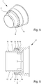
- Fig. 2 shows an enlarged longitudinal layer of a hose end 3 of the hose according to the invention Fig. 1 , wherein the hose 1 is shown only over a partial length.
- the hose 1 has a, preferably corrugated, hose section 2 for a drinking water-carrying system for guiding a drinking water flow. How from the 1 and 2 results, a connector 4 is provided at a hose end 3.
- the connector 4 is designed, for example, to connect the hose end 3 to a complementary connector of a sanitary fitting or to connect to a connector of a water supply line, in particular a corner valve.
- the hose 1 preferably has only one hose section 2.
- the other, not in the 1 and 2 The illustrated hose end 21 of the hose 1 can preferably be of the same design.
- An identical connector 4 or a connector 22 with a different connector geometry can be attached to the other hose end 21.
- a particularly preferred embodiment of the other hose end 21 is shown in FIG Fig. 7 , 8th shown.
- the hose section 2 and the connecting piece 4 are joined together by a welding process.
- the 1 and 2 show the hose end 3 and the connector 4 in a welded state while Fig. 3 shows the hose section 2 and the connector 4 in an unwelded state, in which the welding process can be started.
- Fig. 4 shows the hose section 2 before connecting to the connector 4.
- the hose section 2 has at least one hose end 3 a joining area 5.
- the joining area 5 is formed by a tubular end piece of the hose section 2 that is rotationally symmetrical in the axial direction, the joining area 5 essentially being one has axial end face 6, a substantially radial inner surface 7 and a substantially radial outer surfaces 8.
- the radial inner surface 7 is non-corrugated and adjoins a corrugated inner surface of the hose section 2.
- the hose section 2 is preferably produced by extrusion.
- All parts of the hose section 2, in particular one, preferably corrugated, main section 2A and the different hose ends 3, 21 of the hose section 2 and / or the joining area 5 are particularly preferably produced by extrusion in a common, preferably continuous and / or uninterrupted, extrusion process. This enables a particularly simple and inexpensive production of the hose section 2.
- connection piece 4 is in the 5 and 6 shown.
- connection piece 4 has a rotationally symmetrical axial receiving groove 9 for a hose end 3 of the hose section 2, the joining area 5 of the hose section 2 only extending over a partial length of the rotationally symmetrical tubular end piece of the hose section 2.
- the receiving groove 9 is formed between a cylindrical, shorter, radially outer wall section 10 and a cylindrical, longer, radially inner further wall section 11 projecting beyond the outer wall section 10 in the axial direction.
- the receiving groove 9 thus defines a joining zone 12 in which the welded connection between the hose section 2 and the connector 4 is formed.
- the wall sections 10, 11 are preferably rotationally symmetrical.
- the radially outer wall section 10 has a first inner surface 13 and an axially spaced-apart second inner surface 14, the two inner surfaces 13, 14 being radially spaced apart or at different distances from the axis of rotation of the connecting piece 4.
- the inner surface 13 faces an opening of the receiving groove 9 in the axial direction.
- the inner surfaces 13, 14 are over a inclined connecting surface 15 connected to each other.
- a cross-sectional widening in the form of a step could also be formed axially in this area between the inner surfaces 13, 14.
- the radially inner wall section 11 has a joining surface 16 in the region of the receiving groove 9 and an insertion surface 17 adjacent to the hose section, the joining surface 16 and the insertion surface 17 being spaced radially from one another and connected to one another via a run-up slope 18.
- the joining surface 16 extends over the entire length of the joining zone 12.
- the insertion surface 17 extends outside the receiving groove 9 in the axial direction.
- the wall sections 10, 11 of the connector 4 are connected to one another via a radial groove base 19.
- the joining area 5 is inserted or inserted into the receiving groove 9.
- the insertion surface 17, which merges into a chamfer at its end in the axial direction, and the run-up slope 18 simplify the insertion of the joining area 5 at the hose end 3 of the hose section 2 into the receiving groove 9 of the connector 4.
- the joining area 5 becomes as far as possible in the receiving groove 9 inserted until the hose end 3 axially abuts the connector 4.
- the hose section 2 and the connecting piece 4 are preferably joined to one another by means of a rotary friction welding process.
- one of the two joining partners is set in rotation, while the other joining partner does not perform any rotational movement and is pressed against the first joining partner under pressure.
- the tube section 2 preferably does not rotate during the rotary welding, while the connecting piece 4 is set in rotation. Due to the resulting friction of the surfaces of the hose section 2 and the connecting piece 4 touching, the plastic material melts in these areas.
- the inner surface 7 and the outer surface 8 preferably melt at least in sections and the end surface 6 completely.
- the two inner surfaces 13, 14 and the connecting surface 15 of the radially outer wall section 10 and the outer surface 16 of the radially inner wall section 11 and the radial groove base surface 18 melt at least in sections, preferably over the entire surface.
- the joining area 5 is pressed deeper into the receiving groove 9 during the welding process. Due to the reduced viscosity of the material, air that is still present can escape from the receiving groove 9.
- the joining area 5 preferably completely fills the receiving groove 9 after the welding process.
- the rotation of the connecting piece 4 is stopped. Further heating of the material is prevented and solidification is initiated at the same time.
- the joining pressure is maintained or can be increased further so that the material cools and hardens under pressure. When the material has cooled completely, the joining pressure can be reduced to normal pressure.
- a welding connection 20 is preferably formed by rotary welding (schematically in FIG Fig. 2 shown), which extends in the axial direction over the entire groove depth and in the circumferential direction over the entire circumference of the hose end 3.
- the strength of the welded joint 20 is thereby increased.
- the strength of the welded joint 20 is preferably in the range of the material strength.
- the welding process can be designed so that, in particular with regard to the joining pressure of the joining partners, the rotation speed and the duration of the welding process, the welded connection 20 between the hose end 3 and the connecting piece 4 does not extend in the radial direction to the inner surface and / or to the outer Surface of the connector 4 extends. In the welded state, the inner cylindrical surface and / or the outer cylindrical surface of the connection piece is thus retained undeformed.
- the hose section 2 and the connecting piece 4 preferably consist of the same plastic material. However, it is also possible that the hose section 2 and the connector 4 consist of different plastic materials.
- the hose 1 to 4 show the hose 1 only in the area of a first hose end 3.
- the hose 1 preferably has a further connection piece 22 at the opposite end 21.
- the hose end 21 can be designed at least essentially like the hose end 3, for example with a further joining area 5.
- the further connection piece 22 can be joined to the hose end 21.
- other solutions are also possible here.
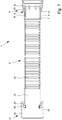
- Fig. 7 and 8th show a second embodiment of the hose 1, in which the two hose ends 3, 21 and the two connecting pieces 4, 22 are designed differently.
- the previous statements preferably apply accordingly, even if a repeated description is dispensed with.
- the hose end 3 and the connecting piece 4 are joined together in the second embodiment as described above. It is therefore primarily dealt with the formation of the other hose end 21 and the further connector 22.
- Fig. 7 shows the hose 1 according to the second embodiment in a longitudinal section.
- Fig. 8 shows an enlarged section of the hose 1 according to Fig. 7 in the area of the second hose end 21 or second connection piece 22.
- connection piece 22 is preferably designed to connect the hose 1 to a corresponding connection piece of a customer and / or, particularly preferably, a water supply line.
- the further connection piece 22 is preferably formed or shaped by the hose section 2 or the second hose end 21.
- the further connection piece 22 is formed or shaped in one piece with the hose section 2 and / or connects in one piece to the main section 2A of the hose section 2.
- the further connection piece 22 is particularly preferably formed or shaped in a common extrusion process with the main section 2A or hose section 2 or second hose end 21.
- the further connection piece 22 preferably has a shoulder 23.
- the shoulder 23 is formed in particular on the circumferential side of the hose section 2 or second hose end 21 and / or extends in the radial direction or transversely to the longitudinal extent of the hose 1 or the hose section 2 or the second hose end 21.
- connection piece 22 or the shoulder 23 preferably forms an abutment or a stop for a coupling ring 24, in particular a coupling nut.
- the collar ring 24 is preferably formed in one piece.
- the coupling ring 24 preferably has a central opening through which the hose section 2 is guided or pushed.
- the coupling ring 24 surrounds the hose 1 or hose section 2 on the circumference or over the entire circumference.
- the hose 1 can preferably be connected via the coupling ring 24 to a corresponding connecting piece of a customer and / or, particularly preferably, a water supply line.
- the coupling ring 24 preferably has an internal thread, in particular for a corresponding external thread of the corresponding connecting piece.
- other solutions are also possible here.
- the further connection piece 22 is preferably not designed directly for connection to a consumer or a water supply line.
- the hose 1 can preferably be connected indirectly via the connecting piece 22, in particular by connecting the coupling ring 24 to a corresponding connecting piece of a customer or a water supply.
- the connecting piece 22 forms an abutment for bracing the coupling ring 24.
- the second hose end 21 or the connector 22 can be connected directly to a corresponding connector.
- the connector 22 can be designed as an external thread for a corresponding internal thread of the corresponding connector.
- the union ring 24, in particular a union nut, can be dispensed with.
- the second hose end 21 preferably has a radially circumferential holding area and / or receiving area 25 for holding and / or receiving a sealing element 26, preferably a sealing ring.
- the sealing element 26 can preferably be pushed and / or plugged onto the receiving area up to the connection piece 22 or the shoulder 23 formed therefrom.
- a radial seal can also be provided.
- the joined connecting piece 4 preferably forms a shoulder 27 or an abutment for the coupling ring 24, as for example in FIG Fig. 7 shown.
- the shoulder 27 is formed in particular on the circumferential side of the connector 4 and / or extends in the radial direction or transversely to the longitudinal extent of the hose 1 or the hose section 2 or the connector 4.
- the coupling ring 24 is preferably held captively or non-detachably on the hose 1 or the hose section 2.
- the coupling ring 24 is particularly preferably pulled onto the hose section 2 before the connection piece 4 is joined at the first hose end 3.
- the coupling ring 24 preferably has an opening with a larger diameter than the hose section 2 or the first hose end 3 or the joining area 5.
- the connector 4 is then permanently attached to the first hose end 3 or joining area 5 by joining.
- the shoulder 27 formed by the connecting piece 4 preferably has a larger diameter than the opening of the union ring 24, so that the union ring 24 can no longer be pulled from the first hose end 3 or separated from the hose 1 via the first hose end 3.
- the (joined) connector 4 can preferably be connected directly to a corresponding connector.
- the connection piece 4 can have an internal thread, so that the hose 1 can be screwed onto a corresponding external thread of a corresponding connection piece.
- a connector 4 with an external thread or other fastening means such as a bayonet catch.
- the first hose end 3 can be connected by means of a (further) union ring, in particular a (further) union nut.
- the shoulder 27 of the connector 4 then forms a stop or an abutment for the (further) coupling ring.
- the hose 1 can preferably be connected via the (further) coupling ring to a corresponding connection piece of a water supply and / or, particularly preferably, a consumer.
- the hose 1 preferably has two coupling rings 24, one coupling ring 24 being assigned to the further connection piece 22 at the hose end 21 and another coupling ring 24 being assigned to the (joined) connection piece 4 at the hose end 3.
- the connecting pieces 4, 22 each form a shoulder 23, 27 for the respective coupling ring 24, in particular as an abutment for bracing.
- both connecting pieces 4, 22 can be connected indirectly to a customer or a water supply line via the respective coupling ring 24.
- the hose section 2 is first produced, particularly preferably with the connector 22 and / or the joining area 5, preferably by extrusion.
- the hose section 2 is extruded together with the connector 22 and / or the joining area 5.
- a corresponding connector 22 is permanently connected to the hose end 21 by joining in an optional further step.
- the hose section 2 with the hose end 3 or the joining area 5 is or are guided through one or two coupling ring (s) 24, in particular the central opening (s) of the coupling ring (s) 24 the coupling ring (s) 24 is pushed or inserted over the hose end 3 or the joining area 5 onto the hose section 2.
- the union ring (s) 24 is / are already secured against removal at the hose end 21 by the (joined or extruded) connector 22.
- the connecting piece 4 is permanently connected to the hose end 3 or joining area 5 by joining, in particular as described at the beginning. This prevents removal of the union ring (s) 24 on the hose end 3.
- the hose 1 or the hose section 2 or the connection piece (s) 4, 22 or the union ring (s) 24 is / are preferably for the drinking water installation trained or suitable for carrying drinking water or coming into contact with drinking water.
- the components of the hose 1 can also include further elements or materials, for example the union ring (s) 24, sealing elements, adhesives or the like.
- “Drinking water installation” in the sense of the present invention is preferably the entirety of the pipelines, fittings and apparatus which are located between the point at which the drinking water is transferred from a water supply system, for example waterworks, to the user and the point at which drinking water is drawn off.
- “Drinking water” is preferably water for human use, in particular for consumption.
- the German “Ordinance on the Quality of Water for Human Use” contains definitions and protective regulations for drinking water. This represents an implementation of the EC Directive 98/83 / EC "On the Quality of Water for Human Use” into national law. "Drinking water” in the sense of the present invention is preferably as in the EC Directive or its national implementations , in particular as defined in the German Drinking Water Ordinance.
- Drinking water is all water that, in its original state or after preparation, is intended for drinking, for cooking, for preparing food and drinks, for personal hygiene and cleaning, for cleaning objects that come into contact with food as intended, or for cleaning objects that are not only intended to come into temporary contact with the human body. Furthermore, drinking water is all water that is used in a food business for the manufacture, treatment, preservation or placing on the market of products or substances that are intended for human consumption.
- the drinking water must be such that its enjoyment or use does not cause harm to human health, particularly pathogens. It must also be pure and fit for consumption. In particular, pathogens and chemical substances must not be present in drinking water in concentrations that cause harm to human health. Concentrations of microorganisms and chemical substances that contaminate the drinking water or can have an adverse effect on its quality should be kept as low as is possible under reasonable general effort, taking individual cases into account, according to the generally recognized rules of technology. Furthermore, drinking water must not contain any substances that contain one or more radionuclides, the activity or concentration of which cannot be neglected from the point of view of radiation protection.
- microorganisms, chemical substances and radioactive substances do not exceed the limit values specified in Annexes 1-3 of the German Drinking Water Ordinance.
- the hose 1 preferably fulfills the "Requirements for plants for the production, treatment or distribution of drinking water" according to ⁇ 17 of the German Drinking Water Ordinance.
- the hose 1 must not directly or indirectly reduce the protection of human health provided for by the Drinking Water Ordinance, subsequently change the smell or taste of the water, or release substances into the drinking water in quantities that are greater than if the generally recognized rules of technology are observed is inevitable.
- the components of the hose 1, in particular the hose section 2 and the connecting piece 4 or the connecting pieces 4, 22, are preferably chemically compatible with one another and with the water to be passed through.
- the components of the hose 1 therefore preferably do not undergo any chemical reactions with one another or with water.
- there is no corrosion and / or the components of the hose 1 are chemically resistant, in particular retain their characteristic properties despite any length of contact with other components of the hose 1 and / or with water.
- the components or materials of the hose 1 that come into contact with water for human use particularly preferably all materials or
- Components of the hose 1 do not pose any health risk and preferably do not cause any changes in the drinking water in terms of its nature or appearance, smell or taste.
- the test of the hose 1 with regard to the fact that it is suitable for drinking water installation, in particular that it corresponds to the requirements of the Drinking Water Ordinance, is preferably carried out according to the specifications according to "DVGW KTW” or “DVGW W 270", particularly preferably according to the " Guideline for the hygienic assessment of organic materials in contact with drinking water "(KTW guideline) of the German Federal Environment Agency or according to the" Assessment basis for plastics and other organic materials in contact with drinking water "(KTW-BWGL) of the German Federal Environment Agency.
- the hose 1 is checked in particular for the migration of substances and the promotion of microbial growth.
- the hose 1 is preferably tested on the finished end product, but can additionally or alternatively also be carried out separately for the hose section 2 and the connecting piece 4.
- the test of the hose 1 for migration of substances is preferably carried out by filling the hose 1 with (dechlorinated) drinking water.
- the hose ends or the connecting piece 4 or the connecting pieces 4, 22 are preferably additionally checked by immersing them in (dechlorinated) drinking water.
- the resulting water is called migration water in the following.
- the test is preferably carried out with cold water as well as with warm water and hot water.
- Cold water is preferably water with a temperature between 21 ° C and 25 ° C, in particular of 23 ° C.
- Hot water is preferably water with a temperature between 58 ° C and 62 ° C, in particular of 60 ° C.
- Hot water is preferably water with a temperature between 83 ° C and 87 ° C, in particular 85 ° C.
- the migration water is preferably brought into contact with the hose 1 for 10 days, particularly preferably for 31 days.
- the migration waters are examined for the migration of substances, in particular for the parameters odor, turbidity, color, foaming and total organic carbon (TOC).
- the test is preferably carried out in accordance with DIN EN 1420 and / or DIN EN 12873.
- the migration water after 10 days of contact, in particular after 31 days of contact, with hose 1 preferably does not exceed the limit values specified in the KTW guidelines or the KTW evaluation basis or other suitable guidelines or evaluation bases.
- no increasing trend of the parameters can be determined over the measurement period.
- the test for promoting microbial growth is preferably carried out in accordance with DIN EN 16421, in particular the biomass production potential process (BPP process) or the volumetric process described therein.
- the hose 1 preferably has only a firmly adhering surface area or surface growth which is less than or equal to 0.07 ml / 800 cm 2 , in particular less than or equal to 0.05 ml / 800 cm 2 .
- the hose 1 preferably has a surface growth or a surface settlement greater than 0, and therefore has no biocidal effect on the drinking water.
Landscapes
- Engineering & Computer Science (AREA)
- Mechanical Engineering (AREA)
- General Engineering & Computer Science (AREA)
- Health & Medical Sciences (AREA)
- Life Sciences & Earth Sciences (AREA)
- Hydrology & Water Resources (AREA)
- Public Health (AREA)
- Water Supply & Treatment (AREA)
- Rigid Pipes And Flexible Pipes (AREA)
Applications Claiming Priority (6)
| Application Number | Priority Date | Filing Date | Title |
|---|---|---|---|
| DE102018009532 | 2018-12-07 | ||
| DE102018132712 | 2018-12-18 | ||
| DE202018107249 | 2018-12-18 | ||
| DE202018107369 | 2018-12-21 | ||
| DE102019003667.0A DE102019003667A1 (de) | 2018-12-07 | 2019-05-27 | Schlauch und Anschlussstück für einen Schlauch |
| DE202019002277.5U DE202019002277U1 (de) | 2018-12-07 | 2019-05-27 | Schlauch und Anschlussstück für einen Schlauch |
Publications (3)
| Publication Number | Publication Date |
|---|---|
| EP3663471A1 true EP3663471A1 (fr) | 2020-06-10 |
| EP3663471C0 EP3663471C0 (fr) | 2024-01-17 |
| EP3663471B1 EP3663471B1 (fr) | 2024-01-17 |
Family
ID=68808134
Family Applications (1)
| Application Number | Title | Priority Date | Filing Date |
|---|---|---|---|
| EP19214062.2A Active EP3663471B1 (fr) | 2018-12-07 | 2019-12-06 | Procédé de fabrication d'un tuyau et tuyau |
Country Status (1)
| Country | Link |
|---|---|
| EP (1) | EP3663471B1 (fr) |
Cited By (1)
| Publication number | Priority date | Publication date | Assignee | Title |
|---|---|---|---|---|
| EP4403812A1 (fr) * | 2023-01-18 | 2024-07-24 | Witzenmann GmbH | Adaptateur |
Families Citing this family (2)
| Publication number | Priority date | Publication date | Assignee | Title |
|---|---|---|---|---|
| WO2026032997A1 (fr) * | 2024-08-08 | 2026-02-12 | Neoperl Gmbh | Soudage au laser |
| EP4692623A1 (fr) * | 2024-08-08 | 2026-02-11 | Neoperl GmbH | Soudage au laser |
Citations (7)
| Publication number | Priority date | Publication date | Assignee | Title |
|---|---|---|---|---|
| DE4307704A1 (de) * | 1993-03-11 | 1994-09-15 | Wilhelm Hegler | Verfahren zum Verschweißen von aus thermoplastischem Kunststoff bestehenden Rohrstücken |
| DE19654435A1 (de) | 1996-12-30 | 1998-07-09 | Oventrop Sohn Kg F W | Anordnung zur steckbaren Verbindung von Rohren mit Armaturen oder Fittings |
| EP1006304A1 (fr) * | 1998-11-27 | 2000-06-07 | Manuel Gomez Singla | Elément de connexion flexible pour usage sanitaire et son procédé de fabrication |
| EP1640141A2 (fr) * | 2004-09-27 | 2006-03-29 | Veritas Ag | Dispositif, assemblage et procédé pour joindre des tuyaux, véhicule avec un tel dispositif ou assemblage |
| EP2159465B1 (fr) | 2008-08-27 | 2011-03-16 | Kottmann GOSLA GmbH | Tuyau flexible sous pression pour un système de transport d'eau, notamment pour le raccordement d'armatures sanitaires mobiles ou pour la liaison d'éléments du système de transport d'eau |
| EP2333167A1 (fr) * | 2009-12-03 | 2011-06-15 | RE-FLEX S.r.l. | Connecteur avec portion de manchon intégral et tuyau avec ce connecteur |
| DE102010030718A1 (de) * | 2010-06-30 | 2012-01-05 | Lisa Dräxlmaier GmbH | Rohrverbindung und Verfahren zur Herstellung einer solchen Rohrverbindung |
-
2019
- 2019-12-06 EP EP19214062.2A patent/EP3663471B1/fr active Active
Patent Citations (7)
| Publication number | Priority date | Publication date | Assignee | Title |
|---|---|---|---|---|
| DE4307704A1 (de) * | 1993-03-11 | 1994-09-15 | Wilhelm Hegler | Verfahren zum Verschweißen von aus thermoplastischem Kunststoff bestehenden Rohrstücken |
| DE19654435A1 (de) | 1996-12-30 | 1998-07-09 | Oventrop Sohn Kg F W | Anordnung zur steckbaren Verbindung von Rohren mit Armaturen oder Fittings |
| EP1006304A1 (fr) * | 1998-11-27 | 2000-06-07 | Manuel Gomez Singla | Elément de connexion flexible pour usage sanitaire et son procédé de fabrication |
| EP1640141A2 (fr) * | 2004-09-27 | 2006-03-29 | Veritas Ag | Dispositif, assemblage et procédé pour joindre des tuyaux, véhicule avec un tel dispositif ou assemblage |
| EP2159465B1 (fr) | 2008-08-27 | 2011-03-16 | Kottmann GOSLA GmbH | Tuyau flexible sous pression pour un système de transport d'eau, notamment pour le raccordement d'armatures sanitaires mobiles ou pour la liaison d'éléments du système de transport d'eau |
| EP2333167A1 (fr) * | 2009-12-03 | 2011-06-15 | RE-FLEX S.r.l. | Connecteur avec portion de manchon intégral et tuyau avec ce connecteur |
| DE102010030718A1 (de) * | 2010-06-30 | 2012-01-05 | Lisa Dräxlmaier GmbH | Rohrverbindung und Verfahren zur Herstellung einer solchen Rohrverbindung |
Non-Patent Citations (1)
| Title |
|---|
| "RÖMPP Lexikon Chemie", vol. 3, 1996 |
Cited By (1)
| Publication number | Priority date | Publication date | Assignee | Title |
|---|---|---|---|---|
| EP4403812A1 (fr) * | 2023-01-18 | 2024-07-24 | Witzenmann GmbH | Adaptateur |
Also Published As
| Publication number | Publication date |
|---|---|
| EP3663471C0 (fr) | 2024-01-17 |
| EP3663471B1 (fr) | 2024-01-17 |
Similar Documents
| Publication | Publication Date | Title |
|---|---|---|
| EP3663471B1 (fr) | Procédé de fabrication d'un tuyau et tuyau | |
| EP3592526B1 (fr) | Tuyau à pression et procédé de fabrication d'un tuyau à pression | |
| WO2005010420A1 (fr) | Element de raccord filete et gaine protectrice pour celui-ci | |
| EP3742034B1 (fr) | Agencement de tuyau et utilisation | |
| DE102008006068B3 (de) | Schweißsystem für mehrschichtige Verbundrohre aus Kunststoff und Metall | |
| DE202019103965U1 (de) | Schlauch und Anschlussgarnitur, Auslaufgarnitur und Armatur mit einem Schlauch | |
| DE60303118T2 (de) | Rohrverbinder mit mindestens zwei lagen aus unterschiedlichem material, wobei die innerste schicht aus kunststoff besteht | |
| DE202008001101U1 (de) | Schweißsystem für mehrschichtige Verbundrohre aus Kunststoff und Metall | |
| DE202019002277U1 (de) | Schlauch und Anschlussstück für einen Schlauch | |
| DE102009048578B4 (de) | Verbindungselement zum Verschweißen von Kunststoffrohren | |
| EP1369635A1 (fr) | Raccord de tuyauterie pour le transport de fluides, notamment pour système de conduite d'eau | |
| DE102007036324B4 (de) | Erdwärmesonden-Rohrformteil | |
| EP1920685A2 (fr) | Agencement de liaison de conduite de fluide | |
| DE2600621C3 (de) | Gewindelose Verbindung für Rohre und Verfahren zu ihrer Herstellung | |
| DE102005004372B4 (de) | Verfahren zum Verbinden poröser Membranen sowie hierdurch erzeugte Membranfiltervorrichtung | |
| DE102008062874B4 (de) | Ventilgehäusekörper | |
| DE202009019040U1 (de) | Mehrschichtverbundrohr | |
| EP0728978B1 (fr) | Tuyau souple sanitaire avec accouplement tournant d'un raccord | |
| DE102004026897A1 (de) | Armatur | |
| EP1703192A1 (fr) | Raccord à baionnette | |
| DE19961047C2 (de) | Verfahren zum Anschluß eines Mehrschichtverbundrohres und Verbindungsstelle sowie Bauteil zur Erwärmung der Materialschichten eines Mehrschichtverbundrohres | |
| DE4112369A1 (de) | Verbindungselement fuer rohre | |
| DE202012001877U1 (de) | Kupplungselement für eine Schlauchkupplung | |
| DE102007059182B4 (de) | Verfahren zum Herstellen einer unlösbaren Verbindung sowie unlösbare Verbindung zwischen einem Fitting und einem Rohr, Fitting für ein Rohr mit einem vorgegebenen Innendurchmesser und lösbare Verbindung zwischen mindestens einem Fitting und einem Fittinggrundkörper | |
| AT216848B (de) | Vorrichtung zur Herstellung einer dichten Verbindung von Rohren, Schläuchen, Armaturen od. dgl. |
Legal Events
| Date | Code | Title | Description |
|---|---|---|---|
| PUAI | Public reference made under article 153(3) epc to a published international application that has entered the european phase |
Free format text: ORIGINAL CODE: 0009012 |
|
| STAA | Information on the status of an ep patent application or granted ep patent |
Free format text: STATUS: THE APPLICATION HAS BEEN PUBLISHED |
|
| AK | Designated contracting states |
Kind code of ref document: A1 Designated state(s): AL AT BE BG CH CY CZ DE DK EE ES FI FR GB GR HR HU IE IS IT LI LT LU LV MC MK MT NL NO PL PT RO RS SE SI SK SM TR |
|
| AX | Request for extension of the european patent |
Extension state: BA ME |
|
| STAA | Information on the status of an ep patent application or granted ep patent |
Free format text: STATUS: REQUEST FOR EXAMINATION WAS MADE |
|
| 17P | Request for examination filed |
Effective date: 20201208 |
|
| RBV | Designated contracting states (corrected) |
Designated state(s): AL AT BE BG CH CY CZ DE DK EE ES FI FR GB GR HR HU IE IS IT LI LT LU LV MC MK MT NL NO PL PT RO RS SE SI SK SM TR |
|
| STAA | Information on the status of an ep patent application or granted ep patent |
Free format text: STATUS: EXAMINATION IS IN PROGRESS |
|
| 17Q | First examination report despatched |
Effective date: 20220414 |
|
| GRAP | Despatch of communication of intention to grant a patent |
Free format text: ORIGINAL CODE: EPIDOSNIGR1 |
|
| STAA | Information on the status of an ep patent application or granted ep patent |
Free format text: STATUS: GRANT OF PATENT IS INTENDED |
|
| INTG | Intention to grant announced |
Effective date: 20230714 |
|
| GRAS | Grant fee paid |
Free format text: ORIGINAL CODE: EPIDOSNIGR3 |
|
| GRAA | (expected) grant |
Free format text: ORIGINAL CODE: 0009210 |
|
| STAA | Information on the status of an ep patent application or granted ep patent |
Free format text: STATUS: THE PATENT HAS BEEN GRANTED |
|
| AK | Designated contracting states |
Kind code of ref document: B1 Designated state(s): AL AT BE BG CH CY CZ DE DK EE ES FI FR GB GR HR HU IE IS IT LI LT LU LV MC MK MT NL NO PL PT RO RS SE SI SK SM TR |
|
| REG | Reference to a national code |
Ref country code: GB Ref legal event code: FG4D Free format text: NOT ENGLISH |
|
| REG | Reference to a national code |
Ref country code: CH Ref legal event code: EP |
|
| REG | Reference to a national code |
Ref country code: DE Ref legal event code: R096 Ref document number: 502019010400 Country of ref document: DE |
|
| REG | Reference to a national code |
Ref country code: IE Ref legal event code: FG4D Free format text: LANGUAGE OF EP DOCUMENT: GERMAN |
|
| U01 | Request for unitary effect filed |
Effective date: 20240208 |
|
| U07 | Unitary effect registered |
Designated state(s): AT BE BG DE DK EE FI FR IT LT LU LV MT NL PT SE SI Effective date: 20240219 |
|
| PG25 | Lapsed in a contracting state [announced via postgrant information from national office to epo] |
Ref country code: IS Free format text: LAPSE BECAUSE OF FAILURE TO SUBMIT A TRANSLATION OF THE DESCRIPTION OR TO PAY THE FEE WITHIN THE PRESCRIBED TIME-LIMIT Effective date: 20240517 |
|
| PG25 | Lapsed in a contracting state [announced via postgrant information from national office to epo] |
Ref country code: GR Free format text: LAPSE BECAUSE OF FAILURE TO SUBMIT A TRANSLATION OF THE DESCRIPTION OR TO PAY THE FEE WITHIN THE PRESCRIBED TIME-LIMIT Effective date: 20240418 |
|
| PG25 | Lapsed in a contracting state [announced via postgrant information from national office to epo] |
Ref country code: RS Free format text: LAPSE BECAUSE OF FAILURE TO SUBMIT A TRANSLATION OF THE DESCRIPTION OR TO PAY THE FEE WITHIN THE PRESCRIBED TIME-LIMIT Effective date: 20240417 Ref country code: HR Free format text: LAPSE BECAUSE OF FAILURE TO SUBMIT A TRANSLATION OF THE DESCRIPTION OR TO PAY THE FEE WITHIN THE PRESCRIBED TIME-LIMIT Effective date: 20240117 |
|
| PG25 | Lapsed in a contracting state [announced via postgrant information from national office to epo] |
Ref country code: ES Free format text: LAPSE BECAUSE OF FAILURE TO SUBMIT A TRANSLATION OF THE DESCRIPTION OR TO PAY THE FEE WITHIN THE PRESCRIBED TIME-LIMIT Effective date: 20240117 |
|
| PG25 | Lapsed in a contracting state [announced via postgrant information from national office to epo] |
Ref country code: RS Free format text: LAPSE BECAUSE OF FAILURE TO SUBMIT A TRANSLATION OF THE DESCRIPTION OR TO PAY THE FEE WITHIN THE PRESCRIBED TIME-LIMIT Effective date: 20240417 Ref country code: NO Free format text: LAPSE BECAUSE OF FAILURE TO SUBMIT A TRANSLATION OF THE DESCRIPTION OR TO PAY THE FEE WITHIN THE PRESCRIBED TIME-LIMIT Effective date: 20240417 Ref country code: IS Free format text: LAPSE BECAUSE OF FAILURE TO SUBMIT A TRANSLATION OF THE DESCRIPTION OR TO PAY THE FEE WITHIN THE PRESCRIBED TIME-LIMIT Effective date: 20240517 Ref country code: HR Free format text: LAPSE BECAUSE OF FAILURE TO SUBMIT A TRANSLATION OF THE DESCRIPTION OR TO PAY THE FEE WITHIN THE PRESCRIBED TIME-LIMIT Effective date: 20240117 Ref country code: GR Free format text: LAPSE BECAUSE OF FAILURE TO SUBMIT A TRANSLATION OF THE DESCRIPTION OR TO PAY THE FEE WITHIN THE PRESCRIBED TIME-LIMIT Effective date: 20240418 Ref country code: ES Free format text: LAPSE BECAUSE OF FAILURE TO SUBMIT A TRANSLATION OF THE DESCRIPTION OR TO PAY THE FEE WITHIN THE PRESCRIBED TIME-LIMIT Effective date: 20240117 |
|
| PG25 | Lapsed in a contracting state [announced via postgrant information from national office to epo] |
Ref country code: PL Free format text: LAPSE BECAUSE OF FAILURE TO SUBMIT A TRANSLATION OF THE DESCRIPTION OR TO PAY THE FEE WITHIN THE PRESCRIBED TIME-LIMIT Effective date: 20240117 |
|
| PG25 | Lapsed in a contracting state [announced via postgrant information from national office to epo] |
Ref country code: PL Free format text: LAPSE BECAUSE OF FAILURE TO SUBMIT A TRANSLATION OF THE DESCRIPTION OR TO PAY THE FEE WITHIN THE PRESCRIBED TIME-LIMIT Effective date: 20240117 |
|
| PG25 | Lapsed in a contracting state [announced via postgrant information from national office to epo] |
Ref country code: SM Free format text: LAPSE BECAUSE OF FAILURE TO SUBMIT A TRANSLATION OF THE DESCRIPTION OR TO PAY THE FEE WITHIN THE PRESCRIBED TIME-LIMIT Effective date: 20240117 |
|
| REG | Reference to a national code |
Ref country code: DE Ref legal event code: R097 Ref document number: 502019010400 Country of ref document: DE |
|
| PG25 | Lapsed in a contracting state [announced via postgrant information from national office to epo] |
Ref country code: CZ Free format text: LAPSE BECAUSE OF FAILURE TO SUBMIT A TRANSLATION OF THE DESCRIPTION OR TO PAY THE FEE WITHIN THE PRESCRIBED TIME-LIMIT Effective date: 20240117 |
|
| PG25 | Lapsed in a contracting state [announced via postgrant information from national office to epo] |
Ref country code: SK Free format text: LAPSE BECAUSE OF FAILURE TO SUBMIT A TRANSLATION OF THE DESCRIPTION OR TO PAY THE FEE WITHIN THE PRESCRIBED TIME-LIMIT Effective date: 20240117 |
|
| PG25 | Lapsed in a contracting state [announced via postgrant information from national office to epo] |
Ref country code: SM Free format text: LAPSE BECAUSE OF FAILURE TO SUBMIT A TRANSLATION OF THE DESCRIPTION OR TO PAY THE FEE WITHIN THE PRESCRIBED TIME-LIMIT Effective date: 20240117 Ref country code: SK Free format text: LAPSE BECAUSE OF FAILURE TO SUBMIT A TRANSLATION OF THE DESCRIPTION OR TO PAY THE FEE WITHIN THE PRESCRIBED TIME-LIMIT Effective date: 20240117 Ref country code: RO Free format text: LAPSE BECAUSE OF FAILURE TO SUBMIT A TRANSLATION OF THE DESCRIPTION OR TO PAY THE FEE WITHIN THE PRESCRIBED TIME-LIMIT Effective date: 20240117 Ref country code: CZ Free format text: LAPSE BECAUSE OF FAILURE TO SUBMIT A TRANSLATION OF THE DESCRIPTION OR TO PAY THE FEE WITHIN THE PRESCRIBED TIME-LIMIT Effective date: 20240117 |
|
| PLBE | No opposition filed within time limit |
Free format text: ORIGINAL CODE: 0009261 |
|
| STAA | Information on the status of an ep patent application or granted ep patent |
Free format text: STATUS: NO OPPOSITION FILED WITHIN TIME LIMIT |
|
| 26N | No opposition filed |
Effective date: 20241018 |
|
| U20 | Renewal fee for the european patent with unitary effect paid |
Year of fee payment: 6 Effective date: 20241217 |
|
| PG25 | Lapsed in a contracting state [announced via postgrant information from national office to epo] |
Ref country code: MC Free format text: LAPSE BECAUSE OF FAILURE TO SUBMIT A TRANSLATION OF THE DESCRIPTION OR TO PAY THE FEE WITHIN THE PRESCRIBED TIME-LIMIT Effective date: 20240117 |
|
| REG | Reference to a national code |
Ref country code: CH Ref legal event code: PL |
|
| GBPC | Gb: european patent ceased through non-payment of renewal fee |
Effective date: 20241206 |
|
| PG25 | Lapsed in a contracting state [announced via postgrant information from national office to epo] |
Ref country code: GB Free format text: LAPSE BECAUSE OF NON-PAYMENT OF DUE FEES Effective date: 20241206 |
|
| PG25 | Lapsed in a contracting state [announced via postgrant information from national office to epo] |
Ref country code: CH Free format text: LAPSE BECAUSE OF NON-PAYMENT OF DUE FEES Effective date: 20241231 |
|
| PG25 | Lapsed in a contracting state [announced via postgrant information from national office to epo] |
Ref country code: IE Free format text: LAPSE BECAUSE OF NON-PAYMENT OF DUE FEES Effective date: 20241206 |
|
| U20 | Renewal fee for the european patent with unitary effect paid |
Year of fee payment: 7 Effective date: 20251215 |
|
| PG25 | Lapsed in a contracting state [announced via postgrant information from national office to epo] |
Ref country code: CY Free format text: LAPSE BECAUSE OF FAILURE TO SUBMIT A TRANSLATION OF THE DESCRIPTION OR TO PAY THE FEE WITHIN THE PRESCRIBED TIME-LIMIT; INVALID AB INITIO Effective date: 20191206 |