EP3663480A1 - Toit à lamelles pourvu de pare-gouttes - Google Patents
Toit à lamelles pourvu de pare-gouttes Download PDFInfo
- Publication number
- EP3663480A1 EP3663480A1 EP18000941.7A EP18000941A EP3663480A1 EP 3663480 A1 EP3663480 A1 EP 3663480A1 EP 18000941 A EP18000941 A EP 18000941A EP 3663480 A1 EP3663480 A1 EP 3663480A1
- Authority
- EP
- European Patent Office
- Prior art keywords
- slats
- closed position
- pivoted
- rotation
- roofing
- Prior art date
- Legal status (The legal status is an assumption and is not a legal conclusion. Google has not performed a legal analysis and makes no representation as to the accuracy of the status listed.)
- Granted
Links
Images


Classifications
-
- E—FIXED CONSTRUCTIONS
- E04—BUILDING
- E04F—FINISHING WORK ON BUILDINGS, e.g. STAIRS, FLOORS
- E04F10/00—Sunshades, e.g. Florentine blinds or jalousies; Outside screens; Awnings or baldachins
- E04F10/08—Sunshades, e.g. Florentine blinds or jalousies; Outside screens; Awnings or baldachins of a plurality of similar rigid parts, e.g. slabs, lamellae
- E04F10/10—Sunshades, e.g. Florentine blinds or jalousies; Outside screens; Awnings or baldachins of a plurality of similar rigid parts, e.g. slabs, lamellae collapsible or extensible; metallic Florentine blinds; awnings with movable parts such as louvres
Definitions
- the invention relates to a roof with at least two supports, on which a plurality of slats are each pivotably mounted about an axis of rotation, the axes of rotation of the slats extending from one support to the other support, the slats being driven by a drive from a closed position in which the slats one form a closed roof surface, in particular can be pivoted to any open position, so that part of the slats is pivoted down out of the closed position and other part of the slats is pivoted upwards out of the closed position, which when the slats are pivoted in the direction of rotation to the open position In each case a part of the slats swiveling downward from the closed position of the slats has a drainage channel.
- a disadvantage of known roofing systems is that when the roofing is opened, especially after a precipitation, the precipitation and / or dirt collected on the slats drips due to pivoting of the slats onto the space under the roofing and thus contaminates the room.
- the invention further relates to a method for controlling a roof.
- the object of the invention is to overcome the disadvantages of known roofing and to further develop a roofing in such a way that contamination of the space under the roofing as a result of opening the Canopy is avoided especially after rainfall.
- the opening of the roof or the slats is understood as synonymous with the pivoting of the slats into an open position.
- the drive is designed and / or is controlled by means of a control unit such that before the slats are pivoted into an open position and / or after aDetection of precipitation of the drive automatically
- the precipitation and / or dirt collected on the lamellae flows into the drainage channels of the respective lamellae, in order to drain to the side from there via the respective side edges of the lamellae.
- the water can flow out of the gutter, for example, by means of an inclination of the gutter with respect to the horizontal and / or due to the inclination of the Slats can be guaranteed even against the horizontal. This prevents the precipitation and / or dirt collected on the slats from reaching the space under the roof when the slats are opened.
- the duration of precipitation and / or dirt on the slats can be minimized, so that the risk of damage to the slats such as rust and / or permanent discoloration and / or deflection of the slats, in particular as a result of freezing water on the slats, can be minimized.
- the drive is designed and / or is controlled by means of a control unit such that, before the slats are pivoted into the open position and / or after a precipitation has been detected, the drive automatically slices the slats at least once, in particular several times, by an acute angle of up to pivoted at 15 ° or up to 30 ° or up to 45 ° from the closed position in the direction of rotation to the open position into a drip position and after each pivoting of the slats into the drip position, pivoted back again in the direction of rotation to the closed position, in particular completely into the closed position. This process is called draining.
- the draining according to the invention can take place each time the roof is opened. Alternatively or cumulatively, the draining takes place after the end of precipitation. For example, it can be determined on the basis of the torque to be applied by means of the drive and / or the weight of the lamellae whether there has been precipitation and therefore the dripping must take place.
- precipitation can be detected using a rain sensor.
- the draining can take place after precipitation and / or immediately before opening.
- the drive can have a dripping mechanism.
- a dripping mechanism can be designed, for example, in such a way that the drive has a worm-like gear, the worm gears for pivoting the slats into the dripping position being designed such that the slats at least once in particular after each pivoting into the dripping position, again in the direction of rotation to the closed position, in particular completely pivoted back into the closed position.
- the slats form a closed roof area in the closed position.
- the opening position of the slats means a pivoting position of the slats deviating from the closed position, in particular where the maximum free roof area is created.
- the slats can be pivoted by 90 ° in the open position relative to the closed position.
- the slats can be aligned in the open position by 90 ° with respect to the horizontal.
- the slats can be fixed in any intermediate positions between the closed position and the open position, in particular by stopping the opening process and / or the closing process.
- the slats can be pivoted into any open position in which the slats are at an angle of 1 ° to 175 °, in particular 45 ° or 60 ° or 75 ° or 90 ° or 105 ° or 120 ° or 135 ° or 140 ° or 150 ° or 165 ° or 175 °, are pivoted with respect to the closed position.
- Each slat has a width, a height and a longitudinal extent corresponding to the three spatial dimensions.
- the axes of rotation of the slats run indirectly or directly from one support directly or indirectly to the other support, the actual longitudinal extension of the slat being less than or equal to or greater than the distance between the supports.
- the drainage channel of the lamella can be formed at least partially by means of a longitudinal edge of the lamella, in particular running parallel to the longitudinal extent.
- each lamella can be formed by a longitudinal profile, in particular a hollow profile.
- the longitudinal profile of each slat can be formed in one part or in several parts, in particular from a plurality of longitudinal profiles connected in a form-fitting and / or non-positive and / or material-locking manner.
- the slats can each have a continuous cross section.
- the lamellae can each be mounted so as to be pivotable about an axis of rotation running parallel to their longitudinal extent.
- the swiveling of the slats into the draining position can be carried out in a jerky manner, with the swiveling into the draining position of the slats taking place faster than when the slats are pivoted into the open position.
- the drive can hold the slats in the draining position for at least one second, in particular several seconds, before the slats are pivoted back again.
- precipitation can be detected using a rain sensor.
- the canopy itself can have a control unit and / or can be controlled by an external control unit.
- the control unit can be connected to the roof by means of a cable and / or wirelessly, in particular by means of an infrared connection and / or a Bluetooth connection and / or a radio connection.
- the carriers can run parallel to one another.
- the carriers can run at an angle to one another, the length of the successive lamellae corresponding to the angle between the carriers decreasing.
- the two beams can each be mounted on a lintel.
- one of the beams can be mounted on a lintel.
- the carrier can be supported on the other side by means of at least one in particular vertical post.
- the canopy can be mounted free-standing and supported by several, in particular, vertical posts.
- the canopy preferably has at least one rain sensor.
- precipitation and / or an end of precipitation can be detected, so that the dripping can be initiated accordingly after the precipitation.
- draining can take place after each precipitation.
- water and / or dirt remaining on the slats can be minimized, so that the risk of damage to the slats, such as rust and / or permanent discoloration and / or deflection, in particular as a result of freezing water on the slats, can be minimized.
- the rain sensor can be designed as a permanently energized contact or can have a permanently energized contact. If there is water on the contact, the resistance and / or the temperature of the rain sensor changes so that a start of precipitation can be detected. The water on the rain sensor will evaporated by a certain heating power generated by energizing the rain sensor, so that the resistance and / or the temperature of the rain sensor changes again after the end of precipitation. In this way, both the beginning and the end of the precipitation can be detected.
- the roof preferably has a control unit, in particular a programmable one, by means of which the drive is controlled.
- the control unit By programming the control unit, the canopy can be adapted to the requirements.
- the draining and / or the draining position and / or any open positions can be set as required.
- the part of the slats which swivels upward when the slats are pivoted in the direction of rotation to the open position from the closed position of the slats has a lip.
- the part of the slat that has the drainage channel is pivoted downward.
- another part of the slat is pivoted upwards.
- This part of the lamella which swings upward preferably has a lip.
- such a lip can be formed by a longitudinal edge of the lamella, in particular running parallel to the longitudinal extent, and / or by an additional rubber lip attached to the profile of the lamella.
- a part of the slats swiveling upward from the closed position of the slats each has a lip, wherein at least in the closed position of the slats, the lip of a first slat and the drainage channel of an adjacent slat facing the lip interlock.
- the lip of the first lamella and the drainage channel of the adjacent lamella can correspond and work together in a similar way to the so-called male-female principle.
- a portion of the slats that swings upward from the closed position of the slats has a lip, the lip of a first slat being directly or indirectly, in particular sealingly, in particular watertightly via at least one sealing element the gutter corresponds to an adjacent lamella.
- water cannot flow between the lip of the first lamella and the trough of the adjacent lamella, especially when the water flows over the drainage channel. This prevents water and / or dirt between the slats from reaching the space under the roof in the event of heavy precipitation in the closed position of the slats.
- the lip of the first lamella can form a water drain to the drainage channel of the adjacent lamella. This allows the water drainage into the gutters to be optimized.
- At least one of the slats in particular each slat, can have an upper side which is coated in such a way that the water collected on the slat easily flows off.
- a coating can be water-repellent and / or particularly smooth.
- the surface of the upper side can be machined and / or manufactured, in particular by filing and / or grinding and / or milling, that the surface is particularly smooth.
- At least one of the carriers preferably has a rain gutter.
- the rain gutter can be arranged laterally next to the carrier and / or running parallel to the carrier. This allows the water flowing out of the gutters to be collected and drained in the gutter.
- the rain gutter can be inclined with respect to the horizontal.
- the slats are preferably inclined with respect to their longitudinal extent with respect to the horizontal.
- the lamellae can each be inclined downwards in the direction of the carrier having a rain gutter. Thereby the water flowing out of the gutters can be collected and drained in the gutter.
- the slats can be inclined with respect to their horizontal extension at an acute angle of up to 45 °, in particular by 5 ° or 10 ° or 15 ° or 20 ° or 25 ° or 30 ° or 35 ° or 40 °, with respect to the horizontal.
- the canopy preferably has at least one in particular vertical post which supports at least one of the supports.
- One of the beams can be mounted on a lintel, while the other beam can be supported by the at least one post.
- a beam can be supported by at least one, in particular two, posts.
- the canopy preferably has at least one in particular vertical post which supports at least one of the supports, the post having a downpipe for draining water, in particular water, from the support supported by the post.
- the post can be formed by a hollow profile.
- the downpipe can be received in the hollow profile of the post.
- the canopy preferably has a frame formed from a plurality of supports.
- the frame can be carried by several, in particular four, posts arranged at the corners of the frame.
- the frame can be mounted on one or more lintels.
- At least one of the supports preferably has a rain gutter and the roofing has at least one, in particular vertical, post that supports the support, wherein a drain bend is arranged which leads from the rain gutter to the post, in particular to a downpipe arranged in the post. This allows the water to be drained from the gutter through the drain elbow to the post. This ensures adequate rainwater drainage.
- the rain gutter can be arranged laterally next to the support, running parallel to the support, and the drainage arch can be guided to the post and / or to the downpipe by notching the support.
- the carrier can have an insert that is inserted in a notch of the carrier and in particular can be removed downwards, in which the drain bend is arranged, in particular wherein the insert is accommodated in the carrier in a form-fitting and / or non-positive manner.
- such an insert can also be formed in one piece with the drain elbow.
- the discharge elbow can have a heating device, in particular an electrical resistance heater.
- the rain gutter can be formed by a gutter profile and the drain elbow can be connected to the gutter by means of a socket lying in a recess in the gutter profile.
- the downpipe can have a connection piece with a socket, in particular a connection piece in the form of an angle, the outlet bend opening into the socket of the connection piece of the downpipe.
- the drain bend and / or a socket for connecting the drain bend to the rain gutter and / or a socket for connecting the drain bend to the downspout and / or the gutter and / or the downpipe can have an especially removable sieve.
- the invention further relates to a method for controlling a roof with at least two supports, on which a plurality of slats are each pivotably mounted about an axis of rotation, the axes of rotation of the slats running from one support to the other support, the slats being driven from a closed position by means of a drive, in which the slats are closed Form roof surface, can be pivoted into any open position in particular, so that part of the slats is pivoted downwards from the closed position and other part of the slats is pivoted upwards out of the closed position, with the slats being pivoted in the direction of rotation to the open position a part of the slats swiveling downward from the closed position of the slats has a drainage channel.
- the drive automatically drives the slats at least once, in particular several times, by an acute angle, in particular up to 15 ° or up to 30 ° or up to 45 °, from the closed position in Direction of rotation to Open position pivoted into a draining position
- the precipitation and / or dirt collected on the lamellae flows into the drainage channels of the respective lamellae, in order to drain to the side from there via the respective side edges of the lamellae.
- the water can be drained from the gutter, for example, by means of an inclination of the gutter with respect to the horizontal and / or due to the inclination of the slats themselves with respect to the horizontal.
- the duration of precipitation and / or dirt on the slats can be minimized, so that the risk of damage to the slats such as rust and / or permanent discoloration and / or deflection of the slats, in particular as a result of freezing water on the slats, can be minimized.
- a start of precipitation and / or an end of precipitation can be detected by means of a rain sensor.
- the end of a precipitation phase is preferably detected by means of a rain sensor and the lamellae are pivoted one or more times from the closed position into the draining position and back into the closed position.
- the beginning of a precipitation phase is preferably detected by means of a rain sensor and the slats are pivoted from an open position into the closed position.
- the slats can be controlled automatically as a function of the start and / or end of a precipitation phase.
- the method can be used in combination with the device features of the roofing described above.
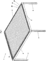
- the Figure 1 shows a perspective view of a canopy 1 according to the invention.
- the canopy 1 has four supports 1, 2, 3, 4, which form a frame of the canopy 1.
- a plurality of slats 10, 20, 30 are pivotably mounted on the supports 1 and 2.
- the slats 10, 20, 30 are inclined with respect to their longitudinal extent by 15 ° with respect to the horizontal.
- the slats 10, 20, 30 are pivoted 90 ° relative to the closed position of the slats 10, 20, 30 in the direction of the open position of the slats 10, 20, 30,
- the slats 10, 20, 30 are automatically rotated several times before the slats 10, 20, 30 are pivoted into the open position by an acute angle of 30 ° from the closed position pivoted in the direction of rotation to the open position into a draining position and after each pivoting into the draining position, pivoted back again in the direction of rotation to the closing position after the slats 10, 20, 30 were held in the draining position for several seconds.
- the beams 1, 2, 3, 4 are in accordance with three vertical posts 5, 6, 7 and another in perspective Fig. 1 Invisible post on the corners between the beams 1, 2, 3, 4 worn.
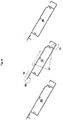
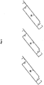
- the Figure 2 shows a perspective view of the three slats according to Figure 1 , namely a first lamella 10, an adjacent lamella 20 and a further lamella 30.
- the lamellae 10, 20, 30 each have a longitudinal extent 55.
- the Figure 3 shows a cross section of the slats Figure 2 in the closed position, in which the slats 10, 20, 30 form a closed roof surface.
- the lamellae 10, 20, 30 are each designed as hollow chamber profiles.
- the slats 10, 20, 30 are also pivoted out of their closed position in the direction of arrow 50 in the image plane in a clockwise direction in the direction of rotation to the open position.
- the slats 10, 20, 30 thus each have a downwardly pivoting part 11, 21, 31, each of which has a drainage channel 15, 25, 35.
- the slats 10, 20, 30 each have a part 12, 22, 32 which swings upwards.
- the Figure 4 shows a cross section of the slats 10, 20, 30 to Figure 3 in a draining position in which the slats 10, 20, 30 are pivoted by 30 ° with respect to the closed position in the direction of the open position according to arrow 50.
- the parts 11, 21, 31 which pivot downward are each geodetically below the parts 12, 22, 32 which pivot upwards the water 51 collected on the fins 10, 20, 30 can run off into the drainage channels 15, 25, 35 of the fins 10, 20, 30.
- the slats 10, 20, 30 are also inclined with respect to their longitudinal extent with respect to the horizontal, the water 51 runs out of the drainage channels 15; 25, 35 to the side so that the space under the canopy is not contaminated.
- the Figure 5 shows a cross section of the slats Figure 3 in a first open position, in which the slats 10, 20, 30 are pivoted by 90 ° with respect to the closed position.
- the Figure 6 shows a cross section of the slats Figure 3 in a second open position, in which the slats 10, 20, 30 are pivoted by 140 ° with respect to the closed position.
- Such a roof 1 prevents the slats 10, 20, 30 from pivoting into the open position Figure 5 or 6 the precipitation and / or dirt on the lamellae 10, 20, 30 reaches the space under the canopy 1 and thereby contaminates the space.
- This is done in that the slats 10, 20, 30 automatically by means of the drive before the slats 10, 20, 30 are pivoted into the open position several times, at an angle of 30 ° from the closed position Figure 3 in the direction of rotation to the open position into the draining position Figure 4 are pivoted and, after each pivoting into the draining position, are pivoted back again in the direction of rotation to the closed position after the slats 10, 20, 30 have been held in the draining position for several seconds.
- the precipitation and / or dirt flows from the fins 10, 20, 30 into the drainage channels 15, 25, 35 and due to the inclination of the fins 10, 20, 30 to the side to the horizontal.
Landscapes
- Engineering & Computer Science (AREA)
- Architecture (AREA)
- Civil Engineering (AREA)
- Structural Engineering (AREA)
- Building Environments (AREA)
Priority Applications (1)
| Application Number | Priority Date | Filing Date | Title |
|---|---|---|---|
| EP18000941.7A EP3663480B1 (fr) | 2018-12-06 | 2018-12-06 | Toit à lamelles pourvu de pare-gouttes |
Applications Claiming Priority (1)
| Application Number | Priority Date | Filing Date | Title |
|---|---|---|---|
| EP18000941.7A EP3663480B1 (fr) | 2018-12-06 | 2018-12-06 | Toit à lamelles pourvu de pare-gouttes |
Publications (2)
| Publication Number | Publication Date |
|---|---|
| EP3663480A1 true EP3663480A1 (fr) | 2020-06-10 |
| EP3663480B1 EP3663480B1 (fr) | 2021-09-22 |
Family
ID=64661041
Family Applications (1)
| Application Number | Title | Priority Date | Filing Date |
|---|---|---|---|
| EP18000941.7A Active EP3663480B1 (fr) | 2018-12-06 | 2018-12-06 | Toit à lamelles pourvu de pare-gouttes |
Country Status (1)
| Country | Link |
|---|---|
| EP (1) | EP3663480B1 (fr) |
Cited By (4)
| Publication number | Priority date | Publication date | Assignee | Title |
|---|---|---|---|---|
| CN115306185A (zh) * | 2022-09-02 | 2022-11-08 | 佛山优格朗装饰材料科技有限公司 | 一种翻板叶片、遮阳组件和百叶凉亭 |
| EP4324996A1 (fr) | 2022-08-15 | 2024-02-21 | Weinor GmbH & Co. KG | Toit à lamelles avec évacuation des eaux de pluie par les lamelles |
| PL444887A1 (pl) * | 2023-05-12 | 2024-11-18 | Piechowski Sylwester Sun Winner Group | System domykający zadaszenie pergoli ogrodowych |
| US20240384531A1 (en) * | 2021-08-30 | 2024-11-21 | Renson Outdoor | Slatted roof, terrace canopy comprising the same, and a kit of parts and a method for assembling the same |
Families Citing this family (2)
| Publication number | Priority date | Publication date | Assignee | Title |
|---|---|---|---|---|
| IT202200023712A1 (it) * | 2022-11-17 | 2024-05-17 | Pratic F Lli Orioli S P A | Organo di filtraggio per un apparato di copertura |
| CN219080804U (zh) * | 2023-01-10 | 2023-05-26 | 东莞市阿鲁诺建材有限公司 | 一种可隐藏排水的遮阳棚 |
Citations (4)
| Publication number | Priority date | Publication date | Assignee | Title |
|---|---|---|---|---|
| DE9110964U1 (de) * | 1990-09-28 | 1991-10-31 | E.M.B. Metallbau und Brandschutztechnik GmbH, 4240 Emmerich | Lamellenlüfter für Gebäudedächer |
| EP3196379A1 (fr) * | 2015-12-29 | 2017-07-26 | Teleco Automation S.R.L. | Infrastructure pour le contrôle et le déplacement d'une fermeture à lames d'une pergola ou d'un dispositif similaire |
| DE102016117772A1 (de) * | 2016-09-21 | 2018-03-22 | Jürgen Grimmeisen | Rahmenkonstruktion mit Eckverbinder |
| US20180100310A1 (en) * | 2016-10-03 | 2018-04-12 | Helmut Sprotofski | Louver Drive System |
-
2018
- 2018-12-06 EP EP18000941.7A patent/EP3663480B1/fr active Active
Patent Citations (4)
| Publication number | Priority date | Publication date | Assignee | Title |
|---|---|---|---|---|
| DE9110964U1 (de) * | 1990-09-28 | 1991-10-31 | E.M.B. Metallbau und Brandschutztechnik GmbH, 4240 Emmerich | Lamellenlüfter für Gebäudedächer |
| EP3196379A1 (fr) * | 2015-12-29 | 2017-07-26 | Teleco Automation S.R.L. | Infrastructure pour le contrôle et le déplacement d'une fermeture à lames d'une pergola ou d'un dispositif similaire |
| DE102016117772A1 (de) * | 2016-09-21 | 2018-03-22 | Jürgen Grimmeisen | Rahmenkonstruktion mit Eckverbinder |
| US20180100310A1 (en) * | 2016-10-03 | 2018-04-12 | Helmut Sprotofski | Louver Drive System |
Cited By (4)
| Publication number | Priority date | Publication date | Assignee | Title |
|---|---|---|---|---|
| US20240384531A1 (en) * | 2021-08-30 | 2024-11-21 | Renson Outdoor | Slatted roof, terrace canopy comprising the same, and a kit of parts and a method for assembling the same |
| EP4324996A1 (fr) | 2022-08-15 | 2024-02-21 | Weinor GmbH & Co. KG | Toit à lamelles avec évacuation des eaux de pluie par les lamelles |
| CN115306185A (zh) * | 2022-09-02 | 2022-11-08 | 佛山优格朗装饰材料科技有限公司 | 一种翻板叶片、遮阳组件和百叶凉亭 |
| PL444887A1 (pl) * | 2023-05-12 | 2024-11-18 | Piechowski Sylwester Sun Winner Group | System domykający zadaszenie pergoli ogrodowych |
Also Published As
| Publication number | Publication date |
|---|---|
| EP3663480B1 (fr) | 2021-09-22 |
Similar Documents
| Publication | Publication Date | Title |
|---|---|---|
| EP3663480B1 (fr) | Toit à lamelles pourvu de pare-gouttes | |
| EP4324996B1 (fr) | Toit à lamelles avec évacuation des eaux de pluie par les lamelles | |
| EP0982466B1 (fr) | Store à rouleau | |
| EP4123901A1 (fr) | Système de montage et procédé de montage des modules photovoltaïques encadrés | |
| DE202016102741U1 (de) | Mobiles Gewächshaus mit einem Rahmenwerk | |
| DE2915260A1 (de) | Verfahren und einrichtung zum belueften von viehstaellen | |
| EP3587698B1 (fr) | Toit à lamelles | |
| EP3444412B1 (fr) | Toit de terrasse avec éléments de toit fixes et lamelles mobiles | |
| DE9110964U1 (de) | Lamellenlüfter für Gebäudedächer | |
| DE19520419C2 (de) | Befestigungsvorrichtung für Balkonverkleidungselemente | |
| DE102018109985A1 (de) | Verschlussvorrichtung mit Leitschaufel | |
| EP3421682B1 (fr) | Store pourvu d'évacuation d'eau | |
| EP2614706B1 (fr) | Construction de faîtière | |
| EP2698485B1 (fr) | Agencement de fenêtre de toit | |
| EP4141191A1 (fr) | Toit à lamelles pourvu de lamelles mobiles à entrainement par courroie | |
| DE2416417A1 (de) | Regulierbare belueftungseinrichtung | |
| WO2021044051A1 (fr) | Dispositif comprenant un élément de type nasse pivotant | |
| EP3088292A1 (fr) | Construction de paroi exterieure pur cabines de bateaux | |
| DE29824480U1 (de) | Wickeljalousie | |
| DE20306015U1 (de) | Firsthaube und Firstabdeckung hieraus | |
| EP1681431B1 (fr) | Volet roulant pour fenêtre de toiture | |
| DE102004027933B3 (de) | Lamellenfenster | |
| EP4357580A1 (fr) | Gargouille pour la déshydratation d'une rigole dans la zone d'un élément mural d'un bâtiment | |
| DE9013622U1 (de) | Lamellenlüfter für Gebäudedächer | |
| DE3216113C2 (de) | Belüftungseinrichtung für Kaltdächer |
Legal Events
| Date | Code | Title | Description |
|---|---|---|---|
| PUAI | Public reference made under article 153(3) epc to a published international application that has entered the european phase |
Free format text: ORIGINAL CODE: 0009012 |
|
| STAA | Information on the status of an ep patent application or granted ep patent |
Free format text: STATUS: THE APPLICATION HAS BEEN PUBLISHED |
|
| AK | Designated contracting states |
Kind code of ref document: A1 Designated state(s): AL AT BE BG CH CY CZ DE DK EE ES FI FR GB GR HR HU IE IS IT LI LT LU LV MC MK MT NL NO PL PT RO RS SE SI SK SM TR |
|
| AX | Request for extension of the european patent |
Extension state: BA ME |
|
| STAA | Information on the status of an ep patent application or granted ep patent |
Free format text: STATUS: REQUEST FOR EXAMINATION WAS MADE |
|
| 17P | Request for examination filed |
Effective date: 20201207 |
|
| RBV | Designated contracting states (corrected) |
Designated state(s): AL AT BE BG CH CY CZ DE DK EE ES FI FR GB GR HR HU IE IS IT LI LT LU LV MC MK MT NL NO PL PT RO RS SE SI SK SM TR |
|
| GRAP | Despatch of communication of intention to grant a patent |
Free format text: ORIGINAL CODE: EPIDOSNIGR1 |
|
| STAA | Information on the status of an ep patent application or granted ep patent |
Free format text: STATUS: GRANT OF PATENT IS INTENDED |
|
| RIC1 | Information provided on ipc code assigned before grant |
Ipc: E04F 10/10 20060101AFI20210420BHEP |
|
| INTG | Intention to grant announced |
Effective date: 20210506 |
|
| RIN1 | Information on inventor provided before grant (corrected) |
Inventor name: STAWSKI, KARL-HEINZ |
|
| GRAS | Grant fee paid |
Free format text: ORIGINAL CODE: EPIDOSNIGR3 |
|
| GRAA | (expected) grant |
Free format text: ORIGINAL CODE: 0009210 |
|
| STAA | Information on the status of an ep patent application or granted ep patent |
Free format text: STATUS: THE PATENT HAS BEEN GRANTED |
|
| AK | Designated contracting states |
Kind code of ref document: B1 Designated state(s): AL AT BE BG CH CY CZ DE DK EE ES FI FR GB GR HR HU IE IS IT LI LT LU LV MC MK MT NL NO PL PT RO RS SE SI SK SM TR |
|
| REG | Reference to a national code |
Ref country code: GB Ref legal event code: FG4D Free format text: NOT ENGLISH |
|
| REG | Reference to a national code |
Ref country code: IE Ref legal event code: FG4D Free format text: LANGUAGE OF EP DOCUMENT: GERMAN |
|
| REG | Reference to a national code |
Ref country code: DE Ref legal event code: R096 Ref document number: 502018007127 Country of ref document: DE |
|
| REG | Reference to a national code |
Ref country code: CH Ref legal event code: EP Ref country code: AT Ref legal event code: REF Ref document number: 1432445 Country of ref document: AT Kind code of ref document: T Effective date: 20211015 |
|
| REG | Reference to a national code |
Ref country code: NL Ref legal event code: FP |
|
| REG | Reference to a national code |
Ref country code: LT Ref legal event code: MG9D |
|
| PG25 | Lapsed in a contracting state [announced via postgrant information from national office to epo] |
Ref country code: RS Free format text: LAPSE BECAUSE OF FAILURE TO SUBMIT A TRANSLATION OF THE DESCRIPTION OR TO PAY THE FEE WITHIN THE PRESCRIBED TIME-LIMIT Effective date: 20210922 Ref country code: SE Free format text: LAPSE BECAUSE OF FAILURE TO SUBMIT A TRANSLATION OF THE DESCRIPTION OR TO PAY THE FEE WITHIN THE PRESCRIBED TIME-LIMIT Effective date: 20210922 Ref country code: FI Free format text: LAPSE BECAUSE OF FAILURE TO SUBMIT A TRANSLATION OF THE DESCRIPTION OR TO PAY THE FEE WITHIN THE PRESCRIBED TIME-LIMIT Effective date: 20210922 Ref country code: HR Free format text: LAPSE BECAUSE OF FAILURE TO SUBMIT A TRANSLATION OF THE DESCRIPTION OR TO PAY THE FEE WITHIN THE PRESCRIBED TIME-LIMIT Effective date: 20210922 Ref country code: BG Free format text: LAPSE BECAUSE OF FAILURE TO SUBMIT A TRANSLATION OF THE DESCRIPTION OR TO PAY THE FEE WITHIN THE PRESCRIBED TIME-LIMIT Effective date: 20211222 Ref country code: LT Free format text: LAPSE BECAUSE OF FAILURE TO SUBMIT A TRANSLATION OF THE DESCRIPTION OR TO PAY THE FEE WITHIN THE PRESCRIBED TIME-LIMIT Effective date: 20210922 Ref country code: NO Free format text: LAPSE BECAUSE OF FAILURE TO SUBMIT A TRANSLATION OF THE DESCRIPTION OR TO PAY THE FEE WITHIN THE PRESCRIBED TIME-LIMIT Effective date: 20211222 |
|
| PG25 | Lapsed in a contracting state [announced via postgrant information from national office to epo] |
Ref country code: LV Free format text: LAPSE BECAUSE OF FAILURE TO SUBMIT A TRANSLATION OF THE DESCRIPTION OR TO PAY THE FEE WITHIN THE PRESCRIBED TIME-LIMIT Effective date: 20210922 Ref country code: GR Free format text: LAPSE BECAUSE OF FAILURE TO SUBMIT A TRANSLATION OF THE DESCRIPTION OR TO PAY THE FEE WITHIN THE PRESCRIBED TIME-LIMIT Effective date: 20211223 |
|
| PG25 | Lapsed in a contracting state [announced via postgrant information from national office to epo] |
Ref country code: IS Free format text: LAPSE BECAUSE OF FAILURE TO SUBMIT A TRANSLATION OF THE DESCRIPTION OR TO PAY THE FEE WITHIN THE PRESCRIBED TIME-LIMIT Effective date: 20220122 Ref country code: SK Free format text: LAPSE BECAUSE OF FAILURE TO SUBMIT A TRANSLATION OF THE DESCRIPTION OR TO PAY THE FEE WITHIN THE PRESCRIBED TIME-LIMIT Effective date: 20210922 Ref country code: RO Free format text: LAPSE BECAUSE OF FAILURE TO SUBMIT A TRANSLATION OF THE DESCRIPTION OR TO PAY THE FEE WITHIN THE PRESCRIBED TIME-LIMIT Effective date: 20210922 Ref country code: PT Free format text: LAPSE BECAUSE OF FAILURE TO SUBMIT A TRANSLATION OF THE DESCRIPTION OR TO PAY THE FEE WITHIN THE PRESCRIBED TIME-LIMIT Effective date: 20220124 Ref country code: PL Free format text: LAPSE BECAUSE OF FAILURE TO SUBMIT A TRANSLATION OF THE DESCRIPTION OR TO PAY THE FEE WITHIN THE PRESCRIBED TIME-LIMIT Effective date: 20210922 Ref country code: ES Free format text: LAPSE BECAUSE OF FAILURE TO SUBMIT A TRANSLATION OF THE DESCRIPTION OR TO PAY THE FEE WITHIN THE PRESCRIBED TIME-LIMIT Effective date: 20210922 Ref country code: EE Free format text: LAPSE BECAUSE OF FAILURE TO SUBMIT A TRANSLATION OF THE DESCRIPTION OR TO PAY THE FEE WITHIN THE PRESCRIBED TIME-LIMIT Effective date: 20210922 Ref country code: CZ Free format text: LAPSE BECAUSE OF FAILURE TO SUBMIT A TRANSLATION OF THE DESCRIPTION OR TO PAY THE FEE WITHIN THE PRESCRIBED TIME-LIMIT Effective date: 20210922 Ref country code: AL Free format text: LAPSE BECAUSE OF FAILURE TO SUBMIT A TRANSLATION OF THE DESCRIPTION OR TO PAY THE FEE WITHIN THE PRESCRIBED TIME-LIMIT Effective date: 20210922 |
|
| REG | Reference to a national code |
Ref country code: DE Ref legal event code: R097 Ref document number: 502018007127 Country of ref document: DE |
|
| PG25 | Lapsed in a contracting state [announced via postgrant information from national office to epo] |
Ref country code: MC Free format text: LAPSE BECAUSE OF FAILURE TO SUBMIT A TRANSLATION OF THE DESCRIPTION OR TO PAY THE FEE WITHIN THE PRESCRIBED TIME-LIMIT Effective date: 20210922 Ref country code: DK Free format text: LAPSE BECAUSE OF FAILURE TO SUBMIT A TRANSLATION OF THE DESCRIPTION OR TO PAY THE FEE WITHIN THE PRESCRIBED TIME-LIMIT Effective date: 20210922 |
|
| PLBE | No opposition filed within time limit |
Free format text: ORIGINAL CODE: 0009261 |
|
| STAA | Information on the status of an ep patent application or granted ep patent |
Free format text: STATUS: NO OPPOSITION FILED WITHIN TIME LIMIT |
|
| 26N | No opposition filed |
Effective date: 20220623 |
|
| PG25 | Lapsed in a contracting state [announced via postgrant information from national office to epo] |
Ref country code: LU Free format text: LAPSE BECAUSE OF NON-PAYMENT OF DUE FEES Effective date: 20211206 Ref country code: IE Free format text: LAPSE BECAUSE OF NON-PAYMENT OF DUE FEES Effective date: 20211206 |
|
| PG25 | Lapsed in a contracting state [announced via postgrant information from national office to epo] |
Ref country code: SI Free format text: LAPSE BECAUSE OF FAILURE TO SUBMIT A TRANSLATION OF THE DESCRIPTION OR TO PAY THE FEE WITHIN THE PRESCRIBED TIME-LIMIT Effective date: 20210922 |
|
| REG | Reference to a national code |
Ref country code: DE Ref legal event code: R082 Ref document number: 502018007127 Country of ref document: DE Representative=s name: PATENTANWALTSKANZLEI METHLING DR. FRANK-OLIVER, DE Ref country code: DE Ref legal event code: R082 Ref document number: 502018007127 Country of ref document: DE Representative=s name: KUTZENBERGER WOLFF & PARTNER PATENTANWALTSPART, DE Ref country code: DE Ref legal event code: R082 Ref document number: 502018007127 Country of ref document: DE Representative=s name: METHLING, FRANK-OLIVER, DIPL.-ING. DR.-ING., DE |
|
| PG25 | Lapsed in a contracting state [announced via postgrant information from national office to epo] |
Ref country code: CY Free format text: LAPSE BECAUSE OF FAILURE TO SUBMIT A TRANSLATION OF THE DESCRIPTION OR TO PAY THE FEE WITHIN THE PRESCRIBED TIME-LIMIT Effective date: 20210922 |
|
| PG25 | Lapsed in a contracting state [announced via postgrant information from national office to epo] |
Ref country code: SM Free format text: LAPSE BECAUSE OF FAILURE TO SUBMIT A TRANSLATION OF THE DESCRIPTION OR TO PAY THE FEE WITHIN THE PRESCRIBED TIME-LIMIT Effective date: 20210922 Ref country code: HU Free format text: LAPSE BECAUSE OF FAILURE TO SUBMIT A TRANSLATION OF THE DESCRIPTION OR TO PAY THE FEE WITHIN THE PRESCRIBED TIME-LIMIT; INVALID AB INITIO Effective date: 20181206 |
|
| PGFP | Annual fee paid to national office [announced via postgrant information from national office to epo] |
Ref country code: GB Payment date: 20231220 Year of fee payment: 6 |
|
| PGFP | Annual fee paid to national office [announced via postgrant information from national office to epo] |
Ref country code: NL Payment date: 20231219 Year of fee payment: 6 Ref country code: FR Payment date: 20231220 Year of fee payment: 6 Ref country code: AT Payment date: 20231214 Year of fee payment: 6 |
|
| PGFP | Annual fee paid to national office [announced via postgrant information from national office to epo] |
Ref country code: BE Payment date: 20231218 Year of fee payment: 6 |
|
| PG25 | Lapsed in a contracting state [announced via postgrant information from national office to epo] |
Ref country code: MK Free format text: LAPSE BECAUSE OF FAILURE TO SUBMIT A TRANSLATION OF THE DESCRIPTION OR TO PAY THE FEE WITHIN THE PRESCRIBED TIME-LIMIT Effective date: 20210922 |
|
| PGFP | Annual fee paid to national office [announced via postgrant information from national office to epo] |
Ref country code: CH Payment date: 20240110 Year of fee payment: 6 |
|
| PGFP | Annual fee paid to national office [announced via postgrant information from national office to epo] |
Ref country code: IT Payment date: 20231229 Year of fee payment: 6 |
|
| PG25 | Lapsed in a contracting state [announced via postgrant information from national office to epo] |
Ref country code: MT Free format text: LAPSE BECAUSE OF FAILURE TO SUBMIT A TRANSLATION OF THE DESCRIPTION OR TO PAY THE FEE WITHIN THE PRESCRIBED TIME-LIMIT Effective date: 20210922 |
|
| PGFP | Annual fee paid to national office [announced via postgrant information from national office to epo] |
Ref country code: DE Payment date: 20241231 Year of fee payment: 7 |
|
| REG | Reference to a national code |
Ref country code: DE Ref legal event code: R082 Ref document number: 502018007127 Country of ref document: DE Representative=s name: KUTZENBERGER WOLFF & PARTNER PATENTANWALTSPART, DE Ref country code: DE Ref legal event code: R082 Ref document number: 502018007127 Country of ref document: DE Representative=s name: METHLING, FRANK-OLIVER, DIPL.-ING. DR.-ING., DE |
|
| REG | Reference to a national code |
Ref country code: DE Ref legal event code: R082 Ref document number: 502018007127 Country of ref document: DE Representative=s name: KUTZENBERGER WOLFF & PARTNER PATENTANWALTSPART, DE |
|
| REG | Reference to a national code |
Ref country code: CH Ref legal event code: PL |
|
| REG | Reference to a national code |
Ref country code: NL Ref legal event code: MM Effective date: 20250101 |
|
| REG | Reference to a national code |
Ref country code: AT Ref legal event code: MM01 Ref document number: 1432445 Country of ref document: AT Kind code of ref document: T Effective date: 20241206 |
|
| GBPC | Gb: european patent ceased through non-payment of renewal fee |
Effective date: 20241206 |
|
| PG25 | Lapsed in a contracting state [announced via postgrant information from national office to epo] |
Ref country code: NL Free format text: LAPSE BECAUSE OF NON-PAYMENT OF DUE FEES Effective date: 20250101 |
|
| REG | Reference to a national code |
Ref country code: BE Ref legal event code: MM Effective date: 20241231 |
|
| PG25 | Lapsed in a contracting state [announced via postgrant information from national office to epo] |
Ref country code: IT Free format text: LAPSE BECAUSE OF NON-PAYMENT OF DUE FEES Effective date: 20241206 |
|
| PG25 | Lapsed in a contracting state [announced via postgrant information from national office to epo] |
Ref country code: GB Free format text: LAPSE BECAUSE OF NON-PAYMENT OF DUE FEES Effective date: 20241206 Ref country code: BE Free format text: LAPSE BECAUSE OF NON-PAYMENT OF DUE FEES Effective date: 20241231 |
|
| PG25 | Lapsed in a contracting state [announced via postgrant information from national office to epo] |
Ref country code: FR Free format text: LAPSE BECAUSE OF NON-PAYMENT OF DUE FEES Effective date: 20241231 Ref country code: AT Free format text: LAPSE BECAUSE OF NON-PAYMENT OF DUE FEES Effective date: 20241206 |
|
| PG25 | Lapsed in a contracting state [announced via postgrant information from national office to epo] |
Ref country code: CH Free format text: LAPSE BECAUSE OF NON-PAYMENT OF DUE FEES Effective date: 20241231 |
|
| PG25 | Lapsed in a contracting state [announced via postgrant information from national office to epo] |
Ref country code: TR Free format text: LAPSE BECAUSE OF FAILURE TO SUBMIT A TRANSLATION OF THE DESCRIPTION OR TO PAY THE FEE WITHIN THE PRESCRIBED TIME-LIMIT Effective date: 20210922 |