EP1431707A1 - Procédé et dispositif pour l'acquisition, au moyen d'un capteur optoélectronique, d'objets placés sur un convoyeur - Google Patents
Procédé et dispositif pour l'acquisition, au moyen d'un capteur optoélectronique, d'objets placés sur un convoyeur Download PDFInfo
- Publication number
- EP1431707A1 EP1431707A1 EP03026260A EP03026260A EP1431707A1 EP 1431707 A1 EP1431707 A1 EP 1431707A1 EP 03026260 A EP03026260 A EP 03026260A EP 03026260 A EP03026260 A EP 03026260A EP 1431707 A1 EP1431707 A1 EP 1431707A1
- Authority
- EP
- European Patent Office
- Prior art keywords
- objects
- conveyor
- optoelectronic sensor
- dimensions
- funding
- Prior art date
- Legal status (The legal status is an assumption and is not a legal conclusion. Google has not performed a legal analysis and makes no representation as to the accuracy of the status listed.)
- Granted
Links
- 230000005693 optoelectronics Effects 0.000 title claims abstract description 62
- 238000000034 method Methods 0.000 title claims abstract description 41
- 230000005484 gravity Effects 0.000 claims abstract description 22
- 238000012545 processing Methods 0.000 claims description 16
- 238000011156 evaluation Methods 0.000 claims description 15
- 238000001514 detection method Methods 0.000 claims description 13
- 238000005259 measurement Methods 0.000 claims description 7
- 238000012937 correction Methods 0.000 claims description 3
- 230000004888 barrier function Effects 0.000 claims description 2
- 230000003111 delayed effect Effects 0.000 description 2
- 230000001360 synchronised effect Effects 0.000 description 2
- 239000003086 colorant Substances 0.000 description 1
- 230000001419 dependent effect Effects 0.000 description 1
- 238000013507 mapping Methods 0.000 description 1
- 239000000463 material Substances 0.000 description 1
- 238000012360 testing method Methods 0.000 description 1
- 238000012549 training Methods 0.000 description 1
- 238000012795 verification Methods 0.000 description 1
Images


Classifications
-
- G—PHYSICS
- G01—MEASURING; TESTING
- G01B—MEASURING LENGTH, THICKNESS OR SIMILAR LINEAR DIMENSIONS; MEASURING ANGLES; MEASURING AREAS; MEASURING IRREGULARITIES OF SURFACES OR CONTOURS
- G01B11/00—Measuring arrangements characterised by the use of optical techniques
- G01B11/02—Measuring arrangements characterised by the use of optical techniques for measuring length, width or thickness
- G01B11/04—Measuring arrangements characterised by the use of optical techniques for measuring length, width or thickness specially adapted for measuring length or width of objects while moving
Definitions
- the invention relates to a method for detecting on a segmented Funding moving objects and a method of determination the dimensions of objects moving on a conveyor, each by means of an optoelectronic sensor.
- the invention relates to devices for performing the above Method.
- the dimensions from on a segmented or an unsegmented funding moving objects determined by means of an optoelectronic sensor it is problematic that the funding often comes with mechanical tolerances, which then leads to a falsification of the Lead measurement result.
- the surface of the funding can with different objects to be measured on different Absolute heights are located, so that the objects are each of the same height due to the different absolute heights of the funding surface different object heights are incorrectly determined.
- a further disadvantage of known systems is that in the context of Determination of the dimensions of the conveyed objects often only be scanned in the area with which they are in the area of a funding segment. Object parts that have a conveyor segment protruding are not recorded, which ultimately leads to incorrect Object dimensions can be determined.
- the first-mentioned object is achieved according to a first variant of the invention by a method according to claim 1 and in particular by a method for recording on a segmented funding resolved moving objects by means of an optoelectronic sensor, at the geometrical one via the optoelectronic sensor
- the focus of the objects is determined, whereupon the objects each be assigned to the funding segment in whose area the each has a certain geometric center of gravity.
- An inventive device for performing this method includes a segmented funding and an optoelectronic Sensor, which with an evaluation unit for determining the geometric The objects' focus is coupled, with an assignment unit to assign the objects to that conveyor segment, in whose area is the particular focus is.
- the second object is achieved according to a second variant of the invention by the features of claim 10 and in particular by a method for determining the dimensions of on a Funds moving objects using an optoelectronic sensor solved, in which the dimensions of the objects are recorded and corresponding, object-related values are supplied, and in which the optoelectronic Sensor also the dimensions of the conveyor recorded and provides corresponding, funding-related values, whereby by offsetting the property-related values with the funding-related Values of funding tolerances and / or between object and Any existing voids can be compensated for.
- An inventive device for performing this method includes funding and an optoelectronic sensor for detection the dimensions of the objects and to provide appropriate object-related values, the optoelectronic sensor for additional recording of the dimensions of the funding and Provision of appropriate funding-related values is designed, and wherein a compensation unit for compensation of funding tolerances and / or between the object and the funding, if any Cavities is provided.
- the first-mentioned variant according to the invention is made known take advantage of the fact that the geometric focus of an object is in the Usually located in the area of the funding segment assigned to it, independently whether parts of the object protrude beyond the conveyor segment or not.
- the center of gravity of the respective object is located with a very high probability a correct assignment between Achieve object and conveyor segment.
- the geometric center of gravity can basically be based on the captured actual object footprint, the captured projected Object base area or the detected object volume can be determined.
- one is through the optoelectronic Distance measurement by sensor is not absolutely necessary, whereas such a distance measurement to determine the object volume is needed.
- each generated a trigger signal becomes. Whether a trigger signal is assigned to a conveyor segment or not, for example manually, through a loading process supervisory person can be decided. Alternatively, such Trigger signal also automatically from a higher-level control unit are generated, which the loading process of the funding controls or monitors and which is accordingly known whether a a specific conveyor segment was loaded with an object.
- a trigger signal of the type mentioned preferably marks the beginning and the end of each conveyor segment loaded with an object, where the duration of the trigger signal preferably the one running in the conveying direction Corresponds to the length of a conveyor segment.
- a short start and end of each fed segment Single trigger signal can be assigned, with the single trigger signals distinguish between the beginning and end of the conveyor segment.
- a trigger signal that lasts the entire length of a conveyor segment can, for example, always be generated in that time interval be in which a conveyor segment loaded with an object the Detection range of an optoelectronic provided according to the invention Sensor goes through.
- the optoelectronic Sensor or an evaluation or data processing unit communicated in what period of time the optoelectronic sensor is a with a Object scanned conveyor segment and in what period the optoelectronic sensor the space between two successive Conveyor segments or one not loaded with an object Scans conveyor segment. This way you can easily get one on the respective position-related relative assignment between object and conveyor segment take place, which is synonymous with the fact that an evaluation or data processing unit can be communicated where exactly Object parts on a conveyor segment or between two successive ones Conveyor segments.
- an assignment signal can then be synchronous with a time or path delay to the trigger signal an assignment signal are output.
- An output of a mapping signal during or exactly at the end of a trigger signal is according to the invention not possible because the objects over the end of a conveyor segment can protrude and thus the complete recording such objects only after the trigger signal has ended, ie after the relevant conveyor segment the detection area of the optoelectronic Sensor has left, can be completed.
- One in comparison Delayed output of an assignment signal to the trigger signal is possible if the conveyor segments move at a constant speed move or if the delay period is dependent variably set by the speed of the conveyor segments becomes.
- a delayed output of the assignment signal is offered then when the conveyor segments with a position encoder, for example a rotary encoder are coupled, which one the output of Assignment signal triggering control unit each tells how far the conveyor segments each from the detection area of the optoelectronic Sensors have moved away.
- a position encoder for example a rotary encoder
- the method according to the invention can be particularly advantageously according to the first variant, if one is on an object Element, in particular a code, a barcode or an address label recorded and assigned to an object.
- an object Element in particular a code, a barcode or an address label recorded and assigned to an object.
- a detected element is always assigned to that object be whose geometric focus or parallel to Conveying plane running contour is closest to the detected element. This ensures that the detected element is assigned to the respective associated object, where it is of course necessary to do this for the relative position of the detected element to determine the detected object or its geometric center of gravity.
- the second variant of the invention it is possible to measure the dimensions of objects moving on a conveyor exactly.
- This exact determination of the dimensions is possible according to the invention, because by means of the optoelectronic sensor not only the dimensions of the objects but also the dimensions of the funding be recorded. In this way, for example, funding tolerances determined quantitatively and when calculating the dimensions of objects are taken into account.
- the varying distance determined between the conveyor segments and the optoelectronic sensor so that when determining the dimensions of the objects clear a distinction can be made, for example, whether an object is higher than a is different or whether a supposedly higher object is only on one increased funding segment.
- the described compensation of funding tolerances can in the example described by a simple Subtraction of the determined fluctuation in distance between conveyor segments and optoelectronic sensor from the object-related Distance values can be realized.
- the dimensions of the funding and / or objects in all three dimensions be recorded. In this way, for example, a correct volume calculation of the detected objects possible.
- Target dimensions of the funding are saved and with the recorded Actual dimensions of the funding are compared, the result this comparison is used as a correction value for compensation.
- the actual dimensions of the conveying means can, for example, thereby be determined that the funding free of objects by the Detection area of the optoelectronic sensor is moved.
- the target dimensions of the funding can be fixed as numerical values be specified.
- the objects of the optoelectronic sensor continuously over its entire length Direction of conveying length and / or across their entire, transversely width extending to the conveying direction are recorded. If both The length as well as the width of the objects are completely captured, in particular correct volume calculation possible and also the probability for a correct assignment between objects and conveyor segments gets so high.
- the two variants according to the invention can also be combined with one another combine, especially any combination of each described preferred embodiments of both inventive Variants possible.
- Variants can be achieved when transporting Objects on segmented funding on the one hand a correct assignment between objects and funding is ensured and at the same time a very precise determination of the dimensions of the detected Objects.
- the above-mentioned devices for performing the two Variants according to the invention can each have an evaluation or Data processing unit are provided or coupled, such is designed such that one or more of the preferred described Process variants can be realized. If both of the invention Variants on a single device simultaneously and together Of course, it is possible to implement only one use only data processing unit, all of the invention Procedure implemented.
- the optoelectronic sensor used according to the invention can, for example designed as a light barrier, as a scanner or as a camera be, in particular it is carried out so that it is not only for Detection of an object, but also for determination of distances. It is particularly preferred if the optoelectronic sensor as a laser scanner with transverse or oblique to the conveying direction extending scanning direction is formed.
- the optoelectronic sensor or an evaluation or coupled to it Data processing unit can be used for code recognition and / or image processing be designed to additionally recognize special, to allow elements on the object, such as barcodes.
- the funding used according to the invention can, for example as a conveyor belt, tray conveyor, tray conveyor or as Crossbelt promoters are trained.
- Fig. 1 shows a perspective view of a funding, which individual conveyor segments that follow one another in the direction of conveyance (arrow) 1 to 4 exists.
- the conveyor segments 1 to 4 are shown schematically in Fig. 1 as square plate elements shown, in practice they can Conveyor segments 1 to 4, for example, as tubs or trays be executed.
- the entire funding to train as a cross belt conveyor, in which each individual conveyor segment 1 to 4 has another, own funding, which one Has transport transversely to the actual conveying direction of the conveying means, so the loading of the funding or the removal of objects from the conveyor line.
- the Object 5 is located on the conveyor segments with similarly large areas 1 and 2 and thus extends over the between them two conveyor segments 1 and 2 located space, wherein however, the area lying on the conveyor segment 1 is slight is larger than the area lying on the conveyor segment 2.
- the Object 6 is located entirely on conveyor segment 3.
- Object 7 is located with its larger area on the conveyor segment 4 and with its smaller area on conveyor segment 3, so that too this object 7 is located between the conveyor segments 3 and 4 Gap covered.
- an optoelectronic sensor 8 which acts as a laser scanner is carried out with a scanning direction transverse to the conveying direction.
- the opening angle of the scanning beam is so large that at least the entire width of the conveyor, but preferably one even larger area that can be captured. With a correspondingly large Training the scanning angle ensures that even very large Objects and in particular also those that move laterally over the conveyor segments 1 to 4 protrude, can be fully recorded.
- the optoelectronic sensor 8 is coupled to an evaluation or Data processing unit 9, in which the optoelectronic sensor 8 delivered signals and the trigger signal explained below are processed.
- the optoelectronic sensor Sensor 8 only off when a trigger signal is present. in the Example of Fig. 1 would accordingly the conveyor segments 4, 3 and 1 completely scanned, but not the one between the conveyor segments 1 to 4 intermediate spaces and also not the conveyor segment 2. According to the prior art, this then has the consequence that on the conveyor segment 4, only that area of the object 7 would be captured that is is on the conveyor segment 4, whereas that on the conveyor segment 3 located area of the object 7 recorded as a separate object would. So it would instead of a single object 7 on faulty Two smaller objects were detected, one of which is located on the conveyor segment 3 and another is located on the conveyor segment 4. The same would apply according to the prior art for object 5, which different areas on funding segments 1 and 2 located. As a result, according to the state of the art there is no correct verification possible whether there is an object on a Conveyor segment was placed in the area of the optoelectronic sensor 8 is actually still on this conveyor segment.
- detection is now carried out through the optoelectronic sensor 8 not only when a trigger signal is applied. Rather, there is a continuous, at no time interrupted detection of objects 5 to 7 regardless of whether they on a conveyor segment 1 to 4 or in the area between the Conveyor segments 1 to 4 formed space. There on This ensures that objects 5 to 7 are always fully recorded according to the invention in the evaluation or data processing unit 9 using a suitable method of geometric Center of gravity S of objects 5 to 7 can be determined. The fact that the Evaluation or data processing unit 9 also the trigger signal is available, the relative position of the identified focal points S can be determined for funding segments 1 to 4.
- conveyor segment 1 to 4 determine above which there is a certain geometric center of gravity S is located.
- objects 5 to are then assigned 7 to those conveyor segments 1 to 4, in the area of which geometric focus of objects 5 to 7 is located respectively.
- 1 is the geometric center of gravity of the object 5 in the area of the conveyor segment 1, the geometric focus of the object 6 in the area of the conveyor segment 3 and the geometric Center of gravity of object 7 in the area of conveyor segment 4.
- FIG. 2 shows an arrangement according to FIG. 1, here the conveyor segment 2 due to tolerances by an amount h compared to the other funding segments 1, 3, 4 is increased. This would according to the state of the art Scanning the object 6, which is on the raised conveyor segment 2 is located, lead to the object 6 one by the amount h increased height of the object 6 is determined. If in this case then the values determined by the optoelectronic sensor 8 for calculation of the volume or the dimensions of the object 6 are used would occur as a result of the elevated position of the conveyor segment 2 Error on.
- the optoelectronic sensor 8 now not only detects the object 6, but also those areas of the conveyor segment 2 that are not covered by object 6. Alternatively, the optoelectronic Sensor 8 also the empty conveyor segment 2 as part of a test run to capture.
- the evaluation or data processing unit 9 in addition to the values related to the object values related to funding segment 2 are made available so that ultimately the height position of the conveyor segment 2 is known. If the evaluation or data processing unit 9 additionally also the target height of the conveyor segment 2, the height of the corresponds to conveyor segments 1, 3, 4 which are not subject to tolerances is the deviation of the actual height of the conveyor segment 2 compared the target height and this deviation as a correction value in the calculation of the dimensions or the volume of the Object 6 are included. In this way, according to the invention the dimensions or the volume of the object 6 even then calculate correctly if the height of the conveyor segment 2 of its Target height deviates, as shown in Fig. 2.
- FIG. 3 shows an illustration according to FIG. 1 with the difference that on objects 5 to 7 each have barcodes 10 attached.
- the state of the art there is often the problem that it is not clear which one A captured barcode must be assigned to the object.
- the method known in the art is usually determined in the range which conveyor segment a barcode is located, whereupon this Barcode is then assigned to the object that is also located on the relevant conveyor segment. This can lead to errors lead if two different from each other on a conveyor segment Objects are captured or if an object is via a conveyor segment also available.
- a detected barcode 10 is always assigned to the object whose geometric center of gravity S closest to the detected barcode 10 is.
- the geometric center of gravity S and the position of the bar code 10 are determined in accordance with FIG. 3, as already explained with reference to FIG. 1.
- a clear and correct assignment of a Barcodes for an associated object 5 to 7 possible, independently whether the object 5 to 7 protrudes over a conveyor segment 1 to 4 or whether there are two objects 6, 7 within the scope of a single one Conveying segment 3 are.
- a correct assignment of the barcode 10 to object 7 is even possible if the barcode 10 is outside of the conveyor segment 4 which the object 7 is assigned according to the position of its geometric center of gravity S, since in this case too the distance between the barcode 10 and the geometric one Center of gravity S of the object 7 is less than the distance of the said Barcodes 10 from the geometric focus of the other objects 5.6.
- Fig. 4 illustrates that the inventive method even then work when two objects 6, 7 touch and accordingly there is no gap between these two objects 6, 7. It is only for the correct execution of the method according to the invention required that the optoelectronic sensor, for example, via the Determination of the geometry of the two objects 6, 7 touching one another can make a distinction between the two objects. If, for example it is known that only cuboid objects can occur in the example shown in Fig. 4 a distinction between the both objects 6, 7 already because of their different heights respectively. Alternatively, it would also be possible to use the optoelectronic Sensor 8 of each object 6, 7 has at least three corner points of it Detect surface, from which the position of objects 6, 7 can be calculated.
- the objects 6, 7 touching one another can also because of their contours, their contrast and / or their color are distinguished from one another, these parameters also being different from the optoelectronic sensor 8 can be detected.
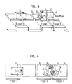
- FIG. 4 of touching one another Objects 6, 7 according to FIGS. 5 and 6 are also in such objects given that laterally offset to each other in the conveying direction Conveyor segments 1 to 4 are respectively in the direction of transport extending longitudinal overlap with each other.
- two objects 6, 7 are shown, in which the said Condition applies.
- the optoelectronic sensor 8 determined geometry, the contour, the contrast and / or the color of the Objects 6, 7 is also in the arrangements shown in FIGS. 5 and 6 objects 6 and 7 can be easily distinguished.
- FIG. 7 shows a conveyor segment designed as a bowl 11 in a sectional view with an object on it 5.
- the volume of the object 5 can be determined in the prior art the volume enclosed between object 5 and shell 11 leads 12 usually leads to a measurement error.
- the geometry of the surface of the shell 11 before the actual measurement process for example by scanning or be determined by fixed values, so that based on this Known values included between object 5 and the surface of the shell Volume 12 calculated and from that during the actual measurement process certain volume can be deducted.
- the object 5 has a flat base, otherwise a varying geometry of the base areas of on shells 11 objects 5 lying on different values with regard to the between Object 5 and shell 11 would result in enclosed volumes.
- the mathematical consideration of the enclosed volume 12 a correct determination of the object volume is possible.
Landscapes
- Physics & Mathematics (AREA)
- General Physics & Mathematics (AREA)
- Length Measuring Devices By Optical Means (AREA)
- Control Of Conveyors (AREA)
- Geophysics And Detection Of Objects (AREA)
Priority Applications (1)
| Application Number | Priority Date | Filing Date | Title |
|---|---|---|---|
| EP05023411A EP1621849A1 (fr) | 2002-12-20 | 2003-11-14 | Procédé et dispositif pour la saisie dýobjets déplacés sur une bande dýalimentation à lýaide dýun capteur optoélectronique |
Applications Claiming Priority (2)
| Application Number | Priority Date | Filing Date | Title |
|---|---|---|---|
| DE10260201A DE10260201A1 (de) | 2002-12-20 | 2002-12-20 | Verfahren und Vorrichtung zur Erfassung von auf einem Fördermittel bewegten Objekten mittels eines optoelektronischen Sensors |
| DE10260201 | 2002-12-20 |
Related Child Applications (1)
| Application Number | Title | Priority Date | Filing Date |
|---|---|---|---|
| EP05023411A Division EP1621849A1 (fr) | 2002-12-20 | 2003-11-14 | Procédé et dispositif pour la saisie dýobjets déplacés sur une bande dýalimentation à lýaide dýun capteur optoélectronique |
Publications (2)
| Publication Number | Publication Date |
|---|---|
| EP1431707A1 true EP1431707A1 (fr) | 2004-06-23 |
| EP1431707B1 EP1431707B1 (fr) | 2006-08-02 |
Family
ID=32336534
Family Applications (2)
| Application Number | Title | Priority Date | Filing Date |
|---|---|---|---|
| EP05023411A Withdrawn EP1621849A1 (fr) | 2002-12-20 | 2003-11-14 | Procédé et dispositif pour la saisie dýobjets déplacés sur une bande dýalimentation à lýaide dýun capteur optoélectronique |
| EP03026260A Expired - Lifetime EP1431707B1 (fr) | 2002-12-20 | 2003-11-14 | Procédé et dispositif pour l'acquisition, au moyen d'un capteur optoélectronique, d'objets placés sur un convoyeur |
Family Applications Before (1)
| Application Number | Title | Priority Date | Filing Date |
|---|---|---|---|
| EP05023411A Withdrawn EP1621849A1 (fr) | 2002-12-20 | 2003-11-14 | Procédé et dispositif pour la saisie dýobjets déplacés sur une bande dýalimentation à lýaide dýun capteur optoélectronique |
Country Status (6)
| Country | Link |
|---|---|
| US (1) | US7199385B2 (fr) |
| EP (2) | EP1621849A1 (fr) |
| AT (1) | ATE335186T1 (fr) |
| DE (2) | DE10260201A1 (fr) |
| DK (1) | DK1431707T3 (fr) |
| ES (1) | ES2265548T3 (fr) |
Cited By (2)
| Publication number | Priority date | Publication date | Assignee | Title |
|---|---|---|---|---|
| EP1645839A1 (fr) * | 2004-10-11 | 2006-04-12 | Sick Ag | Dispositif et procédé pour surveiller des objets en motion |
| EP1645838A1 (fr) * | 2004-10-11 | 2006-04-12 | Sick AG | Dispositif et procédé pour surveiller des objets en motion |
Families Citing this family (15)
| Publication number | Priority date | Publication date | Assignee | Title |
|---|---|---|---|---|
| US20020014533A1 (en) * | 1995-12-18 | 2002-02-07 | Xiaxun Zhu | Automated object dimensioning system employing contour tracing, vertice detection, and forner point detection and reduction methods on 2-d range data maps |
| DE102005054658A1 (de) † | 2005-11-16 | 2007-05-24 | Sick Ag | Verfahren zur automatischen Paramentierung von Meßsystemen |
| ES2348858T3 (es) * | 2006-04-27 | 2010-12-03 | Sick Ag | Procedimiento y dispositivo de escaneado. |
| ATE517813T1 (de) * | 2006-08-23 | 2011-08-15 | Erich Kratzmaier | Be- und entladen von fluggepäckstücken |
| DE102006052711A1 (de) | 2006-11-08 | 2008-05-15 | Siemens Ag | Verfahren und Vorrichtung zur Oberflächenerfassung einer Untersuchungsperson |
| EP2327652B1 (fr) * | 2009-11-30 | 2012-09-19 | Siemens Aktiengesellschaft | Procédé de détermination de la position et de l'orientation d'un objet tridimensionnel, programme de commande et système de détection du positionnement |
| US9104935B1 (en) | 2010-12-30 | 2015-08-11 | Cognex Corporation | Mark reader configured to prioritize images |
| US9367725B2 (en) | 2011-11-03 | 2016-06-14 | Cognex Corporation | Method and apparatus for performing different decoding algorithms in different locations |
| US8740081B2 (en) | 2011-11-03 | 2014-06-03 | Cognex Corporation | Method and apparatus for ordering code candidates in image for decoding attempts |
| US8733656B2 (en) | 2012-05-22 | 2014-05-27 | Cognex Corporation | Code and part associating method and apparatus |
| DE102016006426B4 (de) * | 2016-05-31 | 2020-09-17 | Flughafen Düsseldorf GmbH | Zählen von Behältern mit übereinstimmenden vordefinierten Abmessungen auf einer Transportvorrichtung |
| DE102016114477B4 (de) * | 2016-08-04 | 2018-03-22 | Sick Ag | Fördervorrichtung |
| JP6568163B2 (ja) * | 2017-08-09 | 2019-08-28 | ファナック株式会社 | ロボットシステム |
| US10830618B2 (en) * | 2018-02-28 | 2020-11-10 | DWFritz Automation, Inc. | Trigger management device for measurement equipment |
| CN110057432A (zh) * | 2019-05-21 | 2019-07-26 | 合肥海明科技股份有限公司 | 基于物件大小的动态分类称重装置 |
Citations (1)
| Publication number | Priority date | Publication date | Assignee | Title |
|---|---|---|---|---|
| WO1996041126A1 (fr) * | 1995-06-07 | 1996-12-19 | United Parcel Service Of America, Inc. | Procede et appareil pour mesurer les dimensions exterieures et le centre de gravite d'un colis |
Family Cites Families (13)
| Publication number | Priority date | Publication date | Assignee | Title |
|---|---|---|---|---|
| DK161636C (da) * | 1989-02-24 | 1992-01-06 | Cosan Crisplant As | Sorteringstransportoer |
| FI84761B (fi) * | 1989-04-05 | 1991-09-30 | Keskuslaboratorio | Foerfarande och anordning foer bestaemning av dimensionen pao traespaon. |
| CH682516A5 (de) * | 1991-02-13 | 1993-09-30 | Samro Bystronic Maschinen Ag | Verfahren und Vorrichtung zur Messung einer Dimension eines Körpers und Anwendung dieses Verfahrens. |
| FR2675573B1 (fr) * | 1991-04-18 | 1993-07-30 | Saint Gobain Isover | Procede de mesures dimensionnelles d'objets en mouvement. |
| DE4337125A1 (de) * | 1993-11-01 | 1995-05-04 | Robert Prof Dr Ing Massen | Optische Inspektion von Schüttstrom-Produkten |
| DE19505509C2 (de) * | 1995-02-10 | 2003-01-30 | Siemens Ag | Verfahren und Einrichtung zum Messen des Volumens eines bewegten Fördergutes |
| US5661561A (en) * | 1995-06-02 | 1997-08-26 | Accu-Sort Systems, Inc. | Dimensioning system |
| US5815274A (en) * | 1996-12-31 | 1998-09-29 | Pitney Bowes Inc. | Method for dimensional weighing by spaced line projection |
| DE69632635T2 (de) * | 1996-12-31 | 2005-05-25 | Datalogic S.P.A., Lippo Di Calderara Di Reno | Verfahren und Apparat zur Volumenmessung eines Gegenstandes |
| DE19716681C2 (de) | 1997-04-21 | 2001-01-11 | Sick Ag | Strichcode-Erfassungssystem |
| DE69705517T2 (de) * | 1997-09-17 | 2001-10-31 | Datalogic S.P.A., Lippo Di Calderara Di Reno | Gerät und Verfahren zur Feststellung der Anwesenheit und der Ausdehnung eines Objekts |
| US6194697B1 (en) * | 1999-04-13 | 2001-02-27 | Hewlett-Packard Company | Calibration system for an imaging apparatus and method |
| EP1302742B1 (fr) * | 2001-10-16 | 2016-03-30 | Datalogic IP Tech S.r.l. | Système de balayage optoéléctronique pour déterminer la forme et/ou le volume d'objets |
-
2002
- 2002-12-20 DE DE10260201A patent/DE10260201A1/de not_active Withdrawn
-
2003
- 2003-11-14 AT AT03026260T patent/ATE335186T1/de active
- 2003-11-14 EP EP05023411A patent/EP1621849A1/fr not_active Withdrawn
- 2003-11-14 DK DK03026260T patent/DK1431707T3/da active
- 2003-11-14 EP EP03026260A patent/EP1431707B1/fr not_active Expired - Lifetime
- 2003-11-14 DE DE50304452T patent/DE50304452D1/de not_active Expired - Lifetime
- 2003-11-14 ES ES03026260T patent/ES2265548T3/es not_active Expired - Lifetime
- 2003-12-18 US US10/739,893 patent/US7199385B2/en not_active Expired - Lifetime
Patent Citations (1)
| Publication number | Priority date | Publication date | Assignee | Title |
|---|---|---|---|---|
| WO1996041126A1 (fr) * | 1995-06-07 | 1996-12-19 | United Parcel Service Of America, Inc. | Procede et appareil pour mesurer les dimensions exterieures et le centre de gravite d'un colis |
Cited By (3)
| Publication number | Priority date | Publication date | Assignee | Title |
|---|---|---|---|---|
| EP1645839A1 (fr) * | 2004-10-11 | 2006-04-12 | Sick Ag | Dispositif et procédé pour surveiller des objets en motion |
| EP1645838A1 (fr) * | 2004-10-11 | 2006-04-12 | Sick AG | Dispositif et procédé pour surveiller des objets en motion |
| US7721964B2 (en) | 2004-10-11 | 2010-05-25 | Sick Ag | Apparatus and method for monitoring moved objects |
Also Published As
| Publication number | Publication date |
|---|---|
| ES2265548T3 (es) | 2007-02-16 |
| DE10260201A1 (de) | 2004-07-01 |
| DK1431707T3 (da) | 2006-09-04 |
| DE50304452D1 (de) | 2006-09-14 |
| US7199385B2 (en) | 2007-04-03 |
| US20040144934A1 (en) | 2004-07-29 |
| ATE335186T1 (de) | 2006-08-15 |
| EP1431707B1 (fr) | 2006-08-02 |
| EP1621849A1 (fr) | 2006-02-01 |
Similar Documents
| Publication | Publication Date | Title |
|---|---|---|
| EP1431707A1 (fr) | Procédé et dispositif pour l'acquisition, au moyen d'un capteur optoélectronique, d'objets placés sur un convoyeur | |
| EP2693362B1 (fr) | Système de détection destiné à être monté sur une bande de transport | |
| EP3454298B1 (fr) | Système de caméra et procédé de détermination d'un flux d'objets | |
| DE69628929T2 (de) | Verfahren und Maschine zum Lesen und Zuordnen eines optischen Kodes | |
| EP3275313A1 (fr) | Dispositif de détection et d'évaluation d'informations spécifiques à des produits provenant de l'industrie agroalimentaire et système comprenant un tel dispositif et procédé de traitement de produits provenant de l'industrie agroalimentaire | |
| AT519452A4 (de) | Verfahren und Vorrichtung zum Kommissionieren von Waren | |
| EP2375380A1 (fr) | Procédé et dispositif de mesure d'un paramètre lors du transport d'objets vers un dispositif de traitement | |
| DE102014111656A1 (de) | Vorrichtung und Verfahren zur kamerabasierten Konturenkontrolle | |
| DE69507362T2 (de) | Optisches Kontrollverfahren für Gegenstände | |
| EP2620775B1 (fr) | Cartouche d'enregistrement | |
| EP1952103B1 (fr) | Procede de pesage comprenant plusieurs cellules de pesage | |
| EP3663722A1 (fr) | Procédé d'étalonnage automatique d'un capteur magnétique et capteur magnétique | |
| DE102019135620B4 (de) | Optisches Anlernen von kameraerfassten Wegstrecken | |
| EP2531962A1 (fr) | Système de stockage pour stocker des articles et préparer des commandes d'articles, en particulier des articles de pharmacie | |
| DE69400413T2 (de) | Versorgungseinrichtung von Leiterplatten | |
| DE102015203726B4 (de) | Vorrichtung und Verfahren zum Überprüfen eines Verschlusses | |
| EP4258159B1 (fr) | Procédé d'identification et de suivi des produits transportés individuellement | |
| EP3323517B1 (fr) | Système de tri et procédé de suivi d'un tri d'un produit à trier dans un registre de tri | |
| DE102016120982A1 (de) | Vorrichtung und Verfahren zum Aufschneiden von Produkten | |
| DE102006056556A1 (de) | Volumenbestimmung für auf einem Schalenförderer bewegte Objekte | |
| DE19959623C2 (de) | Verfahren und Anordnung zum Lokalisieren von zylinderförmigen Objekten | |
| EP0647480B1 (fr) | Procédé d'extraction de bouteilles réutilisables de leur cycle d'utilisation | |
| DE102014117104A1 (de) | Verfahren zur Kalibrierung einer Robotik relativ zu einem Lagermagazin | |
| DE19716681C2 (de) | Strichcode-Erfassungssystem | |
| DE10128722C1 (de) | Vorrichtung zur Kontrolle von Objekten |
Legal Events
| Date | Code | Title | Description |
|---|---|---|---|
| PUAI | Public reference made under article 153(3) epc to a published international application that has entered the european phase |
Free format text: ORIGINAL CODE: 0009012 |
|
| AK | Designated contracting states |
Kind code of ref document: A1 Designated state(s): AT BE BG CH CY CZ DE DK EE ES FI FR GB GR HU IE IT LI LU MC NL PT RO SE SI SK TR |
|
| AX | Request for extension of the european patent |
Extension state: AL LT LV MK |
|
| 17P | Request for examination filed |
Effective date: 20040716 |
|
| AKX | Designation fees paid |
Designated state(s): AT BE BG CH CY CZ DE DK EE ES FI FR GB GR HU IE IT LI LU MC NL PT RO SE SI SK TR |
|
| GRAP | Despatch of communication of intention to grant a patent |
Free format text: ORIGINAL CODE: EPIDOSNIGR1 |
|
| GRAS | Grant fee paid |
Free format text: ORIGINAL CODE: EPIDOSNIGR3 |
|
| GRAA | (expected) grant |
Free format text: ORIGINAL CODE: 0009210 |
|
| AK | Designated contracting states |
Kind code of ref document: B1 Designated state(s): AT BE BG CH CY CZ DE DK EE ES FI FR GB GR HU IE IT LI LU MC NL PT RO SE SI SK TR |
|
| PG25 | Lapsed in a contracting state [announced via postgrant information from national office to epo] |
Ref country code: IT Free format text: LAPSE BECAUSE OF FAILURE TO SUBMIT A TRANSLATION OF THE DESCRIPTION OR TO PAY THE FEE WITHIN THE PRESCRIBED TIME-LIMIT;WARNING: LAPSES OF ITALIAN PATENTS WITH EFFECTIVE DATE BEFORE 2007 MAY HAVE OCCURRED AT ANY TIME BEFORE 2007. THE CORRECT EFFECTIVE DATE MAY BE DIFFERENT FROM THE ONE RECORDED. Effective date: 20060802 Ref country code: RO Free format text: LAPSE BECAUSE OF FAILURE TO SUBMIT A TRANSLATION OF THE DESCRIPTION OR TO PAY THE FEE WITHIN THE PRESCRIBED TIME-LIMIT Effective date: 20060802 Ref country code: CZ Free format text: LAPSE BECAUSE OF FAILURE TO SUBMIT A TRANSLATION OF THE DESCRIPTION OR TO PAY THE FEE WITHIN THE PRESCRIBED TIME-LIMIT Effective date: 20060802 Ref country code: IE Free format text: LAPSE BECAUSE OF FAILURE TO SUBMIT A TRANSLATION OF THE DESCRIPTION OR TO PAY THE FEE WITHIN THE PRESCRIBED TIME-LIMIT Effective date: 20060802 Ref country code: SI Free format text: LAPSE BECAUSE OF FAILURE TO SUBMIT A TRANSLATION OF THE DESCRIPTION OR TO PAY THE FEE WITHIN THE PRESCRIBED TIME-LIMIT Effective date: 20060802 Ref country code: SK Free format text: LAPSE BECAUSE OF FAILURE TO SUBMIT A TRANSLATION OF THE DESCRIPTION OR TO PAY THE FEE WITHIN THE PRESCRIBED TIME-LIMIT Effective date: 20060802 |
|
| REG | Reference to a national code |
Ref country code: GB Ref legal event code: FG4D Free format text: NOT ENGLISH |
|
| REG | Reference to a national code |
Ref country code: CH Ref legal event code: EP |
|
| REG | Reference to a national code |
Ref country code: DK Ref legal event code: T3 |
|
| REG | Reference to a national code |
Ref country code: IE Ref legal event code: FG4D Free format text: LANGUAGE OF EP DOCUMENT: GERMAN |
|
| REF | Corresponds to: |
Ref document number: 50304452 Country of ref document: DE Date of ref document: 20060914 Kind code of ref document: P |
|
| GBT | Gb: translation of ep patent filed (gb section 77(6)(a)/1977) |
Effective date: 20060919 |
|
| PG25 | Lapsed in a contracting state [announced via postgrant information from national office to epo] |
Ref country code: BG Free format text: LAPSE BECAUSE OF FAILURE TO SUBMIT A TRANSLATION OF THE DESCRIPTION OR TO PAY THE FEE WITHIN THE PRESCRIBED TIME-LIMIT Effective date: 20061102 |
|
| REG | Reference to a national code |
Ref country code: SE Ref legal event code: TRGR |
|
| PG25 | Lapsed in a contracting state [announced via postgrant information from national office to epo] |
Ref country code: MC Free format text: LAPSE BECAUSE OF NON-PAYMENT OF DUE FEES Effective date: 20061130 |
|
| PG25 | Lapsed in a contracting state [announced via postgrant information from national office to epo] |
Ref country code: PT Free format text: LAPSE BECAUSE OF FAILURE TO SUBMIT A TRANSLATION OF THE DESCRIPTION OR TO PAY THE FEE WITHIN THE PRESCRIBED TIME-LIMIT Effective date: 20070102 |
|
| RAP2 | Party data changed (patent owner data changed or rights of a patent transferred) |
Owner name: SICK AG |
|
| REG | Reference to a national code |
Ref country code: ES Ref legal event code: FG2A Ref document number: 2265548 Country of ref document: ES Kind code of ref document: T3 |
|
| ET | Fr: translation filed | ||
| REG | Reference to a national code |
Ref country code: IE Ref legal event code: FD4D |
|
| NLT2 | Nl: modifications (of names), taken from the european patent patent bulletin |
Owner name: SICK AG Effective date: 20070214 |
|
| PLBE | No opposition filed within time limit |
Free format text: ORIGINAL CODE: 0009261 |
|
| STAA | Information on the status of an ep patent application or granted ep patent |
Free format text: STATUS: NO OPPOSITION FILED WITHIN TIME LIMIT |
|
| 26N | No opposition filed |
Effective date: 20070503 |
|
| PG25 | Lapsed in a contracting state [announced via postgrant information from national office to epo] |
Ref country code: GR Free format text: LAPSE BECAUSE OF FAILURE TO SUBMIT A TRANSLATION OF THE DESCRIPTION OR TO PAY THE FEE WITHIN THE PRESCRIBED TIME-LIMIT Effective date: 20061103 |
|
| PG25 | Lapsed in a contracting state [announced via postgrant information from national office to epo] |
Ref country code: EE Free format text: LAPSE BECAUSE OF FAILURE TO SUBMIT A TRANSLATION OF THE DESCRIPTION OR TO PAY THE FEE WITHIN THE PRESCRIBED TIME-LIMIT Effective date: 20060802 |
|
| PG25 | Lapsed in a contracting state [announced via postgrant information from national office to epo] |
Ref country code: HU Free format text: LAPSE BECAUSE OF FAILURE TO SUBMIT A TRANSLATION OF THE DESCRIPTION OR TO PAY THE FEE WITHIN THE PRESCRIBED TIME-LIMIT Effective date: 20070203 Ref country code: TR Free format text: LAPSE BECAUSE OF FAILURE TO SUBMIT A TRANSLATION OF THE DESCRIPTION OR TO PAY THE FEE WITHIN THE PRESCRIBED TIME-LIMIT Effective date: 20060802 Ref country code: LU Free format text: LAPSE BECAUSE OF NON-PAYMENT OF DUE FEES Effective date: 20061114 |
|
| PG25 | Lapsed in a contracting state [announced via postgrant information from national office to epo] |
Ref country code: CY Free format text: LAPSE BECAUSE OF FAILURE TO SUBMIT A TRANSLATION OF THE DESCRIPTION OR TO PAY THE FEE WITHIN THE PRESCRIBED TIME-LIMIT Effective date: 20060802 |
|
| PGFP | Annual fee paid to national office [announced via postgrant information from national office to epo] |
Ref country code: DK Payment date: 20141124 Year of fee payment: 12 |
|
| PGFP | Annual fee paid to national office [announced via postgrant information from national office to epo] |
Ref country code: FI Payment date: 20141119 Year of fee payment: 12 Ref country code: SE Payment date: 20141120 Year of fee payment: 12 Ref country code: ES Payment date: 20141120 Year of fee payment: 12 Ref country code: GB Payment date: 20141120 Year of fee payment: 12 Ref country code: CH Payment date: 20141120 Year of fee payment: 12 |
|
| PGFP | Annual fee paid to national office [announced via postgrant information from national office to epo] |
Ref country code: FR Payment date: 20141118 Year of fee payment: 12 Ref country code: AT Payment date: 20141119 Year of fee payment: 12 Ref country code: NL Payment date: 20141120 Year of fee payment: 12 |
|
| PGFP | Annual fee paid to national office [announced via postgrant information from national office to epo] |
Ref country code: BE Payment date: 20141125 Year of fee payment: 12 |
|
| REG | Reference to a national code |
Ref country code: DK Ref legal event code: EBP Effective date: 20151130 |
|
| REG | Reference to a national code |
Ref country code: CH Ref legal event code: PL |
|
| REG | Reference to a national code |
Ref country code: AT Ref legal event code: MM01 Ref document number: 335186 Country of ref document: AT Kind code of ref document: T Effective date: 20151114 |
|
| GBPC | Gb: european patent ceased through non-payment of renewal fee |
Effective date: 20151114 |
|
| PG25 | Lapsed in a contracting state [announced via postgrant information from national office to epo] |
Ref country code: CH Free format text: LAPSE BECAUSE OF NON-PAYMENT OF DUE FEES Effective date: 20151130 Ref country code: LI Free format text: LAPSE BECAUSE OF NON-PAYMENT OF DUE FEES Effective date: 20151130 |
|
| REG | Reference to a national code |
Ref country code: NL Ref legal event code: MM Effective date: 20151201 |
|
| REG | Reference to a national code |
Ref country code: FR Ref legal event code: ST Effective date: 20160729 |
|
| PG25 | Lapsed in a contracting state [announced via postgrant information from national office to epo] |
Ref country code: SE Free format text: LAPSE BECAUSE OF NON-PAYMENT OF DUE FEES Effective date: 20151115 Ref country code: AT Free format text: LAPSE BECAUSE OF NON-PAYMENT OF DUE FEES Effective date: 20151114 |
|
| PG25 | Lapsed in a contracting state [announced via postgrant information from national office to epo] |
Ref country code: NL Free format text: LAPSE BECAUSE OF NON-PAYMENT OF DUE FEES Effective date: 20151201 |
|
| PG25 | Lapsed in a contracting state [announced via postgrant information from national office to epo] |
Ref country code: GB Free format text: LAPSE BECAUSE OF NON-PAYMENT OF DUE FEES Effective date: 20151114 Ref country code: DK Free format text: LAPSE BECAUSE OF NON-PAYMENT OF DUE FEES Effective date: 20151130 |
|
| PG25 | Lapsed in a contracting state [announced via postgrant information from national office to epo] |
Ref country code: FR Free format text: LAPSE BECAUSE OF NON-PAYMENT OF DUE FEES Effective date: 20151130 |
|
| PG25 | Lapsed in a contracting state [announced via postgrant information from national office to epo] |
Ref country code: ES Free format text: LAPSE BECAUSE OF NON-PAYMENT OF DUE FEES Effective date: 20151115 |
|
| PG25 | Lapsed in a contracting state [announced via postgrant information from national office to epo] |
Ref country code: FI Free format text: LAPSE BECAUSE OF NON-PAYMENT OF DUE FEES Effective date: 20151114 |
|
| PG25 | Lapsed in a contracting state [announced via postgrant information from national office to epo] |
Ref country code: BE Free format text: LAPSE BECAUSE OF NON-PAYMENT OF DUE FEES Effective date: 20151130 |
|
| PGFP | Annual fee paid to national office [announced via postgrant information from national office to epo] |
Ref country code: IT Payment date: 20221130 Year of fee payment: 20 Ref country code: DE Payment date: 20221121 Year of fee payment: 20 |
|
| REG | Reference to a national code |
Ref country code: DE Ref legal event code: R071 Ref document number: 50304452 Country of ref document: DE |