EP3663782B1 - Détection et isolation de défaillances dans des modules de générateurs - Google Patents
Détection et isolation de défaillances dans des modules de générateurs Download PDFInfo
- Publication number
- EP3663782B1 EP3663782B1 EP19213977.2A EP19213977A EP3663782B1 EP 3663782 B1 EP3663782 B1 EP 3663782B1 EP 19213977 A EP19213977 A EP 19213977A EP 3663782 B1 EP3663782 B1 EP 3663782B1
- Authority
- EP
- European Patent Office
- Prior art keywords
- phase
- voltage
- link
- lead
- generator
- Prior art date
- Legal status (The legal status is an assumption and is not a legal conclusion. Google has not performed a legal analysis and makes no representation as to the accuracy of the status listed.)
- Active
Links
Images


Classifications
-
- G—PHYSICS
- G01—MEASURING; TESTING
- G01R—MEASURING ELECTRIC VARIABLES; MEASURING MAGNETIC VARIABLES
- G01R31/00—Arrangements for testing electric properties; Arrangements for locating electric faults; Arrangements for electrical testing characterised by what is being tested not provided for elsewhere
- G01R31/40—Testing power supplies
-
- G—PHYSICS
- G01—MEASURING; TESTING
- G01R—MEASURING ELECTRIC VARIABLES; MEASURING MAGNETIC VARIABLES
- G01R31/00—Arrangements for testing electric properties; Arrangements for locating electric faults; Arrangements for electrical testing characterised by what is being tested not provided for elsewhere
- G01R31/34—Testing dynamo-electric machines
- G01R31/343—Testing dynamo-electric machines in operation
-
- G—PHYSICS
- G01—MEASURING; TESTING
- G01R—MEASURING ELECTRIC VARIABLES; MEASURING MAGNETIC VARIABLES
- G01R19/00—Arrangements for measuring currents or voltages or for indicating presence or sign thereof
- G01R19/0092—Measuring current only
-
- G—PHYSICS
- G01—MEASURING; TESTING
- G01R—MEASURING ELECTRIC VARIABLES; MEASURING MAGNETIC VARIABLES
- G01R19/00—Arrangements for measuring currents or voltages or for indicating presence or sign thereof
- G01R19/165—Indicating that current or voltage is either above or below a predetermined value or within or outside a predetermined range of values
- G01R19/16528—Indicating that current or voltage is either above or below a predetermined value or within or outside a predetermined range of values using digital techniques or performing arithmetic operations
-
- G—PHYSICS
- G01—MEASURING; TESTING
- G01R—MEASURING ELECTRIC VARIABLES; MEASURING MAGNETIC VARIABLES
- G01R31/00—Arrangements for testing electric properties; Arrangements for locating electric faults; Arrangements for electrical testing characterised by what is being tested not provided for elsewhere
- G01R31/26—Testing of individual semiconductor devices
- G01R31/2607—Circuits therefor
- G01R31/2632—Circuits therefor for testing diodes
- G01R31/2635—Testing light-emitting diodes, laser diodes or photodiodes
-
- G—PHYSICS
- G01—MEASURING; TESTING
- G01R—MEASURING ELECTRIC VARIABLES; MEASURING MAGNETIC VARIABLES
- G01R31/00—Arrangements for testing electric properties; Arrangements for locating electric faults; Arrangements for electrical testing characterised by what is being tested not provided for elsewhere
- G01R31/26—Testing of individual semiconductor devices
- G01R31/2642—Testing semiconductor operation lifetime or reliability, e.g. by accelerated life tests
-
- G—PHYSICS
- G01—MEASURING; TESTING
- G01R—MEASURING ELECTRIC VARIABLES; MEASURING MAGNETIC VARIABLES
- G01R31/00—Arrangements for testing electric properties; Arrangements for locating electric faults; Arrangements for electrical testing characterised by what is being tested not provided for elsewhere
- G01R31/40—Testing power supplies
- G01R31/42—AC power supplies
-
- H—ELECTRICITY
- H02—GENERATION; CONVERSION OR DISTRIBUTION OF ELECTRIC POWER
- H02M—APPARATUS FOR CONVERSION BETWEEN AC AND AC, BETWEEN AC AND DC, OR BETWEEN DC AND DC, AND FOR USE WITH MAINS OR SIMILAR POWER SUPPLY SYSTEMS; CONVERSION OF DC OR AC INPUT POWER INTO SURGE OUTPUT POWER; CONTROL OR REGULATION THEREOF
- H02M1/00—Details of apparatus for conversion
- H02M1/32—Means for protecting converters other than automatic disconnection
-
- H—ELECTRICITY
- H02—GENERATION; CONVERSION OR DISTRIBUTION OF ELECTRIC POWER
- H02M—APPARATUS FOR CONVERSION BETWEEN AC AND AC, BETWEEN AC AND DC, OR BETWEEN DC AND DC, AND FOR USE WITH MAINS OR SIMILAR POWER SUPPLY SYSTEMS; CONVERSION OF DC OR AC INPUT POWER INTO SURGE OUTPUT POWER; CONTROL OR REGULATION THEREOF
- H02M5/00—Conversion of AC power input into AC power output, e.g. for change of voltage, for change of frequency, for change of number of phases
- H02M5/40—Conversion of AC power input into AC power output, e.g. for change of voltage, for change of frequency, for change of number of phases with intermediate conversion into DC
- H02M5/42—Conversion of AC power input into AC power output, e.g. for change of voltage, for change of frequency, for change of number of phases with intermediate conversion into DC by static converters
- H02M5/44—Conversion of AC power input into AC power output, e.g. for change of voltage, for change of frequency, for change of number of phases with intermediate conversion into DC by static converters using discharge tubes or semiconductor devices to convert the intermediate DC into AC
- H02M5/453—Conversion of AC power input into AC power output, e.g. for change of voltage, for change of frequency, for change of number of phases with intermediate conversion into DC by static converters using discharge tubes or semiconductor devices to convert the intermediate DC into AC using devices of a triode or transistor type requiring continuous application of a control signal
- H02M5/458—Conversion of AC power input into AC power output, e.g. for change of voltage, for change of frequency, for change of number of phases with intermediate conversion into DC by static converters using discharge tubes or semiconductor devices to convert the intermediate DC into AC using devices of a triode or transistor type requiring continuous application of a control signal using semiconductor devices only
-
- H—ELECTRICITY
- H02—GENERATION; CONVERSION OR DISTRIBUTION OF ELECTRIC POWER
- H02P—CONTROL OR REGULATION OF ELECTRIC MOTORS, ELECTRIC GENERATORS OR DYNAMO-ELECTRIC CONVERTERS; CONTROLLING TRANSFORMERS, REACTORS OR CHOKE COILS
- H02P29/00—Arrangements for regulating or controlling electric motors, appropriate for both AC and DC motors
- H02P29/02—Providing protection against overload without automatic interruption of supply
- H02P29/024—Detecting a fault condition, e.g. short circuit, locked rotor, open circuit or loss of load
-
- H—ELECTRICITY
- H02—GENERATION; CONVERSION OR DISTRIBUTION OF ELECTRIC POWER
- H02H—EMERGENCY PROTECTIVE CIRCUIT ARRANGEMENTS
- H02H7/00—Emergency protective circuit arrangements specially adapted for specific types of electric machines or apparatus or for sectionalised protection of cable or line systems, and effecting automatic switching in the event of an undesired change from normal working conditions
- H02H7/06—Emergency protective circuit arrangements specially adapted for specific types of electric machines or apparatus or for sectionalised protection of cable or line systems, and effecting automatic switching in the event of an undesired change from normal working conditions for dynamo-electric generators; for synchronous capacitors
-
- H—ELECTRICITY
- H02—GENERATION; CONVERSION OR DISTRIBUTION OF ELECTRIC POWER
- H02M—APPARATUS FOR CONVERSION BETWEEN AC AND AC, BETWEEN AC AND DC, OR BETWEEN DC AND DC, AND FOR USE WITH MAINS OR SIMILAR POWER SUPPLY SYSTEMS; CONVERSION OF DC OR AC INPUT POWER INTO SURGE OUTPUT POWER; CONTROL OR REGULATION THEREOF
- H02M5/00—Conversion of AC power input into AC power output, e.g. for change of voltage, for change of frequency, for change of number of phases
- H02M5/40—Conversion of AC power input into AC power output, e.g. for change of voltage, for change of frequency, for change of number of phases with intermediate conversion into DC
- H02M5/42—Conversion of AC power input into AC power output, e.g. for change of voltage, for change of frequency, for change of number of phases with intermediate conversion into DC by static converters
-
- H—ELECTRICITY
- H02—GENERATION; CONVERSION OR DISTRIBUTION OF ELECTRIC POWER
- H02M—APPARATUS FOR CONVERSION BETWEEN AC AND AC, BETWEEN AC AND DC, OR BETWEEN DC AND DC, AND FOR USE WITH MAINS OR SIMILAR POWER SUPPLY SYSTEMS; CONVERSION OF DC OR AC INPUT POWER INTO SURGE OUTPUT POWER; CONTROL OR REGULATION THEREOF
- H02M7/00—Conversion of AC power input into DC power output; Conversion of DC power input into AC power output
- H02M7/02—Conversion of AC power input into DC power output without possibility of reversal
- H02M7/04—Conversion of AC power input into DC power output without possibility of reversal by static converters
- H02M7/06—Conversion of AC power input into DC power output without possibility of reversal by static converters using discharge tubes without control electrode or semiconductor devices without control electrode
-
- H—ELECTRICITY
- H02—GENERATION; CONVERSION OR DISTRIBUTION OF ELECTRIC POWER
- H02P—CONTROL OR REGULATION OF ELECTRIC MOTORS, ELECTRIC GENERATORS OR DYNAMO-ELECTRIC CONVERTERS; CONTROLLING TRANSFORMERS, REACTORS OR CHOKE COILS
- H02P9/00—Arrangements for controlling electric generators for the purpose of obtaining a desired output
- H02P9/48—Arrangements for obtaining a constant output value at varying speed of the generator, e.g. on vehicle
Definitions
- the invention relates to electrical systems, and more particularly to fault detection and isolation in generator modules employed in electrical systems.
- Generators such as in aircraft electrical systems, can sometimes develop open and short circuit faults during operation. Electrical systems therefore generally include current transformers for detecting such open and short circuit generator faults.
- fault detection is discussed in US 2016/146902 .
- a fault detection method is provided as defined in claim 1.
- the method includes, at a generator module having a generator, a rectifier connected to the generator by a plurality of phase leads, and an inverter connected to the rectifier by a direct current (DC) link, receiving a measurement of voltage applied to the rectifier by the phase leads without utilising a current transformer and receiving a measurement of voltage applied to the inverter by the DC link.
- DC link voltage balance and phase sequence voltages are calculated using the measurement of voltage applied to the rectifier by the phase leads and the measurement of voltage applied to the inverter by the DC link.
- a normal condition is determined to exist using the DC link voltage balance and phase sequence voltages when no fault exists in the generator module and a fault condition is determined to exist using the DC link voltage balance and phase sequence voltages when a fault exists in the generator module.
- further embodiments may include wherein receiving a measurement of voltage applied to the rectifier comprises measuring voltage at an A-phase lead, a B-phase lead, and a C-phase lead.
- calculating phase sequence voltages comprises calculating positive sequence voltage, negative sequence voltage, and zero sequence voltage.
- further embodiments may include wherein receiving a measurement of voltage applied to the inverter by the DC link comprises measuring voltage at a DC link positive lead and a DC link negative lead.
- further embodiments may include wherein the measurements of voltage at the DC link positive lead and the DC link negative lead are relative to a ground terminal.
- determining that a normal condition exists comprises determining that the generator is operating in an imbalanced condition.
- determining that a fault condition exists includes isolating the fault condition to a fault selected from (a) L-G short, (b) L-L short, (c) L-L-G short, (d) L-L-L short, and (e) L-L-L-G short exists in the generator module.
- determining that a fault condition exists includes isolating the fault condition to a diode short within the rectifier.
- determining that a fault condition exists includes isolating the fault condition to a diode open within the rectifier.
- determining a fault condition exists comprises matching the calculated DC link voltage imbalance and sequence voltages to a lookup table associating DC link voltage imbalance and sequence voltages to generator module conditions.
- a generator module is also provided as defined in claim 12.
- the generator module includes a generator, a rectifier connected to the generator by a plurality of phase leads, an inverter connected to the rectifier by a direct current (DC) link, and a controller.
- the controller is disposed in communication with the plurality of phase leads and the DC link and is responsive to instructions recorded on a memory to receive a measurement of voltage applied to the rectifier by the phase leads, receive a measurement of voltage applied to the inverter by the DC link, calculate DC link voltage balance and phase sequence voltages using the measurement of voltage applied to the rectifier by the phase leads and the measurement of voltage applied to the inverter by the DC link, determine that a normal condition exists using the DC link voltage balance and phase sequence voltages when no fault exists in the generator module, and determine that a fault condition exists using the DC link voltage balance and phase sequence voltages when a fault exists in the generator module.
- further embodiments may include wherein the plurality of phase leads comprises an A-phase lead, a B-phase lead, and a C-phase lead, the generator module additionally including an A-phase voltage sensor coupled to the A-phase lead and disposed in communication with the controller, a B-phase voltage sensor coupled to the B-phase lead and disposed in communication with the controller, and a C-phase voltage sensor coupled to the C-phase lead and disposed in communication with the controller.
- further embodiments may include wherein the DC link comprises a positive lead and a negative lead, the generator module additionally including a ground terminal, a positive lead voltage sensor coupled the positive lead and the ground terminal, the positive lead voltage sensor disposed in communication with the controller, and a negative lead voltage sensor coupled the negative lead and the ground terminal, the negative lead voltage sensor disposed in communication with the controller.
- further embodiments may include wherein no current sensor is located between the generator and the rectifier to measure current through the plurality of phase leads connecting the generator to the rectifier, wherein the generator neutral phase is not connected to ground.
- FIG. 1 a partial view of an exemplary embodiment of a generator module in accordance with the present disclosure is shown in FIG. 1 and is designated generally by reference character 100.
- FIGS. 2-5 Other embodiments of generator modules and methods of detecting faults in generator modules in accordance with the disclosure, or aspects thereof, are provided in FIGS. 2-5 , as will be described.
- the fault detection methods and generator modules can be used to provide fault detection and fault-protected generator modules without current transformers, such as in aircraft electrical systems, though the present disclosure is not limited to aircraft electrical systems or to electrical systems lacking current transformers in general.
- the aircraft 10 includes an electrical system 12 having the generator module, a power bus 14, and a plurality of power-consuming devices 16.
- the generator module includes 100 a generator 102 and a power converter 104.
- the generator 102 is electrically connected to the power converter 104 and provides thereto the variable frequency electrical power 20.
- the power converter 104 is configured and adapted for converting the variable frequency electrical power 20 into constant frequency electrical power 22, which is suitable for the power consuming devices 16.
- the power-consuming devices 16 are electrically connected to the power converter 104 through the power bus 14 to receive therethrough the constant frequency electrical power 22.
- the generator module 100 is a variablespeed constant frequency (VSCF) generator module.
- rotation R provided to the generator 102 by the prime mover 18 is variable speed rotation, which causes the variable frequency electrical power 20 provided to the generator 102 to vary in frequency according to the speed of the mechanical rotation R applied by the prime mover 18 to the generator 102.
- the power converter 104 is a constant frequency output power converter and is arranged to provide the constant frequency electrical power 22 to the power-consuming devices 16 as constant frequency AC power. Examples of VSCF generators includes those described in U.S. Patent Application Publication No. 2017/0365993 A1 to Wagner et al., filed on June 15, 2016 .
- the generator module 100 is shown according to an embodiment.
- the generator 102 is a 3-phase generator including an A-phase winding 106, a B-phase winding 108, and a C-phase winding 110.
- the A-phase winding 106 is connected to the power converter 104 by an A-phase lead 112.
- the B-phase winding 108 is connected to the power converter 104 by a B-phase lead 114.
- the C-phase winding 110 is connected to the power converter 104 by a C-phase lead 116.
- No current transformers are arranged between the generator 102 and the power converter 104 for measuring current flow through the A-phase lead 112, the B-phase lead 114, and/or the C-phase lead 116.
- the generator module 100 does not include (i.e. is without) any current transformers in the embodiment shown in FIG. 2 .
- the neutral phase of the generator is not grounded and additionally does not include a current transformer.
- the power converter 104 is integrated into the generator 102, the generator module 100 being an integrated generator module.
- the generator module 100 can be lightweight, compact, and/or highly reliable in comparison to generator modules employing current transformers.
- the power converter 104 includes a rectifier 118, a direct current (DC) link 120, and an inverter 122.
- the rectifier 118 is a solid-state diode transformer having a diode circuit with six (6) diodes 124.
- the six diodes 124 are connected to the A-phase lead 112, the B-phase lead 114, and the C-phase lead 116 to sequentially apply current from the phase windings of the generator 102 to the DC link 120 as a flow of DC current 24.
- the DC link 120 in turn has a positive lead 128 and a negative lead 130, which connect the rectifier 118 to the inverter 122, and which provide the flow of DC current 24 to the inverter 122 for conversion into the constant frequency AC electrical power 22 (shown in FIG. 1 ).
- the inverter 122 is a solid-state inverter having a plurality of solid-state switch devices.
- the generator module 100 includes a plurality of voltage sensors coupled to the phase leads and disposed in communication with a controller 126. More particularly, each phase lead and each DC link lead includes a separate voltage sensor for measuring the voltage present in the respective lead.
- the generator module 100 includes five (5) voltage sensors.
- an A-phase voltage sensor 132 is coupled to the A-phase lead 112, is disposed in communication with the controller 126, and is arranged to acquire measurements of voltage applied by the A-phase winding 106 to the A-phase lead 112 and therethrough to the inverter 122.
- a B-phase voltage sensor 134 is coupled to the B-phase lead 114, is disposed in communication with the controller 126, and is arranged to acquire measurements of voltage applied by the B-phase winding 108 to the B-phase lead 112 and therethrough to the inverter 122.
- a C-phase voltage sensor 136 is coupled to the C-phase lead 116, is disposed in communication with the controller 126, and is arranged to acquire measurements of voltage applied by the C-phase winding 108 to the C-phase lead 116 and therethrough to the inverter 122.
- the generator module 100 also includes a DC link positive lead voltage sensor 138 and a DC link negative lead voltage sensor 140.
- the DC link positive lead voltage sensor 138 is coupled to the DC link positive lead 128, is disposed in communication with the controller 126, and is configured to acquire measurements voltage applied to the DC link positive lead 128 relative to a ground terminal 142.
- the DC link negative lead voltage sensor 140 is coupled to the DC link negative lead 130, is disposed in communication with the controller 126, and is configured to acquire measurements voltage applied to the DC link negative lead 130 relative to the ground terminal 142.
- a 3-phase AC generator module 100 is shown in FIG. 2 and described herein it is to be understood and appreciated that AC generator modules having two (2) phases and four (4) or more phases can also benefit from the present disclosure.
- the controller 126 includes a processor 146, a device interface 148, and a user interface 150.
- Each of the voltage sensors i.e. the voltage sensors 132-140, is disposed in communication with the controller 126 through device interface 148 via an external link 152, which can be wired or wireless, as suitable for an intended application.
- the device interface 148, the user interface 150 and the processor 146 are each disposed in communication with one another via a controller internal link 154, e.g., a communications bus, through which a memory 156 is also disposed in communication therethrough with the processor 146.
- the memory 156 includes a nontransitory machine-readable medium having a plurality of program modules 158 recorded thereon that, when read by the processor 146 cause the controller 126 to undertake certain actions.
- the fault detection method 200 include the use of a condition table 160 recorded on the memory 156.
- the fault detection method 200 includes, at a generator module having a generator, a rectifier connected to the generator by phase leads, and an inverter connected to the rectifier by a direct current (DC) link, e.g., the generator module 100 (shown in FIG. 1 ), receiving a measurement of voltage applied to the rectifier by the phase leads, as shown by box 210.
- receiving a measurement of voltage applied to the rectifier can include measuring voltage at an A-phase lead, e.g., the A-phase lead 112 (shown in FIG. 2 ), a B-phase lead, e.g., the B-phase lead 114 (shown in FIG. 2 ), a C-phase lead, e.g., the C-phase lead 116 (shown in FIG. 2 ), as shown with boxes 212-216.
- the fault detection method 200 also includes receiving a measurement of voltage applied to the inverter by the DC link, as shown with box 220.
- receiving the measurement of voltage applied to the inverter by the DC link can include measuring voltage at a DC link positive lead, e.g., the DC link positive lead 128 (shown in FIG. 2 ), as shown with box 222.
- receiving the measurement of voltage applied to the inverter by the DC link negative lead e.g., the DC link negative lead 130 (shown in FIG. 2 ), as shown with box 224. It is contemplated that either (of both) the DC link voltage measurements can be relative to a ground terminal, e.g., the ground terminal 142 (shown in FIG.
- Sequence voltage are calculated using the measurement of voltage applied to the rectifier by the phase leads, as shown with box 240.
- Calculating phase sequence voltages can include calculating positive sequence voltage, negative sequence voltage, and zero sequence voltage, as shown with boxes 242-246.
- the calculated DC link voltage balance and the calculated sequence voltages are matched to a condition table associating DC link voltage imbalance and sequence voltages to generator module conditions, e.g., the condition table 160 (shown in FIG. 4 ), as shown with box 250.
- a condition table associating DC link voltage imbalance and sequence voltages to generator module conditions, e.g., the condition table 160 (shown in FIG. 4 ), as shown with box 250.
- determination is made regarding the operating condition of the generator module, as shown with bracket 260.
- a determination is made using the DC link voltage balance and phase sequence voltages when no fault exists in the generator module, as shown with box 270, or determination is made that a fault condition exists using the DC link voltage balance and phase sequence voltages when a fault exists in the generator module, as shown with box 280.
- determining that the generator module is operating in a normal condition can include determining that a level of voltage imbalance is normal, as shown with box 272.
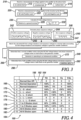
- the condition table 160 includes a set condition associations that are correlated to generator operating conditions.
- the condition table include a set of normal operation condition associations, a set of shorted condition associations indicative of operating conditions where a phase lead is shorted to the system or chassis ground and/or to another phase lead, and a set of rectifier internal fault condition associations.
- the condition table 160 includes a NORMAL GEN ON BALANCED condition association 162, a NORMAL GEN OFF condition association 164, and NORMAL IMBALANCED condition association 166.
- Each of associations 162-166 are discrete associations of combinations of calculated DC link voltage imbalance and sequence voltages expressed as a percentage of an expected value.
- this allows the fault detection method 200 (shown in FIG. 3 ) to provide indication of the operational status of the generator module 100 (shown in FIG. 1 ) in conjunction with a determination that the generator module 100 is operating in a normal condition.
- the condition table 160 also includes a plurality of generator internal fault condition associations.
- the condition table 160 includes a lead-to-ground short (L-G SHORT) condition association 168, a lead-to-lead short (L-L SHORT) condition association 170, a lead-to-lead-to-ground (L-L-G SHORT) condition association 172, a lead-to-lead-to-lead (L-L-L SHORT) condition association 174, and a lead-to-lead-to-lead-ground (L-L-L-G SHORT) condition association 176.
- Each of associations 168-176 are also discrete associations of combinations of calculated DC link voltage imbalance and sequence voltages.
- this allows the fault detection method 200 (shown in FIG. 3 ) to provide indication of both internal fault conditions in the generator 102 (shown in FIG. 1 ) as well as isolation of the fault condition to specific phase leads in the generator module 100 (shown in FIG. 1 ).
- the condition table 160 additionally includes a plurality of generator external fault condition associations.
- the condition table 160 includes a 1 TO 5 DIODES SHORT condition association 178, a 1 TO 5 DIODES OPEN condition association 180, an ALL 6 DIODES SHORT condition association 182, and an ALL 6 DIODES OPEN condition association 184.
- Each of associations 178-184 are additionally discrete associations of combinations of calculated DC link voltage imbalance and sequence voltages. As will be appreciated by those of skill in the art in view of the present disclosure, this allows the fault detection method 200 (shown in FIG. 3 ) to provide indication of both external fault conditions generator 102 (shown in FIG. 1 ), isolation of the fault condition to within the rectifier 118 (shown in FIG. 2 ), and identification of whether diodes within the rectifier 118 are short or open, and in certain embodiments, the specific number of open or short diodes within the rectifier 118.
- operations 270 and 280 of the fault detection method 200 are shown. Determining that a normal condition exists is made using the calculated DC link voltage imbalance and sequence voltages by matching the calculated DC link voltage imbalance and sequence voltages against associations 162-166 (shown in FIG. 4 ) of condition table 160 (shown in FIG. 4 ), as shown with box 274. If a match is found normal condition is also determined, as shown with box 276, and monitoring continues. If no match among the normal conditions is found for the calculated DC link voltage imbalance and voltage sequences, determination is made whether a fault condition exists.
- the system can be a countermeasure can be taken, such load shedding or de-energizing the system, according to the isolated fault condition.
- Determining whether a fault condition exists includes determining whether an internal fault exists, as shown with box 284. If an internal fault exists based on the matching of the calculated DC link voltage balance and sequence voltages, the fault is isolated to a specific lead or set of leads, as shown with box 286, and monitoring continues. If no match is identified among the internal fault associations 170-176, the determination is made whether an external fault exists in the generator module 100 (shown in FIG. 1 ), as shown with box 285. If an external fault exists based on the matching of the calculated DC link voltage balance and sequence voltages the fault is isolated to a set of open diodes or shorted diodes, as shown with box 287, and monitoring continues.
- the generator fault detection methods and generator modules of the present disclosure provide for fault detection without requiring measurement of current flow through phase leads connecting the power converter to the generator in VSCF generator modules
- the generator fault detection methods and generator modules of the present disclosure provide generator modules without current sensors located between the power converter and the generator in VSCF generator modules, thereby providing VSCF generator modules that are lightweight, compact, and/or exhibit relatively high reliability relative to generator modules employing current sensors. While the apparatus and methods of the subject disclosure have been shown and described with reference to preferred embodiments, those skilled in the art will readily appreciate that changes and/or modifications may be made thereto without departing from the scope of the invention as defined by the claims.
- embodiments can be in the form of processorimplemented processes and devices for practicing those processes, such as a processor.
- Embodiments can also be in the form of computer program code containing instructions embodied in tangible media, such as network cloud storage, SD cards, flash drives, floppy diskettes, CD ROMs, hard drives, or any other computer-readable storage medium, wherein, when the computer program code is loaded into and executed by a computer, the computer becomes a device for practicing the embodiments.
- Embodiments can also be in the form of computer program code, for example, whether stored in a storage medium, loaded into and/or executed by a computer, or transmitted over some transmission medium, loaded into and/or executed by a computer, or transmitted over some transmission medium, such as over electrical wiring or cabling, through fiber optics, or via electromagnetic radiation, wherein, when the computer program code is loaded into an executed by a computer, the computer becomes an device for practicing the embodiments.
- the computer program code segments configure the microprocessor to create specific logic circuits.
Landscapes
- Physics & Mathematics (AREA)
- General Physics & Mathematics (AREA)
- Engineering & Computer Science (AREA)
- Power Engineering (AREA)
- Optics & Photonics (AREA)
- Control Of Eletrric Generators (AREA)
Claims (15)
- Procédé de détection de défaillances, comprenant :au niveau d'un module de générateur (100), le fait d'avoir un générateur (102), un redresseur (118) connecté au générateur (102) par une pluralité de fils de phase (112, 114, 116), et un onduleur (122) connecté au redresseur (118) par une liaison courant continu, CC (120),la réception d'une mesure de tension appliquée au redresseur par les fils de phase sans utiliser de capteur de courant ;la réception d'une mesure de tension appliquée à l'onduleur par la liaison CC (120) ;le calcul de l'équilibre de tension de la liaison CC et des tensions de séquence de phases à l'aide de la mesure de la tension appliquée au redresseur (118) par les fils de phase (112, 114, 116) et de la mesure de la tension appliquée à l'onduleur (122) par la liaison CC (120) ;sur la base d'une correspondance, l'association du déséquilibre de tension de liaison CC et des tensions de séquence aux états du module de générateur ;sur la base de la correspondance, la détermination qu'un état normal existe à l'aide de l'équilibre de tension de liaison CC et des tensions de séquence de phases lorsqu'aucune défaillance n'existe dans le module de générateur (100) ; etsur la base de la correspondance, la détermination qu'un état de défaillance existe à l'aide de l'équilibre de tension de liaison CC et des tensions de séquence de phases lorsqu'une défaillance existe dans le module de générateur (100).
- Procédé selon la revendication 1, dans lequel la réception d'une mesure de tension appliquée au redresseur (118) comprend la mesure de la tension au niveau d'un fil de phase A (112), d'un fil de phase B (114) et d'un fil de phase C (116).
- Procédé selon la revendication 2, dans lequel le calcul des tensions de séquence de phases comprend le calcul de la tension de séquence positive, de la tension de séquence négative et de la tension de séquence zéro.
- Procédé selon la revendication 2, dans lequel le calcul des tensions de séquence de phases comprend le calcul de la tension de séquence positive selon : Vp = (Va + k*Vb + k2*Vc) , où k = -1/2 + j Sqrt (3)/2, et/ou dans lequel le calcul des tensions de séquence de phases comprend le calcul de la tension de séquence négative selon : Vn = (Va + k2*Vb + k*Vc) , où k = -1/2 + j Sqrt (3)/2, et/ou dans lequel le calcul des tensions de séquence de phases comprend le calcul de la tension de séquence zéro selon : Vz = Va + Vb + Vc.
- Procédé selon une quelconque revendication précédente, dans lequel la réception d'une mesure de tension appliquée à l'onduleur (122) par la liaison CC (120) comprend la mesure de la tension au niveau d'un fil positif (128) de liaison CC et d'un fil négatif (130) de liaison CC.
- Procédé selon la revendication 5, dans lequel les mesures de tension au niveau du fil positif (128) de liaison CC et du fil négatif (130) de liaison CC sont relatives à une borne de terre (142).
- Procédé selon la revendication 5 ou 6, dans lequel le déséquilibre de tension de liaison CC est calculé selon : Vdc = V+ - V-.
- Procédé selon une quelconque revendication précédente, dans lequel la détermination de l'existence d'un état normal comprend la détermination que le générateur (102) fonctionne dans un état déséquilibré.
- Procédé selon une quelconque revendication précédente, dans lequel la détermination de l'existence d'un état de défaillance comporte l'isolement de l'état de défaillance par rapport à une défaillance choisie parmi l'existence (a) d'un court-circuit L-G, (b) d'un court-circuit L-L, (c) d'un court-circuit L-L-G, (d) d'un court-circuit L-L-L, et (e) d'un court-circuit L-L-L-G dans le module de générateur.
- Procédé selon une quelconque revendication précédente, dans lequel la détermination de l'existence d'un état de défaillance comporte l'isolement de l'état de défaillance sur une diode en court-circuit à l'intérieur du redresseur, ou dans lequel la détermination de l'existence d'un état de défaillance comporte l'isolement de l'état de défaillance sur une diode ouverte à l'intérieur du redresseur (118).
- Procédé selon une quelconque revendication précédente, dans lequel la détermination qu'un état de défaillance existe comprend la mise en correspondance de l'équilibre de tension de liaison CC et des tensions de séquence calculés avec une table de correspondance associant le déséquilibre de tension de liaison CC et les tensions de séquence aux états du module de générateur.
- Module de générateur (100) ; comprenant :un générateur (102) ;un redresseur (118) connecté au générateur par une pluralité de fils de phase ;un onduleur (122) connecté au redresseur par une liaison à courant continu, CC, (120) ; etun dispositif de commande (126) disposé en communication avec la pluralité de fils de phase et la liaison CC, le dispositif de commande réagissant aux instructions enregistrées dans une mémoire pour exécuter le procédé selon une quelconque revendication précédente.
- Module de générateur selon la revendication 12, dans lequel la pluralité de fils de phase comprend un fil de phase A (112), un fil de phase B (114) et un fil de phase C (116), et comprenant en outre :un capteur de tension de phase A (132) couplé au fil de phase A et disposé en communication avec le dispositif de commande ;un capteur de tension de phase B (134) couplé au fil de phase B et disposé en communication avec le dispositif de commande ; etun capteur de tension de phase C (136) couplé au fil de phase C et disposé en communication avec le dispositif de commande.
- Module de générateur selon la revendication 12 ou 13, dans lequel la liaison CC comprend un fil positif (128) et un fil négatif (130), le module de générateur comprenant en outre :une borne de terre (142) ;un capteur de tension à fil positif (138) couplé au fil positif et à la borne de terre, le capteur de tension à fil positif étant disposé en communication avec le dispositif de commande ; etun capteur de tension à fil négatif (140) couplé au fil négatif et à la borne de terre, le capteur de tension à fil négatif étant disposé en communication avec le dispositif de commande.
- Module de générateur selon la revendication 12, 13 ou 14, dans lequel aucun capteur de courant n'est situé entre le générateur et le redresseur pour mesurer le courant à travers la pluralité de fils de phase reliant le générateur au redresseur, dans lequel la phase neutre du générateur n'est pas connectée à la terre.
Applications Claiming Priority (1)
| Application Number | Priority Date | Filing Date | Title |
|---|---|---|---|
| US16/212,192 US10746803B2 (en) | 2018-12-06 | 2018-12-06 | Fault detection and isolation in generator modules |
Publications (2)
| Publication Number | Publication Date |
|---|---|
| EP3663782A1 EP3663782A1 (fr) | 2020-06-10 |
| EP3663782B1 true EP3663782B1 (fr) | 2024-01-24 |
Family
ID=68808082
Family Applications (1)
| Application Number | Title | Priority Date | Filing Date |
|---|---|---|---|
| EP19213977.2A Active EP3663782B1 (fr) | 2018-12-06 | 2019-12-05 | Détection et isolation de défaillances dans des modules de générateurs |
Country Status (3)
| Country | Link |
|---|---|
| US (1) | US10746803B2 (fr) |
| EP (1) | EP3663782B1 (fr) |
| KR (1) | KR102738914B1 (fr) |
Families Citing this family (9)
| Publication number | Priority date | Publication date | Assignee | Title |
|---|---|---|---|---|
| US10756532B2 (en) * | 2018-07-13 | 2020-08-25 | Kohler Co. | Ground fault minimization |
| US11016135B2 (en) * | 2018-11-28 | 2021-05-25 | Cummins Power Generation Ip, Inc. | Systems and methods for ground fault detection in power systems using communication network |
| CN112345917B (zh) * | 2020-10-29 | 2022-04-01 | 株洲中车时代电气股份有限公司 | 一种变流器直流回路异常的监控方法及装置 |
| FR3117669A1 (fr) * | 2020-12-15 | 2022-06-17 | Valeo Equipements Electriques Moteur | Composant électronique de détection d’une défaillance d’au moins un interrupteur d’un redresseur pour véhicule |
| FR3117671B1 (fr) * | 2020-12-15 | 2024-03-01 | Valeo Equip Electr Moteur | Composant électronique de détection d’une défaillance d’au moins un interrupteur d’un redresseur pour véhicule |
| FR3117670A1 (fr) * | 2020-12-15 | 2022-06-17 | Valeo Equipements Electriques Moteur | Composant électronique de détection d’une défaillance d’au moins un interrupteur d’un redresseur pour véhicule |
| US11885850B2 (en) | 2021-11-08 | 2024-01-30 | Hamilton Sundstrand Corporation | Generator failure detection method |
| CN114325164B (zh) * | 2021-11-24 | 2023-03-10 | 合肥工业大学 | 单相三电平整流器多故障诊断方法 |
| US12332292B2 (en) | 2022-11-18 | 2025-06-17 | Cummins Power Generation Inc. | System for locating power faults based on a direction of current flow |
Family Cites Families (12)
| Publication number | Priority date | Publication date | Assignee | Title |
|---|---|---|---|---|
| US4956598A (en) | 1988-12-16 | 1990-09-11 | Sundstrand Corporation | Low distortion control for a VSCF generating system |
| US5552952A (en) | 1994-10-21 | 1996-09-03 | Sundstrand Corporation | Detection and isolation circuit for a failed bridge power rectifier and an electrical system employing same |
| RU2563964C2 (ru) | 2011-07-04 | 2015-09-27 | Абб Рисерч Лтд | Система, компьютерный программный продукт и способ обнаружения внутренних неисправностей обмотки синхронного генератора |
| US9595889B2 (en) * | 2013-02-15 | 2017-03-14 | Eaton Corporation | System and method for single-phase and three-phase current determination in power converters and inverters |
| EP2868913B1 (fr) | 2013-11-05 | 2017-10-04 | Openhydro IP Limited | Système et procédé de compensation de turbulence pour des générateurs de turbine |
| US9488698B2 (en) | 2014-11-20 | 2016-11-08 | Caterpillar Global Mining Equipment Llc | System and method for detecting diode failures |
| WO2016206688A1 (fr) | 2015-06-24 | 2016-12-29 | Vestas Wind Systems A/S | Courant d'appel commandé destiné à un filtre réseau connecté à un convertisseur |
| KR101722748B1 (ko) | 2015-10-13 | 2017-04-03 | 삼성중공업 주식회사 | 양방향 전력변환장치의 시험장치 |
| US10003186B2 (en) | 2016-06-15 | 2018-06-19 | Hamilton Sundstrand Corporation | Variable-speed constant-frequency power control |
| KR101791225B1 (ko) | 2016-12-29 | 2017-10-27 | 한국철도기술연구원 | 정류기 고장 진단 장치 및 방법 |
| US10848053B2 (en) * | 2018-07-13 | 2020-11-24 | Kohler Co. | Robust inverter topology |
| US10756532B2 (en) * | 2018-07-13 | 2020-08-25 | Kohler Co. | Ground fault minimization |
-
2018
- 2018-12-06 US US16/212,192 patent/US10746803B2/en active Active
-
2019
- 2019-12-03 KR KR1020190158761A patent/KR102738914B1/ko active Active
- 2019-12-05 EP EP19213977.2A patent/EP3663782B1/fr active Active
Also Published As
| Publication number | Publication date |
|---|---|
| US20200182934A1 (en) | 2020-06-11 |
| KR20200069237A (ko) | 2020-06-16 |
| EP3663782A1 (fr) | 2020-06-10 |
| KR102738914B1 (ko) | 2024-12-06 |
| US10746803B2 (en) | 2020-08-18 |
Similar Documents
| Publication | Publication Date | Title |
|---|---|---|
| EP3663782B1 (fr) | Détection et isolation de défaillances dans des modules de générateurs | |
| US9459320B2 (en) | Fault detection in brushless exciters | |
| US9910083B2 (en) | Rectifier diode fault detection in brushless exciters | |
| EP2482411B1 (fr) | Protection contre la défaillance d'entraînement | |
| US7042229B2 (en) | System and method for on line monitoring of insulation condition for DC machines | |
| EP3029473A2 (fr) | Système et procédé de détection de défaut à la terre dans un système de courant continu | |
| EP2730023A1 (fr) | Système, produit de programme informatique et procédé de détection des défauts d'enroulement internes d'un générateur synchrone | |
| EP2178185B1 (fr) | Détection de défaut de mise à la terre de commande de moteur | |
| EP3214757B1 (fr) | Procédé et appareil de détection de défaillance de composant de machine électrique | |
| EP3389177B1 (fr) | Moteurs électriques à détection de tension neutre | |
| JP4599120B2 (ja) | 電気設備の絶縁監視装置と方法 | |
| US10877097B2 (en) | DC monitoring system for variable frequency drives | |
| US10120347B2 (en) | Power generator protection unit | |
| CN107894549B (zh) | 差分故障检测系统 | |
| US6882173B1 (en) | Method and apparatus detecting shorted turns in an electric generator | |
| EP3648336A1 (fr) | Protection de courant différentiel d'enroulement parallèle de moteur | |
| WO2012113455A1 (fr) | Procédé pour obtenir une valeur de courant continu instantané et dispositif de commande | |
| CN120584293A (zh) | 用于检测工业感应电机的电气不平衡和早期绕组故障的系统和方法 |
Legal Events
| Date | Code | Title | Description |
|---|---|---|---|
| PUAI | Public reference made under article 153(3) epc to a published international application that has entered the european phase |
Free format text: ORIGINAL CODE: 0009012 |
|
| STAA | Information on the status of an ep patent application or granted ep patent |
Free format text: STATUS: THE APPLICATION HAS BEEN PUBLISHED |
|
| AK | Designated contracting states |
Kind code of ref document: A1 Designated state(s): AL AT BE BG CH CY CZ DE DK EE ES FI FR GB GR HR HU IE IS IT LI LT LU LV MC MK MT NL NO PL PT RO RS SE SI SK SM TR |
|
| AX | Request for extension of the european patent |
Extension state: BA ME |
|
| STAA | Information on the status of an ep patent application or granted ep patent |
Free format text: STATUS: REQUEST FOR EXAMINATION WAS MADE |
|
| 17P | Request for examination filed |
Effective date: 20201210 |
|
| RBV | Designated contracting states (corrected) |
Designated state(s): AL AT BE BG CH CY CZ DE DK EE ES FI FR GB GR HR HU IE IS IT LI LT LU LV MC MK MT NL NO PL PT RO RS SE SI SK SM TR |
|
| REG | Reference to a national code |
Ref country code: DE Ref legal event code: R079 Free format text: PREVIOUS MAIN CLASS: G01R0031400000 Ref document number: 602019045493 Country of ref document: DE Ipc: H02M0005458000 |
|
| GRAP | Despatch of communication of intention to grant a patent |
Free format text: ORIGINAL CODE: EPIDOSNIGR1 |
|
| STAA | Information on the status of an ep patent application or granted ep patent |
Free format text: STATUS: GRANT OF PATENT IS INTENDED |
|
| RIC1 | Information provided on ipc code assigned before grant |
Ipc: H02H 7/06 20060101ALN20230530BHEP Ipc: H02P 9/48 20060101ALN20230530BHEP Ipc: H02P 29/024 20160101ALI20230530BHEP Ipc: H02M 1/32 20070101ALI20230530BHEP Ipc: G01R 31/40 20200101ALI20230530BHEP Ipc: H02M 5/458 20060101AFI20230530BHEP |
|
| INTG | Intention to grant announced |
Effective date: 20230622 |
|
| RIC1 | Information provided on ipc code assigned before grant |
Ipc: H02H 7/06 20060101ALN20230609BHEP Ipc: H02P 9/48 20060101ALN20230609BHEP Ipc: H02P 29/024 20160101ALI20230609BHEP Ipc: H02M 1/32 20070101ALI20230609BHEP Ipc: G01R 31/40 20200101ALI20230609BHEP Ipc: H02M 5/458 20060101AFI20230609BHEP |
|
| GRAS | Grant fee paid |
Free format text: ORIGINAL CODE: EPIDOSNIGR3 |
|
| GRAA | (expected) grant |
Free format text: ORIGINAL CODE: 0009210 |
|
| STAA | Information on the status of an ep patent application or granted ep patent |
Free format text: STATUS: THE PATENT HAS BEEN GRANTED |
|
| AK | Designated contracting states |
Kind code of ref document: B1 Designated state(s): AL AT BE BG CH CY CZ DE DK EE ES FI FR GB GR HR HU IE IS IT LI LT LU LV MC MK MT NL NO PL PT RO RS SE SI SK SM TR |
|
| REG | Reference to a national code |
Ref country code: GB Ref legal event code: FG4D |
|
| REG | Reference to a national code |
Ref country code: CH Ref legal event code: EP |
|
| REG | Reference to a national code |
Ref country code: IE Ref legal event code: FG4D |
|
| REG | Reference to a national code |
Ref country code: DE Ref legal event code: R096 Ref document number: 602019045493 Country of ref document: DE |
|
| REG | Reference to a national code |
Ref country code: LT Ref legal event code: MG9D |
|
| REG | Reference to a national code |
Ref country code: NL Ref legal event code: MP Effective date: 20240124 |
|
| PG25 | Lapsed in a contracting state [announced via postgrant information from national office to epo] |
Ref country code: NL Free format text: LAPSE BECAUSE OF FAILURE TO SUBMIT A TRANSLATION OF THE DESCRIPTION OR TO PAY THE FEE WITHIN THE PRESCRIBED TIME-LIMIT Effective date: 20240124 |
|
| PG25 | Lapsed in a contracting state [announced via postgrant information from national office to epo] |
Ref country code: NL Free format text: LAPSE BECAUSE OF FAILURE TO SUBMIT A TRANSLATION OF THE DESCRIPTION OR TO PAY THE FEE WITHIN THE PRESCRIBED TIME-LIMIT Effective date: 20240124 |
|
| PG25 | Lapsed in a contracting state [announced via postgrant information from national office to epo] |
Ref country code: IS Free format text: LAPSE BECAUSE OF FAILURE TO SUBMIT A TRANSLATION OF THE DESCRIPTION OR TO PAY THE FEE WITHIN THE PRESCRIBED TIME-LIMIT Effective date: 20240524 |
|
| PG25 | Lapsed in a contracting state [announced via postgrant information from national office to epo] |
Ref country code: LT Free format text: LAPSE BECAUSE OF FAILURE TO SUBMIT A TRANSLATION OF THE DESCRIPTION OR TO PAY THE FEE WITHIN THE PRESCRIBED TIME-LIMIT Effective date: 20240124 |
|
| PG25 | Lapsed in a contracting state [announced via postgrant information from national office to epo] |
Ref country code: GR Free format text: LAPSE BECAUSE OF FAILURE TO SUBMIT A TRANSLATION OF THE DESCRIPTION OR TO PAY THE FEE WITHIN THE PRESCRIBED TIME-LIMIT Effective date: 20240425 |
|
| REG | Reference to a national code |
Ref country code: AT Ref legal event code: MK05 Ref document number: 1652953 Country of ref document: AT Kind code of ref document: T Effective date: 20240124 |
|
| PG25 | Lapsed in a contracting state [announced via postgrant information from national office to epo] |
Ref country code: HR Free format text: LAPSE BECAUSE OF FAILURE TO SUBMIT A TRANSLATION OF THE DESCRIPTION OR TO PAY THE FEE WITHIN THE PRESCRIBED TIME-LIMIT Effective date: 20240124 Ref country code: RS Free format text: LAPSE BECAUSE OF FAILURE TO SUBMIT A TRANSLATION OF THE DESCRIPTION OR TO PAY THE FEE WITHIN THE PRESCRIBED TIME-LIMIT Effective date: 20240424 |
|
| PG25 | Lapsed in a contracting state [announced via postgrant information from national office to epo] |
Ref country code: ES Free format text: LAPSE BECAUSE OF FAILURE TO SUBMIT A TRANSLATION OF THE DESCRIPTION OR TO PAY THE FEE WITHIN THE PRESCRIBED TIME-LIMIT Effective date: 20240124 |
|
| PG25 | Lapsed in a contracting state [announced via postgrant information from national office to epo] |
Ref country code: AT Free format text: LAPSE BECAUSE OF FAILURE TO SUBMIT A TRANSLATION OF THE DESCRIPTION OR TO PAY THE FEE WITHIN THE PRESCRIBED TIME-LIMIT Effective date: 20240124 |
|
| PG25 | Lapsed in a contracting state [announced via postgrant information from national office to epo] |
Ref country code: RS Free format text: LAPSE BECAUSE OF FAILURE TO SUBMIT A TRANSLATION OF THE DESCRIPTION OR TO PAY THE FEE WITHIN THE PRESCRIBED TIME-LIMIT Effective date: 20240424 Ref country code: NO Free format text: LAPSE BECAUSE OF FAILURE TO SUBMIT A TRANSLATION OF THE DESCRIPTION OR TO PAY THE FEE WITHIN THE PRESCRIBED TIME-LIMIT Effective date: 20240424 Ref country code: LT Free format text: LAPSE BECAUSE OF FAILURE TO SUBMIT A TRANSLATION OF THE DESCRIPTION OR TO PAY THE FEE WITHIN THE PRESCRIBED TIME-LIMIT Effective date: 20240124 Ref country code: IS Free format text: LAPSE BECAUSE OF FAILURE TO SUBMIT A TRANSLATION OF THE DESCRIPTION OR TO PAY THE FEE WITHIN THE PRESCRIBED TIME-LIMIT Effective date: 20240524 Ref country code: HR Free format text: LAPSE BECAUSE OF FAILURE TO SUBMIT A TRANSLATION OF THE DESCRIPTION OR TO PAY THE FEE WITHIN THE PRESCRIBED TIME-LIMIT Effective date: 20240124 Ref country code: GR Free format text: LAPSE BECAUSE OF FAILURE TO SUBMIT A TRANSLATION OF THE DESCRIPTION OR TO PAY THE FEE WITHIN THE PRESCRIBED TIME-LIMIT Effective date: 20240425 Ref country code: FI Free format text: LAPSE BECAUSE OF FAILURE TO SUBMIT A TRANSLATION OF THE DESCRIPTION OR TO PAY THE FEE WITHIN THE PRESCRIBED TIME-LIMIT Effective date: 20240124 Ref country code: ES Free format text: LAPSE BECAUSE OF FAILURE TO SUBMIT A TRANSLATION OF THE DESCRIPTION OR TO PAY THE FEE WITHIN THE PRESCRIBED TIME-LIMIT Effective date: 20240124 Ref country code: BG Free format text: LAPSE BECAUSE OF FAILURE TO SUBMIT A TRANSLATION OF THE DESCRIPTION OR TO PAY THE FEE WITHIN THE PRESCRIBED TIME-LIMIT Effective date: 20240124 Ref country code: AT Free format text: LAPSE BECAUSE OF FAILURE TO SUBMIT A TRANSLATION OF THE DESCRIPTION OR TO PAY THE FEE WITHIN THE PRESCRIBED TIME-LIMIT Effective date: 20240124 |
|
| PG25 | Lapsed in a contracting state [announced via postgrant information from national office to epo] |
Ref country code: PL Free format text: LAPSE BECAUSE OF FAILURE TO SUBMIT A TRANSLATION OF THE DESCRIPTION OR TO PAY THE FEE WITHIN THE PRESCRIBED TIME-LIMIT Effective date: 20240124 Ref country code: PT Free format text: LAPSE BECAUSE OF FAILURE TO SUBMIT A TRANSLATION OF THE DESCRIPTION OR TO PAY THE FEE WITHIN THE PRESCRIBED TIME-LIMIT Effective date: 20240524 |
|
| PG25 | Lapsed in a contracting state [announced via postgrant information from national office to epo] |
Ref country code: SE Free format text: LAPSE BECAUSE OF FAILURE TO SUBMIT A TRANSLATION OF THE DESCRIPTION OR TO PAY THE FEE WITHIN THE PRESCRIBED TIME-LIMIT Effective date: 20240124 Ref country code: PT Free format text: LAPSE BECAUSE OF FAILURE TO SUBMIT A TRANSLATION OF THE DESCRIPTION OR TO PAY THE FEE WITHIN THE PRESCRIBED TIME-LIMIT Effective date: 20240524 Ref country code: PL Free format text: LAPSE BECAUSE OF FAILURE TO SUBMIT A TRANSLATION OF THE DESCRIPTION OR TO PAY THE FEE WITHIN THE PRESCRIBED TIME-LIMIT Effective date: 20240124 Ref country code: LV Free format text: LAPSE BECAUSE OF FAILURE TO SUBMIT A TRANSLATION OF THE DESCRIPTION OR TO PAY THE FEE WITHIN THE PRESCRIBED TIME-LIMIT Effective date: 20240124 |
|
| PG25 | Lapsed in a contracting state [announced via postgrant information from national office to epo] |
Ref country code: DK Free format text: LAPSE BECAUSE OF FAILURE TO SUBMIT A TRANSLATION OF THE DESCRIPTION OR TO PAY THE FEE WITHIN THE PRESCRIBED TIME-LIMIT Effective date: 20240124 |
|
| PG25 | Lapsed in a contracting state [announced via postgrant information from national office to epo] |
Ref country code: SM Free format text: LAPSE BECAUSE OF FAILURE TO SUBMIT A TRANSLATION OF THE DESCRIPTION OR TO PAY THE FEE WITHIN THE PRESCRIBED TIME-LIMIT Effective date: 20240124 |
|
| PG25 | Lapsed in a contracting state [announced via postgrant information from national office to epo] |
Ref country code: CZ Free format text: LAPSE BECAUSE OF FAILURE TO SUBMIT A TRANSLATION OF THE DESCRIPTION OR TO PAY THE FEE WITHIN THE PRESCRIBED TIME-LIMIT Effective date: 20240124 Ref country code: EE Free format text: LAPSE BECAUSE OF FAILURE TO SUBMIT A TRANSLATION OF THE DESCRIPTION OR TO PAY THE FEE WITHIN THE PRESCRIBED TIME-LIMIT Effective date: 20240124 |
|
| REG | Reference to a national code |
Ref country code: DE Ref legal event code: R097 Ref document number: 602019045493 Country of ref document: DE |
|
| PG25 | Lapsed in a contracting state [announced via postgrant information from national office to epo] |
Ref country code: SK Free format text: LAPSE BECAUSE OF FAILURE TO SUBMIT A TRANSLATION OF THE DESCRIPTION OR TO PAY THE FEE WITHIN THE PRESCRIBED TIME-LIMIT Effective date: 20240124 |
|
| PG25 | Lapsed in a contracting state [announced via postgrant information from national office to epo] |
Ref country code: SM Free format text: LAPSE BECAUSE OF FAILURE TO SUBMIT A TRANSLATION OF THE DESCRIPTION OR TO PAY THE FEE WITHIN THE PRESCRIBED TIME-LIMIT Effective date: 20240124 Ref country code: SK Free format text: LAPSE BECAUSE OF FAILURE TO SUBMIT A TRANSLATION OF THE DESCRIPTION OR TO PAY THE FEE WITHIN THE PRESCRIBED TIME-LIMIT Effective date: 20240124 Ref country code: RO Free format text: LAPSE BECAUSE OF FAILURE TO SUBMIT A TRANSLATION OF THE DESCRIPTION OR TO PAY THE FEE WITHIN THE PRESCRIBED TIME-LIMIT Effective date: 20240124 Ref country code: EE Free format text: LAPSE BECAUSE OF FAILURE TO SUBMIT A TRANSLATION OF THE DESCRIPTION OR TO PAY THE FEE WITHIN THE PRESCRIBED TIME-LIMIT Effective date: 20240124 Ref country code: DK Free format text: LAPSE BECAUSE OF FAILURE TO SUBMIT A TRANSLATION OF THE DESCRIPTION OR TO PAY THE FEE WITHIN THE PRESCRIBED TIME-LIMIT Effective date: 20240124 Ref country code: CZ Free format text: LAPSE BECAUSE OF FAILURE TO SUBMIT A TRANSLATION OF THE DESCRIPTION OR TO PAY THE FEE WITHIN THE PRESCRIBED TIME-LIMIT Effective date: 20240124 |
|
| PLBE | No opposition filed within time limit |
Free format text: ORIGINAL CODE: 0009261 |
|
| STAA | Information on the status of an ep patent application or granted ep patent |
Free format text: STATUS: NO OPPOSITION FILED WITHIN TIME LIMIT |
|
| PG25 | Lapsed in a contracting state [announced via postgrant information from national office to epo] |
Ref country code: IT Free format text: LAPSE BECAUSE OF FAILURE TO SUBMIT A TRANSLATION OF THE DESCRIPTION OR TO PAY THE FEE WITHIN THE PRESCRIBED TIME-LIMIT Effective date: 20240124 |
|
| PG25 | Lapsed in a contracting state [announced via postgrant information from national office to epo] |
Ref country code: IT Free format text: LAPSE BECAUSE OF FAILURE TO SUBMIT A TRANSLATION OF THE DESCRIPTION OR TO PAY THE FEE WITHIN THE PRESCRIBED TIME-LIMIT Effective date: 20240124 |
|
| 26N | No opposition filed |
Effective date: 20241025 |
|
| PG25 | Lapsed in a contracting state [announced via postgrant information from national office to epo] |
Ref country code: SI Free format text: LAPSE BECAUSE OF FAILURE TO SUBMIT A TRANSLATION OF THE DESCRIPTION OR TO PAY THE FEE WITHIN THE PRESCRIBED TIME-LIMIT Effective date: 20240124 |
|
| PG25 | Lapsed in a contracting state [announced via postgrant information from national office to epo] |
Ref country code: MC Free format text: LAPSE BECAUSE OF FAILURE TO SUBMIT A TRANSLATION OF THE DESCRIPTION OR TO PAY THE FEE WITHIN THE PRESCRIBED TIME-LIMIT Effective date: 20240124 |
|
| REG | Reference to a national code |
Ref country code: CH Ref legal event code: PL |
|
| PG25 | Lapsed in a contracting state [announced via postgrant information from national office to epo] |
Ref country code: LU Free format text: LAPSE BECAUSE OF NON-PAYMENT OF DUE FEES Effective date: 20241205 |
|
| REG | Reference to a national code |
Ref country code: BE Ref legal event code: MM Effective date: 20241231 |
|
| PG25 | Lapsed in a contracting state [announced via postgrant information from national office to epo] |
Ref country code: BE Free format text: LAPSE BECAUSE OF NON-PAYMENT OF DUE FEES Effective date: 20241231 |
|
| PG25 | Lapsed in a contracting state [announced via postgrant information from national office to epo] |
Ref country code: CH Free format text: LAPSE BECAUSE OF NON-PAYMENT OF DUE FEES Effective date: 20241231 |
|
| PG25 | Lapsed in a contracting state [announced via postgrant information from national office to epo] |
Ref country code: IE Free format text: LAPSE BECAUSE OF NON-PAYMENT OF DUE FEES Effective date: 20241205 |
|
| PGFP | Annual fee paid to national office [announced via postgrant information from national office to epo] |
Ref country code: DE Payment date: 20251126 Year of fee payment: 7 |
|
| PGFP | Annual fee paid to national office [announced via postgrant information from national office to epo] |
Ref country code: GB Payment date: 20251120 Year of fee payment: 7 |
|
| PGFP | Annual fee paid to national office [announced via postgrant information from national office to epo] |
Ref country code: FR Payment date: 20251120 Year of fee payment: 7 |
|
| PG25 | Lapsed in a contracting state [announced via postgrant information from national office to epo] |
Ref country code: CY Free format text: LAPSE BECAUSE OF FAILURE TO SUBMIT A TRANSLATION OF THE DESCRIPTION OR TO PAY THE FEE WITHIN THE PRESCRIBED TIME-LIMIT; INVALID AB INITIO Effective date: 20191205 |