EP3663797A1 - Dispositif de surveillance - Google Patents
Dispositif de surveillance Download PDFInfo
- Publication number
- EP3663797A1 EP3663797A1 EP18210965.2A EP18210965A EP3663797A1 EP 3663797 A1 EP3663797 A1 EP 3663797A1 EP 18210965 A EP18210965 A EP 18210965A EP 3663797 A1 EP3663797 A1 EP 3663797A1
- Authority
- EP
- European Patent Office
- Prior art keywords
- optical sensor
- monitoring device
- periodic control
- protective
- control unit
- Prior art date
- Legal status (The legal status is an assumption and is not a legal conclusion. Google has not performed a legal analysis and makes no representation as to the accuracy of the status listed.)
- Withdrawn
Links
Images

Classifications
-
- G—PHYSICS
- G05—CONTROLLING; REGULATING
- G05B—CONTROL OR REGULATING SYSTEMS IN GENERAL; FUNCTIONAL ELEMENTS OF SUCH SYSTEMS; MONITORING OR TESTING ARRANGEMENTS FOR SUCH SYSTEMS OR ELEMENTS
- G05B19/00—Program-control systems
- G05B19/02—Program-control systems electric
- G05B19/18—Numerical control [NC], i.e. automatically operating machines, in particular machine tools, e.g. in a manufacturing environment, so as to execute positioning, movement or co-ordinated operations by means of program data in numerical form
- G05B19/406—Numerical control [NC], i.e. automatically operating machines, in particular machine tools, e.g. in a manufacturing environment, so as to execute positioning, movement or co-ordinated operations by means of program data in numerical form characterised by monitoring or safety
-
- G—PHYSICS
- G01—MEASURING; TESTING
- G01S—RADIO DIRECTION-FINDING; RADIO NAVIGATION; DETERMINING DISTANCE OR VELOCITY BY USE OF RADIO WAVES; LOCATING OR PRESENCE-DETECTING BY USE OF THE REFLECTION OR RERADIATION OF RADIO WAVES; ANALOGOUS ARRANGEMENTS USING OTHER WAVES
- G01S17/00—Systems using the reflection or reradiation of electromagnetic waves other than radio waves, e.g. lidar systems
- G01S17/02—Systems using the reflection of electromagnetic waves other than radio waves
- G01S17/06—Systems determining position data of a target
- G01S17/42—Simultaneous measurement of distance and other co-ordinates
-
- G—PHYSICS
- G01—MEASURING; TESTING
- G01S—RADIO DIRECTION-FINDING; RADIO NAVIGATION; DETERMINING DISTANCE OR VELOCITY BY USE OF RADIO WAVES; LOCATING OR PRESENCE-DETECTING BY USE OF THE REFLECTION OR RERADIATION OF RADIO WAVES; ANALOGOUS ARRANGEMENTS USING OTHER WAVES
- G01S17/00—Systems using the reflection or reradiation of electromagnetic waves other than radio waves, e.g. lidar systems
- G01S17/88—Lidar systems specially adapted for specific applications
- G01S17/93—Lidar systems specially adapted for specific applications for anti-collision purposes
- G01S17/931—Lidar systems specially adapted for specific applications for anti-collision purposes of land vehicles
-
- G—PHYSICS
- G05—CONTROLLING; REGULATING
- G05B—CONTROL OR REGULATING SYSTEMS IN GENERAL; FUNCTIONAL ELEMENTS OF SUCH SYSTEMS; MONITORING OR TESTING ARRANGEMENTS FOR SUCH SYSTEMS OR ELEMENTS
- G05B2219/00—Program-control systems
- G05B2219/30—Nc systems
- G05B2219/37—Measurements
- G05B2219/37572—Camera, tv, vision
-
- G—PHYSICS
- G05—CONTROLLING; REGULATING
- G05B—CONTROL OR REGULATING SYSTEMS IN GENERAL; FUNCTIONAL ELEMENTS OF SUCH SYSTEMS; MONITORING OR TESTING ARRANGEMENTS FOR SUCH SYSTEMS OR ELEMENTS
- G05B2219/00—Program-control systems
- G05B2219/30—Nc systems
- G05B2219/49—Nc machine tool, till multiple
- G05B2219/49137—Store working envelop, limit, allowed zone
Definitions
- the invention relates to a monitoring device and a method for operating a monitoring device.
- Monitoring devices of this type are used in particular in the field of safety technology and are generally used to protect dangerous systems which can generally be formed by stationary machines or work equipment or else by vehicles.
- the monitoring device generally comprises a control unit and an optical sensor, the control unit being designed as a safety controller and the optical sensor as a safety sensor for use in the field of safety technology.
- the control unit is used to control the system, for which purpose the optical sensor is also controlled by the control unit.
- a danger zone on the system is monitored with the optical sensor.
- the optical sensor is typically designed as an area distance sensor.
- a surface distance sensor typically has a distance sensor with a light beam emitting transmitter and a light beam receiving receiver. The light rays of the transmitter are periodically deflected in an angular range and thus periodically scan a monitoring area in individual scans.
- protective field monitoring is carried out in such a way that a protective field is specified in the optical sensor, the dimensions of which are adapted to the hazardous area to be monitored.
- a monitoring function is then implemented with the optical sensor such that in Depending on the sensor signals of the distance sensor, a binary object detection signal is generated, the switching states of which indicate whether an object is present in the protective field or not. If an object is detected in the protective field, the corresponding object detection signal is transmitted to the controller, which triggers a safety function that avoids dangerous situations for people. In the case of a stationary system, for example, this system can be stopped by the generated object detection signal. In the event that the system is a vehicle, the vehicle can be stopped by the object detection signal.
- the danger zone to be protected can change over time. In such cases, it is not sufficient to store a single protective field in the optical sensor.
- From the DE 199 17 509 C1 describes an optical sensor in whose evaluation unit several protective fields are stored. A specific input can be assigned to each protective field. A suitable protective field can be selected via these inputs.
- the disadvantage here is that only a limited number of protective fields can be specified in the optical sensor.
- Another disadvantage is that a complex input structure is required for the selection of the protective fields, which entails high construction and cost expenditure. After all, the selection of protective fields and their verification is relatively time-consuming. This means that applications requiring a highly dynamic adaptation of the protective field can only be insufficiently implemented.
- the invention has for its object to provide a monitoring device with high functionality.
- the invention relates to a monitoring device with a control unit and an optical sensor.
- the control unit is designed to control the optical sensor.
- At least one periodic control signal is transmitted from the control unit to the optical sensor.
- Different configurations of a parameter of the periodic control signal in the form of the frequency, the pulse widths, the pulse pauses or the pulse width / pulse pause ratio define different protective fields for the optical sensor.
- the invention further relates to a corresponding method.
- control unit for the optical sensor continuously, that is to say continuously, specifies the protective field within which the optical sensor carries out object monitoring by means of the periodic control signal.
- the control unit can specify the protective field of the optical sensor by changing a parameter of the periodic control signal.
- the protective field can thus be changed quickly in the optical sensor, which enables flexible and rapid adaptation to different application conditions, in particular dangerous situations.
- the specification of a protective field generally also includes the case that several partial protective fields can be specified at the same time.
- An essential advantage of the invention is that the dimensions of protective fields for the optical sensor can be specified directly by the different configurations of parameters in the control unit.
- a characteristic field is preferably stored in the optical sensor, on the basis of which a specific protective field is assigned to each characteristic.
- Another advantage of the invention is that based on the parameter in the form of Frequency, the pulse widths, the pulse pauses or the pulse width / pulse pause ratios, a very large number of different protective fields can be specified, since these variables can be changed virtually continuously in order to specify different protective fields.
- the parameters of the periodic control signal can be varied very quickly in the control unit, so that the current protective field of the optical transmitter can accordingly be changed quickly.
- a monitoring function is generally implemented with the optical sensor in such a way that objects penetrating into the respectively activated protective field are detected.
- a binary object detection signal is generated in the optical sensor, the switching states of which indicate whether an object is in the protective field or not.
- This object detection signal is output to the control unit, where the object detection signal can be used for control functions.
- control unit is a safety controller.
- the optical sensor is a safety sensor.
- the monitoring device can thus be used in the field of security technology, in particular in the field of personal protection.
- the monitoring device monitors a danger area of a system.
- the protective field can be adapted accordingly. If an object is detected in the protective field with the optical sensor, the object detection signal generated thereby is used to trigger a safety function in the control unit, which generally brings the monitored system into a safe state.
- the monitored system can be designed to be stationary, for example in the form of a machine or an implement.
- the safety function can consist of shutting down the entire system or its dangerous part.
- the monitoring device is used particularly advantageously in a vehicle, such as a driverless transport vehicle.
- the control unit is then used for vehicle control, the optical sensor is preferably used for monitoring the apron of the vehicle.
- the variation of the protective fields according to the invention can then advantageously be used for a speed-dependent adaptation of the protective field. Since the protective field variation can take place quasi-continuously, that is to say in very small steps and also very quickly, depending on the parameter of the periodic control signal, an exact adaptation of the protective fields to the vehicle speed is possible, even if this changes rapidly.
- the parameter varies between an upper and lower base value.
- a minimum and maximum dimension of a protective field is specified by the base values.
- the minimum protective field size can correspond to size zero, so that in this case protective field monitoring is no longer carried out.
- protective fields are specified by means of two independent periodic control signals. This considerably increases the reliability of the protective field specification, since the two periodic control signals provide a redundant signal for the protective field specification.
- the parameters of the two periodic control signals for specifying a protective field are particularly advantageous.
- the periodic control signals are transmitted to the optical transmitter via separate lines.
- the parameters serving to specify a protective field are advantageously transmitted to the optical sensor at the same time.
- the two periodic control signals for specifying a protective field are present at the same time, they can be compared immediately, so that the validity check and the subsequent protective field activation can be carried out very quickly.
- the periodic control signals are transmitted to the optical sensor via a common line.
- the periodic control signals can be superimposed.
- the periodic control signals can then be transmitted again in parallel with the specification of a protective field.
- the validity check of the periodic control signals can accordingly take place without a time delay, the validity check being carried out in particular by comparing the control signals.
- the periodic control signals can be transmitted at different times.
- the time offset of the periodic control signals in the optical sensor must be known.
- the optical sensor is an area distance sensor which has a distance sensor with a transmitter and receiver.
- the light rays from the transmitter are periodically guided in the protective field.
- the light beams of the transmitter are deflected with a deflection unit or the distance sensor is integrated in a rotating measuring head.
- the optical sensor can also be designed as a distance-measuring camera.
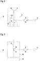
- Figure 1 has an example of the monitoring device 1 according to the invention.
- the monitoring device 1 serves to monitor the apron of a vehicle 2.
- the monitoring device 1 has a control unit 3 and an optical sensor 4.
- the control unit 3 is designed as a safety controller for use in the field of safety technology.
- the optical sensor 4 is designed as a safety sensor. This is realized by a fail-safe structure of the control unit 3 and the optical sensor 4.
- the control unit 3 is used to control the vehicle 2.
- the apron of the vehicle 2 is monitored with the optical sensor 4.
- the optical sensor 4 detects objects in a protective field 5a, 5b, 5c.
- about the control units 3 can for the optical Sensor 4 different protective fields 5a, 5b, 5c are predetermined, the predetermined protective fields 5a, 5b, 5c depending on the speed of the vehicle 2.
- FIG 1 three different protective fields 5a, 5b, 5c are shown.
- the control unit 3 specifies a considerably larger number of protective fields 5a, 5b, 5c.
- all protective fields 5a, 5b, 5c have the same width, since the vehicle 2 is moved along a time-limited roadway.
- the protective fields 5a, 5b, 5c thus also differ in their length, that is to say by their protective field boundary facing away from the vehicle 2.
- the control unit 3 is connected to the optical sensor 4 via two lines 6a, 6b. Furthermore, the optical sensor 4 has a fail-safe output (not shown in the figures), via which a binary object detection signal generated in the optical sensor 4 is read into the control unit 3.
- the switching states of the object detection signal indicate whether an object is in the current protective field 5a, 5b, 5c or not. If the optical sensor 4 detects an object in the protective field 5a, 5b, 5c and a corresponding object detection signal is generated, the control unit 3 triggers a safety function depending on the object detection signal.
- the safety function advantageously consists of a stop or brake command for the vehicle 2.
- the optical sensor 4 is designed as an area distance sensor.
- Figure 2 shows a first embodiment of an area distance sensor.
- the surface distance sensor has a distance sensor arranged in a stationary manner in a housing 7 with a transmitter 9 emitting light rays 8 and a receiver 10 received light rays 8.
- the transmitter 9 is, for example, from a laser diode, the receiver 10 by a photodiode.
- the distances of objects are determined, for example, using a pulse transit time method, for which purpose the transmitter 9 emits light rays 8 in the form of light pulses.
- the light rays 8 emitted by the transmitter 9, as well as the light rays 8 reflected back by an object to be detected, that is to say an object 11 with a remitting surface, are guided over a mirror surface 12a of a deflection unit 12.
- the light rays 8 are deflected in an angular range.
- positions of objects, in particular within a protective field 5a, 5b, 5c can be detected.
- Figure 3 shows a variant of the area distance sensor according to Figure 2 .
- the area distance sensor according to Figure 3 differs from the area distance sensor according to Figure 2 in that the transmitter 9 and receiver 10 of the distance sensor are mounted in a measuring head 14 which is mounted on a base 13 and rotatable about an axis of rotation D.
- a protective field 5a, 5b, 5c with a sequence of scans is periodically scanned with the light beams 8 by their deflecting movement.
- the current distance values and deflection positions of the light beams 8 are evaluated in an evaluation unit in order to generate the object detection signal.
- the evaluation unit has a redundant structure, preferably in the form of two computer units that monitor one another cyclically.
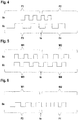
- FIGS. 4 - 6 show different variants of the specification of protective fields 5a, 5b, 5c of the optical sensor 4 by the control unit 3 according to the invention.
- a periodic control signal is entered into the optical sensor 4 via the lines 6a, 6b, by means of which a constant, that is to say permanent, specification of a protective field 5a, 5b, 5c for the optical sensor 4 takes place.
- the specification of a protective field 5a, 5b, 5c can generally also be configured such that a protective field 5a, 5b, 5c comprises several partial protective fields, which at least partially cover different spatial areas.
- a protective field 5a, 5b, 5c can also be specified only via one line.
- two periodic control signals can be transmitted via a line, either in such a way that they are superimposed, in which case the periodic control signals are separated in the evaluation unit of the optical sensor 4.
- the periodic control signals can be transmitted at different times over the line.
- the periodic control signals designed as discrete pulse sequences vary with regard to a characteristic variable, which are formed either by the frequency of the pulse widths, the pulse pauses or the pulse width / pulse pause ratio.
- Different protective fields 5a, 5b, 5c in the optical sensor 4 are evaluated by specifying different parameters.
- the different parameters thus encode different protective fields 5a, 5b, 5c, and these encodings can be clearly detected and recognized in the evaluation unit.
- corresponding characteristic curve fields with a clear assignment of values of the characteristic variables to the protective fields 5a, 5b, 5c can be stored in the evaluation unit of the optical sensor 4.
- Figure 4 shows a first embodiment of a specification of protective fields 5a, 5b, 5c by reading two periodic control signals via lines 6a, 6b into the optical sensor 4.
- the periodic control signals read in via lines 6a, 6b differ in their frequencies, like the time diagrams shown demonstrate.
- a periodic control signal with frequency F1 is first read in via line 6a and a periodic control signal with frequency F3 is read in via line 6b.
- a first protective field 5a is only activated in the optical sensor 4 if the periodic control signal with the frequency F1 and the periodic control signal with the frequency F3 are simultaneously detected on the line 6a in the evaluation unit.
- the protective field 5a is specified continuously, that is to say the protective field 5a remains activated as long as these periodic control signals are recognized.
- control unit 3 switches the periodic control signal on line 6a from frequencies F1 to frequency F2. Furthermore, the control unit 3 switches the periodic control signal on the line 6b from the frequency F3 to the frequency F4 at the same time to.
- a protective field 5b is activated in the evaluation unit only if the periodic control signal with the frequency F2 and the periodic control signal with the frequency F4 are registered on the line 6a in the evaluation unit of the optical sensor 4.
- the frequencies of the periodic control signals can be varied almost continuously, depending on the speed of the vehicle 2, a correspondingly high number of different protective fields 5a, 5b, 5c can be specified for the optical sensor 4, so that the protective field size is quasi-continuous with the speed of the vehicle 2 can be adjusted.
- the frequency variation of the periodic control signals advantageously takes place between a lower and an upper base value, the lower base value defining a minimum protective field size, which can in particular be zero, and the upper base value defining a maximum protective field size.
- the lower and upper base values for the two periodic control signals are advantageously different.
- Figure 5 shows a further embodiment of the specification of protective fields 5a, 5b, 5c for the optical sensor 4 by periodic control signals on the lines 6a, 6b.
- the embodiment of the Figure 5 differs from the embodiment of Figure 4 only in that the periodic control signals do not differ in terms of their frequencies F1 - F4 but in terms of their pulse widths W1 - W4. Accordingly, at times t ⁇ to, a protective field 5a is activated by registering a periodic control signal with pulse width W1 on line 6a and a periodic control signal with pulse width W3 on line 6b in optical sensor 4.
- a protective field 5b is activated by registering a periodic control signal with pulse width W2 on line 6a and a periodic control signal with pulse width W4 on line 6b.
- a periodic control signal with pulse width W2 on line 6a and a periodic control signal with pulse width W4 on line 6b.
- lower and upper base values were defined for the pulse widths of the periodic control signals.
- the embodiment according to Figure 5 can be varied such that the periodic control signals do not differ with regard to the pulse width, but with regard to the pulse pause or the pulse width / pulse pause ratio.
- Protective fields 5a, 5b, 5c are only specified for the optical sensor 4 via a periodic control signal which changes with regard to its frequency F3, F4 and with regard to its pulse width W1, W2.
- a protective field 5a is activated by registering a periodic control signal with the frequency F2 and the pulse width W1 on the line 6a.
- a further protective field 5b is activated by registering a periodic control signal with frequency F4 and pulse width W2 on line 6b.
- An error control is carried out in the optical sensor 4 by checking the frequency and the pulse width of the periodic control signal. These variables must have a certain relationship to each other, otherwise there is an error condition.
Landscapes
- Physics & Mathematics (AREA)
- Engineering & Computer Science (AREA)
- Electromagnetism (AREA)
- General Physics & Mathematics (AREA)
- Computer Networks & Wireless Communication (AREA)
- Radar, Positioning & Navigation (AREA)
- Remote Sensing (AREA)
- Human Computer Interaction (AREA)
- Manufacturing & Machinery (AREA)
- Automation & Control Theory (AREA)
- Optical Radar Systems And Details Thereof (AREA)
Priority Applications (1)
| Application Number | Priority Date | Filing Date | Title |
|---|---|---|---|
| EP18210965.2A EP3663797A1 (fr) | 2018-12-07 | 2018-12-07 | Dispositif de surveillance |
Applications Claiming Priority (1)
| Application Number | Priority Date | Filing Date | Title |
|---|---|---|---|
| EP18210965.2A EP3663797A1 (fr) | 2018-12-07 | 2018-12-07 | Dispositif de surveillance |
Publications (1)
| Publication Number | Publication Date |
|---|---|
| EP3663797A1 true EP3663797A1 (fr) | 2020-06-10 |
Family
ID=64664585
Family Applications (1)
| Application Number | Title | Priority Date | Filing Date |
|---|---|---|---|
| EP18210965.2A Withdrawn EP3663797A1 (fr) | 2018-12-07 | 2018-12-07 | Dispositif de surveillance |
Country Status (1)
| Country | Link |
|---|---|
| EP (1) | EP3663797A1 (fr) |
Citations (3)
| Publication number | Priority date | Publication date | Assignee | Title |
|---|---|---|---|---|
| DE19917509C1 (de) | 1999-04-17 | 2000-05-25 | Leuze Electronic Gmbh & Co | Optoelektronische Vorrichtung |
| US20110077814A1 (en) * | 2009-09-28 | 2011-03-31 | Sick Ag | Safety scanner |
| EP2952928A1 (fr) * | 2014-06-04 | 2015-12-09 | Hokuyo Automatic Co., Ltd. | Capteur laser et dispositif à guidage automatique |
-
2018
- 2018-12-07 EP EP18210965.2A patent/EP3663797A1/fr not_active Withdrawn
Patent Citations (3)
| Publication number | Priority date | Publication date | Assignee | Title |
|---|---|---|---|---|
| DE19917509C1 (de) | 1999-04-17 | 2000-05-25 | Leuze Electronic Gmbh & Co | Optoelektronische Vorrichtung |
| US20110077814A1 (en) * | 2009-09-28 | 2011-03-31 | Sick Ag | Safety scanner |
| EP2952928A1 (fr) * | 2014-06-04 | 2015-12-09 | Hokuyo Automatic Co., Ltd. | Capteur laser et dispositif à guidage automatique |
Similar Documents
| Publication | Publication Date | Title |
|---|---|---|
| DE19917509C1 (de) | Optoelektronische Vorrichtung | |
| EP1494048B1 (fr) | Rideau de lumière | |
| EP3587894B1 (fr) | Agencement de capteurs et procédé de fonctionnement d'un agencement de capteurs | |
| DE10312972B3 (de) | Optischer Sensor | |
| EP1788467A2 (fr) | Dispositif de protection | |
| EP3220164B1 (fr) | Procédé de fonctionnement d'un capteur écartométrique de surveillance et capteur écartométrique de surveillance | |
| EP3078985A1 (fr) | Capteur optoelectronique et procede de surveillance de transmission d'un disque frontal | |
| EP3415804B1 (fr) | Dispositif de sécurité | |
| EP2302416A1 (fr) | Scanner de sécurité | |
| EP3217195B1 (fr) | Capteur optique | |
| DE10313194B4 (de) | Optoelektronische Vorrichtung und Verfahren zur Erfassung von Objekten mittels eines optischen Sensors | |
| EP3882505B1 (fr) | Dispositif de surveillance et procédé de fonctionnement d'un dispositif de surveillance | |
| EP3208511B1 (fr) | Dispositif de surveillance d'une zone de surveillance d'un véhicule sans conducteur | |
| EP3640522B1 (fr) | Dispositif de surveillance | |
| EP3671289B1 (fr) | Système de détection | |
| DE202008016946U1 (de) | Lichtgitter oder Lichtschranke | |
| DE102017119283B4 (de) | Sensorsystem | |
| EP3705368A1 (fr) | Dispositif de surveillance | |
| EP3415951B1 (fr) | Capteur optique | |
| EP3919801B1 (fr) | Dispositif de surveillance | |
| EP3862617B1 (fr) | Dispositif de sécurisation d'une zone dangereuse | |
| EP3640521B1 (fr) | Dispositif de surveillance | |
| EP3367129B1 (fr) | Capteur optoélectronique et procédé de détection d'objets | |
| EP3249476A1 (fr) | Capteur | |
| EP3705914A2 (fr) | Syst?me de capteur |
Legal Events
| Date | Code | Title | Description |
|---|---|---|---|
| PUAI | Public reference made under article 153(3) epc to a published international application that has entered the european phase |
Free format text: ORIGINAL CODE: 0009012 |
|
| STAA | Information on the status of an ep patent application or granted ep patent |
Free format text: STATUS: REQUEST FOR EXAMINATION WAS MADE |
|
| 17P | Request for examination filed |
Effective date: 20190815 |
|
| AK | Designated contracting states |
Kind code of ref document: A1 Designated state(s): AL AT BE BG CH CY CZ DE DK EE ES FI FR GB GR HR HU IE IS IT LI LT LU LV MC MK MT NL NO PL PT RO RS SE SI SK SM TR |
|
| AX | Request for extension of the european patent |
Extension state: BA ME |
|
| STAA | Information on the status of an ep patent application or granted ep patent |
Free format text: STATUS: THE APPLICATION HAS BEEN WITHDRAWN |
|
| 18W | Application withdrawn |
Effective date: 20210503 |