EP3078985A1 - Capteur optoelectronique et procede de surveillance de transmission d'un disque frontal - Google Patents
Capteur optoelectronique et procede de surveillance de transmission d'un disque frontal Download PDFInfo
- Publication number
- EP3078985A1 EP3078985A1 EP16161687.5A EP16161687A EP3078985A1 EP 3078985 A1 EP3078985 A1 EP 3078985A1 EP 16161687 A EP16161687 A EP 16161687A EP 3078985 A1 EP3078985 A1 EP 3078985A1
- Authority
- EP
- European Patent Office
- Prior art keywords
- test light
- test
- light
- windshield
- sensor
- Prior art date
- Legal status (The legal status is an assumption and is not a legal conclusion. Google has not performed a legal analysis and makes no representation as to the accuracy of the status listed.)
- Granted
Links
Images

Classifications
-
- G—PHYSICS
- G01—MEASURING; TESTING
- G01N—INVESTIGATING OR ANALYSING MATERIALS BY DETERMINING THEIR CHEMICAL OR PHYSICAL PROPERTIES
- G01N21/00—Investigating or analysing materials by the use of optical means, i.e. using sub-millimetre waves, infrared, visible or ultraviolet light
- G01N21/17—Systems in which incident light is modified in accordance with the properties of the material investigated
- G01N21/59—Transmissivity
-
- G—PHYSICS
- G01—MEASURING; TESTING
- G01D—MEASURING NOT SPECIALLY ADAPTED FOR A SPECIFIC VARIABLE; ARRANGEMENTS FOR MEASURING TWO OR MORE VARIABLES NOT COVERED IN A SINGLE OTHER SUBCLASS; TARIFF METERING APPARATUS; MEASURING OR TESTING NOT OTHERWISE PROVIDED FOR
- G01D5/00—Mechanical means for transferring the output of a sensing member; Means for converting the output of a sensing member to another variable where the form or nature of the sensing member does not constrain the means for converting; Transducers not specially adapted for a specific variable
- G01D5/26—Mechanical means for transferring the output of a sensing member; Means for converting the output of a sensing member to another variable where the form or nature of the sensing member does not constrain the means for converting; Transducers not specially adapted for a specific variable characterised by optical transfer means, i.e. using infrared, visible, or ultraviolet light
- G01D5/28—Mechanical means for transferring the output of a sensing member; Means for converting the output of a sensing member to another variable where the form or nature of the sensing member does not constrain the means for converting; Transducers not specially adapted for a specific variable characterised by optical transfer means, i.e. using infrared, visible, or ultraviolet light with deflection of beams of light, e.g. for direct optical indication
- G01D5/30—Mechanical means for transferring the output of a sensing member; Means for converting the output of a sensing member to another variable where the form or nature of the sensing member does not constrain the means for converting; Transducers not specially adapted for a specific variable characterised by optical transfer means, i.e. using infrared, visible, or ultraviolet light with deflection of beams of light, e.g. for direct optical indication the beams of light being detected by photocells
-
- G—PHYSICS
- G01—MEASURING; TESTING
- G01M—TESTING STATIC OR DYNAMIC BALANCE OF MACHINES OR STRUCTURES; TESTING OF STRUCTURES OR APPARATUS, NOT OTHERWISE PROVIDED FOR
- G01M11/00—Testing of optical apparatus; Testing structures by optical methods not otherwise provided for
-
- G—PHYSICS
- G01—MEASURING; TESTING
- G01S—RADIO DIRECTION-FINDING; RADIO NAVIGATION; DETERMINING DISTANCE OR VELOCITY BY USE OF RADIO WAVES; LOCATING OR PRESENCE-DETECTING BY USE OF THE REFLECTION OR RERADIATION OF RADIO WAVES; ANALOGOUS ARRANGEMENTS USING OTHER WAVES
- G01S17/00—Systems using the reflection or reradiation of electromagnetic waves other than radio waves, e.g. lidar systems
- G01S17/02—Systems using the reflection of electromagnetic waves other than radio waves
- G01S17/06—Systems determining position data of a target
- G01S17/42—Simultaneous measurement of distance and other co-ordinates
-
- G—PHYSICS
- G01—MEASURING; TESTING
- G01S—RADIO DIRECTION-FINDING; RADIO NAVIGATION; DETERMINING DISTANCE OR VELOCITY BY USE OF RADIO WAVES; LOCATING OR PRESENCE-DETECTING BY USE OF THE REFLECTION OR RERADIATION OF RADIO WAVES; ANALOGOUS ARRANGEMENTS USING OTHER WAVES
- G01S7/00—Details of systems according to groups G01S13/00, G01S15/00, G01S17/00
- G01S7/48—Details of systems according to groups G01S13/00, G01S15/00, G01S17/00 of systems according to group G01S17/00
- G01S7/481—Constructional features, e.g. arrangements of optical elements
- G01S7/4817—Constructional features, e.g. arrangements of optical elements relating to scanning
-
- G—PHYSICS
- G01—MEASURING; TESTING
- G01S—RADIO DIRECTION-FINDING; RADIO NAVIGATION; DETERMINING DISTANCE OR VELOCITY BY USE OF RADIO WAVES; LOCATING OR PRESENCE-DETECTING BY USE OF THE REFLECTION OR RERADIATION OF RADIO WAVES; ANALOGOUS ARRANGEMENTS USING OTHER WAVES
- G01S7/00—Details of systems according to groups G01S13/00, G01S15/00, G01S17/00
- G01S7/48—Details of systems according to groups G01S13/00, G01S15/00, G01S17/00 of systems according to group G01S17/00
- G01S7/497—Means for monitoring or calibrating
-
- G—PHYSICS
- G01—MEASURING; TESTING
- G01N—INVESTIGATING OR ANALYSING MATERIALS BY DETERMINING THEIR CHEMICAL OR PHYSICAL PROPERTIES
- G01N2201/00—Features of devices classified in G01N21/00
- G01N2201/06—Illumination; Optics
- G01N2201/061—Sources
- G01N2201/06113—Coherent sources; lasers
-
- G—PHYSICS
- G01—MEASURING; TESTING
- G01N—INVESTIGATING OR ANALYSING MATERIALS BY DETERMINING THEIR CHEMICAL OR PHYSICAL PROPERTIES
- G01N2201/00—Features of devices classified in G01N21/00
- G01N2201/10—Scanning
- G01N2201/105—Purely optical scan
- G01N2201/1053—System of scan mirrors for composite motion of beam
-
- G—PHYSICS
- G01—MEASURING; TESTING
- G01S—RADIO DIRECTION-FINDING; RADIO NAVIGATION; DETERMINING DISTANCE OR VELOCITY BY USE OF RADIO WAVES; LOCATING OR PRESENCE-DETECTING BY USE OF THE REFLECTION OR RERADIATION OF RADIO WAVES; ANALOGOUS ARRANGEMENTS USING OTHER WAVES
- G01S7/00—Details of systems according to groups G01S13/00, G01S15/00, G01S17/00
- G01S7/48—Details of systems according to groups G01S13/00, G01S15/00, G01S17/00 of systems according to group G01S17/00
- G01S7/497—Means for monitoring or calibrating
- G01S2007/4975—Means for monitoring or calibrating of sensor obstruction by, e.g. dirt- or ice-coating, e.g. by reflection measurement on front-screen
Definitions
- the invention relates to an optoelectronic sensor and a method for monitoring the transmission of a windscreen of an optoelectronic sensor according to the preamble of claim 1 and 12, respectively.
- a light beam generated by a laser periodically sweeps over a monitoring area with the aid of a deflection unit.
- the light is remitted to objects in the surveillance area and evaluated in the scanner. From the angular position of the deflection is on the angular position of the object and from the light transit time using the speed of light in addition to the removal of the object from the laser scanner closed.
- There are two basic principles known to determine the light transit time In phase-based methods, the transmitted light is modulated and the phase shift of the received light compared to the transmitted light is evaluated. With pulse-based methods, as they are preferably used in safety technology, the laser scanner measures the transit time until an emitted light pulse is received again.
- the laser scanner monitors a protective field that must not be entered by operating personnel while the machine is in operation. Since the laser scanner obtains angle and distance information, two-dimensional positions of objects in the monitoring area and thus also in the protective field can be determined. If the laser scanner detects an inadmissible protective field intervention, for example a leg of an operator, it triggers an emergency stop of the machine.
- Sensors used in safety technology must work extremely reliably and therefore meet high safety requirements, for example the EN13849 standard for machine safety and the EN61496 device standard for non-contact protective devices (ESPE).
- ESE non-contact protective devices
- a number of measures must be taken, such as secure electronic evaluation by redundant, diverse electronics, function monitoring and / or provision of individual test objectives with defined degrees of reflection, which must be detected under the appropriate scan angles.
- a laser scanner usually uses optical test channels, which examine different positions of the windscreen area by means of radiation.
- optical test channels which examine different positions of the windscreen area by means of radiation.
- a plurality of independent optical test channels are distributed over the entire angular range of the windshield, which test radiation through correspondingly different areas of the windshield and thereby recognize an impaired transmission.
- the distribution of the test channels must be dense enough to reliably detect the small contamination or manipulation objects required by the standard despite only selective detection everywhere. Of course, a large number of test channels increases the manufacturing costs and the required installation space.
- the test channels are quite close to the outer contour of the laser scanner to avoid the rotating deflector. This makes them susceptible to interference from extraneous light and reflectors located randomly or for manipulation nearby. In order to obtain defined test ranges, the optoelectronic components must be extensively shaded with diaphragms.
- the receiving lens of a laser scanner is usually a multi-zone lens with a near zone in the center in order to receive at least reasonably constant levels independently of the object distance, ie to achieve the most constant possible signal dynamics.
- the laser scanner suffers a large loss of its detection capability in the near field.
- coaxial systems such manipulation is immediately noticeable because the transmission beam is also blocked and becomes noticeable, for example, due to strong stray light.
- the transmitted light beam does not pass through the near zone. It is possible to give the windscreen monitor the additional function of detecting such shading objects. For this, however, particularly tight test channels must be used.
- the EP 2 237 065 A1 discloses a laser scanner in which the complete measuring unit rotates with light source and detector. On the corresponding rotor also a test light source and a test detector are housed, while outside the housing, a reflector element is arranged. Thus test light source and test detector scan the windscreen with the help of the reflector element during the rotation.
- a data connection and power supply between the stationary part and rotating measuring head must be created.
- the test light detector is inevitably directed outward and can therefore be relatively easily disturbed by extraneous light.
- test light transmitter a test light receiver, and a test light reflector span a test channel or test light path to test the transmittance of the windshield.
- the invention is based on the basic idea of monitoring the transmission not only at specific points with a test channel, but over a larger area of the windshield.
- the test light reflector is moved along with the deflection unit. If the deflection unit is as often a rotating mirror, the test light reflector is preferably attached to it, thus carrying out the rotational movement.
- the invention has the advantage that with simple means spatially resolved transmission measurement is made possible, which recognizes a no longer tolerable loss, for example, by pollution or shading objects and thus ensures the detection capability. Because of the co-moving test light reflector significantly fewer test light paths are needed, and the system is less complex, cheaper and smaller. By an internal light path on the test light path and an inwardly directed reception axis also an increased robustness against interference from extraneous light and reflectors is achieved. This creates more freedom with regard to the positions monitored on the windscreen. Through a small surface of the test light reflector, a mechanical component for shadowing and channel separation can be omitted.
- test light transmitter and the test light receiver are preferably not moved along with the deflection unit.
- the test light transmitter and test light receiver are located in the stationary part of the sensor, such as a socket or housing in which the movable deflection unit is mounted. This significantly reduces the complexity of the system as there is no need to provide power and data to a moving or rotating system.
- some sensors already provide as a deflection unit a movable measuring head for light emitter and light receiver. In principle, therefore, the problem of connection is manageable, and therefore such a connection can also be added for the transmission monitoring or even be shared in a sensor with a movable measuring head without significant additional effort.
- test light transmitter and test light receiver for example via a type of balcony mounted on the movable deflection unit, to move the test light transmitter and test light receiver or, alternatively, the optical path inversely to the test light reflector.
- a plurality of test light transmitters and test light receivers are arranged distributed in a circumferential direction around the deflection unit. More preferably, each of a test light transmitter and a test light receiver forms a pair, and a plurality of such pairs are circumferentially distributed to monitor a rotating windshield in a plurality of areas in a spatially resolved manner. Since the test light reflector is moved, a single test light reflector suffices to form test channels corresponding to the multiple pairs. By temporally controlling the test channels during operation, different positions on the windscreen can be scanned. It is conceivable, of course nevertheless, to attach multiple test light reflectors at different angles to the deflection unit.
- the evaluation unit is preferably designed to obtain information about the position of the deflection unit from the test light signal.
- the test paths are bound to the deflection unit via the co-moving test light reflector. Therefore, it is also possible to obtain at least rough information about the respective position, in particular the angular position of the deflection unit, from the identity of the respectively active test channel and possibly also an expected intensity of the test light depending on the position of the deflection unit.
- an otherwise conventional encoder for detecting the angular position of the deflection can be supplemented or even replaced. At least there is a diverse redundant second source of information about the angular positions, which can be used in security technology for a review and plausibility of the encoder.
- the test light reflector preferably has retroreflective properties.
- the test light reflector may be a retroreflector, for example with structures similar to a cat's eye.
- the test light reflector has one or more convex or concave mirror surfaces or a plurality of plane mirror surfaces which are at an angle to one another and which return at least a portion of the incident test light in the direction of incidence.
- the reflection behavior of such a mirror not just a retroreflector in the narrower sense, is understood here as a retroreflective property.
- the retroreflective properties cause the test light to return to the test light receiver over an entire angular range during movement of the test light reflector, thus forming a test light path.
- the windscreen can be tested for transmission over a corresponding angular range, and it suffice significantly fewer test channels to cover the windscreen.
- retroreflective properties such as a simple mirror surface
- the front glass with the test light reflector can only be tested in a smaller area, since a complete test light path is formed only in a limited angular range. Due to the finite extent of the mirror surface, however, more than just a punctiform area is also tested, so that even a simple mirror surface already brings clear advantages over a conventional static test path.
- the test light transmitter and the test light receiver must be very close to each other. With a plane mirror, on the other hand, there is the freedom place the test light receiver in a different location than the test light transmitter.
- the test light reflector preferably has a plurality of partial reflectors arranged one above the other and / or tilted relative to one another. With such staggered partial reflectors of the test light path is fanned out and allows in particular several scans of the windscreen at different altitudes. A simple test light receiver can evaluate these multiple scans only in total, but in any case uncover an impairment of the transmission. With a spatially resolving test light receiver is also detected, in which altitude the transmission is changed.
- the windshield preferably has the shape of a body of revolution and in section to a center axis of the body of revolution an inwardly facing contour, test light transmitter and test light receiver are arranged in a region of the windshield, where this has a small radius.
- this form of windshield are a truncated cone or a spherical cutout.
- the front window leaves a clearance through the inward-pointing contour opposite a corresponding cylinder, in which the test light transmitter and test light receiver can be arranged. Since the test light reflector is located on the deflection unit, a test light path that lies very far inside is produced, which is hardly disturbed by extraneous light and is correspondingly robust.
- the windshield preferably has a circumferential base. This quickly returns the radius of the inward-pointing contour to the outside.
- the test light receivers and test light transmitters can be mounted under this socket and are thus protected inside the sensor. The test light path then first penetrates the socket into the open and then for the actual transmission test, the actual windscreen up to the test light reflector.
- Light emitters and light receivers of the optical distance measuring system are preferably arranged in a biaxial structure next to one another with mutually parallel optical axes.
- a coaxial design is frequently chosen in which the transmission beam with its smaller cross-section is located centrally in the reception beam.
- a biaxial arrangement is easier, especially with a very small design.
- the light receiver is preferably preceded by a receiving lens, which has a short-range zone, which is significantly larger than the masking by a normalized coverage object. As described above, the short-range zone serves to adapt the signal dynamics in the near range in a desired manner.
- enlarged short-range zone is insensitive to this disturbance or manipulation with small objects, since it can no longer be easily concealed. Accordingly, considerably fewer test channels suffice for the transmission measurement, and the detection reliability increases. Examples of enlarged short-range zones are also the provision of several mutually separated or distributed short-range zones or, for example, an annular short-range zone, in particular on the outer edge of the receiving lens.
- the sensor is preferably designed as a safety laser scanner, wherein the evaluation unit is adapted to compare the position of detected objects with protective fields and to control a safe output with a shutdown signal upon detection of an inadmissible protective field intervention.
- the simplified front screen monitoring is advantageous.
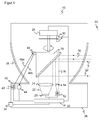
- Fig. 1 shows a schematic sectional view through a laser scanner 10 according to the invention, which is designed in particular as a distance-measuring safety laser scanner.
- a light emitter 12 such as a laser in the form of an edge emitter or a VCSEL, emits a light signal, for example in the form of short light pulses or periodically amplitude modulated light.
- the transmitted light is collimated by a transmission optical system 14 to an emitted light beam 16, which is directed via a movable deflection unit 18 in a monitoring area 20 and there remitted or reflected by an optionally existing object.
- a portion of this light returns to the laser scanner 10 as incidental remitted light beam 22 and is deflected by the deflection unit 18 to a receiving optics 24 and thence focused onto a light receiver 26, such as a photodiode or Avalanche Photo Diode (APD).
- a light receiver 26 such as a photodiode or Avalanche Photo Diode (APD).
- the deflection unit 18 may be designed as a vibrating mirror, but is usually a rotating mirror, which rotates continuously by driving a motor 28.
- the respective angular position of the deflection unit 18 is detected by an encoder 30.
- the light beam 16 generated by the light emitter 12 thus passes over the monitoring area 20 generated by the movement. If a remitted light beam 22 from the monitoring area 20 is received by the light receiver 26, the angular position of the deflection unit 18 can be adjusted to the angular position of the object by means of the encoder 30 be closed in the monitoring area 20.
- the light transit time from emission of the light beam 16 to the reception of the remitted light beam 22 after reflection on the object in the surveillance area 20 is determined.
- all the light transit time methods are conceivable. From the light transit time, the distance of the object from the laser scanner 10 is closed by using the speed of light. This evaluation takes place in an evaluation unit 32, which is connected to the light transmitter 12, the light receiver 26, the motor 28 and the encoder 30.
- Two-dimensional polar coordinates of all objects in the monitoring area 20 are then available via the angle and the distance.
- two-dimensional protective fields can thus be defined, in which impermissible objects such as operators or their body parts are not permitted to intervene.
- a safety-related shutdown signal is output via a safe output (OSSD, output signal switching device) in order, for example, to stop a monitored dangerous machine or to move it to a safe position.
- measurement data is output via the output 34, especially if the laser scanner 10 is not a safety laser scanner and accordingly monitors no protective fields.
- All said functional components are arranged in a housing 36, which has a peripheral windshield 38 in the region of the light exit and light entry.
- the windscreen 38 is often, but not necessarily designed as a rotational body and must not necessarily extend over 360 ° in both cases, so that then a certain angular range remains as a dead zone.
- the windshield 38 has an inwardly directed contour, which in the example of FIG. 1 is curved like a cup. Another curvature and even a straight contour are also conceivable, which then leads to the overall shape of a truncated cone.
- a base 40 In the lower part of the windshield 38 is completed by a base 40, which returns the radius again, which decreases above because of the inwardly directed contour.
- test light transmitter 42 Under this base 40, a test light transmitter 42 and a test light receiver 44 are arranged.
- the test light transmitter 42 is an arbitrary light source, the spectrum of which differs from the light emitter 12, preferably to avoid stray light, but tests the front screen 38 for transmission in a relevant wavelength range.
- the test light receiver may be a simple photodiode, but in some embodiments, spatial resolution is beneficial. Further pairs of test light transmitters and test light receivers are preferably distributed around the circumference of the front screen 38, but in FIG. 1 not shown.
- the test light of the test light transmitter 42 first emerges on a test light path 46a-b through the pedestal 40 and then passes the front screen 38 inside the laser scanner 10.
- test light reflector 48 attached to the deflector 18 and returns to completion of the test light path 46a-b with re-irradiation of the front screen 38 and socket 40 back to the test light receiver 44.
- the test light receiver 44 is inside, so that the front screen 38 is only once irradiated.
- the evaluation unit 32 can check, for example, by comparison with a desired level, whether the front screen 38 is impaired in its light transmission at the piercing points of the test light path 46a-b. This makes possible a test for homogeneous contamination or the presence of shading objects on the windshield 38.
- a safety-related shutdown is triggered when a fault is detected that no longer guarantees safe operation.
- a sensor not used in safety technology could instead only display a maintenance request.
- the test light reflector 48 completes the rotational movement of the deflection unit 18.
- the test light path 46a-b is also dynamic because one of the end points moves with the test light reflector 48.
- the windshield 38 can be monitored so not only punctually, but in the course of the rotational movement over an entire range on their transmission properties.
- the evaluation unit 32 must take the rotational movement into account when activating the test channels formed by the test light transmitters 42 and test light receivers 44 via the test light reflector 48.
- the test channels can also be used to obtain information about the angular position of the deflection unit 18.
- Coarse angle information is already included in the position of the pair of test light transmitters 42 and test light receivers 44, each of which can currently generate a test light signal via the test light reflector 48.
- the intensity and impingement point of the test light on the test light receiver 44 can also vary with the respective position of the test light reflector 48.
- a more accurate angle information can also be detected with which, for example, the measurement information of the encoder 30 can be checked for plausibility or even the encoder 30 can be replaced.
- the laser scanner 10 according to FIG. 1 has a biaxial arrangement in which the emitted light beam 16 extends adjacent to the incident remitted light beam 22. But that is only an example.
- a transmission check of the windshield 38 via a co-moving test light reflector 48 is also in each other Construction of a corresponding optoelectronic sensor with periodically moving deflection possible.
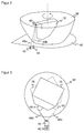
- FIG. 2 shows a further three-dimensional view of the front screen 38 with base 40 and the deflection unit 18 with the co-moving test light reflector 48. For clarity, again only a test channel with a pair of a test light transmitter 42 and a test light receiver 44 is shown.
- FIG. 3 is a complementary associated plan view at two exemplary angular positions of the deflection unit 18 and thus also of the test light reflector 48, which are respectively shown by solid and dashed lines.
- Rotation of the deflector 18 displaces the test light path 46a-b and the piercing point through the windshield 38 travels over an extended area.
- the transmission test is therefore carried out in the same test channel not only at a fixed azimuth angle, but over an entire azimuth angle range.
- a smaller number of test channels, each with a static pair of test light transmitter 42 and test light receiver 44, is sufficient to test the front screen 38 for all relevant azimuth angles.
- the test light reflector 48 preferably has retroreflective properties. This will make the test light as in FIG. 3 Recognized at different azimuth angles back to the test light receiver 44.
- the test light reflector 48 is for this purpose preferably designed as a retroreflector or arrangement of multiple retroreflectors. Alternatively, a contoured mirror may be used which at least partially reflects light from different angles of incidence by its inclination or with multiple reflections. Even with a simple mirror surface as a test light reflector 48, a transmission test is possible. There is more freedom in the arrangement of test light transmitter 42 and test light receiver 44, but only a smaller portion of the windscreen 38 is tested.
- FIG. 4 shows a simplified sectional view of the windshield 38 and a test channel in another embodiment.
- the test light reflector 48 has two or more partial reflectors 48a-b, which are arranged one above the other and / or tilted differently. While the co-movement of the test light reflector 48 provides for scanning the windshield 38 over an azimuth angle range, enable Partial reflectors 48a-b also scan over different polar angles or height ranges. It is usually sufficient to generate only a total summary signal of all partial reflectors 48a-b in the test light receiver 44 since this already identifies a safety-critical impairment. However, if a contamination or a shading object is to be located, the test light receiver 44 can also be designed to be spatially resolving.
- test light reflector 48 By the co-movement of the test light reflector 48, the required number of test channels can already be significantly reduced. As explained in the introduction, with a biaxial construction of the laser scanner 10, as in FIG. 1 additionally be ensured that a shading object does not obscure the near zone of the receiving optics 24.
- FIG. 5 shows a receiving lens 50, which can be used in the receiving optics 24 or as receiving optics 24 and in which the signal from objects in the vicinity can no longer be completely covered by individual small shading objects.
- the lens 50 has a main part 52 which is convex or plano-convex. Overall, therefore, it is a converging lens for focusing the remitted light beam 22. On the right in FIG. 5 the lens is cut off to bring the transmit and receive paths closer together. This truncation is not mandatory.
- the lens 50 has an extended, here divided into two parting zones 54a-b.
- a near zone per se is known and serves, as described in the introduction, to increase the signal dynamics for short distances by other bundling properties than the main part 52. Due to the spatial separation into two or more near zones 54a-b, it is additionally achieved that the signal in the near range can no longer be completely covered by individual small objects. Therefore, an improved robustness against punctiform soiling and tampering is achieved up to a defined maximum size of the interfering or manipulating object.
- a shared near zone 54a-b is just one example of a distribution of the near zone to a larger area.
- the described advantage can also be achieved when otherwise extends the near zone to an area that can not be obscured by small objects.
- Another example is therefore an annular near zone near the outer edge of the receiving lens 50.
- test light transmitters 42 and test light receivers 44 are concerned with a moving or co-rotating test light reflector 48 and static test light transmitters 42 and test light receivers 44. It is also conceivable to accommodate the test light transmitters 42 and test light receivers 44 on a kind of balcony of the deflection unit 18 and thus also to turn them. Then, a single pair of test light transmitter 42 and test light receiver 44 is sufficient to scan the windshield 38 in the course of the rotational movement in all azimuth angles.
- test light paths are reflexively formed of test light transmitter, test light reflector and test light receiver.
- Each of these elements can be static or co-moving, resulting in a total of eight combinations.
- the test light transmitter moves relative to the test light receiver. This is not a useful configuration for a reflective test light path. Instead, the test light emitters and the test light receivers should either be both static or both co-moving so that they are always static with each other and often side by side. In two of the remaining combinations, the test light reflector moves with the deflection unit. If the test light transmitter and the test light receiver are static, this corresponds to the embodiments explained in detail above with reference to the figures.
- test light reflector is static. This then corresponds to the procedure according to the introductory mentioned also with static test light transmitter and test light receiver DE 43 45 446 C2 and with co-moving test light transmitter and test light receiver according to the aforementioned EP 2 237 065 A1 ,
- test light paths are formed directly, ie without test light reflector.
- the pair of test light emitters and test light receivers are aligned directly with each other through the front screen, and an element is located with respect to the windscreen inside and one outside.
- an element is located with respect to the windscreen inside and one outside.
- the test light transmitter should be moved, otherwise the test light receiver looks outward and thus also detects extraneous light.
- the deflection unit could also have a kind of balcony which extends under the base of the windshield. In this way test light transmitter and test light receiver can be moved, and it suffices a single test channel.
- this balcony poses a major mechanical challenge to avoid adverse effects on the deflector due to imbalance.
- test light paths are formed with the actual scan beam of the light emitter 12.
- the light transmitter 12 thus also acts as a test light transmitter.
Landscapes
- Physics & Mathematics (AREA)
- Engineering & Computer Science (AREA)
- General Physics & Mathematics (AREA)
- Computer Networks & Wireless Communication (AREA)
- Radar, Positioning & Navigation (AREA)
- Remote Sensing (AREA)
- Electromagnetism (AREA)
- Chemical & Material Sciences (AREA)
- Analytical Chemistry (AREA)
- Life Sciences & Earth Sciences (AREA)
- Health & Medical Sciences (AREA)
- Biochemistry (AREA)
- General Health & Medical Sciences (AREA)
- Immunology (AREA)
- Pathology (AREA)
- Optical Radar Systems And Details Thereof (AREA)
- Geophysics And Detection Of Objects (AREA)
Applications Claiming Priority (1)
| Application Number | Priority Date | Filing Date | Title |
|---|---|---|---|
| DE102015105264.4A DE102015105264B4 (de) | 2015-04-08 | 2015-04-08 | Optoelektronischer Sensor und Verfahren zur Transmissionsüberwachung einer Frontscheibe |
Publications (2)
| Publication Number | Publication Date |
|---|---|
| EP3078985A1 true EP3078985A1 (fr) | 2016-10-12 |
| EP3078985B1 EP3078985B1 (fr) | 2018-03-14 |
Family
ID=55588135
Family Applications (1)
| Application Number | Title | Priority Date | Filing Date |
|---|---|---|---|
| EP16161687.5A Active EP3078985B1 (fr) | 2015-04-08 | 2016-03-22 | Capteur optoelectronique et procede de surveillance de transmission d'un disque frontal |
Country Status (3)
| Country | Link |
|---|---|
| US (1) | US9810626B2 (fr) |
| EP (1) | EP3078985B1 (fr) |
| DE (1) | DE102015105264B4 (fr) |
Cited By (3)
| Publication number | Priority date | Publication date | Assignee | Title |
|---|---|---|---|---|
| WO2024003196A1 (fr) * | 2022-06-28 | 2024-01-04 | Bea Sa | Capteur optique comprenant une fenêtre et une unité de surveillance de fenêtre et procédé de surveillance de la transparence de la fenêtre |
| EP4390443A1 (fr) * | 2022-12-19 | 2024-06-26 | Leuze electronic GmbH + Co. KG | Surveillance des capteurs de contrôle d'un capteur optique |
| EP4468026A1 (fr) | 2023-05-25 | 2024-11-27 | Sick Ag | Capteur optoélectronique et procédé de mesure de l'encrassement d'une vitre frontale |
Families Citing this family (11)
| Publication number | Priority date | Publication date | Assignee | Title |
|---|---|---|---|---|
| DE102017101945B4 (de) * | 2017-02-01 | 2026-02-12 | OSRAM Opto Semiconductors Gesellschaft mit beschränkter Haftung | Messanordnung mit einem optischen Sender und einem optischen Empfänger |
| DE102017103791B4 (de) | 2017-02-23 | 2021-09-30 | Sick Ag | Optoelektronischer Sensor und Verfahren zur Erfassung von Objekten |
| KR102299264B1 (ko) | 2019-01-16 | 2021-09-07 | 삼성전자주식회사 | 라이다 장치 |
| DK3862780T3 (da) * | 2020-02-07 | 2022-02-14 | Sick Ag | Sikkerhedslaserscanner og fremgangsmåde til overvågning af en frontrude |
| DE102020120908A1 (de) | 2020-08-07 | 2022-02-10 | Sick Ag | Optoelektronischer Sensor und Verfahren zur Frontscheibenüberwachung |
| EP3951427A1 (fr) | 2020-08-07 | 2022-02-09 | Sick Ag | Capteur optoélectronique et procédé de surveillance de par-brise |
| DE102021108318B4 (de) * | 2021-04-01 | 2024-03-14 | Sick Ag | Optoelektronischer Sensor |
| EP4086661A1 (fr) | 2021-05-04 | 2022-11-09 | Sick Ag | Capteur optoélectronique et procédé de surveillance d'une vitre avant |
| DE102022116100A1 (de) | 2022-06-28 | 2023-12-28 | Bea Sa | Sensor |
| JP2024053957A (ja) * | 2022-10-04 | 2024-04-16 | ソニーセミコンダクタソリューションズ株式会社 | 光検出装置 |
| DE102023126511A1 (de) * | 2023-09-28 | 2025-04-03 | Universität Kassel, Körperschaft des öffentlichen Rechts | Lidar-Messvorrichtung mit Selbstdiagnosefähigkeit |
Citations (8)
| Publication number | Priority date | Publication date | Assignee | Title |
|---|---|---|---|---|
| DE9321155U1 (de) * | 1992-12-08 | 1996-06-27 | Sick Optik Elektronik Erwin | Laserabstandsermittlungsvorrichtung |
| WO2007031359A1 (fr) * | 2005-09-13 | 2007-03-22 | Robert Bosch Gmbh | Appareil de mesure electrooptique |
| US20080158555A1 (en) * | 2006-12-28 | 2008-07-03 | Hokuyo Automatic Co., Ltd. | Optical window contamination detecting device for optical apparatus |
| DE202009004397U1 (de) * | 2009-03-28 | 2010-08-12 | Sick Ag | Sicherheitsvorrichtung |
| EP2237065A1 (fr) | 2009-03-31 | 2010-10-06 | Pepperl + Fuchs GmbH | Capteur optique selon le principe de temps de vol |
| EP2447733A1 (fr) * | 2010-10-29 | 2012-05-02 | Sick AG | Capteur optoélectronique |
| EP2482094A1 (fr) * | 2011-01-31 | 2012-08-01 | Sick AG | Capteur optoélectronique mesurant l'éloignement et procédé de détection d'objet |
| EP2508914A1 (fr) * | 2011-04-05 | 2012-10-10 | Sick AG | Dispositif de détection optique |
Family Cites Families (3)
| Publication number | Priority date | Publication date | Assignee | Title |
|---|---|---|---|---|
| DE19756541A1 (de) * | 1997-12-18 | 1999-06-24 | Sick Ag | Opto-elektronischer Sensor |
| FR2817339B1 (fr) * | 2000-11-24 | 2004-05-14 | Mensi | Dispositif de relevement tridimensionnel d'une scene a emission laser |
| US8692983B1 (en) * | 2011-09-13 | 2014-04-08 | Rockwell Collins, Inc. | Optical, laser-based, or lidar measuring systems and method |
-
2015
- 2015-04-08 DE DE102015105264.4A patent/DE102015105264B4/de active Active
-
2016
- 2016-03-22 EP EP16161687.5A patent/EP3078985B1/fr active Active
- 2016-04-07 US US15/092,991 patent/US9810626B2/en active Active
Patent Citations (9)
| Publication number | Priority date | Publication date | Assignee | Title |
|---|---|---|---|---|
| DE9321155U1 (de) * | 1992-12-08 | 1996-06-27 | Sick Optik Elektronik Erwin | Laserabstandsermittlungsvorrichtung |
| DE4345446C2 (de) | 1992-12-08 | 1998-07-30 | Sick Ag | Laserabstandsermittlungsvorrichtung |
| WO2007031359A1 (fr) * | 2005-09-13 | 2007-03-22 | Robert Bosch Gmbh | Appareil de mesure electrooptique |
| US20080158555A1 (en) * | 2006-12-28 | 2008-07-03 | Hokuyo Automatic Co., Ltd. | Optical window contamination detecting device for optical apparatus |
| DE202009004397U1 (de) * | 2009-03-28 | 2010-08-12 | Sick Ag | Sicherheitsvorrichtung |
| EP2237065A1 (fr) | 2009-03-31 | 2010-10-06 | Pepperl + Fuchs GmbH | Capteur optique selon le principe de temps de vol |
| EP2447733A1 (fr) * | 2010-10-29 | 2012-05-02 | Sick AG | Capteur optoélectronique |
| EP2482094A1 (fr) * | 2011-01-31 | 2012-08-01 | Sick AG | Capteur optoélectronique mesurant l'éloignement et procédé de détection d'objet |
| EP2508914A1 (fr) * | 2011-04-05 | 2012-10-10 | Sick AG | Dispositif de détection optique |
Cited By (4)
| Publication number | Priority date | Publication date | Assignee | Title |
|---|---|---|---|---|
| WO2024003196A1 (fr) * | 2022-06-28 | 2024-01-04 | Bea Sa | Capteur optique comprenant une fenêtre et une unité de surveillance de fenêtre et procédé de surveillance de la transparence de la fenêtre |
| BE1030617B1 (fr) * | 2022-06-28 | 2024-05-17 | Bea Sa | Capteur optique avec une fenêtre et une unité de surveillance de fenêtre et procédé de surveillance de la transparence de la fenêtre |
| EP4390443A1 (fr) * | 2022-12-19 | 2024-06-26 | Leuze electronic GmbH + Co. KG | Surveillance des capteurs de contrôle d'un capteur optique |
| EP4468026A1 (fr) | 2023-05-25 | 2024-11-27 | Sick Ag | Capteur optoélectronique et procédé de mesure de l'encrassement d'une vitre frontale |
Also Published As
| Publication number | Publication date |
|---|---|
| US20160299072A1 (en) | 2016-10-13 |
| DE102015105264B4 (de) | 2026-07-30 |
| US9810626B2 (en) | 2017-11-07 |
| EP3078985B1 (fr) | 2018-03-14 |
| DE102015105264A1 (de) | 2016-10-13 |
Similar Documents
| Publication | Publication Date | Title |
|---|---|---|
| EP3078985B1 (fr) | Capteur optoelectronique et procede de surveillance de transmission d'un disque frontal | |
| EP2927711B1 (fr) | Lecteur laser et procédé de saisie sécurisée d'objets | |
| EP2642314B1 (fr) | Capteur optoélectronique et procédé destiné à tester la perméabilité à la lumière d'une vitre frontale | |
| EP2378309B1 (fr) | Capteur optoélectronique et procédé de production d'informations sur des objets dans une zone de surveillance | |
| EP2124069B1 (fr) | Système LIDAR omnidirectionnel | |
| EP2482094B1 (fr) | Capteur optoélectronique mesurant l'éloignement et procédé de détection d'objet | |
| EP3862780B1 (fr) | Balayeur laser de sécurité et procédé de surveillance de vitre frontale | |
| EP3699638B1 (fr) | Capteur optoélectronique et procédé de détection d'un objet | |
| EP3163322B1 (fr) | Scanner laser et procédé de vérification de sa capacité de fonctionnement | |
| EP2381268B1 (fr) | Scanner laser de sécurité | |
| EP3388857B1 (fr) | Dispositif de balayage laser et procédé de vérification de la capacité de fonctionnement | |
| EP2447733A1 (fr) | Capteur optoélectronique | |
| EP2375266B1 (fr) | Capteur optoélectronique et procédé de sécurisation | |
| EP3220164B1 (fr) | Procédé de fonctionnement d'un capteur écartométrique de surveillance et capteur écartométrique de surveillance | |
| EP3078984B1 (fr) | Capteur optoelectronique et procede de detection d'objets dans une zone de surveillance | |
| EP2354806B1 (fr) | Capteur optoélectronique | |
| EP3330741B1 (fr) | Capteur optoélectronique et procédé de détection d'objets dans une zone de détection | |
| EP2375264B1 (fr) | Scanner de sécurité avec surveillance d'encrassement | |
| EP4086661A1 (fr) | Capteur optoélectronique et procédé de surveillance d'une vitre avant | |
| EP3699637A1 (fr) | Capteur optoélectronique et procédé de détection d'un objet | |
| EP4071503B1 (fr) | Capteur optoélectronique et procédé de détection des objets | |
| EP4067939B1 (fr) | Capteur optoélectronique | |
| EP4109127B1 (fr) | Capteur optoélectronique et procédé de détection des objets | |
| DE202012101007U1 (de) | Optoelektronischer Sensor | |
| DE102017103791B4 (de) | Optoelektronischer Sensor und Verfahren zur Erfassung von Objekten |
Legal Events
| Date | Code | Title | Description |
|---|---|---|---|
| PUAI | Public reference made under article 153(3) epc to a published international application that has entered the european phase |
Free format text: ORIGINAL CODE: 0009012 |
|
| 17P | Request for examination filed |
Effective date: 20160829 |
|
| AK | Designated contracting states |
Kind code of ref document: A1 Designated state(s): AL AT BE BG CH CY CZ DE DK EE ES FI FR GB GR HR HU IE IS IT LI LT LU LV MC MK MT NL NO PL PT RO RS SE SI SK SM TR |
|
| AX | Request for extension of the european patent |
Extension state: BA ME |
|
| 17Q | First examination report despatched |
Effective date: 20161125 |
|
| GRAP | Despatch of communication of intention to grant a patent |
Free format text: ORIGINAL CODE: EPIDOSNIGR1 |
|
| INTG | Intention to grant announced |
Effective date: 20171123 |
|
| GRAS | Grant fee paid |
Free format text: ORIGINAL CODE: EPIDOSNIGR3 |
|
| GRAA | (expected) grant |
Free format text: ORIGINAL CODE: 0009210 |
|
| AK | Designated contracting states |
Kind code of ref document: B1 Designated state(s): AL AT BE BG CH CY CZ DE DK EE ES FI FR GB GR HR HU IE IS IT LI LT LU LV MC MK MT NL NO PL PT RO RS SE SI SK SM TR |
|
| REG | Reference to a national code |
Ref country code: GB Ref legal event code: FG4D Free format text: NOT ENGLISH |
|
| REG | Reference to a national code |
Ref country code: CH Ref legal event code: EP Ref country code: AT Ref legal event code: REF Ref document number: 979428 Country of ref document: AT Kind code of ref document: T Effective date: 20180315 |
|
| REG | Reference to a national code |
Ref country code: IE Ref legal event code: FG4D Free format text: LANGUAGE OF EP DOCUMENT: GERMAN |
|
| REG | Reference to a national code |
Ref country code: DE Ref legal event code: R096 Ref document number: 502016000682 Country of ref document: DE |
|
| REG | Reference to a national code |
Ref country code: FR Ref legal event code: PLFP Year of fee payment: 3 |
|
| REG | Reference to a national code |
Ref country code: NL Ref legal event code: MP Effective date: 20180314 |
|
| REG | Reference to a national code |
Ref country code: LT Ref legal event code: MG4D |
|
| PG25 | Lapsed in a contracting state [announced via postgrant information from national office to epo] |
Ref country code: HR Free format text: LAPSE BECAUSE OF FAILURE TO SUBMIT A TRANSLATION OF THE DESCRIPTION OR TO PAY THE FEE WITHIN THE PRESCRIBED TIME-LIMIT Effective date: 20180314 Ref country code: LT Free format text: LAPSE BECAUSE OF FAILURE TO SUBMIT A TRANSLATION OF THE DESCRIPTION OR TO PAY THE FEE WITHIN THE PRESCRIBED TIME-LIMIT Effective date: 20180314 Ref country code: CY Free format text: LAPSE BECAUSE OF FAILURE TO SUBMIT A TRANSLATION OF THE DESCRIPTION OR TO PAY THE FEE WITHIN THE PRESCRIBED TIME-LIMIT Effective date: 20180314 Ref country code: NO Free format text: LAPSE BECAUSE OF FAILURE TO SUBMIT A TRANSLATION OF THE DESCRIPTION OR TO PAY THE FEE WITHIN THE PRESCRIBED TIME-LIMIT Effective date: 20180614 Ref country code: FI Free format text: LAPSE BECAUSE OF FAILURE TO SUBMIT A TRANSLATION OF THE DESCRIPTION OR TO PAY THE FEE WITHIN THE PRESCRIBED TIME-LIMIT Effective date: 20180314 |
|
| PG25 | Lapsed in a contracting state [announced via postgrant information from national office to epo] |
Ref country code: BG Free format text: LAPSE BECAUSE OF FAILURE TO SUBMIT A TRANSLATION OF THE DESCRIPTION OR TO PAY THE FEE WITHIN THE PRESCRIBED TIME-LIMIT Effective date: 20180614 Ref country code: GR Free format text: LAPSE BECAUSE OF FAILURE TO SUBMIT A TRANSLATION OF THE DESCRIPTION OR TO PAY THE FEE WITHIN THE PRESCRIBED TIME-LIMIT Effective date: 20180615 Ref country code: RS Free format text: LAPSE BECAUSE OF FAILURE TO SUBMIT A TRANSLATION OF THE DESCRIPTION OR TO PAY THE FEE WITHIN THE PRESCRIBED TIME-LIMIT Effective date: 20180314 Ref country code: LV Free format text: LAPSE BECAUSE OF FAILURE TO SUBMIT A TRANSLATION OF THE DESCRIPTION OR TO PAY THE FEE WITHIN THE PRESCRIBED TIME-LIMIT Effective date: 20180314 Ref country code: SE Free format text: LAPSE BECAUSE OF FAILURE TO SUBMIT A TRANSLATION OF THE DESCRIPTION OR TO PAY THE FEE WITHIN THE PRESCRIBED TIME-LIMIT Effective date: 20180314 |
|
| PG25 | Lapsed in a contracting state [announced via postgrant information from national office to epo] |
Ref country code: MT Free format text: LAPSE BECAUSE OF FAILURE TO SUBMIT A TRANSLATION OF THE DESCRIPTION OR TO PAY THE FEE WITHIN THE PRESCRIBED TIME-LIMIT Effective date: 20180314 |
|
| PG25 | Lapsed in a contracting state [announced via postgrant information from national office to epo] |
Ref country code: AL Free format text: LAPSE BECAUSE OF FAILURE TO SUBMIT A TRANSLATION OF THE DESCRIPTION OR TO PAY THE FEE WITHIN THE PRESCRIBED TIME-LIMIT Effective date: 20180314 Ref country code: RO Free format text: LAPSE BECAUSE OF FAILURE TO SUBMIT A TRANSLATION OF THE DESCRIPTION OR TO PAY THE FEE WITHIN THE PRESCRIBED TIME-LIMIT Effective date: 20180314 Ref country code: ES Free format text: LAPSE BECAUSE OF FAILURE TO SUBMIT A TRANSLATION OF THE DESCRIPTION OR TO PAY THE FEE WITHIN THE PRESCRIBED TIME-LIMIT Effective date: 20180314 Ref country code: PL Free format text: LAPSE BECAUSE OF FAILURE TO SUBMIT A TRANSLATION OF THE DESCRIPTION OR TO PAY THE FEE WITHIN THE PRESCRIBED TIME-LIMIT Effective date: 20180314 Ref country code: NL Free format text: LAPSE BECAUSE OF FAILURE TO SUBMIT A TRANSLATION OF THE DESCRIPTION OR TO PAY THE FEE WITHIN THE PRESCRIBED TIME-LIMIT Effective date: 20180314 Ref country code: EE Free format text: LAPSE BECAUSE OF FAILURE TO SUBMIT A TRANSLATION OF THE DESCRIPTION OR TO PAY THE FEE WITHIN THE PRESCRIBED TIME-LIMIT Effective date: 20180314 |
|
| PG25 | Lapsed in a contracting state [announced via postgrant information from national office to epo] |
Ref country code: SM Free format text: LAPSE BECAUSE OF FAILURE TO SUBMIT A TRANSLATION OF THE DESCRIPTION OR TO PAY THE FEE WITHIN THE PRESCRIBED TIME-LIMIT Effective date: 20180314 Ref country code: CZ Free format text: LAPSE BECAUSE OF FAILURE TO SUBMIT A TRANSLATION OF THE DESCRIPTION OR TO PAY THE FEE WITHIN THE PRESCRIBED TIME-LIMIT Effective date: 20180314 Ref country code: SK Free format text: LAPSE BECAUSE OF FAILURE TO SUBMIT A TRANSLATION OF THE DESCRIPTION OR TO PAY THE FEE WITHIN THE PRESCRIBED TIME-LIMIT Effective date: 20180314 |
|
| REG | Reference to a national code |
Ref country code: BE Ref legal event code: MM Effective date: 20180331 |
|
| REG | Reference to a national code |
Ref country code: DE Ref legal event code: R097 Ref document number: 502016000682 Country of ref document: DE |
|
| REG | Reference to a national code |
Ref country code: IE Ref legal event code: MM4A |
|
| PG25 | Lapsed in a contracting state [announced via postgrant information from national office to epo] |
Ref country code: LU Free format text: LAPSE BECAUSE OF NON-PAYMENT OF DUE FEES Effective date: 20180322 Ref country code: PT Free format text: LAPSE BECAUSE OF FAILURE TO SUBMIT A TRANSLATION OF THE DESCRIPTION OR TO PAY THE FEE WITHIN THE PRESCRIBED TIME-LIMIT Effective date: 20180716 |
|
| PLBE | No opposition filed within time limit |
Free format text: ORIGINAL CODE: 0009261 |
|
| STAA | Information on the status of an ep patent application or granted ep patent |
Free format text: STATUS: NO OPPOSITION FILED WITHIN TIME LIMIT |
|
| PG25 | Lapsed in a contracting state [announced via postgrant information from national office to epo] |
Ref country code: DK Free format text: LAPSE BECAUSE OF FAILURE TO SUBMIT A TRANSLATION OF THE DESCRIPTION OR TO PAY THE FEE WITHIN THE PRESCRIBED TIME-LIMIT Effective date: 20180314 Ref country code: IE Free format text: LAPSE BECAUSE OF NON-PAYMENT OF DUE FEES Effective date: 20180322 Ref country code: MC Free format text: LAPSE BECAUSE OF FAILURE TO SUBMIT A TRANSLATION OF THE DESCRIPTION OR TO PAY THE FEE WITHIN THE PRESCRIBED TIME-LIMIT Effective date: 20180314 |
|
| 26N | No opposition filed |
Effective date: 20181217 |
|
| PG25 | Lapsed in a contracting state [announced via postgrant information from national office to epo] |
Ref country code: BE Free format text: LAPSE BECAUSE OF NON-PAYMENT OF DUE FEES Effective date: 20180331 Ref country code: SI Free format text: LAPSE BECAUSE OF FAILURE TO SUBMIT A TRANSLATION OF THE DESCRIPTION OR TO PAY THE FEE WITHIN THE PRESCRIBED TIME-LIMIT Effective date: 20180314 |
|
| PG25 | Lapsed in a contracting state [announced via postgrant information from national office to epo] |
Ref country code: TR Free format text: LAPSE BECAUSE OF FAILURE TO SUBMIT A TRANSLATION OF THE DESCRIPTION OR TO PAY THE FEE WITHIN THE PRESCRIBED TIME-LIMIT Effective date: 20180314 |
|
| PG25 | Lapsed in a contracting state [announced via postgrant information from national office to epo] |
Ref country code: HU Free format text: LAPSE BECAUSE OF FAILURE TO SUBMIT A TRANSLATION OF THE DESCRIPTION OR TO PAY THE FEE WITHIN THE PRESCRIBED TIME-LIMIT; INVALID AB INITIO Effective date: 20160322 Ref country code: MK Free format text: LAPSE BECAUSE OF NON-PAYMENT OF DUE FEES Effective date: 20180314 |
|
| PG25 | Lapsed in a contracting state [announced via postgrant information from national office to epo] |
Ref country code: IS Free format text: LAPSE BECAUSE OF FAILURE TO SUBMIT A TRANSLATION OF THE DESCRIPTION OR TO PAY THE FEE WITHIN THE PRESCRIBED TIME-LIMIT Effective date: 20180714 |
|
| GBPC | Gb: european patent ceased through non-payment of renewal fee |
Effective date: 20200322 |
|
| PG25 | Lapsed in a contracting state [announced via postgrant information from national office to epo] |
Ref country code: GB Free format text: LAPSE BECAUSE OF NON-PAYMENT OF DUE FEES Effective date: 20200322 |
|
| REG | Reference to a national code |
Ref country code: AT Ref legal event code: MM01 Ref document number: 979428 Country of ref document: AT Kind code of ref document: T Effective date: 20210322 |
|
| PG25 | Lapsed in a contracting state [announced via postgrant information from national office to epo] |
Ref country code: AT Free format text: LAPSE BECAUSE OF NON-PAYMENT OF DUE FEES Effective date: 20210322 |
|
| REG | Reference to a national code |
Ref country code: CH Ref legal event code: U11 Free format text: ST27 STATUS EVENT CODE: U-0-0-U10-U11 (AS PROVIDED BY THE NATIONAL OFFICE) Effective date: 20260401 |
|
| PGFP | Annual fee paid to national office [announced via postgrant information from national office to epo] |
Ref country code: DE Payment date: 20260320 Year of fee payment: 11 |
|
| PGFP | Annual fee paid to national office [announced via postgrant information from national office to epo] |
Ref country code: FR Payment date: 20260324 Year of fee payment: 11 |
|
| PGFP | Annual fee paid to national office [announced via postgrant information from national office to epo] |
Ref country code: IT Payment date: 20260331 Year of fee payment: 11 |
|
| PGFP | Annual fee paid to national office [announced via postgrant information from national office to epo] |
Ref country code: CH Payment date: 20260401 Year of fee payment: 11 |