EP3663865B1 - Procede de realisation d'un axe de balancier - Google Patents
Procede de realisation d'un axe de balancier Download PDFInfo
- Publication number
- EP3663865B1 EP3663865B1 EP19213301.5A EP19213301A EP3663865B1 EP 3663865 B1 EP3663865 B1 EP 3663865B1 EP 19213301 A EP19213301 A EP 19213301A EP 3663865 B1 EP3663865 B1 EP 3663865B1
- Authority
- EP
- European Patent Office
- Prior art keywords
- shaft
- machining
- laser
- shaping
- alloy
- Prior art date
- Legal status (The legal status is an assumption and is not a legal conclusion. Google has not performed a legal analysis and makes no representation as to the accuracy of the status listed.)
- Active
Links
Images

Classifications
-
- G—PHYSICS
- G04—HOROLOGY
- G04D—APPARATUS OR TOOLS SPECIALLY DESIGNED FOR MAKING OR MAINTAINING CLOCKS OR WATCHES
- G04D3/00—Watchmakers' or watch-repairers' machines or tools for working materials
- G04D3/0074—Watchmakers' or watch-repairers' machines or tools for working materials for treatment of the material, e.g. surface treatment
- G04D3/0089—Watchmakers' or watch-repairers' machines or tools for working materials for treatment of the material, e.g. surface treatment for components of the regulating mechanism, e.g. coil springs
-
- G—PHYSICS
- G04—HOROLOGY
- G04B—MECHANICALLY-DRIVEN CLOCKS OR WATCHES; MECHANICAL PARTS OF CLOCKS OR WATCHES IN GENERAL; TIME PIECES USING THE POSITION OF THE SUN, MOON OR STARS
- G04B17/00—Mechanisms for stabilising frequency
- G04B17/04—Oscillators acting by spring tension
- G04B17/06—Oscillators with hairsprings, e.g. balance
- G04B17/063—Balance construction
-
- G—PHYSICS
- G04—HOROLOGY
- G04B—MECHANICALLY-DRIVEN CLOCKS OR WATCHES; MECHANICAL PARTS OF CLOCKS OR WATCHES IN GENERAL; TIME PIECES USING THE POSITION OF THE SUN, MOON OR STARS
- G04B17/00—Mechanisms for stabilising frequency
- G04B17/32—Component parts or constructional details, e.g. collet, stud, virole or piton
-
- G—PHYSICS
- G04—HOROLOGY
- G04B—MECHANICALLY-DRIVEN CLOCKS OR WATCHES; MECHANICAL PARTS OF CLOCKS OR WATCHES IN GENERAL; TIME PIECES USING THE POSITION OF THE SUN, MOON OR STARS
- G04B18/00—Mechanisms for setting frequency
- G04B18/08—Component parts or constructional details
-
- B—PERFORMING OPERATIONS; TRANSPORTING
- B23—MACHINE TOOLS; METAL-WORKING NOT OTHERWISE PROVIDED FOR
- B23K—SOLDERING OR UNSOLDERING; WELDING; CLADDING OR PLATING BY SOLDERING OR WELDING; CUTTING BY APPLYING HEAT LOCALLY, e.g. FLAME CUTTING; WORKING BY LASER BEAM
- B23K2103/00—Materials to be soldered, welded or cut
- B23K2103/08—Non-ferrous metals or alloys
-
- B—PERFORMING OPERATIONS; TRANSPORTING
- B23—MACHINE TOOLS; METAL-WORKING NOT OTHERWISE PROVIDED FOR
- B23K—SOLDERING OR UNSOLDERING; WELDING; CLADDING OR PLATING BY SOLDERING OR WELDING; CUTTING BY APPLYING HEAT LOCALLY, e.g. FLAME CUTTING; WORKING BY LASER BEAM
- B23K2103/00—Materials to be soldered, welded or cut
- B23K2103/18—Dissimilar materials
- B23K2103/26—Alloys of Nickel and Cobalt and Chromium
-
- B—PERFORMING OPERATIONS; TRANSPORTING
- B23—MACHINE TOOLS; METAL-WORKING NOT OTHERWISE PROVIDED FOR
- B23K—SOLDERING OR UNSOLDERING; WELDING; CLADDING OR PLATING BY SOLDERING OR WELDING; CUTTING BY APPLYING HEAT LOCALLY, e.g. FLAME CUTTING; WORKING BY LASER BEAM
- B23K26/00—Working by laser beam, e.g. welding, cutting or boring
- B23K26/36—Removing material
-
- C—CHEMISTRY; METALLURGY
- C22—METALLURGY; FERROUS OR NON-FERROUS ALLOYS; TREATMENT OF ALLOYS OR NON-FERROUS METALS
- C22C—ALLOYS
- C22C19/00—Alloys based on nickel or cobalt
- C22C19/03—Alloys based on nickel or cobalt based on nickel
- C22C19/05—Alloys based on nickel or cobalt based on nickel with chromium
- C22C19/051—Alloys based on nickel or cobalt based on nickel with chromium and Mo or W
- C22C19/055—Alloys based on nickel or cobalt based on nickel with chromium and Mo or W with the maximum Cr content being at least 20% but less than 30%
-
- C—CHEMISTRY; METALLURGY
- C22—METALLURGY; FERROUS OR NON-FERROUS ALLOYS; TREATMENT OF ALLOYS OR NON-FERROUS METALS
- C22C—ALLOYS
- C22C19/00—Alloys based on nickel or cobalt
- C22C19/03—Alloys based on nickel or cobalt based on nickel
- C22C19/05—Alloys based on nickel or cobalt based on nickel with chromium
- C22C19/051—Alloys based on nickel or cobalt based on nickel with chromium and Mo or W
- C22C19/056—Alloys based on nickel or cobalt based on nickel with chromium and Mo or W with the maximum Cr content being at least 10% but less than 20%
-
- C—CHEMISTRY; METALLURGY
- C22—METALLURGY; FERROUS OR NON-FERROUS ALLOYS; TREATMENT OF ALLOYS OR NON-FERROUS METALS
- C22C—ALLOYS
- C22C19/00—Alloys based on nickel or cobalt
- C22C19/03—Alloys based on nickel or cobalt based on nickel
- C22C19/05—Alloys based on nickel or cobalt based on nickel with chromium
- C22C19/058—Alloys based on nickel or cobalt based on nickel with chromium without Mo and W
Definitions
- the present invention relates to the field of watchmaking. It concerns, more particularly, a method for producing a balance shaft.
- the balance spring In a mechanical watch movement, the balance spring is an important element in determining the regularity of the rate.
- the balance spring is assembled on a shaft, called the balance staff, pivoting in bearings.
- the quality of the pivoting has a great influence on the performance of the movement, in terms of precision, efficiency and durability in particular.
- balance shafts are particularly complex. Indeed, the shaft is machined from a bar, the material of which must be soft enough to be machined precisely and quickly, without causing premature wear of the cutting tools. But the areas interacting with the bearings, called pivots, must also be hard enough to withstand wear during operation. In addition, the surface condition of the pivots must be particularly worked and is currently obtained by rolling operations, which require a material with a hardness of at least 600Hv.
- the document EP2757423 reveals such a process for manufacturing a watch axis.
- the material chosen must therefore be easily machined, and then be able to be hardened by quenching or tempering treatments.
- the machinability of a material can be directly correlated to its specific cutting force, measured by manufacturers by the parameter Kc, generally given in N/mm 2 or MPa.
- Carbon martensitic steels including lead and manganese sulfides are generally used to improve their machinability.
- a steel of this type used in watchmaking is known under the reference 20AP.
- the present invention aims to change the paradigm and aims to propose a new method for producing a watch axis, particularly a balance axis.
- FIG. 1 represents the geometries of a balance shaft during its production using a traditional process
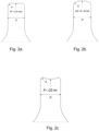
- Figures 2a, 2b and 2c propose balance shaft geometries produced by the method according to the invention.
- a very large amount of energy is applied to the workpiece for a short period of time. Melting or thermal changes do not occur because the material is vaporized instantly.
- the laser is rotated with what is called a trepanning optic.
- Beams with different angles can be sent to the workpiece, automatically changing the rotation diameter and the incidence angle.
- the figure 2 gives three possibilities, respectively to Figures 2a, 2b and 2c .
- the end of the pivot illustrated in 2a is flat. It is described as a right circular cylinder with a diameter D between 50 and 100 ⁇ m (axial symmetry).
- the base of this cylinder has a 90° circular arc with a radius A, between 5 and 25 ⁇ m, starting from the generator of the cylinder. Tangentially and continuously, a radius of curvature R greater than 0.5 mm extends the radius A to the center of the base of the cylinder.
- the end of the pivot illustrated in 2b is convex. It is described as a right circular cylinder with a diameter D of between 50 and 100 ⁇ m (axial symmetry).
- the base of this cylinder has a 90° arc of a circle, with a radius A of between 5 and 25 ⁇ m, starting from the generator of the cylinder.
- a radius of curvature R of between 0.1 and 0.5 mm, more generally between D/2 and 0.5 mm, extends the radius A to the center of the base of the cylinder.
- the end of the pivot illustrated in 2c is concave. It is described as a right circular cylinder with a diameter D of between 50 and 100 ⁇ m (axial symmetry).
- the base of this cylinder has a 90° arc of a circle, with a radius A of between 5 and 25 ⁇ m, starting from the generator of the cylinder.
- a radius of curvature R less than -D/2, preferably less than -0.35 mm extends the radius A to the center of the base of the cylinder.
- this laser bar turning technology made it possible to obtain very good process control and manufacture parts in the dimensions used for watch pivots, with not only very reduced tolerances but also remarkable surface conditions.
- the diameter of the axis at the pivot is approximately 50 ⁇ m and the tolerance is of the order of ⁇ m.
- the surface conditions obtained are better than those obtained after conventional turning.
- a roughness Ra of between 0.025 and 0.1 ⁇ m is measured after laser machining, while it is 0.2 ⁇ m after conventional turning.
- the quality of the surface condition makes it possible to do without subsequent rolling.
- a simple tribological finishing/polishing step is required to further refine the surface condition.
- This type of operation is carried out in bulk, by stirring in a medium loaded with abrasive particles. A large number of parts can therefore be treated very efficiently. No change in geometry is observed during this operation, but only a uniform reduction in dimensions, of a few ⁇ m, depending on the duration of the operation.
- the method according to the invention also relates to the manufacture of a homogeneous balance shaft made of such a non-magnetic alloy.
- the term "homogeneous" means that the material has the same mechanical properties everywhere. Although this is not excluded from the protection, the shaft manufactured according to the method of the invention does not need to receive an external coating to modify its tribological properties.
- the alloys used may be an Inconel 718.
- the alloy comprises between 50 and 55% Nickel, between 17 and 21% Chromium, between 2.8 and 3.3% Molybdenum, between 4.75 and 5.50% Niobium, between 0 and 1.0% Cobalt, between 0 and 0.35% Manganese, between 0 and 0.30% Copper, between 0.20 and 0.80% Aluminum, between 0.65 and 1.15% Titanium, between 0 and 0.35% Silicon, between 0 and 0.08% Carbon, between 0 and 0.015% Sulfur, between 0 and 0.015% Phosphorus, and between 0 and 0.006% Boron, and the balance of Iron.
- different materials with a specific cutting force greater than or equal to 2400 N/mm 2 can be used.
- the selected alloys can optionally be heat treated before being shaped, for example to modify certain properties, such as their hardness. These heat treatments, called aging for this type of alloy, are carried out before laser machining, which avoids any dimensional changes that may occur during heat treatments.
- alloys mentioned being particularly hard, possibly after an ad-hoc heat treatment, it is therefore possible to do without hardening steps generally implemented after traditional machining. Indeed, with traditional bar turning, heat treatment operations such as quenching or tempering are carried out after machining, which requires taking into account the thermal stresses and deformations undergone.
- a simple tribological finishing or polishing step is preferably carried out, while maintaining the defined geometry, that is to say by maintaining the angles or radii, a simple contraction by regular material removal can be observed. The process is therefore much better controlled.
- pivots are shaped during the turning operation. All the geometric characteristics of the axis, including the pivots, are well realized with an extremely low dispersion. The dimensions obtained take into account, where applicable, the removal of material related to a finishing step, such as polishing or other.
- axles can be used without the addition of an external coating. This results in axles that are homogeneous in terms of material and properties.
- the laser can work along the entire length of the shaft, except for the pivot end that connects the shaft to the bar.
- all areas of the shaft can be shaped, gradually refining the surface finish.
- the laser makes the shaft by working its entire length and reducing the diameters, then refining the surface finishes, progressively.
- the axis is separated by cutting from the rest of the bar, this cutting being carried out at the second end.
- the cutting is carried out by laser.
- the use of a laser head combined with a 5-axis numerically controlled machine makes it possible to produce all shapes on the axis, including shapes that are not of revolution, as long as the rotation of the bar is stopped.
Landscapes
- Physics & Mathematics (AREA)
- General Physics & Mathematics (AREA)
- Laser Beam Processing (AREA)
- Shafts, Cranks, Connecting Bars, And Related Bearings (AREA)
- Heat Treatment Of Articles (AREA)
- Motor Power Transmission Devices (AREA)
Description
- La présente invention se rapporte au domaine de l'horlogerie. Elle concerne, plus particulièrement, un procédé de réalisation d'un axe de balancier.
- Dans un mouvement mécanique d'horlogerie, le balancier-spiral est un élément important dans la détermination de la régularité de la marche. Le balancier spiral est assemblé sur un arbre, appelé axe de balancier, pivotant dans des paliers. La qualité du pivotement a une grande influence sur la performance du mouvement, en termes de précision, de rendement et de durabilité notamment.
- La réalisation d'axes de balancier de manière industrielle est particulièrement complexe. En effet, l'axe est décolleté dans une barre, dont le matériau doit être suffisamment tendre pour être usiné de manière précise et rapide, sans induire d'usure précoce des outils de coupe. Mais les zones interagissant avec les paliers, appelées pivot, doivent également être suffisamment dures, pour résister à l'usure du fonctionnement. Par ailleurs, l'état de surface des pivots doit être particulièrement travaillé et il est aujourd'hui obtenu par des opérations de roulage, qui nécessitent un matériau présentant une dureté d'au moins 600Hv. Le document
EP2757423 dévoile un tel procédé de fabrication d'un axe horloger. - Ces opérations de roulage permettent non seulement d'obtenir l'état de surface souhaité, mais également les formes requises pour les pivots avec une précision dimensionnelle bien maitrisée, avec une tolérance de l'ordre du micron. Le décolletage est donc effectué selon des cotes intermédiaires, qui tiennent compte de la matière enlevée lors du roulage. Sur la
figure 1 , on a représenté selon la ligne 10, la forme d'un axe issu du décolletage, et selon la ligne 12, sa forme après roulage. Le roulage permet d'obtenir la géométrie recherchée pour les pivots. Eventuellement, une opération supplémentaire de finition tribologique, tel qu'un polissage est encore effectuée. Cette dernière entraîne une abrasion de matière supplémentaire et permet d'obtenir les cotes selon la ligne 14, qui sont les cotes définitives. - Le matériau choisi doit donc être aisément décolletable, et être ensuite apte à être durci par des traitements de trempe ou de revenu. L'usinabilité d'un matériau peut être corrélée directement à son effort spécifique de coupe, mesuré par les fabricants par le paramètre Kc, donné généralement en N/mm2 ou MPa. On utilise généralement des aciers martensitiques au carbone incluant du plomb et des sulfures de manganèse pour améliorer leur usinabilité. Un acier de ce type utilisé en horlogerie est connu sous la référence 20AP.
- Bien que donnant satisfaction en termes d'usinabilité et d'état de surface, les aciers actuellement utilisés présentent l'inconvénient d'être sensibles à une exposition à un champ magnétique, ce qui peut ensuite perturber la marche de la montre.
- Actuellement, les horlogers cherchent donc des alliages alternatifs, présentant des propriétés similaires à celles des aciers martensitiques, à savoir une bonne usinabilité, une aptitude au durcissement par des traitements divers, et qui soient autant amagnétiques que possible. L'un des buts de ces tentatives est de conserver les techniques d'usinage jusqu'ici maitrisées, pour reproduire les formes de pivot éprouvées et donnant satisfaction. Des exemples d'alliages de l'art antérieur sont dévoilés par exemple dans les documents
CH1025860 DE1207289 . - Contrairement à l'approche actuellement suivie, la présente invention vise à changer de paradigme et a pour but de proposer un nouveau procédé de réalisation d'un axe horloger, particulièrement d'un axe de balancier.
- De façon plus précise, un premier aspect de l'invention concerne un procédé de réalisation d'un axe de balancier en alliage présentant un effort spécifique de coupe supérieur ou égal à 2400 N/mm2. Le procédé peut être effectué au moyen d'une machine comprenant un organe de préhension rotatif et un laser d'usinage monté sur un actuateur à commande numérique. Le procédé selon l'invention comprend les étapes suivantes :
- se doter d'une barre dudit alliage,
- mettre la barre en rotation selon son axe longitudinal,
- mettre la barre en forme par usinage laser pour obtenir un axe de balancier comprenant un pivot à chaque extrémité,
- effectuer un traitement de finition tribologique, sans réalisation d'opération de roulage après la mise en forme.
- La remise en cause des techniques d'usinage traditionnelles et l'utilisation d'une nouvelle technique, aux possibilités insoupçonnées, permettent d'explorer de nouveaux champs et de nouvelles possibilités en termes de matériaux.
- La
figure 1 annexée représente les géométries d'un axe de balancier au cours de sa réalisation selon un procédé traditionnel, tandis que lesfigures 2a, 2b et 2c proposent des géométries d'axe de balancier réalisés par le procédé selon l'invention. - De récents développements technologiques ont proposé d'utiliser une nouvelle technique de fabrication, basée sur une machine à commande numérique 5 axes, dont l'actuateur est équipé d'un laser à impulsions ultracourtes (USP). Ce type de laser produit un spot laser uniforme de l'ordre de 25 µm. Ce laser est utilisé pour irradier une pièce à usiner, sous la forme d'un barreau mis en rotation dans un organe de préhension rotatif, à l'instar d'une décolleteuse.
- Une très grande quantité d'énergie est appliquée sur la pièce pendant une courte période. La fonte ou les changements thermiques ne se produisent pas parce que le matériau est vaporisé instantanément. De plus, le laser est mis en rotation avec ce qu'on appelle une optique de trépanation. Ainsi, des faisceaux avec des angles différents peuvent être envoyés sur la pièce, en modifiant automatiquement le diamètre de rotation et l'angle d'incidence.
- En conséquence, grâce aux directions que peut prendre le faisceau, on peut envisager de réaliser des axes et des pivots avec des formes conventionnelles, c'est-à-dire des formes actuellement réalisées par décolletage et roulage. D'autres formes sont également possibles, qui ne seraient pas réalisables par décolletage, ni par roulage. Les géométries visées sont obtenues directement lors de l'étape d'usinage laser, sans opération de roulage.
- Ainsi, à titre d'exemple, la
figure 2 donne trois possibilités, respectivement auxfigures 2a, 2b et 2c . - L'extrémité du pivot illustré en 2a est plate. Elle se décrit comme un cylindre circulaire droit de diamètre D compris entre 50 et 100 µm (Symétrie axiale). La base de ce cylindre présente un arc de cercle de 90° de rayon A, compris entre 5 et 25 µm, partant de la génératrice du cylindre. De façon tangentielle et continue, un rayon de courbure R supérieure à 0.5 mm, prolonge le rayon A jusqu'au centre de la base du cylindre.
- L'extrémité du pivot illustré en 2b est convexe. Elle se décrit comme un cylindre circulaire droit de diamètre D compris entre 50 et 100 µm (Symétrie axiale). La base de ce cylindre présente un arc de cercle de 90°, de rayon A compris entre 5 et 25 µm, partant de la génératrice du cylindre. De façon tangentielle et continue, un rayon de courbure R compris entre 0.1 et 0.5 mm, plus généralement compris entre D/2 et 0.5mm, prolonge le rayon A jusqu'au centre de la base du cylindre.
- L'extrémité du pivot illustré en 2c est concave. Elle se décrit comme un cylindre circulaire droit de diamètre D compris entre 50 et 100 µm (Symétrie axiale). La base de ce cylindre présente un arc de cercle de 90°, de rayon A compris entre 5 et 25 µm, partant de la génératrice du cylindre. De façon tangentielle et continue, un rayon de courbure R inférieure à -D/2, de préférence inférieur à -0.35 mm, prolonge le rayon A jusqu'au centre de la base du cylindre.
- Les exemples donnés ci-dessus ne sont pas limitatifs et les formes décrites entre la partie cylindrique et la partie plate, respectivement convexe, respectivement concave, peuvent être adaptées, ainsi que les rayons de courbure des parties convexe, respectivement concave.
- De manière particulièrement avantageuse et inattendue, il a été observé que cette technologie de décolletage laser permettait d'obtenir un très bon contrôle du procédé et une fabrication de pièces dans les dimensions utilisées pour des pivots horlogers, avec non seulement des tolérances très réduites mais également des états de surface remarquables.
- Compte tenu des déplacements relatifs de la barre à usiner et de la tête de trépanation, l'obtention d'une précision suffisante apparaissait a priori comme une gageure. Pour fixer les idées, le diamètre de l'axe au niveau du pivot est d'environ 50 µm et la tolérance est de l'ordre du µm.
- Pour ce qui concerne les états de surface obtenus, ils sont meilleurs que ceux obtenus après un décolletage conventionnel. En sortie de décolletage, on mesure une rugosité Ra comprise entre 0.025 et 0.1 µm après usinage laser, alors qu'elle est de 0.2 µm après décolletage conventionnel. La qualité de l'état de surface permet de se passer de roulage ultérieur.
- Ainsi, pour obtenir un état de surface conforme aux spécifications requises, une simple étape de finition tribologique/polissage, pour affiner davantage l'état de surface. Ce type d'opération est effectué en vrac, par agitation dans un milieu chargé de particules abrasives. On peut donc traiter un grand nombre de pièces, de manière très efficiente. On n'observe pas de changement de géométrie au cours de cette opération, mais seulement une réduction homogène des dimensions, de quelques µm, en fonction de la durée de l'opération.
- De manière encore plus intéressante, des essais ont été réalisés avec des matières non utilisées pour ce genre d'applications, ces matières étant connues pour leur faible usinabilité avec des outils traditionnels, de type burin de décolletage. En effet, ces matières présentent des efforts spécifiques de coupe supérieurs ou égaux à 2400 N/mm2 et entrainent une usure rapide des outils de coupe en carbure, ce qui les rend inutilisables industriellement. De plus, au vu des faibles dimensions des axes et des pivots, les contraintes mécaniques imposées lors du décolletage rendent quasi impossibles la réalisation de pièces dans ce type de matière.
- Ainsi, des essais ont notamment été effectués avec des alliages de la famille des Inconel comprenant au moins 50% de Nickel, entre 13 et 30% de Chrome et des éléments choisis parmi le Fe, Mo, Nb, Ta, Co, Mn, Cu, Al, Ti, Si, C, S, P et B. Ces alliages présentent l'avantage d'être amagnétiques. Ainsi, le procédé selon l'invention concerne également la fabrication d'un axe de balancier homogène réalisé en un tel alliage amagnétique. Le terme « homogène » signifie que le matériau a partout les mêmes propriétés mécaniques. Bien que cela ne soit pas exclu de la protection, l'axe fabriqué selon le procédé de l'invention n'a pas besoin de recevoir un revêtement externe pour modifier ses propriétés tribologiques.
- Plus particulièrement, les alliages utilisés peuvent être un inconel 718. L'alliage comprend entre 50 et 55% de Nickel, entre 17 et 21% de Chrome, entre 2,8 et 3,3% de Molybdène, entre 4,75 et 5,50% de Niobium, entre 0 et 1,0% de Cobalt, entre 0 et 0,35% de Manganèse, entre 0 et 0,30% de Cuivre, entre 0,20 et 0,80% d'Aluminium, entre 0,65 et 1,15% de Titane, entre 0 et 0,35% de Silicium, entre 0 et 0,08% de Carbone, entre 0 et 0,015% de Souffre, entre 0 et 0,015% de Phosphore, et entre 0 et 0,006% de Bore, et le solde de Fer.
- Plus généralement, on peut utiliser différentes matières présentant un effort spécifique de coupe supérieur ou égal à 2400 N/mm2. Les alliages choisis peuvent éventuellement être traités thermiquement avant leur mise en forme, par exemple pour modifier certaines propriétés, comme leur dureté. Ces traitement thermiques, appelés vieillissements pour ce type d'alliage, sont effectués avant l'usinage laser, ce qui permet d'éviter tout changement dimensionnel pouvant survenir lors des traitements thermiques.
- Ainsi, les matières suivantes peuvent être utilisées :
- ISO P : Aciers fortement alliés (> 5% d'éléments d'alliage), recuits, trempés et revenus ;
- ISO S : Superalliages réfractaires hors titane (Base fer, base nickel, base Cobalt), recuits, vieillis, coulés ;
- Aciers inoxydables austénitiques : 1.4472 et Biodur®108, dont il a été démontré par des essais que leur effort spécifique de coupe Kc est supérieur ou égal 2400 N/mm2 (bien que faisant partie du groupe ISO M) ;
- ISO H : Aciers trempés, trempés et revenus, fonte en coquille (coulée ou coulée et vieillie).
- Les alliages mentionnés étant particulièrement durs, éventuellement après un traitement thermique ad-hoc, on peut donc se passer d'étapes de durcissement généralement mises en oeuvre après un usinage traditionnel. En effet, avec un décolletage traditionnel, les opérations de traitements thermiques de type trempe ou revenu, sont effectués après l'usinage, ce qui nécessite de prendre en compte les contraintes et déformations thermiques subies.
- Grâce aux possibilités offertes par l'usinage laser et grâce à la précision que cette technique permet d'obtenir, on peut donc usiner l'axe de balancier, y-compris les pivots, avec la géométrie finale. Une simple étape de finition tribologique ou polissage est préférentiellement effectuée, en conservant la géométrie définie, c'est-à-dire en conservant les angles ou rayons, une simple contraction par enlèvement de matière régulier pouvant être observée. Le procédé est donc beaucoup mieux maitrisé.
- On a ainsi pu réaliser, par décolletage laser, des axes de balancier, y compris les pivots, dans différentes matières présentant des efforts spécifiques de coupes supérieurs ou égaux à 2400 N/mm2. De manière surprenante, le décolletage laser tel que décrit ci-dessus, permet d'obtenir les formes recherchées avec des précisions requises et des états de surface particulièrement bons.
- On souligne que les pivots sont mis en forme lors de l'opération de décolletage. Toutes les caractéristiques géométriques de l'axe, y compris les pivots, sont bien réalisées avec une dispersion extrêmement faible. Les dimensions obtenues tiennent compte, le cas échéant, de l'enlèvement de matière lié à une étape de finition, de type polissage ou autre.
- Les axes peuvent être utilisés sans ajout d'un revêtement externe. On obtient ainsi des axes homogènes, en termes de matériau et de propriétés.
- Un aspect intéressant du procédé de fabrication, est que le laser peut travailler sur toute la longueur de l'axe, hormis le bout de pivot qui relie l'axe à la barre. En modulant les paramètres du laser, on peut ainsi mettre en forme l'ensemble des zones de l'axe, en affinant progressivement l'état de surface. A la différence d'un procédé de décolletage traditionnel où l'axe de balancier est réalisé par section longitudinale, au fur et à mesure de l'avance de la barre, le laser réalise l'axe en travaillant toute sa longueur et en réduisant les diamètres, puis en affinant les états de surface, de manière progressive.
- Typiquement, au cours des différentes étapes d'usinage, les paramètres du laser pourront varier dans les gammes suivantes :
- Puissance moyenne : entre 10 et 100 W ;
- Energie par pulse : entre 20 et 400 µJ ;
- Fréquence : entre 100 et 1000 kHz ;
- Durée d'impulsion : entre 500 fs et 20 ps.
- Le procédé comprend les blocs d'étapes suivants, chacun comportant une pluralité d'étapes, dont le détail peut être modifié en fonction du savoir-faire de l'homme du métier et des spécificités de la machine utilisée.
- Ebauche de la barre : consiste à réduire le diamètre de la barre pour l'amener à un diamètre de 1 à 3mm,
- Profilage de l'axe de balancier : consiste à donner la forme générale de l'axe de balancier (plateau, rivure, géométrie générale...),
- Piqûre de la rivure : consiste à réaliser la piqûre, ce qui nécessite un positionnement oblique de l'axe, pour réaliser un usinage concave sur le plateau,
- Mise en forme des extrémités des pivots : consiste à réaliser l'état de surface final sur la partie extrémale du pivot.
- La réalisation de cette dernière étape par le laser, nécessite que les extrémités soient libres d'accès pour le faisceau. En conséquence, le procédé de fabrication comprend :
- une première étape d'usinage, particulièrement de mise en forme, d'une première extrémité de l'axe tandis que la deuxième extrémité est tenue par la machine, le cas échéant par l'intermédiaire de la barre,
- une deuxième étape de reprise par la machine de l'axe par la première extrémité précédemment usinée, et
- une troisième étape d'usinage, particulièrement de mise en forme, de la deuxième extrémité tandis que la première extrémité est tenue par la machine.
- Entre la première et la deuxième étape, l'axe est séparé par tronçonnage du reste de la barre, ce tronçonnage étant effectué au niveau de la deuxième extrémité. Avantageusement, le tronçonnage est effectué par le laser.
- De manière avantageuse, l'utilisation d'une tête laser combinée avec une machine à commande numérique 5 axes, permet de réaliser toutes formes sur l'axe, y-compris des formes qui ne sont pas de révolution, dès lors que la rotation de la barre est arrêtée.
Claims (11)
- Procédé de réalisation d'un axe de balancier en alliage amagnétique au moyen d'une machine comprenant un organe de préhension rotatif et un laser d'usinage monté sur un actuateur à commande numérique,
ledit procédé comprenant les étapes suivantes :- se doter d'une barre dudit alliage,- mettre la barre en rotation selon son axe longitudinal,- mettre la barre en forme par usinage laser pour obtenir un axe de balancier comprenant un pivot à chaque extrémité,- effectuer un traitement de finition tribologique, sans réalisation d'opération de roulage après la mise en forme. - Procédé selon la revendication 1, caractérisé en ce que l'axe est réalisé avec la géométrie finale lors de la mise en forme par usinage laser.
- Procédé selon l'une des revendications précédentes, caractérisé en ce que les pivots de l'axe sont réalisés avec la géométrie finale lors de la mise en forme par usinage laser.
- Procédé selon la revendication 3, caractérisé en ce que les pivots de l'axe sont réalisés aux dimensions finales lors du traitement de tribofinition.
- Procédé selon l'une des revendications précédentes, caractérisé en ce que ledit alliage présente un effort spécifique de coupe supérieur ou égal à 2400 N/mm2.
- Procédé selon la revendication 5, caractérisé en ce que ledit alliage comprend, en pourcentage massique, au moins 50% de Nickel, entre 13 et 30% de Chrome et des éléments choisis parmi le Fe, Mo, Nb, Ta, Co, Mn, Cu, Al, Ti, Si, C, S, P et B, ledit alliage ayant, éventuellement, subi un traitement thermique.
- Procédé selon la revendication 5, caractérisé en ce que ledit alliage comprend, en pourcentage massique, entre 50 et 55% de Nickel, entre 17 et 21% de Chrome, entre 2,8 et 3,3% de Molybdène, entre 4,75 et 5,50% de Niobium, entre 0 et 1,0% de Cobalt, entre 0 et 0,35% de Manganèse, entre 0 et 0,30% de Cuivre, entre 0,20 et 0,80% d'Aluminium, entre 0,65 et 1,15% de Titane, entre 0 et 0,35% de Silicium, entre 0 et 0,08% de Carbone, entre 0 et 0,015% de Souffre, entre 0 et 0,015% de Phosphore, et entre 0 et 0,006% de Bore, et le solde de Fer.
- Procédé selon l'une des revendications précédentes, caractérisé en ce que l'usinage d'un axe comporte :- une première étape de mise en forme d'une première extrémité de l'axe tandis que l'axe est tenu par la machine du côté de sa deuxième extrémité,- une deuxième étape de reprise par la machine de l'axe du côté de la première extrémité précédemment mise en forme, et- une troisième étape de mise en forme de la deuxième extrémité tandis que l'axe est tenu par la machine du côté de sa première extrémité.
- Procédé selon l'une des revendications précédentes, caractérisé en ce qu'il comprend une étape d'usinage d'un méplat ou d'une forme asymétrique réalisée par usinage laser au moyen dudit laser, lorsque ladite barre n'est pas en rotation.
- Procédé selon l'une des revendications précédentes, caractérisé en ce que, au cours de l'usinage, les paramètres du laser pourront varier dans les gammes suivantes :- Puissance moyenne : entre 10 et 100 W ;- Energie par pulse : entre 20 et 400 µJ ;- Fréquence : entre 100 et 1000 kHz ;- Durée d'impulsion : entre 500 fs et 20 ps.
- Procédé selon l'une des revendications précédentes, dans lequel la rugosité Ra dudit axe de balancier est comprise entre 0.025 et 0.1 µm après ledit usinage laser.
Priority Applications (2)
| Application Number | Priority Date | Filing Date | Title |
|---|---|---|---|
| EP24204277.8A EP4485089A3 (fr) | 2018-12-06 | 2019-12-03 | Procédé de réalisation d'un axe de balancier et axe de balancier |
| EP24204265.3A EP4481510B1 (fr) | 2018-12-06 | 2019-12-03 | Axe de balancier |
Applications Claiming Priority (1)
| Application Number | Priority Date | Filing Date | Title |
|---|---|---|---|
| CH01504/18A CH715613A1 (fr) | 2018-12-06 | 2018-12-06 | Procédé de réalisation d'un axe de balancier et axe de balancier. |
Related Child Applications (2)
| Application Number | Title | Priority Date | Filing Date |
|---|---|---|---|
| EP24204265.3A Division EP4481510B1 (fr) | 2018-12-06 | 2019-12-03 | Axe de balancier |
| EP24204277.8A Division EP4485089A3 (fr) | 2018-12-06 | 2019-12-03 | Procédé de réalisation d'un axe de balancier et axe de balancier |
Publications (2)
| Publication Number | Publication Date |
|---|---|
| EP3663865A1 EP3663865A1 (fr) | 2020-06-10 |
| EP3663865B1 true EP3663865B1 (fr) | 2024-10-16 |
Family
ID=64745819
Family Applications (3)
| Application Number | Title | Priority Date | Filing Date |
|---|---|---|---|
| EP24204277.8A Pending EP4485089A3 (fr) | 2018-12-06 | 2019-12-03 | Procédé de réalisation d'un axe de balancier et axe de balancier |
| EP24204265.3A Active EP4481510B1 (fr) | 2018-12-06 | 2019-12-03 | Axe de balancier |
| EP19213301.5A Active EP3663865B1 (fr) | 2018-12-06 | 2019-12-03 | Procede de realisation d'un axe de balancier |
Family Applications Before (2)
| Application Number | Title | Priority Date | Filing Date |
|---|---|---|---|
| EP24204277.8A Pending EP4485089A3 (fr) | 2018-12-06 | 2019-12-03 | Procédé de réalisation d'un axe de balancier et axe de balancier |
| EP24204265.3A Active EP4481510B1 (fr) | 2018-12-06 | 2019-12-03 | Axe de balancier |
Country Status (2)
| Country | Link |
|---|---|
| EP (3) | EP4485089A3 (fr) |
| CH (1) | CH715613A1 (fr) |
Families Citing this family (6)
| Publication number | Priority date | Publication date | Assignee | Title |
|---|---|---|---|---|
| EP4509931A3 (fr) * | 2019-04-12 | 2025-04-23 | Rolex Sa | Procédé de réalisation d'une surface de révolution d'un composant horloger |
| WO2022223479A1 (fr) | 2021-04-20 | 2022-10-27 | Acrotec R&D Sa | Procede de fabrication d'un axe de pivotement de type horloger |
| EP4603924A1 (fr) | 2024-02-19 | 2025-08-20 | Richemont International S.A. | Axe horloger a base de materiau intermetallique |
| EP4603925A1 (fr) * | 2024-02-19 | 2025-08-20 | Richemont International S.A. | Procede de realisation d'un arbre de pivotement horloger et arbre de pivotement horloger |
| EP4745680A1 (fr) | 2024-11-14 | 2026-05-20 | Richemont International S.A. | Axe horloger a base d'or |
| EP4749379A1 (fr) | 2024-11-22 | 2026-05-27 | Richemont International S.A. | Procede de durcissement laser d'une partie fonctionnelle d'une piece horlogere ou joaillere |
Family Cites Families (7)
| Publication number | Priority date | Publication date | Assignee | Title |
|---|---|---|---|---|
| CH372600A (de) * | 1960-09-10 | 1963-11-30 | Straumann Inst Ag | Armbanduhr mit gegen Stösse weitgehend gesicherter Unruh |
| DE1207289B (de) * | 1959-09-25 | 1965-12-16 | Straumann Inst Ag | Armbanduhr |
| CH705707B1 (fr) * | 2004-06-08 | 2013-05-15 | Lvmh Swiss Mft Sa | Procédé de fabrication de composants de transmission synchrone et asynchrone et composants de transmission synchrone et asynchrone obtenus selon ce procédé. |
| EP2757423B1 (fr) * | 2013-01-17 | 2018-07-11 | Omega SA | Pièce pour mouvement d'horlogerie |
| CH707503A2 (fr) * | 2013-01-17 | 2014-07-31 | Omega Sa | Axe de pivotement pour mouvement horloger. |
| EP3220212B1 (fr) * | 2016-03-16 | 2024-05-29 | The Swatch Group Research and Development Ltd | Procédé de décoration d'un composant horloger |
| EP4177677A1 (fr) * | 2016-06-13 | 2023-05-10 | Rolex Sa | Axe horloger |
-
2018
- 2018-12-06 CH CH01504/18A patent/CH715613A1/fr unknown
-
2019
- 2019-12-03 EP EP24204277.8A patent/EP4485089A3/fr active Pending
- 2019-12-03 EP EP24204265.3A patent/EP4481510B1/fr active Active
- 2019-12-03 EP EP19213301.5A patent/EP3663865B1/fr active Active
Also Published As
| Publication number | Publication date |
|---|---|
| EP4481510B1 (fr) | 2025-08-20 |
| EP3663865A1 (fr) | 2020-06-10 |
| CH715613A1 (fr) | 2020-06-15 |
| EP4481510A2 (fr) | 2024-12-25 |
| EP4485089A3 (fr) | 2025-03-05 |
| EP4485089A2 (fr) | 2025-01-01 |
| EP4481510A3 (fr) | 2025-03-05 |
Similar Documents
| Publication | Publication Date | Title |
|---|---|---|
| EP4481510B1 (fr) | Axe de balancier | |
| EP3416770B1 (fr) | Procédé et dispositif de fabrication d'une pièce par dépôts successifs de couches | |
| EP2981371B1 (fr) | Procédé de fabrication d'une pièce métallique tubulaire | |
| CH714594B1 (fr) | Procédés de fabrication d'un axe de pivotement d'un organe réglant | |
| JP2010280022A (ja) | 帯鋸刃及びその製造方法 | |
| WO2022223478A1 (fr) | Procede de fabrication d'un axe de pivotement horloger et axe de pivotement horloger obtenu par ledit procede | |
| CH718939B1 (fr) | Axe de pivotement pour un composant pivotant d'un mouvement horloger. | |
| EP4110962A1 (fr) | Procédé de fabrication d'une pièce en acier nitrure | |
| WO2022078641A1 (fr) | Outil de meulage | |
| EP3273304B1 (fr) | Pièce pour mouvement d'horlogerie | |
| EP4327162A1 (fr) | Procede de fabrication d'un axe de pivotement de type horloger | |
| EP4603925A1 (fr) | Procede de realisation d'un arbre de pivotement horloger et arbre de pivotement horloger | |
| CN114799342A (zh) | 一种可快速切断钢铁的冷锯及其制备方法 | |
| CH718551A2 (fr) | Procédé de fabrication d'un axe de pivotement de type horloger. | |
| WO2022223477A1 (fr) | Composant horloger et procede de fabrication d'un tel composant horloger | |
| CH720150A2 (fr) | Axe de pivotement horloger et procédé de fabrication dudit axe de pivotement horloger | |
| JP6604105B2 (ja) | 超硬工具及びその製造方法 | |
| FR3032137A3 (fr) | ||
| CN117245140A (zh) | 工件的加工方法 | |
| JP2014037011A (ja) | スリッターナイフ | |
| EP3800511A1 (fr) | Axe de pivotement d'un organe réglant | |
| RU2312003C1 (ru) | Торовое устройство для поверхностного пластического деформирования | |
| CH718550A2 (fr) | Axe de pivotement horloger et procédé de fabrication d'un tel axe de pivotement horloger. | |
| CH718549A2 (fr) | Composant horloger et procédé de fabrication d'un tel composant horloger. | |
| RU2312751C1 (ru) | Способ поверхностного пластического деформирования |
Legal Events
| Date | Code | Title | Description |
|---|---|---|---|
| PUAI | Public reference made under article 153(3) epc to a published international application that has entered the european phase |
Free format text: ORIGINAL CODE: 0009012 |
|
| STAA | Information on the status of an ep patent application or granted ep patent |
Free format text: STATUS: THE APPLICATION HAS BEEN PUBLISHED |
|
| AK | Designated contracting states |
Kind code of ref document: A1 Designated state(s): AL AT BE BG CH CY CZ DE DK EE ES FI FR GB GR HR HU IE IS IT LI LT LU LV MC MK MT NL NO PL PT RO RS SE SI SK SM TR |
|
| AX | Request for extension of the european patent |
Extension state: BA ME |
|
| STAA | Information on the status of an ep patent application or granted ep patent |
Free format text: STATUS: REQUEST FOR EXAMINATION WAS MADE |
|
| 17P | Request for examination filed |
Effective date: 20201202 |
|
| RBV | Designated contracting states (corrected) |
Designated state(s): AL AT BE BG CH CY CZ DE DK EE ES FI FR GB GR HR HU IE IS IT LI LT LU LV MC MK MT NL NO PL PT RO RS SE SI SK SM TR |
|
| STAA | Information on the status of an ep patent application or granted ep patent |
Free format text: STATUS: EXAMINATION IS IN PROGRESS |
|
| 17Q | First examination report despatched |
Effective date: 20220215 |
|
| GRAP | Despatch of communication of intention to grant a patent |
Free format text: ORIGINAL CODE: EPIDOSNIGR1 |
|
| STAA | Information on the status of an ep patent application or granted ep patent |
Free format text: STATUS: GRANT OF PATENT IS INTENDED |
|
| RIC1 | Information provided on ipc code assigned before grant |
Ipc: G04D 3/00 20060101ALI20240429BHEP Ipc: G04D 1/00 20060101ALI20240429BHEP Ipc: G04B 31/06 20060101ALI20240429BHEP Ipc: G04B 17/06 20060101ALI20240429BHEP Ipc: G04B 13/02 20060101ALI20240429BHEP Ipc: G04B 1/16 20060101AFI20240429BHEP |
|
| INTG | Intention to grant announced |
Effective date: 20240515 |
|
| GRAS | Grant fee paid |
Free format text: ORIGINAL CODE: EPIDOSNIGR3 |
|
| GRAA | (expected) grant |
Free format text: ORIGINAL CODE: 0009210 |
|
| STAA | Information on the status of an ep patent application or granted ep patent |
Free format text: STATUS: THE PATENT HAS BEEN GRANTED |
|
| AK | Designated contracting states |
Kind code of ref document: B1 Designated state(s): AL AT BE BG CH CY CZ DE DK EE ES FI FR GB GR HR HU IE IS IT LI LT LU LV MC MK MT NL NO PL PT RO RS SE SI SK SM TR |
|
| REG | Reference to a national code |
Ref country code: GB Ref legal event code: FG4D Free format text: NOT ENGLISH |
|
| REG | Reference to a national code |
Ref country code: CH Ref legal event code: EP |
|
| REG | Reference to a national code |
Ref country code: IE Ref legal event code: FG4D Free format text: LANGUAGE OF EP DOCUMENT: FRENCH |
|
| REG | Reference to a national code |
Ref country code: DE Ref legal event code: R096 Ref document number: 602019060410 Country of ref document: DE |
|
| REG | Reference to a national code |
Ref country code: LT Ref legal event code: MG9D |
|
| REG | Reference to a national code |
Ref country code: NL Ref legal event code: MP Effective date: 20241016 |
|
| REG | Reference to a national code |
Ref country code: AT Ref legal event code: MK05 Ref document number: 1733406 Country of ref document: AT Kind code of ref document: T Effective date: 20241016 |
|
| PG25 | Lapsed in a contracting state [announced via postgrant information from national office to epo] |
Ref country code: NL Free format text: LAPSE BECAUSE OF FAILURE TO SUBMIT A TRANSLATION OF THE DESCRIPTION OR TO PAY THE FEE WITHIN THE PRESCRIBED TIME-LIMIT Effective date: 20241016 |
|
| PG25 | Lapsed in a contracting state [announced via postgrant information from national office to epo] |
Ref country code: NL Free format text: LAPSE BECAUSE OF FAILURE TO SUBMIT A TRANSLATION OF THE DESCRIPTION OR TO PAY THE FEE WITHIN THE PRESCRIBED TIME-LIMIT Effective date: 20241016 |
|
| PG25 | Lapsed in a contracting state [announced via postgrant information from national office to epo] |
Ref country code: PT Free format text: LAPSE BECAUSE OF FAILURE TO SUBMIT A TRANSLATION OF THE DESCRIPTION OR TO PAY THE FEE WITHIN THE PRESCRIBED TIME-LIMIT Effective date: 20250217 Ref country code: HR Free format text: LAPSE BECAUSE OF FAILURE TO SUBMIT A TRANSLATION OF THE DESCRIPTION OR TO PAY THE FEE WITHIN THE PRESCRIBED TIME-LIMIT Effective date: 20241016 Ref country code: IS Free format text: LAPSE BECAUSE OF FAILURE TO SUBMIT A TRANSLATION OF THE DESCRIPTION OR TO PAY THE FEE WITHIN THE PRESCRIBED TIME-LIMIT Effective date: 20250216 |
|
| PG25 | Lapsed in a contracting state [announced via postgrant information from national office to epo] |
Ref country code: FI Free format text: LAPSE BECAUSE OF FAILURE TO SUBMIT A TRANSLATION OF THE DESCRIPTION OR TO PAY THE FEE WITHIN THE PRESCRIBED TIME-LIMIT Effective date: 20241016 |
|
| PG25 | Lapsed in a contracting state [announced via postgrant information from national office to epo] |
Ref country code: BG Free format text: LAPSE BECAUSE OF FAILURE TO SUBMIT A TRANSLATION OF THE DESCRIPTION OR TO PAY THE FEE WITHIN THE PRESCRIBED TIME-LIMIT Effective date: 20241016 |
|
| PG25 | Lapsed in a contracting state [announced via postgrant information from national office to epo] |
Ref country code: ES Free format text: LAPSE BECAUSE OF FAILURE TO SUBMIT A TRANSLATION OF THE DESCRIPTION OR TO PAY THE FEE WITHIN THE PRESCRIBED TIME-LIMIT Effective date: 20241016 |
|
| PG25 | Lapsed in a contracting state [announced via postgrant information from national office to epo] |
Ref country code: NO Free format text: LAPSE BECAUSE OF FAILURE TO SUBMIT A TRANSLATION OF THE DESCRIPTION OR TO PAY THE FEE WITHIN THE PRESCRIBED TIME-LIMIT Effective date: 20250116 |
|
| PG25 | Lapsed in a contracting state [announced via postgrant information from national office to epo] |
Ref country code: LV Free format text: LAPSE BECAUSE OF FAILURE TO SUBMIT A TRANSLATION OF THE DESCRIPTION OR TO PAY THE FEE WITHIN THE PRESCRIBED TIME-LIMIT Effective date: 20241016 Ref country code: AT Free format text: LAPSE BECAUSE OF FAILURE TO SUBMIT A TRANSLATION OF THE DESCRIPTION OR TO PAY THE FEE WITHIN THE PRESCRIBED TIME-LIMIT Effective date: 20241016 Ref country code: GR Free format text: LAPSE BECAUSE OF FAILURE TO SUBMIT A TRANSLATION OF THE DESCRIPTION OR TO PAY THE FEE WITHIN THE PRESCRIBED TIME-LIMIT Effective date: 20250117 |
|
| PG25 | Lapsed in a contracting state [announced via postgrant information from national office to epo] |
Ref country code: PL Free format text: LAPSE BECAUSE OF FAILURE TO SUBMIT A TRANSLATION OF THE DESCRIPTION OR TO PAY THE FEE WITHIN THE PRESCRIBED TIME-LIMIT Effective date: 20241016 |
|
| PG25 | Lapsed in a contracting state [announced via postgrant information from national office to epo] |
Ref country code: RS Free format text: LAPSE BECAUSE OF FAILURE TO SUBMIT A TRANSLATION OF THE DESCRIPTION OR TO PAY THE FEE WITHIN THE PRESCRIBED TIME-LIMIT Effective date: 20250116 |
|
| PG25 | Lapsed in a contracting state [announced via postgrant information from national office to epo] |
Ref country code: SM Free format text: LAPSE BECAUSE OF FAILURE TO SUBMIT A TRANSLATION OF THE DESCRIPTION OR TO PAY THE FEE WITHIN THE PRESCRIBED TIME-LIMIT Effective date: 20241016 |
|
| PG25 | Lapsed in a contracting state [announced via postgrant information from national office to epo] |
Ref country code: MC Free format text: LAPSE BECAUSE OF FAILURE TO SUBMIT A TRANSLATION OF THE DESCRIPTION OR TO PAY THE FEE WITHIN THE PRESCRIBED TIME-LIMIT Effective date: 20241016 |
|
| PG25 | Lapsed in a contracting state [announced via postgrant information from national office to epo] |
Ref country code: DK Free format text: LAPSE BECAUSE OF FAILURE TO SUBMIT A TRANSLATION OF THE DESCRIPTION OR TO PAY THE FEE WITHIN THE PRESCRIBED TIME-LIMIT Effective date: 20241016 |
|
| REG | Reference to a national code |
Ref country code: DE Ref legal event code: R097 Ref document number: 602019060410 Country of ref document: DE |
|
| PG25 | Lapsed in a contracting state [announced via postgrant information from national office to epo] |
Ref country code: EE Free format text: LAPSE BECAUSE OF FAILURE TO SUBMIT A TRANSLATION OF THE DESCRIPTION OR TO PAY THE FEE WITHIN THE PRESCRIBED TIME-LIMIT Effective date: 20241016 |
|
| PG25 | Lapsed in a contracting state [announced via postgrant information from national office to epo] |
Ref country code: RO Free format text: LAPSE BECAUSE OF FAILURE TO SUBMIT A TRANSLATION OF THE DESCRIPTION OR TO PAY THE FEE WITHIN THE PRESCRIBED TIME-LIMIT Effective date: 20241016 |
|
| PG25 | Lapsed in a contracting state [announced via postgrant information from national office to epo] |
Ref country code: SK Free format text: LAPSE BECAUSE OF FAILURE TO SUBMIT A TRANSLATION OF THE DESCRIPTION OR TO PAY THE FEE WITHIN THE PRESCRIBED TIME-LIMIT Effective date: 20241016 |
|
| PG25 | Lapsed in a contracting state [announced via postgrant information from national office to epo] |
Ref country code: CZ Free format text: LAPSE BECAUSE OF FAILURE TO SUBMIT A TRANSLATION OF THE DESCRIPTION OR TO PAY THE FEE WITHIN THE PRESCRIBED TIME-LIMIT Effective date: 20241016 |
|
| PG25 | Lapsed in a contracting state [announced via postgrant information from national office to epo] |
Ref country code: IT Free format text: LAPSE BECAUSE OF FAILURE TO SUBMIT A TRANSLATION OF THE DESCRIPTION OR TO PAY THE FEE WITHIN THE PRESCRIBED TIME-LIMIT Effective date: 20241016 |
|
| PG25 | Lapsed in a contracting state [announced via postgrant information from national office to epo] |
Ref country code: LU Free format text: LAPSE BECAUSE OF NON-PAYMENT OF DUE FEES Effective date: 20241203 |
|
| PLBE | No opposition filed within time limit |
Free format text: ORIGINAL CODE: 0009261 |
|
| STAA | Information on the status of an ep patent application or granted ep patent |
Free format text: STATUS: NO OPPOSITION FILED WITHIN TIME LIMIT |
|
| PG25 | Lapsed in a contracting state [announced via postgrant information from national office to epo] |
Ref country code: SE Free format text: LAPSE BECAUSE OF FAILURE TO SUBMIT A TRANSLATION OF THE DESCRIPTION OR TO PAY THE FEE WITHIN THE PRESCRIBED TIME-LIMIT Effective date: 20241016 |
|
| 26N | No opposition filed |
Effective date: 20250717 |
|
| REG | Reference to a national code |
Ref country code: BE Ref legal event code: MM Effective date: 20241231 |
|
| PG25 | Lapsed in a contracting state [announced via postgrant information from national office to epo] |
Ref country code: BE Free format text: LAPSE BECAUSE OF NON-PAYMENT OF DUE FEES Effective date: 20241231 |
|
| PG25 | Lapsed in a contracting state [announced via postgrant information from national office to epo] |
Ref country code: IE Free format text: LAPSE BECAUSE OF NON-PAYMENT OF DUE FEES Effective date: 20241203 |
|
| REG | Reference to a national code |
Ref country code: CH Ref legal event code: U11 Free format text: ST27 STATUS EVENT CODE: U-0-0-U10-U11 (AS PROVIDED BY THE NATIONAL OFFICE) Effective date: 20260101 |
|
| PGFP | Annual fee paid to national office [announced via postgrant information from national office to epo] |
Ref country code: DE Payment date: 20251211 Year of fee payment: 7 |
|
| PGFP | Annual fee paid to national office [announced via postgrant information from national office to epo] |
Ref country code: GB Payment date: 20251219 Year of fee payment: 7 |
|
| PGFP | Annual fee paid to national office [announced via postgrant information from national office to epo] |
Ref country code: FR Payment date: 20251229 Year of fee payment: 7 |
|
| PG25 | Lapsed in a contracting state [announced via postgrant information from national office to epo] |
Ref country code: CY Free format text: LAPSE BECAUSE OF FAILURE TO SUBMIT A TRANSLATION OF THE DESCRIPTION OR TO PAY THE FEE WITHIN THE PRESCRIBED TIME-LIMIT; INVALID AB INITIO Effective date: 20191203 |
|
| PGFP | Annual fee paid to national office [announced via postgrant information from national office to epo] |
Ref country code: CH Payment date: 20260101 Year of fee payment: 7 |
|
| PG25 | Lapsed in a contracting state [announced via postgrant information from national office to epo] |
Ref country code: TR Free format text: LAPSE BECAUSE OF FAILURE TO SUBMIT A TRANSLATION OF THE DESCRIPTION OR TO PAY THE FEE WITHIN THE PRESCRIBED TIME-LIMIT Effective date: 20241016 |
|
| PG25 | Lapsed in a contracting state [announced via postgrant information from national office to epo] |
Ref country code: HU Free format text: LAPSE BECAUSE OF FAILURE TO SUBMIT A TRANSLATION OF THE DESCRIPTION OR TO PAY THE FEE WITHIN THE PRESCRIBED TIME-LIMIT; INVALID AB INITIO Effective date: 20191203 |
|
| PG25 | Lapsed in a contracting state [announced via postgrant information from national office to epo] |
Ref country code: SI Free format text: LAPSE BECAUSE OF FAILURE TO SUBMIT A TRANSLATION OF THE DESCRIPTION OR TO PAY THE FEE WITHIN THE PRESCRIBED TIME-LIMIT Effective date: 20241016 |
|
| PG25 | Lapsed in a contracting state [announced via postgrant information from national office to epo] |
Ref country code: LT Free format text: LAPSE BECAUSE OF FAILURE TO SUBMIT A TRANSLATION OF THE DESCRIPTION OR TO PAY THE FEE WITHIN THE PRESCRIBED TIME-LIMIT Effective date: 20241016 |