EP3663875A1 - Procédé de génération d'une représentation graphique d'une fonctionnalité de traitement du signal - Google Patents
Procédé de génération d'une représentation graphique d'une fonctionnalité de traitement du signal Download PDFInfo
- Publication number
- EP3663875A1 EP3663875A1 EP19211123.5A EP19211123A EP3663875A1 EP 3663875 A1 EP3663875 A1 EP 3663875A1 EP 19211123 A EP19211123 A EP 19211123A EP 3663875 A1 EP3663875 A1 EP 3663875A1
- Authority
- EP
- European Patent Office
- Prior art keywords
- format
- signal processing
- function
- functionality
- functionalities
- Prior art date
- Legal status (The legal status is an assumption and is not a legal conclusion. Google has not performed a legal analysis and makes no representation as to the accuracy of the status listed.)
- Granted
Links
Images


Classifications
-
- G—PHYSICS
- G05—CONTROLLING; REGULATING
- G05B—CONTROL OR REGULATING SYSTEMS IN GENERAL; FUNCTIONAL ELEMENTS OF SUCH SYSTEMS; MONITORING OR TESTING ARRANGEMENTS FOR SUCH SYSTEMS OR ELEMENTS
- G05B19/00—Program-control systems
- G05B19/02—Program-control systems electric
- G05B19/04—Program control other than numerical control, i.e. in sequence controllers or logic controllers
- G05B19/05—Programmable logic controllers, e.g. simulating logic interconnections of signals according to ladder diagrams or function charts
- G05B19/056—Programming the PLC
-
- G—PHYSICS
- G05—CONTROLLING; REGULATING
- G05B—CONTROL OR REGULATING SYSTEMS IN GENERAL; FUNCTIONAL ELEMENTS OF SUCH SYSTEMS; MONITORING OR TESTING ARRANGEMENTS FOR SUCH SYSTEMS OR ELEMENTS
- G05B19/00—Program-control systems
- G05B19/02—Program-control systems electric
- G05B19/04—Program control other than numerical control, i.e. in sequence controllers or logic controllers
- G05B19/042—Program control other than numerical control, i.e. in sequence controllers or logic controllers using digital processors
-
- G—PHYSICS
- G06—COMPUTING OR CALCULATING; COUNTING
- G06F—ELECTRIC DIGITAL DATA PROCESSING
- G06F8/00—Arrangements for software engineering
- G06F8/70—Software maintenance or management
- G06F8/76—Adapting program code to run in a different environment; Porting
-
- G—PHYSICS
- G05—CONTROLLING; REGULATING
- G05B—CONTROL OR REGULATING SYSTEMS IN GENERAL; FUNCTIONAL ELEMENTS OF SUCH SYSTEMS; MONITORING OR TESTING ARRANGEMENTS FOR SUCH SYSTEMS OR ELEMENTS
- G05B2219/00—Program-control systems
- G05B2219/10—Plc systems
- G05B2219/13—Plc programming
- G05B2219/13019—Translate program in order to be used on different plc
-
- G—PHYSICS
- G05—CONTROLLING; REGULATING
- G05B—CONTROL OR REGULATING SYSTEMS IN GENERAL; FUNCTIONAL ELEMENTS OF SUCH SYSTEMS; MONITORING OR TESTING ARRANGEMENTS FOR SUCH SYSTEMS OR ELEMENTS
- G05B2219/00—Program-control systems
- G05B2219/10—Plc systems
- G05B2219/13—Plc programming
- G05B2219/13022—Convert source program to intermediate program
-
- G—PHYSICS
- G05—CONTROLLING; REGULATING
- G05B—CONTROL OR REGULATING SYSTEMS IN GENERAL; FUNCTIONAL ELEMENTS OF SUCH SYSTEMS; MONITORING OR TESTING ARRANGEMENTS FOR SUCH SYSTEMS OR ELEMENTS
- G05B2219/00—Program-control systems
- G05B2219/20—Pc systems
- G05B2219/23—Pc programming
- G05B2219/23258—GUI graphical user interface, icon, function bloc editor, labview
Definitions
- engineering tools generally enable a simpler and clearer generation of an executable application program and subsequent configuration, including the associated parameterization, and often also start-up of automation systems. This is usually done using and integrating a graphical user interface, so that the engineering tools are set up to implement the signal processing functionality to be implemented for a particular application, i.e. ultimately the executable application program to be generated and processed according to configuration, functional on a graphical user interface, i.e.
- the automation systems that can be programmed or configured with such engineering tools consequently comprise at least one programmable logic controller (PLC), hereinafter referred to simply as the control device for the sake of simplicity.
- PLC programmable logic controller
- the graphic representation of a signal processing functionality expediently also includes further modules, such as, in particular, connection modules which represent physical interfaces coupled to the input side and output side of the signal processing functionality, such as, for example, the functionality of electrical screw terminals, to which the input signals to be processed using the signal processing functionality are applied or the output signals can be provided at the end of the signal processing functionality and consequently can be used further.
- connection modules which represent physical interfaces coupled to the input side and output side of the signal processing functionality, such as, for example, the functionality of electrical screw terminals, to which the input signals to be processed using the signal processing functionality are applied or the output signals can be provided at the end of the signal processing functionality and consequently can be used further.
- the modules that can be used for programming and configuration are each functionalities or sub-functionalities, hereinafter also referred to as signal processing sub-functionalities, which can also contain control functionalities, as well as specific graphic symbols or representations, and are stored in one or more libraries or storage areas there, which the engineering tool can access or provide access to.
- signal processing sub-functionalities can also contain control functionalities, as well as specific graphic symbols or representations, and are stored in one or more libraries or storage areas there, which the engineering tool can access or provide access to.
- building blocks can also be created and / or changed, e.g. also by linking several modules, and with new or changed functionalities or partial functionalities as well as specific graphic symbols or representations.
- the selection and expediently further operability of a module for the application program to be created for the control device to be configured is therefore nowadays generally carried out using a graphical user interface.
- the selected component can also be can be linked with other modules and / or an assignment with input and / or output signals can be determined by means of a corresponding graphic connection of connection modules to function modules.
- the graphical representation of a signal processing functionality or an application program to be created, which is to be processed after configuration, generated by means of the graphical user interface can subsequently also be used for the configuration of the automation system itself, ie at least one control device, by means of the graphical user interface.
- the function blocks thus each provide a specific, independent function that evaluates the input signals in order to generate output signals, the function blocks generally being able to be selected, executed and / or activated independently using the graphical user interface.
- a function block provided and / or selected by means of the graphical user interface can, for example, also correspond to a hardware component on which there is control logic which provides the function block or its partial functionality.
- the function blocks selected or to be used for an application-related configuration thus form an essential basis for a specific signal processing functionality of the executable application program to be created, including the graphical functional representation of this signal processing functionality or the application program to be processed according to configuration, and are also expedient during the runtime of the application program usable for status display and further configuration.
- the invention therefore proposes a method for generating a graphical representation of a signal processing functionality on a graphical user interface, using a plurality of function modules based on a first format, each with at least one signal input and one signal output for specifying respective signal processing sub-functionalities, based on one A plurality of function modules based on a second format, each with at least one signal input and one signal output for specifying respective signal processing sub-functionalities, the function modules based on the first format being able to be used in the generation of an executable application program and the configuration of a control device by means of a configuration program, and the configuration program is executable on a data processing system and is set up for this purpose on a data processing system processing system connected display device the graphic Represent user interface on which a plurality of function blocks based on this first format are provided and can be used by means of the graphical user interface for the creation of the application program and configuration of the control device.
- the solution according to the invention provides that, based on an image of a graphic representation of the signal processing functionality with a plurality of function modules based on the second format, which has been optically scanned in along a first scanning direction and along another, second scanning direction, image recognition the image obtained by the first scanning process and a generation of a first data record representing the signal processing sub-functionalities based thereon, and image recognition of the image obtained by the second scanning process and the generation of a second data record representing signal processing sub-functionalities based thereon.
- the configuration program automatically selects at least one function module based on the first format for at least one known signal processing partial functionality used in the generation, and the Signal processing functionality is graphically represented on the graphical user interface, whereby recognized function blocks based on the second format are replaced by selected function blocks based on the first format.
- an executable application program can consequently also be generated and used for the configuration of the control device.
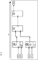
- Fig. 1 shows an example of an image of a graphic representation of a signal processing functionality using a plurality of function modules 2.1, 2.2, 2.3 and 2.4 based on a predetermined format, each with at least one signal input and one signal output for specifying respective functionalities or partial signal processing functionalities.
- this predetermined format is referred to below in the description and in the claims as the second format.
- connection modules 2.5, 2.6, 2.7 and 2.8 which respectively represent the functionality of the physical interfaces coupled to the input side of the signal processing functionality
- connection module 2.9 which represents the functionality of a physical interface coupled to the output side of the signal processing functionality
- the depicted image of a graphical representation of the signal processing functionality thus represents, by way of example, a signal processing functionality that is to be implemented functionally for a predetermined application and is ultimately to be implemented according to the configuration by means of the appropriately provided and / or selected function modules and expediently further modules.
- Such engineering tools for configuring a control device which are set up using and integrating a graphical user interface, the signal processing functionality to be implemented for a particular application, i.e. ultimately the application program to be processed after generation and configuration, functional on a graphical user interface, i.e.
- a graphical user interface i.e.
- To display graphically by means of provided and / or selected function modules and other modules based on a predetermined format and thus expediently also to provide graphical operability thus comprise at least one configuration program which can be executed on a data processing system and is set up on a connection to the data processing system
- Display device to display a graphical user interface, on which a plurality of function blocks based on this specific format and further blocks are provided and can be used for the configuration of the control device by means of the graphical user interface.
- function blocks based on the second format can consequently be used in the configuration of a control device by means of a configuration program which can process the function blocks based on this second format and can be executed on a data processing system and is set up on a data processing system to display a graphical user interface on the connected display device, on which a plurality of function blocks based on this second format are provided and can be used by means of the graphical user interface right up to the configuration of the control device, so that one as exemplified in Fig. 1
- the graphical representation of the signal processing functionality illustrated can be represented on the graphical user interface by means of the suitable engineering tool and can be converted into an executable application program.
- the term “project printout” is also used in the context of the invention.
- Such an image of a graphic representation or such a project printout can e.g. also available as a PDF document.
- Fig. 1 shown image of a graphical representation of a signal processing functionality with a plurality of at least function blocks, which are all based on the second format, in the example shown, additional input modules, as well as output modules based on the same format, are expediently coupled in a graphical representation
- the route according to the invention is more preferred below, including Embodiments described within the scope of the invention, ie for converting this image of a graphical representation of the signal processing functionality into a graphical representation of the signal processing functionality on a graphical user interface, but with a plurality of at least function modules that are based on another, predetermined format and can accordingly be used in the configuration of a control device by means of a configuration program which can process the function blocks based on this other, predetermined format.
- this other predetermined format is referred to below in the description and in the claims as the first format.
- the other, predetermined, i.e. Function blocks based on the first format and expediently further blocks can consequently be used in the configuration of a control device by means of a configuration program which can be executed on a data processing system and is set up to display this graphical user interface on a display device connected to a data processing system, on which a plurality are provided by function blocks based on this first format and can be used by means of the graphical user interface for generating an executable application program and the configuration of the control device based thereon.
- This graphical user interface provides a plurality of at least function modules, which are based on the first format and each have at least one input for input signals and one output for output signals for specifying respective signal processing sub-functionalities, and enables the function modules to be selected in each case by means of the graphical user interface in order to to use them for the configuration of a hardware component, for example.
- the preferably safe modules and their functionalities are integrated, for example, in the graphical programming interface of the configuration software in order to implement a specific safety function in the creation of a safety logic, ie in the configuration of a control device.
- the function blocks provided and / or selected by means of the graphical user interface and expediently also further blocks each have, for example, a correspondence in the hardware component on which a control logic is present, which includes the corresponding function blocks.
- the function blocks provided and also further blocks can be combined, for example, in a library or a respective memory area of one or more libraries.
- the corresponding function block can be selected, for example, using the graphical user interface, or it can also be provided that the activation takes place after the selection.
- a selected or activated function block can be used by means of the graphical user interface for parameterization and / or linkage with other function blocks, so that the behavior of the function block (s) in the hardware component can be influenced.
- the function blocks each provide a specific, independent function that acts on input signals in order to generate output signals, the function blocks being expediently executable or activatable independently.
- a graphic representation of a signal processing functionality with at least a plurality of function modules based on the second format into a graphic representation of a signal processing functionality using a plurality of function modules based on the first format, each with at least one signal input and one signal output for specifying respective signal processing sub-functionalities, ie
- an image of a graphical representation of a signal processing functionality with at least a plurality of function modules based on the second format is first provided, for example in Fig.
- FIG. 1 Exemplary image shown using function blocks 2.1, 2.2, 2.3 and 2.4, each with at least one signal input and one signal output for specifying respective functionalities or partial signal processing functionalities.
- This image expediently contains further modules based on the second format, such as, for example, in Fig. 1 Connection modules 2.5, 2.6, 2.7, 2.8 and 2.9 shown.
- For the Functional interconnection also contains corresponding, graphically represented signal paths or links between the blocks.
- the function block 2.1 represents, as the signal processing partial functionality, an emergency stop or emergency stop functionality, for example, which can be assigned a parameterization property, for example a threshold value to be exceeded.
- the connection modules connected graphically according to the second format and connected on the input side are marked with 2.5 and 2.6 and indicate that according to Fig. 1 accordingly, an input signal I0 is to be applied to the upper input and an input signal I1 to the lower input of the function block 2.1.
- the output of function block 2.1 is according to Fig. 1 For example, placed on a first input of the function block 2.3, the function block 2.3 in the present example representing an AND logic functionality.
- the output of function module 2.2 is connected to the second input of function module 2.3, which in turn provides two inputs to which a signal I2 assigned with reference number 2.7 is to be applied and a signal I3 assigned with reference number 2.8.
- the output of the function block 2.3 is in turn connected to the input of a subsequent function block 2.4, which in the present example provides the partial signal processing functionality of a special transistor circuit.
- An output of the function block 2.4 is then connected, for example, to the connection block 2.9, to which, in the present case, an output signal O0 can be provided at the end of the graphically represented partial signal processing functionality and consequently can be used further.
- such an image of a graphic representation or a project printout as mentioned above which is provided, for example, printed out on paper or as a PDF file or also as an image file, such as, for example, as a JPG file, is initially optically for a subsequent image recognition scanned, ie optically scanned, along at least two different scanning directions, in particular in order to minimize scanning errors as far as possible for safety reasons and / or to appropriately detect possible sources of errors as early as possible.
- the applications for which generic signal processing functionalities are to be implemented are not only non-safe (non-safe) applications, but frequently and primarily also safe (safe) applications, ie applications that are safe in their function have to.
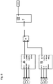
- Fig. 2 provides the optical scanning of the according to greatly simplified Fig. 1 provided image along a first scanning direction 3A, for example from the signal input side to the signal output side, the illustration in FIG Fig. 1 Signal paths shown to illustrate the scanning direction Fig. 3 have been marked with an arrow corresponding to the scanning direction.
- Fig. 4 represents a further scanning 3B, but in one for Fig. 2 shown scanning direction 3A other, second scanning direction 3B, for example from the signal output side towards the signal input side.
- the signal paths are in accordance Fig. 1 for illustration at Fig. 4 likewise with an arrow along this other scanning direction there.
- the Figures 3 and 5 show in a highly simplified view one for processing a with the scanning along the first scanning direction ( Fig. 2 ) obtained image 2A following necessary process section or one for processing a scan with along the second scanning direction ( Fig. 4 ) obtained image 2B subsequent, necessary process section.
- the images 2A and 2B obtained with the scanning processes can also be imported directly into a data processing location during the scanning or after the scanning for further processing, expediently into that on which the configuration program with which the modules based on the first format are used during configuration a control device can be used, can be executed and is set up to display the graphical user interface on the display device connected to the data processing system.
- the further processing then includes the following process section in accordance with Fig. 3 performing image recognition 4A of the image 2A obtained by the first scanning process, generating 5A based thereon of a first data record DS1 representing signal processing partial functionalities and generating 6A a first intermediate code ZC1 based on the generated first data record DS1 and in a corresponding manner Fig. 5 performing image recognition 4B of the image 2B obtained by the second scanning process, generating 5B based thereon a second data record DS2 representing signal processing partial functionalities, and generating 6B a second intermediate code ZC2 based on the generated second data record DS2.
- known graphical representations or symbols of function blocks known in the second format and whose signal processing functionalities are known to the configuration program and expediently also further blocks are stored in a library or a memory area S.2 of such a library.
- the one or more such libraries can thus be on the data processing location on which the configuration program can be executed or on another external device and / or are available as program files, for example on a storage medium with a software program stored thereon, which is on the data processing system is executable and can be set up to interact with the configuration program executable and set up on the data processing system for carrying out the method, at least based on the images 2A, 2B obtained by the scanning processes.
- Appropriate access to these or to several such libraries is therefore expediently given for the execution of the method section in each case for its implementation, in particular computer or software-based implementation.
- the configuration program itself or another suitably set-up program for example expediently runs on the aforementioned storage medium stored software program, within the scope of each image recognition 4A, 4B, by means of a comparison with the function blocks known from the configuration program and in the signal processing functionalities known to the configuration program and stored in the known, stored in the library S.2, functional blocks and expediently also further blocks. If such a known graphical representation stored in library S.2 is recognized, the signal processing partial functionality known in accordance with this graphical representation is used for the generation 5A, 5B of the respective data record DS1, DS2 based on the image recognition.
- the signal processing partial functionalities can consequently also be expediently stored in the library or can be determined, for example, in cooperation with the configuration program and therefore do not have to originate directly from the library which is used by the two in the Figures 3 and 5 dashed arrows, indicated with 5A and 5B respectively. It is only essential in particular that the known graphic representations of the function blocks based on the second format and expediently also further blocks stored in the library S.2 are clearly in their respective signal processing partial functionality. Consequently, when a respective data record DS1, DS2 is identified and generated thereon, in a preferred development, the links between the modules based on the second format contained in the images 2A, 2B obtained by the scanning processes are also evaluated.
- a first or second intermediate code ZC1, ZC2, in particular special machine code, is then generated on the basis of the first data record DS1 and second data record DS2 generated in this way.
- the information contained in the scanned images 2A and 2B is first evaluated by the above-described detection and subsequent data record generation and then, i.e. Before a comparison, again converting these generated data records into a respective intermediate code and consequently only comparing these intermediate codes ZC1 and ZC2 with one another, offers as a major advantage that such a comparison is already made per se on the program level and not only on the optical level Graphic recognition and / or optically identified component including the graphically represented (partial) functionality. In other words, two codes for an identity comparison that are basically executable for a processor must already be available.
- step of comparing (cf. Fig. 6 If reference number 7) leads to the result that there is no identity of the first intermediate code ZC1 and the second intermediate code ZC2, an error message is expediently output and the method is ended. It can then be started again, for example by restarting the image twice again.
- the configuration program is set up, in each case at least one function module 1.1., 1.2, 1.3 based on the first format for at least one known signal processing partial functionality used in the generation select automatically, as for Fig.
- the function blocks based on the first format and expediently also further blocks are in this case stored, for example, in a library or in a memory area S.1 of such a library. Consequently, in the step of selecting 8, the links between components based on the second format contained in the images 2A, 2B obtained by the scanning processes are preferably also evaluated in order to ensure unambiguousness in the selection.
- the configuration program thus constructs based on the known signal processing sub-functionalities used, i.e.
- signal processing sub-functionalities using functional modules based on the first format and expediently also additional modules based on the first format, recognized the signal processing functionality as a whole. If all of the function blocks contained in Figures 2A and 2B and based on the second format and expediently also other blocks, in particular connection blocks, have been clearly recognized, the result is the same signal processing functionality in terms of functionality that was generated on the graphical user interface B, but with the first Format instead of with building blocks based on the second format.
- the signal processing functionality is graphically represented on the graphical user interface B using the selected function modules 1.1., 1.2, 1.3 based on the first format, their respective signal inputs and signal outputs are also automatically linked to one another in accordance with the respective known signal processing sub-functionalities used in the generation .
- At least the information as to which signal processing partial functionalities have been recognized and expediently, whether all have been recognized are thus available to the configuration program or must be provided to the configuration program by the program which carries out the recognition.
- at least one of the images 2A obtained with the scanning processes is also indicated and 2B and / or at least the function blocks contained therein, based on the second format and expediently also further blocks, are made available to the configuration program for the configuration program for the step of generating or reconstructing, ie in particular by the program which carries out the recognition.
- a recognized function block based on the second format can of course also be replaced by a plurality of selected function blocks based on the first format in the signal processing functionality graphically represented by the configuration program.
- the invention also provides that if not all function blocks or further blocks based on the second format have been recognized in the image recognition by comparison with the known graphic representations stored in library S.2, such a function block or further block based on the second format, not recognized, in the Graphic representation of the signal processing functionality by the configuration program, by means of which recognized function blocks based on the second format are replaced by selected function blocks based on the first format, is also displayed.
- Fig. 8 outlined.
- function block 2.4 has not been recognized and continues to be shown in the graphical representation of the Signal processing functionality included. This can also be conveniently displayed to the user, for example graphically highlighted, as in Fig. 8 exemplary with the "?” clarifies.
- the method and thus also the configuration program are particularly preferably set up such that each function block or non-recognized function block based on the second format is subsequently manipulated by means of the graphical user interface, in particular by at least one selected by a user the first format-based function block or other block can be replaced.
- the signal processing functionality finally generated using the configuration program and displayed on the graphical user interface, and therefore also the plurality of function modules used for this, based on the first format, each with at least one signal input and one signal output can consequently also be used for the corresponding configuration of the control device.
- the signal processing functionality finally generated by means of the configuration program consequently also represents the application program to be created after such and then to be processed after configuration.
- an executable application program can consequently be generated and used for the configuration of the control device.
- the signal processing functionality graphically represented using the function modules based on the first format and possibly further modules is again subjected to a plausibility check using the configuration program. If the plausibility check also leads to a positive result, the configuration of the control device in the case of a safe (safe) application can consequently also be regarded as safe.
Landscapes
- Engineering & Computer Science (AREA)
- Physics & Mathematics (AREA)
- General Physics & Mathematics (AREA)
- Automation & Control Theory (AREA)
- Software Systems (AREA)
- General Engineering & Computer Science (AREA)
- Theoretical Computer Science (AREA)
- Stored Programmes (AREA)
- Processing Or Creating Images (AREA)
- Programmable Controllers (AREA)
Applications Claiming Priority (1)
| Application Number | Priority Date | Filing Date | Title |
|---|---|---|---|
| BE20185849A BE1026823B1 (de) | 2018-12-03 | 2018-12-03 | Verfahren zum Erzeugen einer grafischen Darstellung einer Signalverarbeitungsfunktionalität |
Publications (2)
| Publication Number | Publication Date |
|---|---|
| EP3663875A1 true EP3663875A1 (fr) | 2020-06-10 |
| EP3663875B1 EP3663875B1 (fr) | 2021-04-28 |
Family
ID=64899144
Family Applications (1)
| Application Number | Title | Priority Date | Filing Date |
|---|---|---|---|
| EP19211123.5A Active EP3663875B1 (fr) | 2018-12-03 | 2019-11-25 | Procédé de génération d'une représentation graphique d'une fonctionnalité de traitement du signal |
Country Status (2)
| Country | Link |
|---|---|
| EP (1) | EP3663875B1 (fr) |
| BE (1) | BE1026823B1 (fr) |
Citations (2)
| Publication number | Priority date | Publication date | Assignee | Title |
|---|---|---|---|---|
| US20140358817A1 (en) * | 2011-12-23 | 2014-12-04 | Siemens Aktiengesellschaft | Automated project design of a control technology for a technical system |
| WO2018122660A1 (fr) * | 2016-12-28 | 2018-07-05 | Abb Schweiz Ag | Procédé et système de migration de logique de commande dans un système de commande distribué |
-
2018
- 2018-12-03 BE BE20185849A patent/BE1026823B1/de not_active IP Right Cessation
-
2019
- 2019-11-25 EP EP19211123.5A patent/EP3663875B1/fr active Active
Patent Citations (2)
| Publication number | Priority date | Publication date | Assignee | Title |
|---|---|---|---|---|
| US20140358817A1 (en) * | 2011-12-23 | 2014-12-04 | Siemens Aktiengesellschaft | Automated project design of a control technology for a technical system |
| WO2018122660A1 (fr) * | 2016-12-28 | 2018-07-05 | Abb Schweiz Ag | Procédé et système de migration de logique de commande dans un système de commande distribué |
Also Published As
| Publication number | Publication date |
|---|---|
| BE1026823A1 (de) | 2020-06-26 |
| EP3663875B1 (fr) | 2021-04-28 |
| BE1026823B1 (de) | 2020-07-07 |
Similar Documents
| Publication | Publication Date | Title |
|---|---|---|
| EP3667568B1 (fr) | Configuration d'un système de commande pour un véhicule automobile au moins partiellement autonome | |
| DE102004055971B4 (de) | Verfahren und Vorrichtung zur sicheren Parametierung gemäß IEC 61508 SIL 1 bis 3 oder EN 954-1 Kategorie 1 bis 4 | |
| DE102009011679A1 (de) | Verfahren und Vorrichtung zum Erstellen eines Anwenderprogrammes für eine Sicherheitssteuerung | |
| DE10243781A1 (de) | Elektronische Vorrichtung für ein Bussystem | |
| DE112013006769T5 (de) | Erzeugungsprogramm für Ablaufprogramm-Komponenten und Vorrichtung zur Erzeugung von Ablaufprogramm-Komponenten | |
| EP3709166A1 (fr) | Procédé et système de manipulation sécurisée de signal pour l'essai des fonctionnalités de sécurité intégrées | |
| EP2330469B1 (fr) | Procédé et environnement de développement destinés à produire un programme de commande complet exécutable | |
| DE102016011020A1 (de) | Kontaktplan-Überwachungsvorrichtung mit der Fähigkeit, zusätzlich eine Betriebssituation einer CNC in einem Kommentar anzuzeigen | |
| EP3217236A1 (fr) | Procédé et système de génération d'un programme de commande sous forme d'une application mobile exécutable sur un appareil mobile | |
| WO2005076129A1 (fr) | Procede pour configurer un programme informatique | |
| EP3663875B1 (fr) | Procédé de génération d'une représentation graphique d'une fonctionnalité de traitement du signal | |
| EP3268822A1 (fr) | Appareil d'établissement de projet et procédé pour configurer et/ou paramétrer des composants d'automatisation d'un système d'automatisation | |
| DE102018130729B3 (de) | Verfahren zum Erzeugen einer grafischen Darstellung einer Signalverarbeitungsfunktionalität | |
| EP1383061A2 (fr) | Procédé et configurateur pour l'établissement d'un concept d'installation à partir d'un certain nombre de composants d'installation | |
| DE102021208759A1 (de) | Verfahren zum Trainieren eines Algorithmus des maschinellen Lernens zum Erzeugen von Testspezifikationen zum Testen eines auf Software basierenden Systems | |
| EP3629141B1 (fr) | Procédé et dispositif de contrôle d'une valeur paramétrique de configuration | |
| DE102017214610B4 (de) | Verfahren zum Überprüfen von zumindest einer Fahrzeugfunktion sowie Prüfvorrichtung | |
| EP4689814A1 (fr) | Procédé de génération d'un programme de commande pour un système d'automatisation, et environnement de développement | |
| WO2019228910A1 (fr) | Commande programmable à mémoire et procédé de fonctionnement d'une commande programmable à mémoire et produit programme informatique | |
| EP3098748B1 (fr) | Procede de conversion d'au moins un premier fichier de configuration de securite | |
| DE102015115797B4 (de) | Verfahren zum Erzeugen von elektronischen Dokumenten | |
| EP3757688B1 (fr) | Procédé de configuration d'une machine industrielle | |
| EP4123396A1 (fr) | Technique destinée à la réalisation d'une visualisation pour une installation technique d'automatisation dotée d'une commande à mémoire programmable | |
| EP3933593A1 (fr) | Procédé et programme informatique destinés aux essais d'un système technique | |
| EP2930624A1 (fr) | Procédé et dispositif de production et de traitement de tests |
Legal Events
| Date | Code | Title | Description |
|---|---|---|---|
| PUAI | Public reference made under article 153(3) epc to a published international application that has entered the european phase |
Free format text: ORIGINAL CODE: 0009012 |
|
| STAA | Information on the status of an ep patent application or granted ep patent |
Free format text: STATUS: REQUEST FOR EXAMINATION WAS MADE |
|
| 17P | Request for examination filed |
Effective date: 20191125 |
|
| AK | Designated contracting states |
Kind code of ref document: A1 Designated state(s): AL AT BE BG CH CY CZ DE DK EE ES FI FR GB GR HR HU IE IS IT LI LT LU LV MC MK MT NL NO PL PT RO RS SE SI SK SM TR |
|
| AX | Request for extension of the european patent |
Extension state: BA ME |
|
| RIC1 | Information provided on ipc code assigned before grant |
Ipc: G05B 19/05 20060101ALI20201130BHEP Ipc: G06F 8/76 20180101ALI20201130BHEP Ipc: G05B 19/042 20060101AFI20201130BHEP |
|
| GRAP | Despatch of communication of intention to grant a patent |
Free format text: ORIGINAL CODE: EPIDOSNIGR1 |
|
| STAA | Information on the status of an ep patent application or granted ep patent |
Free format text: STATUS: GRANT OF PATENT IS INTENDED |
|
| INTG | Intention to grant announced |
Effective date: 20210114 |
|
| GRAS | Grant fee paid |
Free format text: ORIGINAL CODE: EPIDOSNIGR3 |
|
| GRAA | (expected) grant |
Free format text: ORIGINAL CODE: 0009210 |
|
| STAA | Information on the status of an ep patent application or granted ep patent |
Free format text: STATUS: THE PATENT HAS BEEN GRANTED |
|
| AK | Designated contracting states |
Kind code of ref document: B1 Designated state(s): AL AT BE BG CH CY CZ DE DK EE ES FI FR GB GR HR HU IE IS IT LI LT LU LV MC MK MT NL NO PL PT RO RS SE SI SK SM TR |
|
| REG | Reference to a national code |
Ref country code: GB Ref legal event code: FG4D Free format text: NOT ENGLISH |
|
| REG | Reference to a national code |
Ref country code: CH Ref legal event code: EP |
|
| REG | Reference to a national code |
Ref country code: DE Ref legal event code: R096 Ref document number: 502019001319 Country of ref document: DE |
|
| REG | Reference to a national code |
Ref country code: AT Ref legal event code: REF Ref document number: 1387785 Country of ref document: AT Kind code of ref document: T Effective date: 20210515 |
|
| REG | Reference to a national code |
Ref country code: IE Ref legal event code: FG4D Free format text: LANGUAGE OF EP DOCUMENT: GERMAN |
|
| REG | Reference to a national code |
Ref country code: LT Ref legal event code: MG9D |
|
| PG25 | Lapsed in a contracting state [announced via postgrant information from national office to epo] |
Ref country code: NL Free format text: LAPSE BECAUSE OF FAILURE TO SUBMIT A TRANSLATION OF THE DESCRIPTION OR TO PAY THE FEE WITHIN THE PRESCRIBED TIME-LIMIT Effective date: 20210428 Ref country code: BG Free format text: LAPSE BECAUSE OF FAILURE TO SUBMIT A TRANSLATION OF THE DESCRIPTION OR TO PAY THE FEE WITHIN THE PRESCRIBED TIME-LIMIT Effective date: 20210728 Ref country code: LT Free format text: LAPSE BECAUSE OF FAILURE TO SUBMIT A TRANSLATION OF THE DESCRIPTION OR TO PAY THE FEE WITHIN THE PRESCRIBED TIME-LIMIT Effective date: 20210428 Ref country code: HR Free format text: LAPSE BECAUSE OF FAILURE TO SUBMIT A TRANSLATION OF THE DESCRIPTION OR TO PAY THE FEE WITHIN THE PRESCRIBED TIME-LIMIT Effective date: 20210428 Ref country code: FI Free format text: LAPSE BECAUSE OF FAILURE TO SUBMIT A TRANSLATION OF THE DESCRIPTION OR TO PAY THE FEE WITHIN THE PRESCRIBED TIME-LIMIT Effective date: 20210428 |
|
| PG25 | Lapsed in a contracting state [announced via postgrant information from national office to epo] |
Ref country code: PT Free format text: LAPSE BECAUSE OF FAILURE TO SUBMIT A TRANSLATION OF THE DESCRIPTION OR TO PAY THE FEE WITHIN THE PRESCRIBED TIME-LIMIT Effective date: 20210830 Ref country code: RS Free format text: LAPSE BECAUSE OF FAILURE TO SUBMIT A TRANSLATION OF THE DESCRIPTION OR TO PAY THE FEE WITHIN THE PRESCRIBED TIME-LIMIT Effective date: 20210428 Ref country code: SE Free format text: LAPSE BECAUSE OF FAILURE TO SUBMIT A TRANSLATION OF THE DESCRIPTION OR TO PAY THE FEE WITHIN THE PRESCRIBED TIME-LIMIT Effective date: 20210428 Ref country code: NO Free format text: LAPSE BECAUSE OF FAILURE TO SUBMIT A TRANSLATION OF THE DESCRIPTION OR TO PAY THE FEE WITHIN THE PRESCRIBED TIME-LIMIT Effective date: 20210728 Ref country code: LV Free format text: LAPSE BECAUSE OF FAILURE TO SUBMIT A TRANSLATION OF THE DESCRIPTION OR TO PAY THE FEE WITHIN THE PRESCRIBED TIME-LIMIT Effective date: 20210428 Ref country code: PL Free format text: LAPSE BECAUSE OF FAILURE TO SUBMIT A TRANSLATION OF THE DESCRIPTION OR TO PAY THE FEE WITHIN THE PRESCRIBED TIME-LIMIT Effective date: 20210428 Ref country code: IS Free format text: LAPSE BECAUSE OF FAILURE TO SUBMIT A TRANSLATION OF THE DESCRIPTION OR TO PAY THE FEE WITHIN THE PRESCRIBED TIME-LIMIT Effective date: 20210828 Ref country code: GR Free format text: LAPSE BECAUSE OF FAILURE TO SUBMIT A TRANSLATION OF THE DESCRIPTION OR TO PAY THE FEE WITHIN THE PRESCRIBED TIME-LIMIT Effective date: 20210729 |
|
| REG | Reference to a national code |
Ref country code: NL Ref legal event code: MP Effective date: 20210428 |
|
| PG25 | Lapsed in a contracting state [announced via postgrant information from national office to epo] |
Ref country code: SK Free format text: LAPSE BECAUSE OF FAILURE TO SUBMIT A TRANSLATION OF THE DESCRIPTION OR TO PAY THE FEE WITHIN THE PRESCRIBED TIME-LIMIT Effective date: 20210428 Ref country code: EE Free format text: LAPSE BECAUSE OF FAILURE TO SUBMIT A TRANSLATION OF THE DESCRIPTION OR TO PAY THE FEE WITHIN THE PRESCRIBED TIME-LIMIT Effective date: 20210428 Ref country code: ES Free format text: LAPSE BECAUSE OF FAILURE TO SUBMIT A TRANSLATION OF THE DESCRIPTION OR TO PAY THE FEE WITHIN THE PRESCRIBED TIME-LIMIT Effective date: 20210428 Ref country code: CZ Free format text: LAPSE BECAUSE OF FAILURE TO SUBMIT A TRANSLATION OF THE DESCRIPTION OR TO PAY THE FEE WITHIN THE PRESCRIBED TIME-LIMIT Effective date: 20210428 Ref country code: DK Free format text: LAPSE BECAUSE OF FAILURE TO SUBMIT A TRANSLATION OF THE DESCRIPTION OR TO PAY THE FEE WITHIN THE PRESCRIBED TIME-LIMIT Effective date: 20210428 Ref country code: RO Free format text: LAPSE BECAUSE OF FAILURE TO SUBMIT A TRANSLATION OF THE DESCRIPTION OR TO PAY THE FEE WITHIN THE PRESCRIBED TIME-LIMIT Effective date: 20210428 Ref country code: SM Free format text: LAPSE BECAUSE OF FAILURE TO SUBMIT A TRANSLATION OF THE DESCRIPTION OR TO PAY THE FEE WITHIN THE PRESCRIBED TIME-LIMIT Effective date: 20210428 |
|
| REG | Reference to a national code |
Ref country code: DE Ref legal event code: R097 Ref document number: 502019001319 Country of ref document: DE |
|
| PLBE | No opposition filed within time limit |
Free format text: ORIGINAL CODE: 0009261 |
|
| STAA | Information on the status of an ep patent application or granted ep patent |
Free format text: STATUS: NO OPPOSITION FILED WITHIN TIME LIMIT |
|
| 26N | No opposition filed |
Effective date: 20220131 |
|
| PG25 | Lapsed in a contracting state [announced via postgrant information from national office to epo] |
Ref country code: IS Free format text: LAPSE BECAUSE OF FAILURE TO SUBMIT A TRANSLATION OF THE DESCRIPTION OR TO PAY THE FEE WITHIN THE PRESCRIBED TIME-LIMIT Effective date: 20210828 Ref country code: AL Free format text: LAPSE BECAUSE OF FAILURE TO SUBMIT A TRANSLATION OF THE DESCRIPTION OR TO PAY THE FEE WITHIN THE PRESCRIBED TIME-LIMIT Effective date: 20210428 |
|
| PG25 | Lapsed in a contracting state [announced via postgrant information from national office to epo] |
Ref country code: MC Free format text: LAPSE BECAUSE OF FAILURE TO SUBMIT A TRANSLATION OF THE DESCRIPTION OR TO PAY THE FEE WITHIN THE PRESCRIBED TIME-LIMIT Effective date: 20210428 |
|
| PG25 | Lapsed in a contracting state [announced via postgrant information from national office to epo] |
Ref country code: LU Free format text: LAPSE BECAUSE OF NON-PAYMENT OF DUE FEES Effective date: 20211125 Ref country code: BE Free format text: LAPSE BECAUSE OF NON-PAYMENT OF DUE FEES Effective date: 20211130 |
|
| REG | Reference to a national code |
Ref country code: BE Ref legal event code: MM Effective date: 20211130 |
|
| PG25 | Lapsed in a contracting state [announced via postgrant information from national office to epo] |
Ref country code: IE Free format text: LAPSE BECAUSE OF NON-PAYMENT OF DUE FEES Effective date: 20211125 |
|
| PGFP | Annual fee paid to national office [announced via postgrant information from national office to epo] |
Ref country code: IT Payment date: 20221130 Year of fee payment: 4 Ref country code: FR Payment date: 20221122 Year of fee payment: 4 |
|
| P01 | Opt-out of the competence of the unified patent court (upc) registered |
Effective date: 20230424 |
|
| PG25 | Lapsed in a contracting state [announced via postgrant information from national office to epo] |
Ref country code: CY Free format text: LAPSE BECAUSE OF FAILURE TO SUBMIT A TRANSLATION OF THE DESCRIPTION OR TO PAY THE FEE WITHIN THE PRESCRIBED TIME-LIMIT Effective date: 20210428 |
|
| REG | Reference to a national code |
Ref country code: CH Ref legal event code: PL |
|
| PG25 | Lapsed in a contracting state [announced via postgrant information from national office to epo] |
Ref country code: LI Free format text: LAPSE BECAUSE OF NON-PAYMENT OF DUE FEES Effective date: 20221130 Ref country code: HU Free format text: LAPSE BECAUSE OF FAILURE TO SUBMIT A TRANSLATION OF THE DESCRIPTION OR TO PAY THE FEE WITHIN THE PRESCRIBED TIME-LIMIT; INVALID AB INITIO Effective date: 20191125 Ref country code: CH Free format text: LAPSE BECAUSE OF NON-PAYMENT OF DUE FEES Effective date: 20221130 |
|
| PG25 | Lapsed in a contracting state [announced via postgrant information from national office to epo] |
Ref country code: MK Free format text: LAPSE BECAUSE OF FAILURE TO SUBMIT A TRANSLATION OF THE DESCRIPTION OR TO PAY THE FEE WITHIN THE PRESCRIBED TIME-LIMIT Effective date: 20210428 |
|
| GBPC | Gb: european patent ceased through non-payment of renewal fee |
Effective date: 20231125 |
|
| PG25 | Lapsed in a contracting state [announced via postgrant information from national office to epo] |
Ref country code: MT Free format text: LAPSE BECAUSE OF FAILURE TO SUBMIT A TRANSLATION OF THE DESCRIPTION OR TO PAY THE FEE WITHIN THE PRESCRIBED TIME-LIMIT Effective date: 20210428 |
|
| PG25 | Lapsed in a contracting state [announced via postgrant information from national office to epo] |
Ref country code: GB Free format text: LAPSE BECAUSE OF NON-PAYMENT OF DUE FEES Effective date: 20231125 |
|
| PG25 | Lapsed in a contracting state [announced via postgrant information from national office to epo] |
Ref country code: FR Free format text: LAPSE BECAUSE OF NON-PAYMENT OF DUE FEES Effective date: 20231130 |
|
| PG25 | Lapsed in a contracting state [announced via postgrant information from national office to epo] |
Ref country code: GB Free format text: LAPSE BECAUSE OF NON-PAYMENT OF DUE FEES Effective date: 20231125 Ref country code: FR Free format text: LAPSE BECAUSE OF NON-PAYMENT OF DUE FEES Effective date: 20231130 |
|
| PG25 | Lapsed in a contracting state [announced via postgrant information from national office to epo] |
Ref country code: IT Free format text: LAPSE BECAUSE OF NON-PAYMENT OF DUE FEES Effective date: 20231125 |
|
| PG25 | Lapsed in a contracting state [announced via postgrant information from national office to epo] |
Ref country code: IT Free format text: LAPSE BECAUSE OF NON-PAYMENT OF DUE FEES Effective date: 20231125 |
|
| PG25 | Lapsed in a contracting state [announced via postgrant information from national office to epo] |
Ref country code: TR Free format text: LAPSE BECAUSE OF FAILURE TO SUBMIT A TRANSLATION OF THE DESCRIPTION OR TO PAY THE FEE WITHIN THE PRESCRIBED TIME-LIMIT Effective date: 20210428 |
|
| PG25 | Lapsed in a contracting state [announced via postgrant information from national office to epo] |
Ref country code: AT Free format text: LAPSE BECAUSE OF NON-PAYMENT OF DUE FEES Effective date: 20241125 |
|
| REG | Reference to a national code |
Ref country code: AT Ref legal event code: MM01 Ref document number: 1387785 Country of ref document: AT Kind code of ref document: T Effective date: 20241125 |
|
| PGFP | Annual fee paid to national office [announced via postgrant information from national office to epo] |
Ref country code: DE Payment date: 20260127 Year of fee payment: 7 |
|
| PGFP | Annual fee paid to national office [announced via postgrant information from national office to epo] |
Ref country code: AT Payment date: 20260410 Year of fee payment: 5 |