EP3663875B1 - Procédé de génération d'une représentation graphique d'une fonctionnalité de traitement du signal - Google Patents
Procédé de génération d'une représentation graphique d'une fonctionnalité de traitement du signal Download PDFInfo
- Publication number
- EP3663875B1 EP3663875B1 EP19211123.5A EP19211123A EP3663875B1 EP 3663875 B1 EP3663875 B1 EP 3663875B1 EP 19211123 A EP19211123 A EP 19211123A EP 3663875 B1 EP3663875 B1 EP 3663875B1
- Authority
- EP
- European Patent Office
- Prior art keywords
- format
- signal processing
- functional blocks
- functionality
- generating
- Prior art date
- Legal status (The legal status is an assumption and is not a legal conclusion. Google has not performed a legal analysis and makes no representation as to the accuracy of the status listed.)
- Active
Links
Images


Classifications
-
- G—PHYSICS
- G05—CONTROLLING; REGULATING
- G05B—CONTROL OR REGULATING SYSTEMS IN GENERAL; FUNCTIONAL ELEMENTS OF SUCH SYSTEMS; MONITORING OR TESTING ARRANGEMENTS FOR SUCH SYSTEMS OR ELEMENTS
- G05B19/00—Program-control systems
- G05B19/02—Program-control systems electric
- G05B19/04—Program control other than numerical control, i.e. in sequence controllers or logic controllers
- G05B19/05—Programmable logic controllers, e.g. simulating logic interconnections of signals according to ladder diagrams or function charts
- G05B19/056—Programming the PLC
-
- G—PHYSICS
- G05—CONTROLLING; REGULATING
- G05B—CONTROL OR REGULATING SYSTEMS IN GENERAL; FUNCTIONAL ELEMENTS OF SUCH SYSTEMS; MONITORING OR TESTING ARRANGEMENTS FOR SUCH SYSTEMS OR ELEMENTS
- G05B19/00—Program-control systems
- G05B19/02—Program-control systems electric
- G05B19/04—Program control other than numerical control, i.e. in sequence controllers or logic controllers
- G05B19/042—Program control other than numerical control, i.e. in sequence controllers or logic controllers using digital processors
-
- G—PHYSICS
- G06—COMPUTING OR CALCULATING; COUNTING
- G06F—ELECTRIC DIGITAL DATA PROCESSING
- G06F8/00—Arrangements for software engineering
- G06F8/70—Software maintenance or management
- G06F8/76—Adapting program code to run in a different environment; Porting
-
- G—PHYSICS
- G05—CONTROLLING; REGULATING
- G05B—CONTROL OR REGULATING SYSTEMS IN GENERAL; FUNCTIONAL ELEMENTS OF SUCH SYSTEMS; MONITORING OR TESTING ARRANGEMENTS FOR SUCH SYSTEMS OR ELEMENTS
- G05B2219/00—Program-control systems
- G05B2219/10—Plc systems
- G05B2219/13—Plc programming
- G05B2219/13019—Translate program in order to be used on different plc
-
- G—PHYSICS
- G05—CONTROLLING; REGULATING
- G05B—CONTROL OR REGULATING SYSTEMS IN GENERAL; FUNCTIONAL ELEMENTS OF SUCH SYSTEMS; MONITORING OR TESTING ARRANGEMENTS FOR SUCH SYSTEMS OR ELEMENTS
- G05B2219/00—Program-control systems
- G05B2219/10—Plc systems
- G05B2219/13—Plc programming
- G05B2219/13022—Convert source program to intermediate program
-
- G—PHYSICS
- G05—CONTROLLING; REGULATING
- G05B—CONTROL OR REGULATING SYSTEMS IN GENERAL; FUNCTIONAL ELEMENTS OF SUCH SYSTEMS; MONITORING OR TESTING ARRANGEMENTS FOR SUCH SYSTEMS OR ELEMENTS
- G05B2219/00—Program-control systems
- G05B2219/20—Pc systems
- G05B2219/23—Pc programming
- G05B2219/23258—GUI graphical user interface, icon, function bloc editor, labview
Definitions
- automation systems intended for this purpose are programmed or configured for both safe and non-safe applications using computer-aided planning and configuration tools, so-called engineering tools.
- engineering tools generally enable a simpler and clearer generation of an executable application program and subsequent configuration, including associated parameterization, and often also the commissioning of automation systems.
- This is usually done using and integrating a graphical user interface, so that the engineering tools are set up to functionally, i.e. by means of, the signal processing functionality to be implemented for a respective application, i.e. ultimately the executable application program to be generated and processed after configuration, on a graphical user interface to graphically represent provided and / or selected function modules and further modules and expediently also to provide graphical operability.
- the automation systems that can be programmed or configured with such engineering tools consequently include at least one programmable logic controller (PLC), hereinafter referred to as a control device for the sake of simplicity.
- PLC programmable logic controller
- the graphic representation of a signal processing functionality usually also expediently includes further modules, such as connection modules in particular, which represent the respective physical interfaces coupled to the input side and output side of the signal processing functionality, such as electrical screw terminals in their functionality, to which the input signals to be processed by means of the signal processing functionality are applied or the output signals can be provided at the end of the signal processing functionality and consequently further used.
- connection modules such as connection modules in particular, which represent the respective physical interfaces coupled to the input side and output side of the signal processing functionality, such as electrical screw terminals in their functionality, to which the input signals to be processed by means of the signal processing functionality are applied or the output signals can be provided at the end of the signal processing functionality and consequently further used.
- the modules that can be used for programming and configuration are in this case the respective functionalities or partial functionalities, hereinafter also referred to as signal processing partial functionalities, which can also contain control functionalities, for the sake of standardization, as well as specific graphic symbols or representations assigned to one another and stored in one or more libraries or memory areas there, which the engineering tool can access or enables access.
- Such modules can also be newly created and / or changed, e.g. also by linking several modules, and stored anew with correspondingly new or changed functionalities or partial functionalities as well as specific graphic symbols or representations.
- a module for the application program to be created for the control device to be configured is therefore usually nowadays carried out using a graphical user interface.
- the selected module can also be linked with other modules, for example, and / or an assignment with input and / or output signals can be defined by corresponding graphical connection of connection modules to function modules.
- the graphical representation of a signal processing functionality or an application program to be created by means of the graphical user interface can then also be used by means of the graphical user interface for the configuration of the automation system itself, ie at least one control device.
- the function modules thus each provide a specific independent function that evaluate the input signals in order to generate output signals, the function modules usually being able to be selected, executed and / or activated independently by means of the graphical user interface.
- a function module provided and / or selected by means of the graphical user interface can, for example, also correspond to a hardware component on which control logic is present which provides the function module or its partial functionality.
- the function blocks selected or to be used for an application-related configuration thus each form an essential basis for a certain signal processing functionality of the executable application program to be created, including the graphical functional representation of this signal processing functionality or the application program to be processed after configuration, and are also useful when the application program is running can be used for status display and further configuration.
- a signal processing functionality once compiled, is to be converted from one development status to another development status, on the basis of which function modules graphically displayed on a graphical user interface with an engineering tool set up for this purpose and, expediently, further modules can be used for the configuration of a control device by means of the graphical user interface, with only If the graphical representation of the signal processing functionality is available, which needs to be implemented in the graphical representation of the same signal processing functionality using function blocks and other useful components, which can then also be used again for the configuration of the control device, this is usually extremely time-consuming and costly and in usually only manually through appropriate knowledge of the entire, represented by the graphic representation, actual I signal processing functionality to be realized and so of the application program to be processed after configuration and / or attempts by a user by means of try-and-error.
- An engineering tool for configuring an automation system is, for example, from the publication WO 2018/122660 known.
- One object of the invention is therefore to automatically create a graphic representation of a signal processing functionality that is based on graphically displayed function blocks and, if necessary, further blocks which in and of themselves cannot be used for a predetermined engineering tool either for graphic programming or the configuration of automation systems in a graphical representation of the same signal processing functionality, this graphical representation being based on graphically represented function blocks and possibly other blocks that can be used in the aforementioned engineering tool to generate an executable application program and corresponding configuration of automation systems.
- the invention consequently proposes a method for generating a graphical representation of a signal processing functionality on a graphical user interface, specifically using a plurality of function modules based on a first format, each with at least one signal input and one signal output for specifying the respective signal processing sub-functionalities, based on a A plurality of function blocks based on a second format, each with at least one signal input and one signal output for specifying the respective signal processing sub-functionalities, whereby the function blocks based on the first format can be used to generate an executable application program and the configuration of a control device by means of a configuration program, and the configuration program can be executed on a data processing system and is set up for this purpose on a data processing system processing system connected display device the graphic To represent user interface on which a plurality of function modules based on this first format are provided and can be used by means of the graphical user interface for the creation of the application program and configuration of the control device.
- the solution according to the invention provides that, based on a previously provided image of a graphic representation of the signal processing functionality with a plurality of function modules based on the second format, an image recognition, which is optically scanned in along a first scanning direction and along another, second scanning direction of the image obtained by the first scanning process and a generation of a first data set representing signal processing sub-functionalities based thereon as well as image recognition of the image obtained by the second scanning process and based thereon generation of a second data set representing signal processing sub-functionalities.
- a comparison is carried out with known graphic representations or symbols stored in a library of function blocks based on the second format and known to the configuration program in their signal processing sub-functionalities and each time such a known graphic representation stored in the library is recognized, the According to this graphical representation, known signal processing sub-functionality is used for the generation of the respective data record based on the image recognition.
- a first intermediate code is then generated and based on the generated second data set, a second intermediate code is generated, which are then compared with one another.
- the configuration program automatically selects at least one function module based on the first format for at least one known signal processing sub-functionality used in the generation and the Signal processing functionality shown graphically on the graphical user interface, with recognized function blocks based on the second format being replaced by selected function blocks based on the first format.
- an executable application program can consequently also be generated and used for the configuration of the control device.
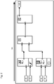
- Fig. 1 shows an example of a graphic representation of a signal processing functionality using a plurality of function modules 2.1, 2.2, 2.3 and 2.4 based on a predetermined format, each with at least one signal input and one signal output for specifying the respective functionalities or signal processing partial functionalities.
- this predetermined format is referred to below in the description and in the claims as the second format.
- connection modules 2.5, 2.6, 2.7 and 2.8 shown which represent the functionality of the respective physical interfaces coupled to the input side of the signal processing functionality, as well as the connection module 2.9, which represents a physical interface coupled to the output side of the signal processing functionality in terms of functionality, nowadays using for This second format equally determined engineering tools for creating an application program and subsequent configuration, including a parameterization associated therewith, and often also the commissioning of automation systems, ie used by at least one control device. That like in Fig.
- the image shown of a graphical representation of the signal processing functionality thus exemplarily represents a signal processing functionality to be implemented for a predetermined application by means of the appropriately provided and / or selected function modules and expediently further modules, which is originally functionally graphically represented on a graphical user interface, i.e. ultimately the application program to be processed after configuration.
- Such engineering tools for the configuration of a control device which are set up using and integrating a graphical user interface, functionally the signal processing functionality to be implemented for a respective application, i.e. ultimately the application program to be processed after generation and configuration, on a graphical user interface, i.e.
- function blocks based on the second format can consequently be used in the configuration of a control device by means of a configuration program that can process the function blocks based on this second format and can be executed on a data processing system and is set up for this purpose on one with the data processing system connected display device to represent a graphical user interface on which a plurality of function modules based on this second format are provided and can be used by means of the graphical user interface up to the configuration of the control device, so that one as exemplified in Fig. 1
- the graphical representation of the signal processing functionality shown can be displayed on the graphical user interface by means of the engineering tool that is therefore suitable for this and can be converted into an executable application program.
- Such a graphical representation of the signal processing functionality reproduced on the graphical user interface is then output as an image, e.g. printed out, by means of the engineering tool, this is also referred to as a so-called project printout within the scope of the invention.
- Such an image of a graphic representation or such a project printout can also be available as a PDF document, for example.
- FIG. 1 The image shown of a graphic representation of a signal processing functionality with a plurality of at least function blocks, all of which are based on the second format, in which case in the example shown, connection blocks based on the same format on the input and output sides are expediently coupled in a graphic representation, the method according to the invention including the preferred is below , described embodiments lying within the scope of the invention, ie to implement this image of a graphical representation of the signal processing functionality in a graphical representation of the signal processing functionality on a graphical user interface with, however, a plurality of at least function blocks that are based on another, predetermined format and can accordingly be used in the configuration of a control device by means of a configuration program that can process the function modules based on this other, predetermined format.
- this other predetermined format is referred to below in the description and in the claims as the first format.
- the function modules based on this other, predetermined, ie the first format and expediently further modules can consequently be used in the configuration of a control device by means of a configuration program which can be executed on a data processing system and is set up to display this on a display device connected to a data processing system to represent graphical user interface on which a plurality of function modules based on this first format are provided and can be used by means of the graphical user interface for the generation of an executable application program and the configuration of the control device based thereon.
- This graphical user interface provides a plurality of at least function modules which are based on the first format and each have at least one input for input signals and one output for output signals for specifying the respective signal processing sub-functionalities, and enables the function modules to be selected using the graphical user interface in order to to use them for the configuration of a hardware component, for example.
- the preferably safe modules and their functionalities are integrated, for example, into the graphic programming interface of the configuration software in order to implement a specific safety function in the creation of a safety logic, ie when a control device is configured.
- the function blocks provided and / or selected by means of the graphical user interface and, expediently, further blocks each have, for example, an equivalent in the hardware component on which a control logic is present, which includes the corresponding function blocks.
- the function blocks provided and also other blocks can be combined, for example, in a library or a respective memory area of one or more libraries.
- the corresponding function block can be selected, for example, using the graphical user interface, or it can also be provided that activation takes place after selection.
- a selected or activated function block can be used by means of the graphical user interface for parameterization and / or linking with other function blocks, so that the behavior of the function block (s) in the hardware component can be influenced.
- the function modules each provide a specific, independent function which act on input signals in order to generate output signals, with the function modules expediently each being able to be executed or activated independently.
- an image of a graphic representation of a signal processing functionality with at least a plurality of function modules based on the second format is first provided, for example the one in Fig.
- the function module 2.1 represents, for example, an emergency stop or emergency stop functionality, which can be assigned a parameterization property, for example a threshold value to be exceeded.
- the connection modules connected on the input side are graphically represented in accordance with the second format and are marked with 2.5 and 2.6 and indicate that according to Fig. 1 accordingly an input signal I0 is to be applied to the upper input and an input signal I1 to the lower input of function block 2.1.
- the output of function block 2.1 is in accordance with Fig. 1 for example applied to a first input of the function block 2.3, the function block 2.3 in the present example representing an AND link functionality.
- the output of function block 2.2 is applied to the second input of function block 2.3, which in turn provides two inputs to which a signal I2 assigned the reference symbol 2.7 and a signal I3 assigned the reference symbol 2.8 are to be applied.
- the output of the function block 2.3 is in turn applied to the input of a subsequent function block 2.4 which, in the present example, provides the signal processing sub-functionality of a special transistor circuit, for example.
- An output of the function module 2.4 is then connected, for example, to the connection module 2.9, at which, in the present case, an output signal O0 can be provided at the end of the graphically represented signal processing sub-functionality and can consequently be used further.
- such an image of a graphic representation or a project printout as mentioned above which is provided, for example, on paper or as a PDF file or also as an image file, such as a JPG file, is initially provided optically for subsequent image recognition scanned in, ie optically scanned, specifically along at least two different scanning directions, in particular in order to minimize scanning errors as far as possible for safety reasons and / or expediently detect possible sources of error as early as possible.
- the applications for which generic signal processing functionalities are to be implemented are not only non-safe applications, but often and primarily also safe applications, i.e. applications that are functionally safe have to.
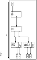
- Fig. 2 now greatly simplifies the optical scanning of the according to Fig. 1 provided image along a first scanning direction 3A, by way of example from the signal input side to the signal output side, in this respect, for illustration, also those in the image according to FIG Fig. 1 signal paths shown to illustrate the scanning direction Fig. 3 have been assigned an arrow corresponding to the scanning direction.
- Fig. 4 shows a further scanning process 3B, but in one for Fig. 2 scanning direction 3A shown in another, second scanning direction 3B, for example from the signal output side in the direction of the signal input side.
- the signal paths are in accordance with Fig. 1 for illustration at Fig. 4 likewise occupied by an arrow along this other scanning direction there.
- the Figures 3 and 5 show in a greatly simplified view a for processing a with the scanning along the first scanning direction ( Fig. 2 ) obtained image 2A subsequent, necessary process section or for processing a with the scanning along the second scanning direction ( Fig. 4 ) obtained image 2B following, necessary process section.
- the images 2A and 2B obtained with the scanning processes can also be imported into a data processing system immediately during scanning or after scanning for further processing, expediently into the one on which the configuration program, with which the modules based on the first format are configured during configuration a control device can be used, can be executed and is set up to display the graphical user interface on the display device connected to the data processing system.
- the further processing then comprises as a respective subsequent method section according to Fig. 3 performing an image recognition 4A of the image 2A obtained by the first scanning process, generating 5A based thereon of a first data set DS1 representing signal processing sub-functionalities and generating 6A a first intermediate code ZC1 based on the generated first data set DS1 and in a corresponding manner according to FIG Fig. 5 performing an image recognition 4B of the image 2B obtained by the second scanning process, generating 5B based thereon of a second data record DS2 representing signal processing sub-functionalities and generating 6B a second intermediate code ZC2 based on the generated second data record DS2.
- known graphic representations or symbols of function modules which are based on the second format and whose signal processing sub-functionalities are known to the configuration program and expediently also further modules are stored in a library or a memory area S.2 of such a library.
- the or more such libraries can thus be present on the data processing system on which the configuration program can be executed or on another external device and / or as program files, e.g. on a storage medium with a software program stored on it, which is stored on the data processing system can be executed and can be set up to interact with the configuration program that can be executed and set up on the data processing system to carry out the method, at least based on the images 2A, 2B obtained through the scanning processes.
- the respectively outlined procedural section is therefore given appropriate access to this or also to several such libraries for its implementation, in particular computer-assisted or software-assisted implementation.
- the configuration program itself or another appropriately set up program, for example, expediently the one on the aforementioned storage medium stored software program, in the context of each image recognition 4A, 4B, a comparison with the known graphic representations stored in the library S.2 of function modules based on the second format and known to the configuration program in their signal processing sub-functionalities, and expediently also other modules. If such a known graphic representation stored in the library S.2 is recognized, the signal processing sub-functionality known corresponding to this graphic representation is used for the generation 5A, 5B of the respective data set DS1, DS2 based on the image recognition.
- the signal processing sub-functionalities can therefore also be appropriately stored in the library or, for example, be determined in conjunction with the configuration program and therefore do not have to come directly from the library, which is entered into by the two Figures 3 and 5 is indicated by dashed arrows marked 5A and 5B, respectively. It is only essential, in particular, that the known graphic representations of function blocks based on the second format and expediently also other blocks stored in the library S.2 are unambiguous in their respective signal processing sub-functionality. Consequently, in a preferred development, the links between modules based on the second format contained in the images 2A, 2B obtained by the scanning processes are also evaluated during the detection and the generation of a respective data record DS1, DS2 based on this.
- a first or second intermediate code ZC1, ZC2, in particular a special machine code, is then generated based on the first data record DS1 and second data record DS2 generated in this way.
- step of comparing leads to the result that there is no identity of the first intermediate code ZC1 and the second intermediate code ZC2, an error message is expediently output and the method is ended. It can then be started again, for example by re-scanning the image twice.
- the configuration program is set up, in each case at least one function module 1.1., 1.2, 1.3 based on the first format for at least one known signal processing sub-functionality used in the generation automatically select, as with Fig. 7 on the user interface B sketched there with the reference numeral 8, and to graphically represent the signal processing functionality on the graphical user interface B, with recognized function blocks 2.1, 2.2, 2.3, 2.4 based on the second format and, expediently, also recognized other ones based on the second format Modules, i.e.
- connection modules 2.5, 2.6, 2.7, 2.8, 2.9 which represent physical interfaces in their function on the input side and output side of the signal processing functionality, through appropriately selected function modules 1.1., 1.2, 1.3 and, appropriately, also based on the first format by accordingly selected further modules based on the first format, that is to say in particular corresponding connection modules 1.5, 1.6, 1.7, 1.8, 1.9, 1.10, 1.11 are replaced.
- the function modules based on the first format and expediently also further modules are in this case, for example, again stored in a library or a memory area S.1 of such a library. Consequently, in the step of selecting 8, the links between modules based on the second format contained in the images 2A, 2B obtained by the scanning processes are preferably also evaluated again in order to ensure uniqueness in the selection.
- the configuration program consequently constructs the signal processing functionality entirely new based on the known signal processing sub-functionalities used, i.e. recognized signal processing sub-functionalities, using function modules based on the first format and expediently also further modules based on the first format. If all of the function blocks based on the second format and expediently also other blocks, i.e. in particular connection blocks, contained in Figures 2A and 2B were clearly identified, the result is the same signal processing functionality generated on the graphical user interface B, but also on the first Format instead of building blocks based on the second format.
- the signal processing functionality is graphically displayed on the graphical user interface B using the selected function blocks 1.1., 1.2, 1.3 based on the first format, their respective signal inputs and outputs are automatically linked to one another in accordance with the respective known signal processing sub-functionalities used during generation .
- At least the information as to which signal processing sub-functionalities have been recognized and, expediently, whether all have been recognized, are therefore available to the configuration program in the result or must be given to it by the program that carries out the recognition.
- the configuration program in the result or must be given to it by the program that carries out the recognition.
- a recognized function module based on the second format can be replaced by a single selected module based on the first format, such as function modules 2.3 and 2.4 (see also Fig. 1 ) through function block 1.3.
- a recognized function module based on the second format can of course also be replaced by several selected function modules based on the first format in the signal processing functionality graphically represented by the configuration program.
- the method and thus also the configuration program for such a case are set up in such a way that each unrecognized function module based on the second format or also further module is subsequently manipulated by means of the graphical user interface, in particular by at least one selected by a user the first format-based function block or other blocks can be replaced.
- the signal processing functionality finally generated using the configuration program and displayed on the graphical user interface and thus also the plurality of function modules based on the first format, each with at least one signal input and one signal output, can consequently also be used for the corresponding configuration of the control device.
- the signal processing functionality finally generated by means of the configuration program consequently also represents the application program to be created after such a program and then to be processed after configuration.
- an executable application program can consequently be generated and used for the configuration of the control device.
- the signal processing functionality graphically represented using the function modules based on the first format and possibly further modules is subjected to a plausibility check again by means of the configuration program. If the plausibility check also leads to a positive result, the configuration of the control device in the case of a safe application can again be viewed as safe.
Landscapes
- Engineering & Computer Science (AREA)
- Physics & Mathematics (AREA)
- General Physics & Mathematics (AREA)
- Automation & Control Theory (AREA)
- Software Systems (AREA)
- General Engineering & Computer Science (AREA)
- Theoretical Computer Science (AREA)
- Stored Programmes (AREA)
- Processing Or Creating Images (AREA)
- Programmable Controllers (AREA)
Claims (9)
- Procédé de génération d'une représentation graphique d'une fonctionnalité de traitement de signaux sur une interface utilisateur graphique (B) à l'aide d'une pluralité de composants fonctionnels (1.1, 1.2, 1.3) basé sur un premier format, chacun avec une entrée de signal et une sortie de signal pour la spécification de fonctionnalités partielles de traitement de signaux respectives, sur la base d'une pluralité de composants fonctionnels (2.1, 2.2, 2.3, 2.4) basés sur un deuxième format, chacun avec une entrée de signal et une sortie de signal pour la spécification de fonctionnalités partielles de traitement de signaux respectives, où les composants fonctionnels basés sur le premier format peuvent être utilisés lors de la configuration d'un dispositif de commande au moyen d'un programme de configuration et le programme de configuration peut être exécuté sur une installation de traitement de données et est conçu pour représenter, sur un dispositif d'affichage relié avec l'installation de traitement de données, cette interface utilisateur graphique (B), sur laquelle une pluralité de composants fonctionnels basés sur ce premier format sont mis à disposition et peuvent être utilisés au moyen de l'interface utilisateur graphique pour la configuration du dispositif de commande, comprenant les étapes consistant en :- la mise à disposition d'une image d'une représentation graphique de la fonctionnalité de traitement de signaux avec une pluralité de composants fonctionnels (2.1, 2.2, 2.3, 2.4) basés sur le deuxième format,- balayage optique (3A, 3B) de cette image, où un premier processus de balayage optique (3A) est effectué le long d'une première direction de balayage et un deuxième processus de balayage optique (3B) est effectué le long d'une deuxième direction de balayage différente de la première direction de balayage,- la réalisation d'une reconnaissance d'image (4A) de l'image (2A) obtenue grâce au premier processus de balayage (3A) et la production (5A), sur cette base, d'un premier ensemble de données (DS1) représentant des premières fonctionnalités partielles de traitement de signaux ainsi que la réalisation d'une reconnaissance d'image (4B) de l'image (2B) obtenue grâce au deuxième processus de balayage (3B) et la production (5B), sur cette base, d'un deuxième ensemble de données (DS2) représentant des deuxièmes fonctionnalités partielles de traitement de signaux, où, à chaque reconnaissance d'image (4A, 4B), une comparaison des composants basés sur le deuxième format et connus du programme de configuration dans leurs fonctionnalités partielles de traitement des signaux, est effectuée avec des représentations graphiques connues enregistrées dans une bibliothèque (S.2) et, à chaque reconnaissance d'une telle représentation graphiques connue enregistrée dans la bibliothèque (S.2), la fonctionnalité partielle de traitement de signaux connue selon cette représentation graphique est utilisée pour la production (5A, 5B), basée sur la reconnaissance d'image, de l'ensemble de données (DS1, DS2) correspondant,- la génération (6A) d'un premier code intermédiaire (ZC1) sur la base du premier ensemble de données (DS1) produit et la génération (6B) d'un deuxième code intermédiaire (ZC2) sur la base du deuxième ensemble de données (DS2) produit,- la comparaison (7) du premier code intermédiaire (ZC1) avec le deuxième code intermédiaire (ZC2) et, tant que l'étape de comparaison arrive au résultat d'une identité du premier code intermédiaire et du deuxième code intermédiaire, la sélection automatique (8) par le programme de configuration de respectivement au moins un composant fonctionnel basé sur le premier format pour respectivement au moins une fonctionnalité partielle de traitement de signaux connue utilisée lors de la production et représentation graphique de la fonctionnalité de traitement de signaux sur l'interface utilisateur graphique (B), où les composants fonctionnels reconnus basés sur le deuxième format sont remplacés par des composants fonctionnels sélectionnés basés sur le premier format.
- Procédé selon la revendication 1, dans lequel, lors de la représentation graphique de la fonctionnalité de traitement de signaux à l'aide des composants fonctionnels (1.1, 1.2, 1.3) basés sur le premier format sélectionnés, des entrées de signaux et des sorties de signaux sont automatiquement combinées entre elles lors de la production de fonctionnalités partielles de traitement de signaux connues respectives.
- Procédé selon la revendication 1 ou 2, dans lequel, dans le cas où tous les composants fonctionnels basés sur le deuxième format sont reconnus lors de la reconnaissance d'image à l'aide de la comparaison avec les représentations graphiques connues enregistrées dans la bibliothèque (S1, S2), un tel composant fonctionnel, basé sur le deuxième format, non reconnu, continue d'être représenté, lors de la représentation graphique de la fonctionnalité partielle de traitement de signaux, dans laquelle les composants fonctionnels reconnus basés sur le deuxième format sont remplacés par des composants fonctionnels sélectionnés basés sur le premier format.
- Procédé selon la revendication 3, dans lequel chaque composant fonctionnel non reconnu basé sur le deuxième format peut être manipulé ultérieurement au moyen de l'interface utilisateur graphique, plus particulièrement peut être remplacé par au moins un composant fonctionnel, basé sur le premier format, sélectionné par un utilisateur.
- Procédé selon l'une des revendications précédentes, dans lequel un composant fonctionnel reconnu basé sur le deuxième format peut également être remplacé par plusieurs composants fonctionnels sélectionnés basés sur le premier format et/ou plusieurs composants fonctionnels reconnus basés sur le deuxième format peuvent également être remplacés par un seul composant fonctionnel sélectionné basé sur le premier format.
- Procédé selon l'une des revendications précédentes, dans lequel la fonctionnalité de traitement de signaux représentée graphiquement à l'aide des composants fonctionnels basés sur le premier format est soumise à un contrôle de plausibilité au moyen du programme de configuration.
- Procédé selon l'une des revendications précédentes, dans lequel l'image comprend également des composants de raccordement basés sur le deuxième format, qui représentent respectivement des interfaces physiques sur les côtés d'entrée et de sortie de la fonctionnalité de traitement de signaux dans leur fonction et ceux-ci sont analysés en fonction des composants fonctionnels basés sur le deuxième format lors de la reconnaissance d'image (4A, 4B), de la production (5A, 5B), basée sur celle-ci, de l'ensemble de données (DS1, DS2) respectif et de la sélection automatique (8) et remplacés par des composants de raccordement basés sur le premier format sélectionnés.
- Procédé selon l'une des revendications précédentes, dans lequel les combinaisons contenues dans les images (2A, 2B), obtenues à l'aide des processus de balayage, entre les composants fonctionnels basés sur le deuxième format sont analysées lors de la reconnaissance d'image (4A, 4B), de la production (5A, 5B) basée sur celle-ci d'un ensemble de données (DS1, DS2) respectif et de la sélection automatique (8) .
- Support de stockage avec un programme logiciel enregistré sur celui-ci, qui est exécutable sur l'installation de traitement de données et peut être mis en œuvre pour l'exécution du procédé selon l'une des revendications précédentes en interaction avec un programme de configuration qui peut exécuté et configuré sur l'installation de traitement de signaux au moins sur la base des images (2A, 2B) obtenues à l'aide des processus de balayage.
Applications Claiming Priority (1)
| Application Number | Priority Date | Filing Date | Title |
|---|---|---|---|
| BE20185849A BE1026823B1 (de) | 2018-12-03 | 2018-12-03 | Verfahren zum Erzeugen einer grafischen Darstellung einer Signalverarbeitungsfunktionalität |
Publications (2)
| Publication Number | Publication Date |
|---|---|
| EP3663875A1 EP3663875A1 (fr) | 2020-06-10 |
| EP3663875B1 true EP3663875B1 (fr) | 2021-04-28 |
Family
ID=64899144
Family Applications (1)
| Application Number | Title | Priority Date | Filing Date |
|---|---|---|---|
| EP19211123.5A Active EP3663875B1 (fr) | 2018-12-03 | 2019-11-25 | Procédé de génération d'une représentation graphique d'une fonctionnalité de traitement du signal |
Country Status (2)
| Country | Link |
|---|---|
| EP (1) | EP3663875B1 (fr) |
| BE (1) | BE1026823B1 (fr) |
Family Cites Families (2)
| Publication number | Priority date | Publication date | Assignee | Title |
|---|---|---|---|---|
| KR101617565B1 (ko) * | 2011-12-23 | 2016-05-02 | 지멘스 악티엔게젤샤프트 | 기술적 시스템의 제어 기술의 자동화된 프로젝트 설계 |
| WO2018122660A1 (fr) * | 2016-12-28 | 2018-07-05 | Abb Schweiz Ag | Procédé et système de migration de logique de commande dans un système de commande distribué |
-
2018
- 2018-12-03 BE BE20185849A patent/BE1026823B1/de not_active IP Right Cessation
-
2019
- 2019-11-25 EP EP19211123.5A patent/EP3663875B1/fr active Active
Non-Patent Citations (1)
| Title |
|---|
| None * |
Also Published As
| Publication number | Publication date |
|---|---|
| EP3663875A1 (fr) | 2020-06-10 |
| BE1026823A1 (de) | 2020-06-26 |
| BE1026823B1 (de) | 2020-07-07 |
Similar Documents
| Publication | Publication Date | Title |
|---|---|---|
| EP2399174B1 (fr) | Procédé et dispositif pour réaliser un programme d'application pour une commande de sécurité | |
| EP1401171B1 (fr) | Dispositif électronique pour un système bus | |
| EP2012201B1 (fr) | Procédé destiné à la programmation d'une commande de sécurité | |
| EP3667568B1 (fr) | Configuration d'un système de commande pour un véhicule automobile au moins partiellement autonome | |
| DE112013006769T5 (de) | Erzeugungsprogramm für Ablaufprogramm-Komponenten und Vorrichtung zur Erzeugung von Ablaufprogramm-Komponenten | |
| DE102016011020A1 (de) | Kontaktplan-Überwachungsvorrichtung mit der Fähigkeit, zusätzlich eine Betriebssituation einer CNC in einem Kommentar anzuzeigen | |
| EP2098928A1 (fr) | Procédé et dispositif adaptés à la programmation et/ou la configuration d'un contrôleur de sécurité | |
| DE102014016180B4 (de) | Verfahren und Einrichtung zur Verwaltung und Konfiguration von Feldgeräten einer Automatisierungsanlage | |
| WO2017182345A1 (fr) | Dispositif et procédé pour adapter une commande numérique à une machine à commander | |
| EP3663875B1 (fr) | Procédé de génération d'une représentation graphique d'une fonctionnalité de traitement du signal | |
| EP3588271A1 (fr) | Procédé et dispositif de configuration d'un composant matériel | |
| EP3268822A1 (fr) | Appareil d'établissement de projet et procédé pour configurer et/ou paramétrer des composants d'automatisation d'un système d'automatisation | |
| EP1365297B1 (fr) | Système et procédé pour adapter des blocs fonctionnels d'application spécifique d'un dispositif d'automation | |
| EP4432034B1 (fr) | Procédé et système de détection d'une configuration d'un contrôleur de sécurité modulaire | |
| DE102018130729B3 (de) | Verfahren zum Erzeugen einer grafischen Darstellung einer Signalverarbeitungsfunktionalität | |
| EP3575898B1 (fr) | Contrôleur programmable à logique et systeme d'operation pour contrôleur programmable et programme informatique | |
| EP3757688B1 (fr) | Procédé de configuration d'une machine industrielle | |
| EP2283426B1 (fr) | Procédé et dispositif permettant de corriger des informations transmises sous forme numérique | |
| EP3098748B1 (fr) | Procede de conversion d'au moins un premier fichier de configuration de securite | |
| EP1886198B1 (fr) | Appareil de parametrage et procede de parametrage d'appareils electriques | |
| EP4123396A1 (fr) | Technique destinée à la réalisation d'une visualisation pour une installation technique d'automatisation dotée d'une commande à mémoire programmable | |
| EP3933593A1 (fr) | Procédé et programme informatique destinés aux essais d'un système technique | |
| EP1477905B1 (fr) | Procédé de conception et procédé de diagnostic pour un système d'automatisation | |
| EP3430771B1 (fr) | Masquage de l'influence de commandes de bus de terrain non prises en charge | |
| DE10316288A1 (de) | Vorrichtung und Verfahren zur Datenübertragung |
Legal Events
| Date | Code | Title | Description |
|---|---|---|---|
| PUAI | Public reference made under article 153(3) epc to a published international application that has entered the european phase |
Free format text: ORIGINAL CODE: 0009012 |
|
| STAA | Information on the status of an ep patent application or granted ep patent |
Free format text: STATUS: REQUEST FOR EXAMINATION WAS MADE |
|
| 17P | Request for examination filed |
Effective date: 20191125 |
|
| AK | Designated contracting states |
Kind code of ref document: A1 Designated state(s): AL AT BE BG CH CY CZ DE DK EE ES FI FR GB GR HR HU IE IS IT LI LT LU LV MC MK MT NL NO PL PT RO RS SE SI SK SM TR |
|
| AX | Request for extension of the european patent |
Extension state: BA ME |
|
| RIC1 | Information provided on ipc code assigned before grant |
Ipc: G05B 19/05 20060101ALI20201130BHEP Ipc: G06F 8/76 20180101ALI20201130BHEP Ipc: G05B 19/042 20060101AFI20201130BHEP |
|
| GRAP | Despatch of communication of intention to grant a patent |
Free format text: ORIGINAL CODE: EPIDOSNIGR1 |
|
| STAA | Information on the status of an ep patent application or granted ep patent |
Free format text: STATUS: GRANT OF PATENT IS INTENDED |
|
| INTG | Intention to grant announced |
Effective date: 20210114 |
|
| GRAS | Grant fee paid |
Free format text: ORIGINAL CODE: EPIDOSNIGR3 |
|
| GRAA | (expected) grant |
Free format text: ORIGINAL CODE: 0009210 |
|
| STAA | Information on the status of an ep patent application or granted ep patent |
Free format text: STATUS: THE PATENT HAS BEEN GRANTED |
|
| AK | Designated contracting states |
Kind code of ref document: B1 Designated state(s): AL AT BE BG CH CY CZ DE DK EE ES FI FR GB GR HR HU IE IS IT LI LT LU LV MC MK MT NL NO PL PT RO RS SE SI SK SM TR |
|
| REG | Reference to a national code |
Ref country code: GB Ref legal event code: FG4D Free format text: NOT ENGLISH |
|
| REG | Reference to a national code |
Ref country code: CH Ref legal event code: EP |
|
| REG | Reference to a national code |
Ref country code: DE Ref legal event code: R096 Ref document number: 502019001319 Country of ref document: DE |
|
| REG | Reference to a national code |
Ref country code: AT Ref legal event code: REF Ref document number: 1387785 Country of ref document: AT Kind code of ref document: T Effective date: 20210515 |
|
| REG | Reference to a national code |
Ref country code: IE Ref legal event code: FG4D Free format text: LANGUAGE OF EP DOCUMENT: GERMAN |
|
| REG | Reference to a national code |
Ref country code: LT Ref legal event code: MG9D |
|
| PG25 | Lapsed in a contracting state [announced via postgrant information from national office to epo] |
Ref country code: NL Free format text: LAPSE BECAUSE OF FAILURE TO SUBMIT A TRANSLATION OF THE DESCRIPTION OR TO PAY THE FEE WITHIN THE PRESCRIBED TIME-LIMIT Effective date: 20210428 Ref country code: BG Free format text: LAPSE BECAUSE OF FAILURE TO SUBMIT A TRANSLATION OF THE DESCRIPTION OR TO PAY THE FEE WITHIN THE PRESCRIBED TIME-LIMIT Effective date: 20210728 Ref country code: LT Free format text: LAPSE BECAUSE OF FAILURE TO SUBMIT A TRANSLATION OF THE DESCRIPTION OR TO PAY THE FEE WITHIN THE PRESCRIBED TIME-LIMIT Effective date: 20210428 Ref country code: HR Free format text: LAPSE BECAUSE OF FAILURE TO SUBMIT A TRANSLATION OF THE DESCRIPTION OR TO PAY THE FEE WITHIN THE PRESCRIBED TIME-LIMIT Effective date: 20210428 Ref country code: FI Free format text: LAPSE BECAUSE OF FAILURE TO SUBMIT A TRANSLATION OF THE DESCRIPTION OR TO PAY THE FEE WITHIN THE PRESCRIBED TIME-LIMIT Effective date: 20210428 |
|
| PG25 | Lapsed in a contracting state [announced via postgrant information from national office to epo] |
Ref country code: PT Free format text: LAPSE BECAUSE OF FAILURE TO SUBMIT A TRANSLATION OF THE DESCRIPTION OR TO PAY THE FEE WITHIN THE PRESCRIBED TIME-LIMIT Effective date: 20210830 Ref country code: RS Free format text: LAPSE BECAUSE OF FAILURE TO SUBMIT A TRANSLATION OF THE DESCRIPTION OR TO PAY THE FEE WITHIN THE PRESCRIBED TIME-LIMIT Effective date: 20210428 Ref country code: SE Free format text: LAPSE BECAUSE OF FAILURE TO SUBMIT A TRANSLATION OF THE DESCRIPTION OR TO PAY THE FEE WITHIN THE PRESCRIBED TIME-LIMIT Effective date: 20210428 Ref country code: NO Free format text: LAPSE BECAUSE OF FAILURE TO SUBMIT A TRANSLATION OF THE DESCRIPTION OR TO PAY THE FEE WITHIN THE PRESCRIBED TIME-LIMIT Effective date: 20210728 Ref country code: LV Free format text: LAPSE BECAUSE OF FAILURE TO SUBMIT A TRANSLATION OF THE DESCRIPTION OR TO PAY THE FEE WITHIN THE PRESCRIBED TIME-LIMIT Effective date: 20210428 Ref country code: PL Free format text: LAPSE BECAUSE OF FAILURE TO SUBMIT A TRANSLATION OF THE DESCRIPTION OR TO PAY THE FEE WITHIN THE PRESCRIBED TIME-LIMIT Effective date: 20210428 Ref country code: IS Free format text: LAPSE BECAUSE OF FAILURE TO SUBMIT A TRANSLATION OF THE DESCRIPTION OR TO PAY THE FEE WITHIN THE PRESCRIBED TIME-LIMIT Effective date: 20210828 Ref country code: GR Free format text: LAPSE BECAUSE OF FAILURE TO SUBMIT A TRANSLATION OF THE DESCRIPTION OR TO PAY THE FEE WITHIN THE PRESCRIBED TIME-LIMIT Effective date: 20210729 |
|
| REG | Reference to a national code |
Ref country code: NL Ref legal event code: MP Effective date: 20210428 |
|
| PG25 | Lapsed in a contracting state [announced via postgrant information from national office to epo] |
Ref country code: SK Free format text: LAPSE BECAUSE OF FAILURE TO SUBMIT A TRANSLATION OF THE DESCRIPTION OR TO PAY THE FEE WITHIN THE PRESCRIBED TIME-LIMIT Effective date: 20210428 Ref country code: EE Free format text: LAPSE BECAUSE OF FAILURE TO SUBMIT A TRANSLATION OF THE DESCRIPTION OR TO PAY THE FEE WITHIN THE PRESCRIBED TIME-LIMIT Effective date: 20210428 Ref country code: ES Free format text: LAPSE BECAUSE OF FAILURE TO SUBMIT A TRANSLATION OF THE DESCRIPTION OR TO PAY THE FEE WITHIN THE PRESCRIBED TIME-LIMIT Effective date: 20210428 Ref country code: CZ Free format text: LAPSE BECAUSE OF FAILURE TO SUBMIT A TRANSLATION OF THE DESCRIPTION OR TO PAY THE FEE WITHIN THE PRESCRIBED TIME-LIMIT Effective date: 20210428 Ref country code: DK Free format text: LAPSE BECAUSE OF FAILURE TO SUBMIT A TRANSLATION OF THE DESCRIPTION OR TO PAY THE FEE WITHIN THE PRESCRIBED TIME-LIMIT Effective date: 20210428 Ref country code: RO Free format text: LAPSE BECAUSE OF FAILURE TO SUBMIT A TRANSLATION OF THE DESCRIPTION OR TO PAY THE FEE WITHIN THE PRESCRIBED TIME-LIMIT Effective date: 20210428 Ref country code: SM Free format text: LAPSE BECAUSE OF FAILURE TO SUBMIT A TRANSLATION OF THE DESCRIPTION OR TO PAY THE FEE WITHIN THE PRESCRIBED TIME-LIMIT Effective date: 20210428 |
|
| REG | Reference to a national code |
Ref country code: DE Ref legal event code: R097 Ref document number: 502019001319 Country of ref document: DE |
|
| PLBE | No opposition filed within time limit |
Free format text: ORIGINAL CODE: 0009261 |
|
| STAA | Information on the status of an ep patent application or granted ep patent |
Free format text: STATUS: NO OPPOSITION FILED WITHIN TIME LIMIT |
|
| 26N | No opposition filed |
Effective date: 20220131 |
|
| PG25 | Lapsed in a contracting state [announced via postgrant information from national office to epo] |
Ref country code: IS Free format text: LAPSE BECAUSE OF FAILURE TO SUBMIT A TRANSLATION OF THE DESCRIPTION OR TO PAY THE FEE WITHIN THE PRESCRIBED TIME-LIMIT Effective date: 20210828 Ref country code: AL Free format text: LAPSE BECAUSE OF FAILURE TO SUBMIT A TRANSLATION OF THE DESCRIPTION OR TO PAY THE FEE WITHIN THE PRESCRIBED TIME-LIMIT Effective date: 20210428 |
|
| PG25 | Lapsed in a contracting state [announced via postgrant information from national office to epo] |
Ref country code: MC Free format text: LAPSE BECAUSE OF FAILURE TO SUBMIT A TRANSLATION OF THE DESCRIPTION OR TO PAY THE FEE WITHIN THE PRESCRIBED TIME-LIMIT Effective date: 20210428 |
|
| PG25 | Lapsed in a contracting state [announced via postgrant information from national office to epo] |
Ref country code: LU Free format text: LAPSE BECAUSE OF NON-PAYMENT OF DUE FEES Effective date: 20211125 Ref country code: BE Free format text: LAPSE BECAUSE OF NON-PAYMENT OF DUE FEES Effective date: 20211130 |
|
| REG | Reference to a national code |
Ref country code: BE Ref legal event code: MM Effective date: 20211130 |
|
| PG25 | Lapsed in a contracting state [announced via postgrant information from national office to epo] |
Ref country code: IE Free format text: LAPSE BECAUSE OF NON-PAYMENT OF DUE FEES Effective date: 20211125 |
|
| PGFP | Annual fee paid to national office [announced via postgrant information from national office to epo] |
Ref country code: IT Payment date: 20221130 Year of fee payment: 4 Ref country code: FR Payment date: 20221122 Year of fee payment: 4 |
|
| P01 | Opt-out of the competence of the unified patent court (upc) registered |
Effective date: 20230424 |
|
| PG25 | Lapsed in a contracting state [announced via postgrant information from national office to epo] |
Ref country code: CY Free format text: LAPSE BECAUSE OF FAILURE TO SUBMIT A TRANSLATION OF THE DESCRIPTION OR TO PAY THE FEE WITHIN THE PRESCRIBED TIME-LIMIT Effective date: 20210428 |
|
| REG | Reference to a national code |
Ref country code: CH Ref legal event code: PL |
|
| PG25 | Lapsed in a contracting state [announced via postgrant information from national office to epo] |
Ref country code: LI Free format text: LAPSE BECAUSE OF NON-PAYMENT OF DUE FEES Effective date: 20221130 Ref country code: HU Free format text: LAPSE BECAUSE OF FAILURE TO SUBMIT A TRANSLATION OF THE DESCRIPTION OR TO PAY THE FEE WITHIN THE PRESCRIBED TIME-LIMIT; INVALID AB INITIO Effective date: 20191125 Ref country code: CH Free format text: LAPSE BECAUSE OF NON-PAYMENT OF DUE FEES Effective date: 20221130 |
|
| PG25 | Lapsed in a contracting state [announced via postgrant information from national office to epo] |
Ref country code: MK Free format text: LAPSE BECAUSE OF FAILURE TO SUBMIT A TRANSLATION OF THE DESCRIPTION OR TO PAY THE FEE WITHIN THE PRESCRIBED TIME-LIMIT Effective date: 20210428 |
|
| GBPC | Gb: european patent ceased through non-payment of renewal fee |
Effective date: 20231125 |
|
| PG25 | Lapsed in a contracting state [announced via postgrant information from national office to epo] |
Ref country code: MT Free format text: LAPSE BECAUSE OF FAILURE TO SUBMIT A TRANSLATION OF THE DESCRIPTION OR TO PAY THE FEE WITHIN THE PRESCRIBED TIME-LIMIT Effective date: 20210428 |
|
| PG25 | Lapsed in a contracting state [announced via postgrant information from national office to epo] |
Ref country code: GB Free format text: LAPSE BECAUSE OF NON-PAYMENT OF DUE FEES Effective date: 20231125 |
|
| PG25 | Lapsed in a contracting state [announced via postgrant information from national office to epo] |
Ref country code: FR Free format text: LAPSE BECAUSE OF NON-PAYMENT OF DUE FEES Effective date: 20231130 |
|
| PG25 | Lapsed in a contracting state [announced via postgrant information from national office to epo] |
Ref country code: GB Free format text: LAPSE BECAUSE OF NON-PAYMENT OF DUE FEES Effective date: 20231125 Ref country code: FR Free format text: LAPSE BECAUSE OF NON-PAYMENT OF DUE FEES Effective date: 20231130 |
|
| PG25 | Lapsed in a contracting state [announced via postgrant information from national office to epo] |
Ref country code: IT Free format text: LAPSE BECAUSE OF NON-PAYMENT OF DUE FEES Effective date: 20231125 |
|
| PG25 | Lapsed in a contracting state [announced via postgrant information from national office to epo] |
Ref country code: IT Free format text: LAPSE BECAUSE OF NON-PAYMENT OF DUE FEES Effective date: 20231125 |
|
| PG25 | Lapsed in a contracting state [announced via postgrant information from national office to epo] |
Ref country code: TR Free format text: LAPSE BECAUSE OF FAILURE TO SUBMIT A TRANSLATION OF THE DESCRIPTION OR TO PAY THE FEE WITHIN THE PRESCRIBED TIME-LIMIT Effective date: 20210428 |
|
| PG25 | Lapsed in a contracting state [announced via postgrant information from national office to epo] |
Ref country code: AT Free format text: LAPSE BECAUSE OF NON-PAYMENT OF DUE FEES Effective date: 20241125 |
|
| REG | Reference to a national code |
Ref country code: AT Ref legal event code: MM01 Ref document number: 1387785 Country of ref document: AT Kind code of ref document: T Effective date: 20241125 |
|
| PGFP | Annual fee paid to national office [announced via postgrant information from national office to epo] |
Ref country code: DE Payment date: 20260127 Year of fee payment: 7 |
|
| PGFP | Annual fee paid to national office [announced via postgrant information from national office to epo] |
Ref country code: AT Payment date: 20260410 Year of fee payment: 5 |