EP3664962B1 - Schnellspannvorrichtung - Google Patents
Schnellspannvorrichtung Download PDFInfo
- Publication number
- EP3664962B1 EP3664962B1 EP18749353.1A EP18749353A EP3664962B1 EP 3664962 B1 EP3664962 B1 EP 3664962B1 EP 18749353 A EP18749353 A EP 18749353A EP 3664962 B1 EP3664962 B1 EP 3664962B1
- Authority
- EP
- European Patent Office
- Prior art keywords
- clamping device
- securing
- fixing
- fixing element
- quick clamping
- Prior art date
- Legal status (The legal status is an assumption and is not a legal conclusion. Google has not performed a legal analysis and makes no representation as to the accuracy of the status listed.)
- Active
Links
Images


Classifications
-
- B—PERFORMING OPERATIONS; TRANSPORTING
- B24—GRINDING; POLISHING
- B24B—MACHINES, DEVICES, OR PROCESSES FOR GRINDING OR POLISHING; DRESSING OR CONDITIONING OF ABRADING SURFACES; FEEDING OF GRINDING, POLISHING, OR LAPPING AGENTS
- B24B23/00—Portable grinding machines, e.g. hand-guided; Accessories therefor
- B24B23/02—Portable grinding machines, e.g. hand-guided; Accessories therefor with rotating grinding tools; Accessories therefor
- B24B23/022—Spindle-locking devices, e.g. for mounting or removing the tool
-
- B—PERFORMING OPERATIONS; TRANSPORTING
- B24—GRINDING; POLISHING
- B24B—MACHINES, DEVICES, OR PROCESSES FOR GRINDING OR POLISHING; DRESSING OR CONDITIONING OF ABRADING SURFACES; FEEDING OF GRINDING, POLISHING, OR LAPPING AGENTS
- B24B45/00—Means for securing grinding wheels on rotary arbors
- B24B45/006—Quick mount and release means for disc-like wheels, e.g. on power tools
-
- B—PERFORMING OPERATIONS; TRANSPORTING
- B24—GRINDING; POLISHING
- B24B—MACHINES, DEVICES, OR PROCESSES FOR GRINDING OR POLISHING; DRESSING OR CONDITIONING OF ABRADING SURFACES; FEEDING OF GRINDING, POLISHING, OR LAPPING AGENTS
- B24B23/00—Portable grinding machines, e.g. hand-guided; Accessories therefor
- B24B23/02—Portable grinding machines, e.g. hand-guided; Accessories therefor with rotating grinding tools; Accessories therefor
- B24B23/028—Angle tools
-
- B—PERFORMING OPERATIONS; TRANSPORTING
- B24—GRINDING; POLISHING
- B24B—MACHINES, DEVICES, OR PROCESSES FOR GRINDING OR POLISHING; DRESSING OR CONDITIONING OF ABRADING SURFACES; FEEDING OF GRINDING, POLISHING, OR LAPPING AGENTS
- B24B23/00—Portable grinding machines, e.g. hand-guided; Accessories therefor
- B24B23/04—Portable grinding machines, e.g. hand-guided; Accessories therefor with oscillating grinding tools; Accessories therefor
-
- B—PERFORMING OPERATIONS; TRANSPORTING
- B25—HAND TOOLS; PORTABLE POWER-DRIVEN TOOLS; MANIPULATORS
- B25F—COMBINATION OR MULTI-PURPOSE TOOLS NOT OTHERWISE PROVIDED FOR; DETAILS OR COMPONENTS OF PORTABLE POWER-DRIVEN TOOLS NOT PARTICULARLY RELATED TO THE OPERATIONS PERFORMED AND NOT OTHERWISE PROVIDED FOR
- B25F5/00—Details or components of portable power-driven tools not particularly related to the operations performed and not otherwise provided for
- B25F5/001—Gearings, speed selectors, clutches or the like specially adapted for rotary tools
-
- B—PERFORMING OPERATIONS; TRANSPORTING
- B27—WORKING OR PRESERVING WOOD OR SIMILAR MATERIAL; NAILING OR STAPLING MACHINES IN GENERAL
- B27B—SAWS FOR WOOD OR SIMILAR MATERIAL; COMPONENTS OR ACCESSORIES THEREFOR
- B27B5/00—Sawing machines working with circular or cylindrical saw blades; Components or equipment therefor
- B27B5/29—Details; Component parts; Accessories
- B27B5/30—Details; Component parts; Accessories for mounting or securing saw blades or saw spindles
- B27B5/32—Devices for securing circular saw blades to the saw spindle
Definitions
- a quick-clamping device for arranging at least one insert tool on a machine tool comprises at least one output unit for moving the insert tool about an output axis of the output unit, and at least one fixing unit having at least one movably mounted fixing element at least for axially fixing the insert tool on the output unit.
- the invention is based on a quick-clamping device for an arrangement of at least one insert tool on a machine tool, in particular on an angle grinder, which can be fixed in particular without tools, with at least one output unit for moving the insert tool about an output axis of the output unit and with at least one fixing unit having at least one movably mounted fixing element, in particular non-removably mounted on the output unit, at least for axially fixing the insert tool on the output unit.
- the quick-release device has at least one securing unit, which has at least one movably mounted securing element, which is intended to secure the fixing element, which is movably mounted relative to the output unit at least about the output axis, in particular in at least one operating state, preferably an open state, to secure against movement of the fixing element around the output axis.
- a high level of operating comfort can advantageously be achieved.
- a simple assembly and/or disassembly of an insert tool on the machine tool can be made possible, which advantageously saves time, in particular when changing the insert tool and/or when starting up the machine tool.
- an open state of the quick-clamping device can advantageously be secured against automatic and/or unintentional closing, which in particular can increase efficiency and/or user-friendliness, for example by allowing an insert tool to be clamped directly, in particular without reopening the quick-clamping device.
- the quick-clamping device advantageously has a small number of parts, which in particular can keep production costs low.
- the output unit is preferably provided to transmit a rotational and/or oscillatory movement about the output axis to an insert tool fixed to the output unit by means of the fixing unit.
- the output unit is preferably operatively connected to a drive unit of the machine tool in a manner already known to a person skilled in the art, in particular via at least one drive pinion of the drive unit.
- the output unit comprises in particular at least one sleeve and/or at least one hollow shaft, in particular a hollow spindle.
- the rotational and/or oscillatory movement of the output unit can preferably be generated as a result of an interaction of the output unit with the drive unit of the machine tool, which comprises at least one electric motor.
- a component, in particular the fixing element is "non-removably mounted" is to be understood in particular to mean that the component, in particular the fixing element, is arranged in a captive manner on at least one other component, in particular the output unit, and/or is preferably non-separable in the functional and/or ready-to-use state, in particular in an open state of the quick-release device and in a closed state of the quick-release device, in particular from the output unit.
- the fixing element is arranged securely on the output unit.
- the fixing element arranged securely on the output unit and/or any other component arranged securely on the output unit is connected to the output unit in a captive manner, in particular in the open state and/or in the closed state of the quick-clamping device, in a captive manner.
- An "open state" of the quick-clamping device is to be understood in particular as a state of the quick-clamping device which is intended to release an insert tool arranged on the quick-clamping device for disassembly and/or to release the quick-clamping device for mounting an insert tool on the quick-clamping device.
- a "closed state" of the quick-clamping device is to be understood in particular as a state of the quick-clamping device in which an insert tool is fixed to the output unit in a functionally ready manner and/or in which a disassembly, in particular non-destructive, of an insert tool from the output unit is impossible.
- the fixing element is provided, particularly in the closed state of the quick-clamping device, to create a force and/or form fit for holding an insert tool, in particular a grinding wheel, on the quick-clamping device.
- the fixing element preferably creates a form fit, in particular an axial one, preferably by pressing at least part of the insert tool against at least part of the output unit.
- the fixing element in particular in addition to the axial form fit, creates a form fit in the radial direction and/or in the circumferential direction, wherein the circumferential direction lies in a plane whose surface normal runs parallel to the output axis.
- the term "fixable without tools” is to be understood in particular to mean that an arrangement process of an insert tool on the quick-clamping device and/or switching between the open state and the closed state is possible independently of the use of an external tool, such as a wrench, an Allen key or the like.
- the fixing element is mounted so as to be movable in a translational and/or rotational manner in the axial direction around the output axis, in particular in relation to the output unit, wherein preferably a movement axis, in particular a rotation axis, of the fixing element at least substantially coincides with the output axis.
- the output unit surrounds the fixing element at least partially, in particular along a circumferential direction that lies in a plane whose surface normal runs at least substantially parallel to the output axis.
- the output unit preferably comprises a hollow shaft for at least partially receiving the fixing element.
- the securing unit has in particular at least one, preferably at least two, advantageously at least three, preferably at least four or particularly preferably at least a plurality of securing elements.
- the securing element in particular in the open state, is intended to form at least one positive connection with the fixing element, in particular to fix the fixing element in the open state.
- the securing element moves automatically into a securing position to secure the fixing element, in particular against twisting and/or falling back into the closed state.
- the automatic movement of the securing element can take place in particular by means of a restoring force, for example a spring, and/or by means of a motor-generated force, for example by an actuator of the securing unit.
- the securing element is designed as a movably mounted bolt, which can in particular be round, square and/or flat, as a foldable hinge, as a hook, as a permanent magnet or as an electromagnet.
- the term "intended” is to be understood in particular as being specially programmed, designed and/or equipped.
- the fact that an object is intended for a specific function is to be understood in particular as meaning that the object fulfills and/or carries out this specific function in at least one application and/or operating state.
- such a quick-clamping device can advantageously be designed to be compact, which in particular enables the assembly of small insert tools, for example insert tools with a diameter of 100 mm or less.
- the securing element has at least one contact surface, in particular a contact surface of an axial extension of the securing element, which is intended to rest against the fixing element.
- a good securing of the fixing element, in particular against twisting from the open state can be achieved.
- a high level of safety, in particular a high level of operational reliability can be achieved, whereby injuries during operation in particular can be prevented.
- a secure positive connection for holding the fixing unit can advantageously be made possible by means of the contact surface.
- the contact surface can in particular be at least partially flat and/or curved.
- the fixing element has a corresponding contact surface, which in particular has an outer shape that is at least substantially opposite to the contact surface and/or at least partially engages the contact surface.
- the contact surface forms a positive connection with the fixing element, in particular with a contact surface of the fixing element.
- the securing element has a further contact surface, which is intended to rest against an insert tool in the closed state and/or during a closing process of the quick-release device.
- the further contact surface is arranged offset from a surface of the fixing element facing away from the machine tool in a fully extended state of the securing element and/or in the open state of the quick-clamping device.
- the further contact surface is arranged in a direction facing away from the machine tool, parallel to the output axis, in front of the surface of the fixing element facing away from the machine tool.
- a distance between the surface of the fixing element facing away from the machine tool and the further contact surface is at least 1 mm, preferably at least 3 mm. This advantageously makes it possible to create a fit which can in particular enable simple and precise alignment of an insert tool during assembly.
- the securing element is movably mounted on at least one output element of the output unit, in particular in a recess delimited by the output element.
- a high level of operating comfort can advantageously be achieved.
- by mounting the securing element on another component of the quick-release device losing the securing element can advantageously be prevented.
- by means of a movable mounting simple activation can advantageously be achieved. and/or deactivation of the securing element.
- Such a mounting of the securing element can advantageously enable a compact design.
- the securing element is in particular mounted on the output element in a non-removable manner and/or arranged on the output element in a captive manner.
- the securing element is in particular movable in one, preferably two or preferably three spatial directions, wherein in particular at least the spatial direction or at least one of the spatial directions runs at least substantially parallel to the output axis.
- the securing element is arranged in a part of the output unit that is lower as viewed along the output axis and faces a tool holder of the quick-clamping device.
- a recess delimited by the output element can in particular be designed as a sleeve, as a hole or as a round and/or square tube, which is preferably connected in one piece to the output element. This advantageously allows a force applied to the securing element to be diverted to the stable output element, whereby a high level of stability can be achieved.
- the securing element can be at least partially moved into and out of the recess.
- integrated should be understood in particular as being connected at least in a materially bonded manner, for example by a welding process, an adhesive process, an injection molding process and/or another process that appears to be reasonable to the person skilled in the art, and/or advantageously formed in one piece, for example by being manufactured from a cast and/or by being manufactured using a single or multi-component injection molding process and advantageously from a single blank.
- the securing unit has at least one securing spring which pre-tensions the securing element with a spring force in the direction of a securing position of the securing element.
- Easy operation can advantageously be achieved, in particular in that the securing element can automatically assume a securing position, in particular after setting the open state of the quick-release device.
- unintentional unlocking of the securing element can advantageously be prevented, in particular by a restoring force of the securing spring.
- the spring force of the securing spring is in particular at least partially in a direction which is at least substantially parallel to the output axis.
- the safety spring is particularly intended to automatically deflect the safety element into a locking position, which is intended to lock the fixing element against rotation.
- the safety spring can be designed in particular as a bending spring, as a torsion spring, preferably a compression spring and/or a tension spring, as an air spring and/or as a disc spring.
- the fixing unit has at least one tension spring which, in at least one operating state, generates a tension force which, by means of transmission via the fixing element, causes a pressing force on the securing element.
- an advantageous force transmission can be achieved.
- the amount of force required to open and close the quick-release device can be optimized, in particular by storing a force applied during opening by means of the tension spring until a closing process.
- an automatic closing process can advantageously be enabled.
- a high level of user-friendliness and/or ease of operation can be achieved.
- the tension spring can in particular be designed as a bending spring, as a torsion spring, preferably a compression spring and/or a tension spring, as an air spring and/or as a disc spring.
- the fixing element transfers the tension force of the tension spring directly, preferably free of intermediate elements, into a pressing force of the fixing element on the securing element.
- the tension spring is arranged at least partially within the fixing unit, in particular the fixing element.
- the fact that the tension spring is arranged "at least partially within” the fixing element is to be understood in particular to mean that the fixing element surrounds the tension spring in a circumferential direction, which runs in particular in a plane whose surface normal runs parallel to the output axis, at least 50%, preferably at least 70% or preferably at least 90%.
- the tension spring preferably transmits a further tensioning force indirectly, in particular via a cam gear of the quick-release device, to the fixing element.
- a longitudinal force of the tension spring generates a torque, in particular via the cam gear.
- the cam gear advantageously converts the torque, in particular via a thread, into a tensioning force. in the axial direction.
- the fixing element moves in the axial direction relative to the output element during rotation relative to the output unit about the output axis, in particular simultaneously.
- a maximum possible axial deflection of the fixing element from a position that can be fixed by the securing element is at most 10 mm, advantageously at most 6 mm, preferably at most 2 mm, preferably at most 1 mm or particularly preferably at most 0.4 mm. Flexibility can advantageously be increased, in particular by being able to clamp a large number of different insert tools with different thicknesses into the quick-clamping device. A compact design of the quick-clamping device can advantageously be achieved. In addition, a loss-proof nature of the fixing element can advantageously be achieved, in particular by setting a maximum possible deflection of the fixing element in the quick-clamping device.
- a minimum axial position difference of the fixing element, in particular of a part of the fixing element that closes off the fixing element in the axial direction, between the open state and the closed state is at least 0.15 mm, preferably at least 0.5 mm or preferably at least 1.0 mm.
- the quick-clamping device has a cam gear which is intended to move the fixing element back and forth at least between two end positions, one of the end positions being a position which can be fixed by the securing unit.
- a cam gear which is intended to move the fixing element back and forth at least between two end positions, one of the end positions being a position which can be fixed by the securing unit.
- an advantageous force transmission and/or force conversion can be achieved.
- User-friendliness can advantageously be increased, in particular by converting a simple operator movement, for example a button press and/or a lever adjustment, into a more complex movement, for example a rotational movement, of the fixing element.
- the cam gear is intended to convert a linear movement, in particular of an unlocking bolt of the quick-clamping device, at least partially into a rotational movement, in particular of the fixing element.
- An “end position” is to be understood in particular as a position in the open state and/or a position in the closed state.
- a “position which can be fixed by the securing unit” is to be understood in particular as a Position in the open state.
- a “cam mechanism” is provided to convert a linear movement into a movement that is at least partially different from a linear movement, for example a rotational movement, or to convert a movement that is at least partially different from a linear movement into a linear movement.
- the quick-clamping device has at least one cam gear, wherein the output element has a recess which forms a cam gear element of the cam gear, and in particular forms a trajectory having a course angled to the output axis.
- advantageous force transmission and/or force conversion can be achieved.
- a movement of a component relative to the output unit can advantageously be forced by means of such a cam gear.
- a "cam gear element” is to be understood in particular as an element of the cam gear which at least directly contributes to a force conversion and/or force transmission through the cam gear.
- the trajectory of the cam gear element can have a straight course, a single-angled course, a multiply-angled course, a helical course or another curved course.
- the quick-clamping device has at least one cam gear, which has at least one, in particular further, cam gear element, which is arranged to be movable at least partially within the fixing element, in particular linearly and/or rotationally.
- cam gear element is provided to at least partially engage in a cam gear element that is different from the, in particular further, cam gear element.
- an interaction of the, in particular further, cam gear element with the cam gear element that is different from the, in particular further, cam gear element causes two components, in particular having cam gear elements, to rotate against one another.
- cam gear element at least The term “partially within” the fixing element is to be understood in particular as meaning that the fixing element surrounds the, in particular further, cam gear element in a circumferential direction which runs in particular in a plane whose surface normal runs parallel to the output axis, at least 50%, preferably at least 70% or preferably at least 90%.
- the output unit has at least one torque transmission element which, in at least one position of the fixing element, in particular forming an open state of the quick-clamping device, is designed to be at least substantially congruent with the fixing element, in particular with a locking part of the fixing element.
- good force transmission, in particular of a torque, from the output unit to an insert tool can be made possible, in particular by a large form-fitting overlap.
- easy assembly of an insert tool in the quick-clamping device can be made possible, in particular by the insert tool being able to be easily moved over at least part of the fixing element during assembly.
- the torque transmission element has at least partially a shape or outer contour of a star, a cross, a polygon, an ellipse and/or another rotationally asymmetrical geometric figure.
- a "locking part” is to be understood in particular as the part of the fixing element which is intended to create a positive connection to a holder of an insert tool in at least one operating state, preferably by means of at least partial coverage of a hub of an insert tool and the torque transmission element.
- the locking part is formed in one piece with the fixing element.
- the locking part has at least partially a shape or outer contour of a star, a cross, a polygon, an ellipse and/or another rotationally asymmetrical geometric figure.
- the fixing unit in particular the fixing element, has at least one thread which is designed as a trapezoidal thread or as a saw thread. Friction during movement can advantageously be kept low.
- advantageous movement guidance in particular of the rotational and translational movement of the fixing element between at least two end positions, can be made possible.
- the thread advantageously creates a frictional connection for holding an insert tool in the quick-clamping device, in particular in addition to a positive holding of an insert tool in the quick-clamping device.
- fretting corrosion in particular between the output element, the fixing element and/or the insert tool, can advantageously be avoided.
- the thread has a thread pitch of at least 1 mm, preferably 2 mm, advantageously 3 mm, preferably 4 mm or particularly preferably 6 mm.
- the fixing element rotates at least by a twelfth of a full revolution, preferably at least by a tenth of a full revolution, advantageously at least by an eighth of a full revolution, preferably at least by a quarter of a full revolution or particularly preferably at least by half of a full revolution.
- the thread is designed in particular as an external thread.
- the output element has a thread corresponding to the thread, which is designed in particular as an internal thread.
- the thread of the output element is designed in particular as one piece with the output element.
- the thread of the fixing element is designed in particular as one piece with the fixing element.
- a machine tool system with an insert tool in particular a grinding wheel, which has at least one connection device which at least substantially corresponds to a contour of the fixing element and/or of the torque transmission element of the quick-clamping device.
- a high level of operating comfort can advantageously be achieved.
- simple assembly and/or disassembly of an insert tool on the machine tool can be made possible, which advantageously saves time, in particular when changing the insert tool and/or when starting up the machine tool.
- good power transmission in particular good absorption of torque by the insert tool, can be made possible.
- the insert tool can be designed in particular as a grinding disk, as a saw blade, as a grinding plate, as a fan wheel, as a grinding disc, as a roughing disk, as a fur disk and/or as a brush.
- the connection device is designed in particular as a preferably continuous and/or centered recess in the insert tool.
- an inner contour of the insert tool corresponds to the outer contour of the torque transmission element and/or the fixing element.
- a machine tool in particular an angle grinder, with at least one quick-clamping device according to the invention is proposed.
- a high level of operating comfort can advantageously be achieved.
- simple assembly and/or disassembly of an insert tool on the machine tool can be made possible, whereby time can advantageously be saved, in particular when changing the insert tool and/or when commissioning the machine tool.
- a machine tool system with at least one machine tool in particular an angle grinder, which has at least one quick-clamping device, and with at least one insert tool is proposed.
- a high level of operating comfort can advantageously be achieved.
- simple assembly and/or disassembly of an insert tool on the machine tool can be made possible, whereby time can advantageously be saved, in particular when changing the insert tool and/or when commissioning the machine tool.
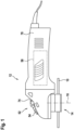
- Fig. 1 shows a machine tool system with a machine tool 12 with a housing 78 and an insert tool 10.
- the machine tool 12 is designed as an angle grinder.
- the insert tool 10 is designed as a grinding wheel.
- the insert tool 10 has a connection device 46 (cf. Fig. 4 ).
- the connection device 46 is designed as a continuous recess 50.
- the machine tool 12 has a quick-clamping device.
- the quick-clamping device is provided for arranging at least one insert tool 10 on the machine tool 12.
- the machine tool 12 has an actuating means 52 for opening and closing the quick-clamping device.
- the actuating means 52 is designed as a pull lever 54.
- the pull lever 54 has an eccentric 74.
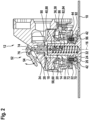
- the actuating means 52 is provided, in particular by means of the eccentric 74, for actuating a release bolt 76 (cf. Fig. 2 ) of the quick-clamping device in the axial direction.
- the release bolt 76 is provided to release the quick-clamping device when the release bolt 76 moves into the housing 78 of the machine tool 12.
- the actuating means 52 shown is in a closed state.
- the machine tool 12 has a drive unit 56.
- the drive unit 56 is at least intended to provide kinetic energy, which is intended to move an insert tool 10, in particular to rotate it.
- the drive unit 56 is arranged in the housing 78.
- the quick-clamping device has an output unit 14.
- the output unit 14 is intended for movement of the insert tool 10 about an output axis 16 of the output unit 14.
- the output unit 14 has an output element 28.
- the output element 28 is designed as a cylindrical hollow shaft.
- the output element 28 is arranged centered around the output axis 16.
- the machine tool 12 has a force transmission element 58 for transmitting, in particular receiving, a force generated by the drive unit 56.
- the force transmission element 58 is designed as a ring gear 60.
- the ring gear 60 is connected in a force-locking manner to the output element 28.
- the Ring gear 60 is connected to the drive unit 56 by means of methods familiar to those skilled in the art, for example a drive pinion and drive shaft (not shown).
- the ring gear 60 can be driven in rotation by the drive unit 56.
- the quick-clamping device has a fixing unit 20.
- the fixing unit 20 is provided for axially fixing the insert tool 10 on the output unit 14.
- the fixing unit 20 has a fixing element 18.
- the fixing element 18 is arranged in a captive manner on the output unit 14, in particular the output element 28, and/or is mounted non-removably on the output unit 14, in particular the output element 28.
- the fixing element 18 has a locking part 66.
- the locking part 66 is formed in one piece with the fixing element 18.
- the locking part 66 is arranged on a lower side facing away from the output unit 14, as seen along the output axis 16.
- the locking part 66 has a contour 48 in the form of an angled cross.
- the locking part 66 is intended to create a positive connection to a holder of an insert tool 10 between the output element 28 and the locking part 66.
- the fixing element 18 is movably mounted.
- the fixing element 18 is movably mounted relative to the output unit 14 around the output axis 16.
- the fixing element 18 is movably mounted relative to the output unit 14 in the direction of the output axis 16.
- the quick-release device has a securing unit 22.
- the securing unit 22 has two securing elements 24.
- a maximum possible axial deflection of the fixing element 18 from a position that can be fixed by the securing element 24 is at most 10 mm.
- the maximum possible axial deflection of the fixing element 18 is predetermined by a pitch of the thread 44 and/or a pitch of the further thread 92.
- the securing element 24 is movably mounted.
- the securing element 24 is provided to secure the fixing element 18 against movement of the fixing element 18 about the output axis 16.
- the securing element 24 prevents rotation of the fixing element 18 by means of a positive connection.
- the securing element 24 is movably mounted on the output element 28 of the output unit 14.
- the securing element 24 is mounted in a sleeve 72 delimited by the output element 28.
- the securing element 24 can be retracted into the sleeve 72 and extended out of the sleeve 72.
- the sleeve 72 is formed in one piece with the output element 28.
- the securing unit 22 has at least one securing spring 30.
- Each securing element 24 of the securing unit 22 has a securing spring 30.
- the securing spring 30 preloads the securing element 24 with a spring force in the direction of a securing position of the securing element 24.
- the Fig. 2 The locking spring 30 shown is in a tensioned state. By means of the locking spring 30, the locking element 24 moves out of the sleeve 72 in the absence of a blockage by the fixing element 18.
- the fixing unit 20 has a tension spring 32.
- the tension spring 32 is arranged within the fixing unit 20, in particular the fixing element 18.
- the tension spring 32 is designed as a compression spring.
- Fig. 2 shows the tension spring 32 in a relaxed state.
- the tension spring 32 generated in at least one operating state (cf. Fig. 3 ) a tension force which, by means of a transmission via the fixing element 18, causes a pressing force on the contact surface 26 of the securing element 24.
- the securing element 24 prevents the tension spring 32 from relaxing in at least one operating state by hindering rotation of the fixing element 18.
- the quick-clamping device has a cam gear 34.
- the cam gear 34 is intended to move the fixing element 18 back and forth at least between two end positions, one of the end positions being a position that can be fixed by the securing unit 22.
- the cam gear 34 has a plurality of cam gear elements 38, 40, 82.
- the output unit 14 has a cam gear element 38.
- the cam gear element 38 of the output unit 14 is designed as a recess 36 in the output element 28.
- the cam gear element 38 of the output unit 14 forms a trajectory 80 that is angled to the output axis 16.
- the fixing unit 20 has a cam gear element 82.
- the cam gear element 82 of the fixing unit 20 is designed as a recess 84 in the fixing element 18.
- the cam gear element 82 of the fixing unit 20 forms a trajectory 86 that is parallel to the output axis 16.
- the cam gear element 40 of the cam gear 34 which is different from the cam gear elements 38, 82 of the output unit 14 and the fixing unit 20, is designed as a movable cam gear element 88.
- the cam gear element 40 of the cam gear 34 is arranged at least partially within the fixing element 18.
- the cam gear element 40 of the cam gear 34 in particular the movable cam gear element 88, is arranged to be axially movable.
- the cam gear element 40 of the cam gear 34 in particular the movable cam gear element 88, is arranged to be rotationally movable.
- the cam gear element 40 of the cam gear 34 in particular the movable cam gear element 88, engages at least partially in the cam gear element 38 of the output unit 14 and/or the cam gear element 82 of the fixing unit 20.
- the cam gear element 40 of the cam gear 34 in particular the movable cam gear element 88, has a contact surface 90 which is used for is intended to rest against the release bolt 76 in at least one operating state.
- Pressing the release bolt 76 into the housing 78 of the machine tool 12 causes an axial deflection of the cam gear element 40 of the cam gear 34, in particular of the movable cam gear element 88. Due to the engaging contact of the movable cam gear element 88 in the cam gear element 38 of the output unit 14, the movable cam gear element 88 follows the angled trajectory 80 of the cam gear element 38 of the output unit 14, which causes a rotational movement of the movable cam gear element 88. The rotational movement of the movable cam gear element 88 engaging in the cam gear element 82 of the fixing unit 20 forces the fixing element 18 arranged between the movable cam gear element 88 and the output unit 14 to rotate.
- the output unit 14 has at least one torque transmission element 42.
- the torque transmission element 42 is provided to transmit a torque from the output unit 14 to an insert tool 10.
- the torque transmission element 42 is formed in one piece with the output element 28.
- the torque transmission element 42 has an outer contour 68 in the form of an angled cross (cf. Fig. 3 ).
- the torque transmission element 42 is provided to form a positive connection with an insert tool 10 by means of the outer contour 68 in the assembled state.
- the outer contour 68 of the torque transmission element 42 is formed in at least one position of the fixing element 18 so as to be congruent with the fixing element 18, in particular the locking part 66 of the fixing element 18 (cf. Fig. 3 ).
- the outer contour 68 of the torque transmission element 42 is designed to be congruent with the connection device 46 of the insert tool 10 in at least one position of the insert tool 10.
- the connection device 46 in particular an inner contour 94 of the connection device 46, is designed to correspond to a contour 48 of the fixing element, in particular the locking part 18 of the quick-release device.
- This rotation causes, in particular by means of the thread 44 and/or the further thread 92, an axial deflection depending on a pitch S of the thread 44 and/or the further thread 92.
- the axial deflection is thus ⁇ / 360 ° * S.
- the tension force of the fixing element 18 is therefore U times greater than the tension force of the tension spring 32.
Landscapes
- Engineering & Computer Science (AREA)
- Mechanical Engineering (AREA)
- Constituent Portions Of Griding Lathes, Driving, Sensing And Control (AREA)
- Finish Polishing, Edge Sharpening, And Grinding By Specific Grinding Devices (AREA)
- Grinding-Machine Dressing And Accessory Apparatuses (AREA)
Applications Claiming Priority (2)
| Application Number | Priority Date | Filing Date | Title |
|---|---|---|---|
| DE102017214117.4A DE102017214117B4 (de) | 2017-08-11 | 2017-08-11 | Schnellspannvorrichtung |
| PCT/EP2018/070744 WO2019030057A1 (de) | 2017-08-11 | 2018-07-31 | Schnellspannvorrichtung |
Publications (2)
| Publication Number | Publication Date |
|---|---|
| EP3664962A1 EP3664962A1 (de) | 2020-06-17 |
| EP3664962B1 true EP3664962B1 (de) | 2024-11-27 |
Family
ID=63079923
Family Applications (1)
| Application Number | Title | Priority Date | Filing Date |
|---|---|---|---|
| EP18749353.1A Active EP3664962B1 (de) | 2017-08-11 | 2018-07-31 | Schnellspannvorrichtung |
Country Status (7)
| Country | Link |
|---|---|
| US (2) | US11607773B2 (ko) |
| EP (1) | EP3664962B1 (ko) |
| JP (1) | JP7101757B2 (ko) |
| KR (1) | KR102566069B1 (ko) |
| CN (2) | CN116021390B (ko) |
| DE (1) | DE102017214117B4 (ko) |
| WO (1) | WO2019030057A1 (ko) |
Families Citing this family (15)
| Publication number | Priority date | Publication date | Assignee | Title |
|---|---|---|---|---|
| CN211029452U (zh) * | 2019-05-29 | 2020-07-17 | 南京德朔实业有限公司 | 电动工具 |
| CN110394736B (zh) * | 2019-07-10 | 2020-05-22 | 三明学院 | 一种大型砂轮锯砂轮片更换系统 |
| CN112775908A (zh) * | 2019-11-08 | 2021-05-11 | 浙江博来工具有限公司 | 一种工作头快装限位结构 |
| DE102019218092A1 (de) * | 2019-11-22 | 2021-05-27 | Robert Bosch Gmbh | Elektromagnetische Betätigungseinrichtung |
| DE102019220539A1 (de) * | 2019-12-23 | 2021-06-24 | Robert Bosch Gmbh | Schnellspannvorrichtung |
| CN111496847B (zh) * | 2020-05-29 | 2023-10-31 | 郑州芯博科技发展有限公司 | 一种快换装配装置 |
| CA3152398A1 (en) | 2021-03-18 | 2022-09-18 | Techtronic Cordless Gp | Mandrel and accessory for rotary tool |
| US20240246189A1 (en) * | 2021-06-08 | 2024-07-25 | Milwaukee Electric Tool Corporation | Power tool having tool-free attachment system |
| CN113334221B (zh) * | 2021-06-17 | 2025-06-03 | 浙江德硕科技股份有限公司 | 抛光机头、抛光机、抛光机的快换头及磨抛头 |
| CN118354883A (zh) * | 2021-11-30 | 2024-07-16 | 罗伯特·博世有限公司 | 工具接口装置,尤其是插入式工具衬套 |
| DE102022204599A1 (de) | 2021-11-30 | 2023-06-01 | Robert Bosch Gesellschaft mit beschränkter Haftung | Werkzeugschnittstellenvorrichtung, insbesondere Einsatzwerkzeugnabe |
| DE102022200952A1 (de) | 2022-01-28 | 2023-08-03 | Robert Bosch Gesellschaft mit beschränkter Haftung | Werkzeugschnittstellenvorrichtung, Einsatzwerkzeug mit einer Werkzeugschnittstellenvorrichtung und Werkzeugmaschinensystem mit einem Einsatzwerkzeug und einer Werkzeugmaschine |
| USD1102495S1 (en) | 2022-03-16 | 2025-11-18 | Techtronic Cordless Gp | Mandrel |
| CN114800263B (zh) * | 2022-04-12 | 2025-09-09 | 嘉兴太微合智造科技有限公司 | 一种用于机械手自动化打磨的磨片快换结构 |
| US20240375188A1 (en) * | 2023-05-12 | 2024-11-14 | Robert Bosch Gmbh | Mandrel Assembly for Use With a Rotary Tool |
Citations (1)
| Publication number | Priority date | Publication date | Assignee | Title |
|---|---|---|---|---|
| DE10017457A1 (de) * | 2000-04-07 | 2001-10-11 | Bosch Gmbh Robert | Schleifmaschinenwerkzeugaufnahme |
Family Cites Families (32)
| Publication number | Priority date | Publication date | Assignee | Title |
|---|---|---|---|---|
| JPS5898163U (ja) | 1981-12-25 | 1983-07-04 | 日本レヂボン株式会社 | スポンジ砥石の装着装置 |
| DE3405885C1 (de) | 1984-02-18 | 1986-01-09 | C. & E. Fein Gmbh & Co, 7000 Stuttgart | Einrichtung zum Befestigen einer Schleifscheibe an der Schleifspindel einer tragbaren Winkelschleifmaschine |
| JPH063187Y2 (ja) | 1984-05-09 | 1994-01-26 | 日本電装株式会社 | 内燃機関の燃料噴射ノズル |
| DE3741484C1 (de) * | 1987-12-08 | 1989-08-24 | Fein C & E | Handwerkzeugmaschine mit automatischer Arretierung der Arbeitsspindel |
| DE4432973B4 (de) | 1994-09-16 | 2009-10-01 | Robert Bosch Gmbh | Elektrische Handwerkzeugmaschine mit einer Spindelarretierung |
| JPH1193164A (ja) | 1997-09-18 | 1999-04-06 | Seijiro Nishioka | 先端鋼管キャップ回転圧入コンクリート杭 |
| JP2000190198A (ja) * | 1998-12-28 | 2000-07-11 | Nisshin Seisakusho:Kk | ホ―ニングツ―ル用アダプタ装置 |
| DE19944564A1 (de) * | 1999-09-17 | 2001-03-22 | Bosch Gmbh Robert | Handwerkzeugmaschine |
| DE10017458A1 (de) * | 2000-04-07 | 2001-10-18 | Bosch Gmbh Robert | Schleifmaschinenwerkzeugaufnahme |
| DE10017981A1 (de) | 2000-04-11 | 2001-10-25 | Bosch Gmbh Robert | Werkzeugaufnahme |
| DE10039739A1 (de) * | 2000-08-16 | 2002-02-28 | C & E Fein Gmbh & Co Kg | Elektrowerkzeug mit Schnellspanneinrichtung |
| US7013987B2 (en) * | 2000-09-08 | 2006-03-21 | Black & Decker | Clutch assembly and clamp mechanism for rotary tool disc |
| DE10361810A1 (de) * | 2003-12-30 | 2005-07-28 | Robert Bosch Gmbh | Handwerkzeugmaschine mit Spanneinrichtung |
| DE102004051031B3 (de) | 2004-10-20 | 2006-04-27 | Ott-Jakob Gmbh & Co. Spanntechnik Kg | Spannvorrichtung |
| JP4406601B2 (ja) | 2004-12-27 | 2010-02-03 | 旭化成株式会社 | 組織幹細胞増殖剤 |
| DE102006001986A1 (de) * | 2006-01-16 | 2007-07-19 | Robert Bosch Gmbh | Spannvorrichtung zum lösbaren Befestigen eines scheibenförmigen Werkzeugs |
| JP4229146B2 (ja) | 2006-06-30 | 2009-02-25 | カシオ計算機株式会社 | ナビゲート装置及びプログラム |
| ATE548157T1 (de) * | 2007-06-06 | 2012-03-15 | No Screw Ltd | Befestigungsmechanismus |
| DE202009001440U1 (de) * | 2009-01-30 | 2010-07-01 | C. & E. Fein Gmbh | Kraftgetriebenes Handwerkzeug mit Spanneinrichtung für ein Werkzeug |
| CN102233537B (zh) * | 2010-04-27 | 2015-03-11 | 南京德朔实业有限公司 | 具有工作元件快速夹紧装置的手持动力工具 |
| DE102010043190A1 (de) | 2010-10-29 | 2012-05-03 | Robert Bosch Gmbh | Handwerkzeugmaschinenspannvorrichtung |
| DE102011003103A1 (de) * | 2011-01-25 | 2012-07-26 | Robert Bosch Gmbh | Werkzeugspannvorrichtung |
| DE102011005821A1 (de) * | 2011-03-18 | 2012-09-20 | Robert Bosch Gmbh | Werkzeugspannvorrichtung |
| DE102011085561A1 (de) | 2011-06-06 | 2012-12-06 | Robert Bosch Gmbh | Handwerkzeugmaschinenspannvorrichtung |
| CN102896619B (zh) * | 2011-07-26 | 2015-04-22 | 苏州宝时得电动工具有限公司 | 动力工具及其操作方法 |
| US9067293B2 (en) * | 2011-09-30 | 2015-06-30 | Robert Bosch Gmbh | Accessory clamp for a power tool |
| JP5746645B2 (ja) * | 2012-02-03 | 2015-07-08 | 株式会社マキタ | 作業工具 |
| DE102012007930A1 (de) * | 2012-04-17 | 2013-10-17 | C. & E. Fein Gmbh | Handwerkzeug |
| DE102012007926A1 (de) * | 2012-04-17 | 2013-10-17 | C. & E. Fein Gmbh | Handwerkzeug mit einer Spannvorrichtung für ein Werkzeug |
| CN203092512U (zh) * | 2012-12-29 | 2013-07-31 | 南京德朔实业有限公司 | 附件夹紧机构及带有该附件夹紧机构的动力工具 |
| DE102013216535B4 (de) | 2013-08-21 | 2024-09-26 | Robert Bosch Gmbh | Handwerkzeugmaschinenwerkzeugaufnahmemodul |
| US20170259348A1 (en) * | 2016-03-09 | 2017-09-14 | Ac (Macao Commercial Offshore) Limited | Toolless blade release mechanism for a power tool |
-
2017
- 2017-08-11 DE DE102017214117.4A patent/DE102017214117B4/de active Active
-
2018
- 2018-07-31 US US16/627,651 patent/US11607773B2/en active Active
- 2018-07-31 EP EP18749353.1A patent/EP3664962B1/de active Active
- 2018-07-31 CN CN202310259720.9A patent/CN116021390B/zh active Active
- 2018-07-31 WO PCT/EP2018/070744 patent/WO2019030057A1/de not_active Ceased
- 2018-07-31 KR KR1020207003870A patent/KR102566069B1/ko active Active
- 2018-07-31 CN CN201880052074.6A patent/CN110997230B/zh active Active
- 2018-07-31 JP JP2020507691A patent/JP7101757B2/ja active Active
-
2023
- 2023-02-21 US US18/171,984 patent/US12420377B2/en active Active
Patent Citations (1)
| Publication number | Priority date | Publication date | Assignee | Title |
|---|---|---|---|---|
| DE10017457A1 (de) * | 2000-04-07 | 2001-10-11 | Bosch Gmbh Robert | Schleifmaschinenwerkzeugaufnahme |
Also Published As
| Publication number | Publication date |
|---|---|
| CN116021390B (zh) | 2026-04-03 |
| JP7101757B2 (ja) | 2022-07-15 |
| EP3664962A1 (de) | 2020-06-17 |
| RU2020109422A (ru) | 2021-09-13 |
| KR20200039687A (ko) | 2020-04-16 |
| CN110997230A (zh) | 2020-04-10 |
| JP2020529336A (ja) | 2020-10-08 |
| US12420377B2 (en) | 2025-09-23 |
| WO2019030057A1 (de) | 2019-02-14 |
| KR102566069B1 (ko) | 2023-08-14 |
| DE102017214117A1 (de) | 2019-02-14 |
| DE102017214117B4 (de) | 2026-02-26 |
| RU2020109422A3 (ko) | 2021-11-16 |
| CN116021390A (zh) | 2023-04-28 |
| US20230191556A1 (en) | 2023-06-22 |
| BR112020002420A2 (pt) | 2020-07-28 |
| US11607773B2 (en) | 2023-03-21 |
| US20200156209A1 (en) | 2020-05-21 |
| CN110997230B (zh) | 2023-03-10 |
Similar Documents
| Publication | Publication Date | Title |
|---|---|---|
| EP3664962B1 (de) | Schnellspannvorrichtung | |
| DE102009054930B4 (de) | Bohrmaschine | |
| EP1737616B1 (de) | Kraftgetriebenes handwerkzeug mit spanneinrichtung für ein werkzeug | |
| EP1307313B1 (de) | Handwerkzeugmaschine | |
| EP2213419A1 (de) | Kraftgetriebenes Handwerkzeug mit Spanneinrichtung für ein Werkzeug | |
| EP2627483B1 (de) | Handgeführtes elektrowerkzeug mit einer spindellockvorrichtung | |
| EP2262619A1 (de) | Zusatzhandgriff sowie handwerkzeugmaschine | |
| EP3664963B1 (de) | Schnellspannvorrichtung für eine, insbesondere zumindest eine rotierend antreibbare abtriebswelle aufweisende, tragbare werkzeugmaschine, insbesondere winkelschleifmaschine | |
| WO2009074384A1 (de) | Scheibenwischerantrieb | |
| WO1990000463A1 (de) | Spanneinrichtung zum axialen festspannen eines werkzeuges, insbesondere einer scheibe | |
| WO2021130026A1 (de) | Schnellspannvorrichtung | |
| DE102006001986A1 (de) | Spannvorrichtung zum lösbaren Befestigen eines scheibenförmigen Werkzeugs | |
| EP2599568A1 (de) | Bohrvorrichtung | |
| EP3965996A1 (de) | Vorsatzgerät und hand-werkzeugmaschine mit vorsatzgerät | |
| EP2478984A1 (de) | Motorarbeitsgerät mit einer Spanneinrichtung für einen Riemen | |
| WO2011018254A1 (de) | Werkzeugmaschine mit einer schutzhaube | |
| EP0990489B1 (de) | Kraftgetriebener Schrauber | |
| CH693405A5 (de) | Elektrohandwerkzeugmaschine. | |
| WO1988004219A1 (fr) | Outillage a main portatif, notamment meuleuse d'angle | |
| WO2017134037A1 (de) | Spannvorrichtung | |
| EP3279492B1 (de) | Spanneinrichtung für werkzeuge | |
| EP1259357A1 (de) | Werkzeugmaschine | |
| DE102019220538A1 (de) | Schnellspannvorrichtung | |
| DE10040332B4 (de) | Elektrowerkzeug mit rotierend angetriebenem Werkzeug und einer Bremsvorrichtung | |
| DE102010064363B4 (de) | Handwerkzeugmaschinenspannvorrichtung mit Verdrehsicherung |
Legal Events
| Date | Code | Title | Description |
|---|---|---|---|
| STAA | Information on the status of an ep patent application or granted ep patent |
Free format text: STATUS: UNKNOWN |
|
| STAA | Information on the status of an ep patent application or granted ep patent |
Free format text: STATUS: THE INTERNATIONAL PUBLICATION HAS BEEN MADE |
|
| PUAI | Public reference made under article 153(3) epc to a published international application that has entered the european phase |
Free format text: ORIGINAL CODE: 0009012 |
|
| STAA | Information on the status of an ep patent application or granted ep patent |
Free format text: STATUS: REQUEST FOR EXAMINATION WAS MADE |
|
| 17P | Request for examination filed |
Effective date: 20200311 |
|
| AK | Designated contracting states |
Kind code of ref document: A1 Designated state(s): AL AT BE BG CH CY CZ DE DK EE ES FI FR GB GR HR HU IE IS IT LI LT LU LV MC MK MT NL NO PL PT RO RS SE SI SK SM TR |
|
| AX | Request for extension of the european patent |
Extension state: BA ME |
|
| DAV | Request for validation of the european patent (deleted) | ||
| DAX | Request for extension of the european patent (deleted) | ||
| STAA | Information on the status of an ep patent application or granted ep patent |
Free format text: STATUS: EXAMINATION IS IN PROGRESS |
|
| 17Q | First examination report despatched |
Effective date: 20221223 |
|
| P01 | Opt-out of the competence of the unified patent court (upc) registered |
Effective date: 20230509 |
|
| GRAP | Despatch of communication of intention to grant a patent |
Free format text: ORIGINAL CODE: EPIDOSNIGR1 |
|
| STAA | Information on the status of an ep patent application or granted ep patent |
Free format text: STATUS: GRANT OF PATENT IS INTENDED |
|
| INTG | Intention to grant announced |
Effective date: 20240717 |
|
| GRAS | Grant fee paid |
Free format text: ORIGINAL CODE: EPIDOSNIGR3 |
|
| GRAA | (expected) grant |
Free format text: ORIGINAL CODE: 0009210 |
|
| STAA | Information on the status of an ep patent application or granted ep patent |
Free format text: STATUS: THE PATENT HAS BEEN GRANTED |
|
| AK | Designated contracting states |
Kind code of ref document: B1 Designated state(s): AL AT BE BG CH CY CZ DE DK EE ES FI FR GB GR HR HU IE IS IT LI LT LU LV MC MK MT NL NO PL PT RO RS SE SI SK SM TR |
|
| REG | Reference to a national code |
Ref country code: GB Ref legal event code: FG4D Free format text: NOT ENGLISH |
|
| REG | Reference to a national code |
Ref country code: CH Ref legal event code: EP |
|
| REG | Reference to a national code |
Ref country code: DE Ref legal event code: R096 Ref document number: 502018015367 Country of ref document: DE |
|
| REG | Reference to a national code |
Ref country code: IE Ref legal event code: FG4D Free format text: LANGUAGE OF EP DOCUMENT: GERMAN |
|
| REG | Reference to a national code |
Ref country code: LT Ref legal event code: MG9D |
|
| REG | Reference to a national code |
Ref country code: NL Ref legal event code: MP Effective date: 20241127 |
|
| PG25 | Lapsed in a contracting state [announced via postgrant information from national office to epo] |
Ref country code: PT Free format text: LAPSE BECAUSE OF FAILURE TO SUBMIT A TRANSLATION OF THE DESCRIPTION OR TO PAY THE FEE WITHIN THE PRESCRIBED TIME-LIMIT Effective date: 20250327 Ref country code: IS Free format text: LAPSE BECAUSE OF FAILURE TO SUBMIT A TRANSLATION OF THE DESCRIPTION OR TO PAY THE FEE WITHIN THE PRESCRIBED TIME-LIMIT Effective date: 20250327 Ref country code: HR Free format text: LAPSE BECAUSE OF FAILURE TO SUBMIT A TRANSLATION OF THE DESCRIPTION OR TO PAY THE FEE WITHIN THE PRESCRIBED TIME-LIMIT Effective date: 20241127 |
|
| PG25 | Lapsed in a contracting state [announced via postgrant information from national office to epo] |
Ref country code: FI Free format text: LAPSE BECAUSE OF FAILURE TO SUBMIT A TRANSLATION OF THE DESCRIPTION OR TO PAY THE FEE WITHIN THE PRESCRIBED TIME-LIMIT Effective date: 20241127 Ref country code: NL Free format text: LAPSE BECAUSE OF FAILURE TO SUBMIT A TRANSLATION OF THE DESCRIPTION OR TO PAY THE FEE WITHIN THE PRESCRIBED TIME-LIMIT Effective date: 20241127 |
|
| PG25 | Lapsed in a contracting state [announced via postgrant information from national office to epo] |
Ref country code: BG Free format text: LAPSE BECAUSE OF FAILURE TO SUBMIT A TRANSLATION OF THE DESCRIPTION OR TO PAY THE FEE WITHIN THE PRESCRIBED TIME-LIMIT Effective date: 20241127 |
|
| PG25 | Lapsed in a contracting state [announced via postgrant information from national office to epo] |
Ref country code: ES Free format text: LAPSE BECAUSE OF FAILURE TO SUBMIT A TRANSLATION OF THE DESCRIPTION OR TO PAY THE FEE WITHIN THE PRESCRIBED TIME-LIMIT Effective date: 20241127 |
|
| PG25 | Lapsed in a contracting state [announced via postgrant information from national office to epo] |
Ref country code: NO Free format text: LAPSE BECAUSE OF FAILURE TO SUBMIT A TRANSLATION OF THE DESCRIPTION OR TO PAY THE FEE WITHIN THE PRESCRIBED TIME-LIMIT Effective date: 20250227 |
|
| PG25 | Lapsed in a contracting state [announced via postgrant information from national office to epo] |
Ref country code: LV Free format text: LAPSE BECAUSE OF FAILURE TO SUBMIT A TRANSLATION OF THE DESCRIPTION OR TO PAY THE FEE WITHIN THE PRESCRIBED TIME-LIMIT Effective date: 20241127 Ref country code: GR Free format text: LAPSE BECAUSE OF FAILURE TO SUBMIT A TRANSLATION OF THE DESCRIPTION OR TO PAY THE FEE WITHIN THE PRESCRIBED TIME-LIMIT Effective date: 20250228 |
|
| PG25 | Lapsed in a contracting state [announced via postgrant information from national office to epo] |
Ref country code: PL Free format text: LAPSE BECAUSE OF FAILURE TO SUBMIT A TRANSLATION OF THE DESCRIPTION OR TO PAY THE FEE WITHIN THE PRESCRIBED TIME-LIMIT Effective date: 20241127 |
|
| PG25 | Lapsed in a contracting state [announced via postgrant information from national office to epo] |
Ref country code: RS Free format text: LAPSE BECAUSE OF FAILURE TO SUBMIT A TRANSLATION OF THE DESCRIPTION OR TO PAY THE FEE WITHIN THE PRESCRIBED TIME-LIMIT Effective date: 20250227 |
|
| PG25 | Lapsed in a contracting state [announced via postgrant information from national office to epo] |
Ref country code: SM Free format text: LAPSE BECAUSE OF FAILURE TO SUBMIT A TRANSLATION OF THE DESCRIPTION OR TO PAY THE FEE WITHIN THE PRESCRIBED TIME-LIMIT Effective date: 20241127 |
|
| PG25 | Lapsed in a contracting state [announced via postgrant information from national office to epo] |
Ref country code: DK Free format text: LAPSE BECAUSE OF FAILURE TO SUBMIT A TRANSLATION OF THE DESCRIPTION OR TO PAY THE FEE WITHIN THE PRESCRIBED TIME-LIMIT Effective date: 20241127 |
|
| PG25 | Lapsed in a contracting state [announced via postgrant information from national office to epo] |
Ref country code: EE Free format text: LAPSE BECAUSE OF FAILURE TO SUBMIT A TRANSLATION OF THE DESCRIPTION OR TO PAY THE FEE WITHIN THE PRESCRIBED TIME-LIMIT Effective date: 20241127 |
|
| PG25 | Lapsed in a contracting state [announced via postgrant information from national office to epo] |
Ref country code: RO Free format text: LAPSE BECAUSE OF FAILURE TO SUBMIT A TRANSLATION OF THE DESCRIPTION OR TO PAY THE FEE WITHIN THE PRESCRIBED TIME-LIMIT Effective date: 20241127 |
|
| PG25 | Lapsed in a contracting state [announced via postgrant information from national office to epo] |
Ref country code: SK Free format text: LAPSE BECAUSE OF FAILURE TO SUBMIT A TRANSLATION OF THE DESCRIPTION OR TO PAY THE FEE WITHIN THE PRESCRIBED TIME-LIMIT Effective date: 20241127 |
|
| PG25 | Lapsed in a contracting state [announced via postgrant information from national office to epo] |
Ref country code: CZ Free format text: LAPSE BECAUSE OF FAILURE TO SUBMIT A TRANSLATION OF THE DESCRIPTION OR TO PAY THE FEE WITHIN THE PRESCRIBED TIME-LIMIT Effective date: 20241127 |
|
| PG25 | Lapsed in a contracting state [announced via postgrant information from national office to epo] |
Ref country code: IT Free format text: LAPSE BECAUSE OF FAILURE TO SUBMIT A TRANSLATION OF THE DESCRIPTION OR TO PAY THE FEE WITHIN THE PRESCRIBED TIME-LIMIT Effective date: 20241127 |
|
| REG | Reference to a national code |
Ref country code: DE Ref legal event code: R097 Ref document number: 502018015367 Country of ref document: DE |
|
| PG25 | Lapsed in a contracting state [announced via postgrant information from national office to epo] |
Ref country code: SE Free format text: LAPSE BECAUSE OF FAILURE TO SUBMIT A TRANSLATION OF THE DESCRIPTION OR TO PAY THE FEE WITHIN THE PRESCRIBED TIME-LIMIT Effective date: 20241127 |
|
| PLBE | No opposition filed within time limit |
Free format text: ORIGINAL CODE: 0009261 |
|
| STAA | Information on the status of an ep patent application or granted ep patent |
Free format text: STATUS: NO OPPOSITION FILED WITHIN TIME LIMIT |
|
| REG | Reference to a national code |
Ref country code: CH Ref legal event code: L10 Free format text: ST27 STATUS EVENT CODE: U-0-0-L10-L00 (AS PROVIDED BY THE NATIONAL OFFICE) Effective date: 20251008 |
|
| PGFP | Annual fee paid to national office [announced via postgrant information from national office to epo] |
Ref country code: DE Payment date: 20250924 Year of fee payment: 8 |
|
| PGFP | Annual fee paid to national office [announced via postgrant information from national office to epo] |
Ref country code: GB Payment date: 20250724 Year of fee payment: 8 |
|
| PGFP | Annual fee paid to national office [announced via postgrant information from national office to epo] |
Ref country code: FR Payment date: 20250723 Year of fee payment: 8 |
|
| 26N | No opposition filed |
Effective date: 20250828 |
|
| REG | Reference to a national code |
Ref country code: CH Ref legal event code: H13 Free format text: ST27 STATUS EVENT CODE: U-0-0-H10-H13 (AS PROVIDED BY THE NATIONAL OFFICE) Effective date: 20260224 |
|
| PG25 | Lapsed in a contracting state [announced via postgrant information from national office to epo] |
Ref country code: LU Free format text: LAPSE BECAUSE OF NON-PAYMENT OF DUE FEES Effective date: 20250731 |
|
| REG | Reference to a national code |
Ref country code: BE Ref legal event code: MM Effective date: 20250731 |
|
| PG25 | Lapsed in a contracting state [announced via postgrant information from national office to epo] |
Ref country code: BE Free format text: LAPSE BECAUSE OF NON-PAYMENT OF DUE FEES Effective date: 20250731 |
|
| PG25 | Lapsed in a contracting state [announced via postgrant information from national office to epo] |
Ref country code: CH Free format text: LAPSE BECAUSE OF NON-PAYMENT OF DUE FEES Effective date: 20250731 |