EP3665032B1 - Dispositif de commande d'une force de contact d'un collecteur de courant avec une vanne relais - Google Patents
Dispositif de commande d'une force de contact d'un collecteur de courant avec une vanne relais Download PDFInfo
- Publication number
- EP3665032B1 EP3665032B1 EP18737207.3A EP18737207A EP3665032B1 EP 3665032 B1 EP3665032 B1 EP 3665032B1 EP 18737207 A EP18737207 A EP 18737207A EP 3665032 B1 EP3665032 B1 EP 3665032B1
- Authority
- EP
- European Patent Office
- Prior art keywords
- pressure
- pilot control
- control circuit
- pilot
- pressures
- Prior art date
- Legal status (The legal status is an assumption and is not a legal conclusion. Google has not performed a legal analysis and makes no representation as to the accuracy of the status listed.)
- Active
Links
Images
Classifications
-
- B—PERFORMING OPERATIONS; TRANSPORTING
- B60—VEHICLES IN GENERAL
- B60L—PROPULSION OF ELECTRICALLY-PROPELLED VEHICLES; SUPPLYING ELECTRIC POWER FOR AUXILIARY EQUIPMENT OF ELECTRICALLY-PROPELLED VEHICLES; ELECTRODYNAMIC BRAKE SYSTEMS FOR VEHICLES IN GENERAL; MAGNETIC SUSPENSION OR LEVITATION FOR VEHICLES; MONITORING OPERATING VARIABLES OF ELECTRICALLY-PROPELLED VEHICLES; ELECTRIC SAFETY DEVICES FOR ELECTRICALLY-PROPELLED VEHICLES
- B60L5/00—Current collectors for power supply lines of electrically-propelled vehicles
-
- F—MECHANICAL ENGINEERING; LIGHTING; HEATING; WEAPONS; BLASTING
- F15—FLUID-PRESSURE ACTUATORS; HYDRAULICS OR PNEUMATICS IN GENERAL
- F15B—SYSTEMS ACTING BY MEANS OF FLUIDS IN GENERAL; FLUID-PRESSURE ACTUATORS, e.g. SERVOMOTORS; DETAILS OF FLUID-PRESSURE SYSTEMS, NOT OTHERWISE PROVIDED FOR
- F15B11/00—Servomotor systems without provision for follow-up action; Circuits therefor
- F15B11/02—Systems essentially incorporating special features for controlling the speed or actuating force of an output member
- F15B11/028—Systems essentially incorporating special features for controlling the speed or actuating force of an output member for controlling the actuating force
-
- B—PERFORMING OPERATIONS; TRANSPORTING
- B60—VEHICLES IN GENERAL
- B60L—PROPULSION OF ELECTRICALLY-PROPELLED VEHICLES; SUPPLYING ELECTRIC POWER FOR AUXILIARY EQUIPMENT OF ELECTRICALLY-PROPELLED VEHICLES; ELECTRODYNAMIC BRAKE SYSTEMS FOR VEHICLES IN GENERAL; MAGNETIC SUSPENSION OR LEVITATION FOR VEHICLES; MONITORING OPERATING VARIABLES OF ELECTRICALLY-PROPELLED VEHICLES; ELECTRIC SAFETY DEVICES FOR ELECTRICALLY-PROPELLED VEHICLES
- B60L5/00—Current collectors for power supply lines of electrically-propelled vehicles
- B60L5/18—Current collectors for power supply lines of electrically-propelled vehicles using bow-type collectors in contact with trolley wire
- B60L5/22—Supporting means for the contact bow
- B60L5/28—Devices for lifting and resetting the collector
- B60L5/32—Devices for lifting and resetting the collector using fluid pressure
-
- G—PHYSICS
- G05—CONTROLLING; REGULATING
- G05D—SYSTEMS FOR CONTROLLING OR REGULATING NON-ELECTRIC VARIABLES
- G05D16/00—Control of fluid pressure
- G05D16/20—Control of fluid pressure characterised by the use of electric means
- G05D16/2006—Control of fluid pressure characterised by the use of electric means with direct action of electric energy on controlling means
- G05D16/2013—Control of fluid pressure characterised by the use of electric means with direct action of electric energy on controlling means using throttling means as controlling means
-
- G—PHYSICS
- G05—CONTROLLING; REGULATING
- G05D—SYSTEMS FOR CONTROLLING OR REGULATING NON-ELECTRIC VARIABLES
- G05D16/00—Control of fluid pressure
- G05D16/20—Control of fluid pressure characterised by the use of electric means
- G05D16/2006—Control of fluid pressure characterised by the use of electric means with direct action of electric energy on controlling means
- G05D16/2013—Control of fluid pressure characterised by the use of electric means with direct action of electric energy on controlling means using throttling means as controlling means
- G05D16/2024—Control of fluid pressure characterised by the use of electric means with direct action of electric energy on controlling means using throttling means as controlling means the throttling means being a multiple-way valve
-
- H—ELECTRICITY
- H01—ELECTRIC ELEMENTS
- H01R—ELECTRICALLY-CONDUCTIVE CONNECTIONS; STRUCTURAL ASSOCIATIONS OF A PLURALITY OF MUTUALLY-INSULATED ELECTRICAL CONNECTING ELEMENTS; COUPLING DEVICES; CURRENT COLLECTORS
- H01R41/00—Non-rotary current collectors for maintaining contact between moving and stationary parts of an electric circuit
-
- B—PERFORMING OPERATIONS; TRANSPORTING
- B60—VEHICLES IN GENERAL
- B60L—PROPULSION OF ELECTRICALLY-PROPELLED VEHICLES; SUPPLYING ELECTRIC POWER FOR AUXILIARY EQUIPMENT OF ELECTRICALLY-PROPELLED VEHICLES; ELECTRODYNAMIC BRAKE SYSTEMS FOR VEHICLES IN GENERAL; MAGNETIC SUSPENSION OR LEVITATION FOR VEHICLES; MONITORING OPERATING VARIABLES OF ELECTRICALLY-PROPELLED VEHICLES; ELECTRIC SAFETY DEVICES FOR ELECTRICALLY-PROPELLED VEHICLES
- B60L2200/00—Type of vehicles
- B60L2200/26—Rail vehicles
-
- F—MECHANICAL ENGINEERING; LIGHTING; HEATING; WEAPONS; BLASTING
- F15—FLUID-PRESSURE ACTUATORS; HYDRAULICS OR PNEUMATICS IN GENERAL
- F15B—SYSTEMS ACTING BY MEANS OF FLUIDS IN GENERAL; FLUID-PRESSURE ACTUATORS, e.g. SERVOMOTORS; DETAILS OF FLUID-PRESSURE SYSTEMS, NOT OTHERWISE PROVIDED FOR
- F15B2211/00—Circuits for servomotor systems
- F15B2211/50—Pressure control
- F15B2211/52—Pressure control characterised by the type of actuation
- F15B2211/528—Pressure control characterised by the type of actuation actuated by fluid pressure
-
- F—MECHANICAL ENGINEERING; LIGHTING; HEATING; WEAPONS; BLASTING
- F15—FLUID-PRESSURE ACTUATORS; HYDRAULICS OR PNEUMATICS IN GENERAL
- F15B—SYSTEMS ACTING BY MEANS OF FLUIDS IN GENERAL; FLUID-PRESSURE ACTUATORS, e.g. SERVOMOTORS; DETAILS OF FLUID-PRESSURE SYSTEMS, NOT OTHERWISE PROVIDED FOR
- F15B2211/00—Circuits for servomotor systems
- F15B2211/60—Circuit components or control therefor
- F15B2211/63—Electronic controllers
- F15B2211/6303—Electronic controllers using input signals
- F15B2211/6306—Electronic controllers using input signals representing a pressure
- F15B2211/6313—Electronic controllers using input signals representing a pressure the pressure being a load pressure
-
- F—MECHANICAL ENGINEERING; LIGHTING; HEATING; WEAPONS; BLASTING
- F15—FLUID-PRESSURE ACTUATORS; HYDRAULICS OR PNEUMATICS IN GENERAL
- F15B—SYSTEMS ACTING BY MEANS OF FLUIDS IN GENERAL; FLUID-PRESSURE ACTUATORS, e.g. SERVOMOTORS; DETAILS OF FLUID-PRESSURE SYSTEMS, NOT OTHERWISE PROVIDED FOR
- F15B2211/00—Circuits for servomotor systems
- F15B2211/60—Circuit components or control therefor
- F15B2211/67—Methods for controlling pilot pressure
-
- H—ELECTRICITY
- H01—ELECTRIC ELEMENTS
- H01R—ELECTRICALLY-CONDUCTIVE CONNECTIONS; STRUCTURAL ASSOCIATIONS OF A PLURALITY OF MUTUALLY-INSULATED ELECTRICAL CONNECTING ELEMENTS; COUPLING DEVICES; CURRENT COLLECTORS
- H01R2201/00—Connectors or connections adapted for particular applications
- H01R2201/26—Connectors or connections adapted for particular applications for vehicles
Definitions
- the invention relates to a device for controlling a contact force of a current collector of a vehicle (for example a traction vehicle) on a contact line with a relay valve, a method for implementing such a device and a vehicle with at least one such device.
- a vehicle for example a traction vehicle
- the overhead line is a conventional or innovative overhead line, such as overhead conductor rails.
- the necessary contact forces increase sharply, particularly at high speeds (>200 km/h), to about twice the standstill value.
- the current state of the art uses wind deflectors in the pantograph, which on the one hand provide an additional aerodynamic force and on the other hand compensate for dynamic lift forces.
- the disadvantage here is that the design and handling of these wind deflectors cannot be easily adapted to different operating situations.
- the additional aerodynamic force in high-speed tunnels is significantly higher than on open track.
- this additional force also depends on the vehicle shape, tunnel cross-section, blocking dimension (ratio of vehicle cross-section to tunnel cross-section), cross-section jumps and position of the pantograph in the train. This additional force also depends on the direction of travel. (for example, depending on the skewer or knee path of an asymmetrical single-arm pantograph).
- pantograph contact force when the train is stationary in order to avoid overheating and damage to the contact strip and overhead line wire at the contact point when there is high current flow from lighting, air conditioning and passenger information systems on vehicles provided.
- wind deflectors cannot provide additional force when the locomotive is stationary.
- the current state of the art includes single-stage and two-stage (fixed but adjustable) pressures that press the pantograph onto the overhead line using a volume-variable lifting bellows.
- electro-pneumatic (ep) controlled pressure controls are already used, as shown in 2.8.
- EP1 539 528 A1 are known. It shows how the fallback level required by railway operators is implemented via a switching valve in the event of a fault in the ep controller.
- an ep controller is switched to a fixed, adjustable pressure reducing valve.
- the ep controller controls the contact pressure in the normal operation of the traction vehicle.
- the disadvantage here is that the contact pressure cannot be controlled precisely enough via the controller and high air consumption is caused.
- a pneumatic control of a current collector with a pressure control means for regulating the contact pressure is known, whereby a pilot control signal is fed to the pressure control means as a setpoint signal and thus the contact pressure of the current collector on an electrical line can be adapted to the circumstances of the respective driving situation,
- the invention is therefore based on the object of creating a device which carries out a more precise control of the required contact forces between a pantograph and a contact line, which are better suited to different operating situations.
- the solution to the problem consists in a device for controlling a contact force between a contact line and a pantograph of a vehicle, which is operated pneumatically or hydraulically.
- Air or oil for example, can be used as pressure media.
- the media pressure is in equilibrium with the gravity (weight) of the pantograph.
- the required contact force is achieved by increasing the working pressure, which is made possible by controlling or regulating a power pressure using two pilot pressures from a pilot circuit. If the operating situation requires an additional contact force, the pilot pressure in the pilot circuit is adjusted to control the power pressure and increase the working pressure.
- the device has a relay valve, which has at least two inputs for the pilot pressures with a small cross section and one input for the power pressure and one output for the working pressure with large cross sections, so that a transmission ratio is provided. An addition of several pilot pressures takes place at the inputs of the relay valve in order to control a power pressure.
- the pilot control circuit has a basic control circuit including a basic control device (e.g. a pressure reducing valve) for setting a first pilot pressure (a basic pilot pressure), an additional control circuit including an additional control device (e.g. a regulator) for setting a second pilot pressure and an adjustment device including a relay valve for controlling the power pressure and for providing the working pressure.
- a basic control device e.g. a pressure reducing valve
- an additional control circuit e.g. a regulator
- an adjustment device including a relay valve for controlling the power pressure and for providing the working pressure.
- a working pressure control circuit is provided which determines whether the working pressure is quickly or slowly increased to the pantograph.
- the working pressure control circuit can be configured to limit the working pressure to a maximum value in order to avoid excessive pressure on the pantograph or the contact line in order to prevent damage.
- the relay valve is designed in such a way that two inputs are provided for two pilot pressures, each with a small cross-section, and one input for the power pressure and one output for the working pressure with large cross-sections are provided so that a highly dynamic pilot pressure control can usually be translated 1:1 to the high-volume working pressure.
- a transmission ratio other than 1:1 can be implemented in one design variant. For example, if the transmission ratio 1:5 is selected, 10 bar in the pilot circuit has an effect on an output pressure of 2 bar at the output of the relay valve. In this case, a deviation is also reduced proportionally.
- the deviation in the pilot circuit is ⁇ 0.1 bar
- the deviation in the output of the relay valve is only ⁇ 0.02 bar, which corresponds to an absolute reduction in the deviation, and thus enables an increase in control accuracy and a reduction in hysteresis.
- the pilot control circuit preferably has a pressure sensor and two control valves.
- the pressure sensor is provided to provide pressure signals to the controller of the pilot control circuit. Due to the small control volume of the pilot control circuit, the higher dynamics can contribute to achieving greater control accuracy.
- the high resolution of the pressure sensor enables a low control level (low pressures) of the controller of the additional control circuit, and this enables a smaller tolerance (higher control accuracy) to be achieved with a smaller hysteresis.
- a constant control volume is always available to the pilot circuit because the variable working volume is separated from the relay valve.
- the pilot circuit regulator can adjust the pressure more precisely than a direct variable volume working pressure regulator.
- a state machine is provided to monitor the controller, among other things, in order to monitor the working pressure to see whether it falls below a minimum pressure setting, exceeds a maximum pressure setting, or deviates from a range between the target and actual value. If one of these cases occurs, a quick shutdown takes place.
- the quick shutdown acts on the pilot control circuit.
- a certain quick shutdown working pressure can be set.
- the quick shutdown can also act on the power pressure and thus prevent the supply to the relay valve, whereby the working pressure is released in any case.
- a state machine for example, an electrical, electronic or microprocessor unit (if necessary with software classified according to a safety level) can be used to monitor the working pressure. Comparison signals for this monitoring device can be obtained from the pressure sensor of the additional control circuit and/or a pressure sensor provided for the working pressure.
- Another advantage of the invention is that the device is designed in such a way that no consumption of pressure media occurs when the contact pressure remains unchanged, thus avoiding constant media consumption, which causes a high number of compressor running cycles in the vehicle, which lead to significant energy waste, noise generation and wear on the compressor.
- the resulting energy efficiency ensures the energy supply to the vehicle, especially when significant amounts of energy are required for lighting and air conditioning via the power collector to the vehicle.
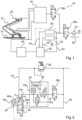
- Fig. 1 shows a part of a vehicle 10, a pantograph 12, a contact line 20 and a control device 22 of the pantograph 12.
- the pressure medium air flows in the inflow direction 90 from a pressure inlet 24 via an air filter 34 into the control device 22.
- control device 22 When the vehicle 10 is in operation or standby mode, the control device 22 is switched on via a switching valve 28a.
- a switching valve 28b and a device 30 represent monitoring devices.
- a certain contact pressure is required between the pantograph 12 and the overhead line 20 in order to ensure a safe transfer of energy from the overhead line 20 via the pantograph 12 to the vehicle 10.
- This working pressure is achieved by a pilot control circuit 32 with an adjustment device 50 and then controlled by a working pressure control circuit 60.
- the pilot control circuit 32 has a base control circuit 56, an additional control circuit 26 and an adjusting device 50.
- a power pressure is supplied to a first pressure medium line 52, the base control circuit 56 and the additional control circuit 26.
- the base control circuit 56 sets a first pilot pressure (base pilot pressure) and the additional control circuit 26 sets a second pilot pressure, wherein the first pilot pressure and the second pilot pressure are each fed via a second pressure medium line 54 to the adjusting device 50 in order to control the power pressure from the first pressure medium line 52 therein.
- Fig. 2 shows a pilot control circuit 32 of the control device 22 according to a first embodiment of the invention.
- the pilot control circuit 32 has a Pressure reducing valve 36, a changeover valve 280, an additional control circuit 26 including a regulator 38, a pressure sensor 72a, a first control valve 76 for pressure reduction, a second control valve 78 for pressure build-up, a relay valve 40 and a pressure sensor 72b.
- the pressure reducing valve 36 is designed to adjust the first pilot pressure (basic pilot pressure) and the regulator 38 is designed to adjust the second pilot pressure (additional pilot pressure), the basic pilot pressure and the additional pilot pressure being each led via the second pressure medium line 54 to inlets 46a and 46b of the relay valve 40.
- the relay valve 40 is designed such that an addition of the pilot pressures takes place after the inlets 46a and 46b in order to control the power pressure from the first pressure medium line 52 with the added pilot pressure and to discharge the working pressure from an outlet 42 of the relay valve 40.
- the changeover valve 28c is provided to switch off the additional control circuit in an emergency.
- the pressure sensors 723 and 72b are provided to measure the additional pilot pressure in the additional control circuit 26 and the working pressure at the outlet 42 of the relay valve.
Landscapes
- Engineering & Computer Science (AREA)
- Physics & Mathematics (AREA)
- Fluid Mechanics (AREA)
- Mechanical Engineering (AREA)
- Power Engineering (AREA)
- Transportation (AREA)
- General Physics & Mathematics (AREA)
- Automation & Control Theory (AREA)
- General Engineering & Computer Science (AREA)
- Current-Collector Devices For Electrically Propelled Vehicles (AREA)
- Fluid-Pressure Circuits (AREA)
- Electric Propulsion And Braking For Vehicles (AREA)
Claims (10)
- Dispositif (22) de commande d'une force de contact d'un collecteur de courant (12) d'un véhicule (10) sur une ligne aérienne (20), dans lequel la force de contact est actionnée au moyen d'une pression de travail pneumatique ou hydraulique, dans lequel le dispositif (22) présente :- un circuit de commande de pilotage (32) et un circuit de commande de pression de travail (60) ;- une vanne relais (40) qui est configurée pour commander une pression de puissance mise à disposition en fonction de deux pressions de commande de pilotage et la délivrer en tant que pression de travail dans le circuit de commande de pression de travail (60),dans lequel la vanne relais (40) présente au moins deux entrées (46, 46a, 46b) pour les pressions de commande de pilotage avec une petite section transversale, et présente une entrée pour la pression de puissance et une sortie (42) pour la pression de travail avec de grandes sections transversales, de sorte qu'un rapport de transmission soit prévu, dans lequel au moins deux entrées (46a, 46b) sont prévues sur la vanne relais (40) côté pressions de commande de pilotage, etcaractérisé en ce que la vanne relais est configurée de sorte qu'une addition de plusieurs pressions de commande de pilotage ait lieu au niveau des entrées pour commander la pression de puissance.
- Dispositif (22) selon la revendication précédente, dans lequel le rapport de transmission de la vanne relais est prévu avec un rapport de transmission autre que 1:1, dans lequel le rapport de transmission est sélectionné de manière à augmenter ou à diminuer.
- Dispositif (22) selon l'une quelconque des revendications précédentes, caractérisé en ce qu'un dispositif de commande de base d'un circuit de commande de base (56) est formé par une vanne de réduction de pression (36) pour régler une première pression de commande de pilotage.
- Dispositif (22) selon l'une quelconque des revendications précédentes, caractérisé en ce qu'un dispositif de commande auxiliaire d'un circuit de commande supplémentaire (26) est formé par un régulateur (38) pour régler une seconde pression de commande de pilotage.
- Dispositif (22) selon l'une quelconque des revendications précédentes, caractérisé en ce qu'une vanne de commutation (28a) est prévue en tant que vanne d'activation et de désactivation dans le circuit de pression de puissance, en amont d'un point d'introduction de la pression de puissance dans le circuit de commande de pilotage (32) et dans le circuit de commande de pression de travail (60).
- Dispositif (22) selon l'une quelconque des revendications précédentes, caractérisé en ce qu'un automate d'état est prévu pour surveiller la pression de travail, qui est configuré de sorte qu'il effectue une coupure des pressions de commande de pilotage, de préférence des pressions de commande de pilotage régulées, dans des situations à définir.
- Dispositif (22) selon l'une quelconque des revendications 1 à 5, caractérisé en ce qu'une unité électrique, électronique ou à microprocesseur est prévue pour surveiller la pression de travail, qui est configurée de sorte qu'elle effectue une coupure des pressions de commande de pilotage, de préférence des pressions de pilotages régulées, dans des situations à définir.
- Dispositif (22) selon l'une quelconque des revendications précédentes, caractérisé en ce que le circuit de commande supplémentaire (26) présente un régulateur (38), un capteur de pression (72a) et deux vannes de régulation (76, 78) avec lesquelles la première pression de commande de pilotage peut être calibrée dans les deux directions.
- Procédé de commande d'une force de contact d'un collecteur de courant (12) d'un véhicule (10) sur une ligne aérienne (20), dans lequel la force de contact est actionnée au moyen d'une pression de puissance pneumatique ou hydraulique, dans lequel la pression de puissance est régulée par des pressions de commande de pilotage d'un circuit de commande pilotage, avec les étapes suivantes :- réglage d'une première pression de commande de pilotage dans le circuit de commande de pilotage pour régler la force de contact normale,- réglage d'une seconde pression de commande de pilotage dans le circuit de commande de pilotage pour régler une force de contact supplémentaire, et- réglage de la pression de puissance au moyen des pressions de commande de pilotage et du rapport de transmission, caractérisé par- une addition des pressions de commande de pilotage en fonction de la situation de conduite respective.
- Véhicule (10) avec au moins un dispositif (22) selon l'une quelconque des revendications 1 à 8.
Applications Claiming Priority (2)
| Application Number | Priority Date | Filing Date | Title |
|---|---|---|---|
| DE102017214115.8A DE102017214115A1 (de) | 2017-08-11 | 2017-08-11 | Vorrichtung zur Steuerung einer Anpresskraft eines Stromabnehmers mit einem Relaisventil |
| PCT/EP2018/067499 WO2019029902A1 (fr) | 2017-08-11 | 2018-06-28 | Dispositif de commande d'une force de contact d'un collecteur de courant avec une vanne relais |
Publications (2)
| Publication Number | Publication Date |
|---|---|
| EP3665032A1 EP3665032A1 (fr) | 2020-06-17 |
| EP3665032B1 true EP3665032B1 (fr) | 2024-10-30 |
Family
ID=62816532
Family Applications (1)
| Application Number | Title | Priority Date | Filing Date |
|---|---|---|---|
| EP18737207.3A Active EP3665032B1 (fr) | 2017-08-11 | 2018-06-28 | Dispositif de commande d'une force de contact d'un collecteur de courant avec une vanne relais |
Country Status (8)
| Country | Link |
|---|---|
| US (1) | US11371536B2 (fr) |
| EP (1) | EP3665032B1 (fr) |
| JP (1) | JP6997292B2 (fr) |
| CN (1) | CN110997392B (fr) |
| DE (1) | DE102017214115A1 (fr) |
| ES (1) | ES3002217T3 (fr) |
| RU (1) | RU2733670C1 (fr) |
| WO (1) | WO2019029902A1 (fr) |
Families Citing this family (2)
| Publication number | Priority date | Publication date | Assignee | Title |
|---|---|---|---|---|
| DE102017214111A1 (de) * | 2017-08-11 | 2019-02-14 | Knorr-Bremse Systeme für Schienenfahrzeuge GmbH | Elektropneumatisch geregelte Ansteuerung eines Stromabnehmers |
| CN110126626A (zh) * | 2019-05-07 | 2019-08-16 | 上海福豆机械成套设备有限公司 | 一种单缸脚踏式升弓泵 |
Citations (1)
| Publication number | Priority date | Publication date | Assignee | Title |
|---|---|---|---|---|
| EP1539528B1 (fr) * | 2002-09-18 | 2008-10-29 | Bombardier Transportation GmbH | Dispositif de regulation electrofluidique et procede permettant de reguler un collecteur de courant electrique |
Family Cites Families (12)
| Publication number | Priority date | Publication date | Assignee | Title |
|---|---|---|---|---|
| JPS605121B2 (ja) * | 1979-05-21 | 1985-02-08 | 富士電機株式会社 | パンタグラフ |
| FR2646381B1 (fr) * | 1989-04-28 | 1991-07-26 | Faiveley Sa | Dispositif pour regler la force d'appui d'un pantographe sur un fil catenaire et procede s'y rapportant |
| DE19643284C2 (de) * | 1996-10-21 | 2000-08-31 | Daimler Chrysler Ag | Vorrichtung zur Verminderung der Kontaktkraftschwankungen zwischen einem Stromabnehmer und einer Fahrleitung |
| DE10126042A1 (de) * | 2000-06-06 | 2002-01-24 | Siemens Ag Oesterreich | Pneumatische Steuerung eines Stromabnehmers elektrischer Triebfahrzeuge |
| DE60215855T2 (de) * | 2001-08-31 | 2007-06-06 | Torotrak (Development) Ltd., Leyland | Stufenloses Getriebe und sein Steuerverfahren |
| DE102004055030B4 (de) | 2004-11-15 | 2009-09-10 | Knorr-Bremse Systeme für Nutzfahrzeuge GmbH | Vorrichtung zur Beaufschlagung eines Kolbenstellers mit Druck |
| FR2901513B1 (fr) | 2006-05-29 | 2016-09-16 | Faiveley Transport | Systeme de commande d'un pantographe, procede mis en oeuvre et module de commande d'un tel systeme |
| US8187147B2 (en) * | 2008-03-27 | 2012-05-29 | GM Global Technology Operations LLC | Hydraulic control system for multi-mode hybrid transmission and method of regulating the same |
| DE102011003144A1 (de) * | 2011-01-26 | 2012-07-26 | Robert Bosch Gmbh | Steuervorrichtung für ein Bremssystem eines Fahrzeugs, Bremssystem und Verfahren zum Betreiben eines Bremssystems für ein Fahrzeug |
| DE102011107061A1 (de) * | 2011-07-11 | 2013-01-17 | Linde Material Handling Gmbh | Antriebsstrang eines Fahrzeugs, insbesondere einer mobilen Arbeitsmaschine |
| RU115725U1 (ru) * | 2011-12-26 | 2012-05-10 | Федеральное государственное бюджетное образовательное учреждение высшего профессионального образования Омский государственный университет путей сообщения (ОмГУПС (ОмИИТ)) | Асимметричный токоприемник электроподвижного состава |
| DE102013217429A1 (de) | 2013-09-02 | 2015-03-05 | Siemens Aktiengesellschaft | Druckluftsystem |
-
2017
- 2017-08-11 DE DE102017214115.8A patent/DE102017214115A1/de not_active Ceased
-
2018
- 2018-06-28 EP EP18737207.3A patent/EP3665032B1/fr active Active
- 2018-06-28 JP JP2020507577A patent/JP6997292B2/ja active Active
- 2018-06-28 ES ES18737207T patent/ES3002217T3/es active Active
- 2018-06-28 CN CN201880052114.7A patent/CN110997392B/zh active Active
- 2018-06-28 RU RU2020110059A patent/RU2733670C1/ru active
- 2018-06-28 WO PCT/EP2018/067499 patent/WO2019029902A1/fr not_active Ceased
- 2018-06-28 US US16/638,666 patent/US11371536B2/en active Active
Patent Citations (1)
| Publication number | Priority date | Publication date | Assignee | Title |
|---|---|---|---|---|
| EP1539528B1 (fr) * | 2002-09-18 | 2008-10-29 | Bombardier Transportation GmbH | Dispositif de regulation electrofluidique et procede permettant de reguler un collecteur de courant electrique |
Also Published As
| Publication number | Publication date |
|---|---|
| RU2733670C1 (ru) | 2020-10-06 |
| JP2020529824A (ja) | 2020-10-08 |
| JP6997292B2 (ja) | 2022-01-17 |
| DE102017214115A1 (de) | 2019-02-14 |
| WO2019029902A1 (fr) | 2019-02-14 |
| ES3002217T3 (en) | 2025-03-06 |
| EP3665032A1 (fr) | 2020-06-17 |
| US20200271135A1 (en) | 2020-08-27 |
| CN110997392A (zh) | 2020-04-10 |
| US11371536B2 (en) | 2022-06-28 |
| CN110997392B (zh) | 2024-02-06 |
Similar Documents
| Publication | Publication Date | Title |
|---|---|---|
| EP2109550B1 (fr) | Train à sustentation magnétique et son procédé d'exploitation | |
| EP2688779B1 (fr) | Actionneur pour un système de freinage d'un véhicule ferroviaire | |
| DE102008027474B4 (de) | Stellglied sowie Drehgestellsteuerung | |
| EP3013624B1 (fr) | Système à air comprimé | |
| EP0320602B1 (fr) | Dispositif d'avertissement de surcharge pour frein de remorque | |
| EP2855223B2 (fr) | Procédé de commande d'un système de freinage pneumatique d'un véhicule ferroviaire en cas de freinage automatique, rapide ou d'urgence | |
| WO2019228757A1 (fr) | Dispositif de commande et procédé de commande d'un actionneur pour actionner des moyens de freinage d'un véhicule, en particulier d'un véhicule ferroviaire | |
| DE102009051019A1 (de) | Notbremseinrichtung eines Schienenfahrzeugs | |
| DE102014017094B4 (de) | Servosteuervorrichtung mit Funktion zur Verringerung des Absenkens bei einem Bremsvorgang | |
| DE102011052545A1 (de) | Bremssteuerung für ein Fahrzeug | |
| DE19548207A1 (de) | Hydraulische Fremdkraftfahrzeugbremsanlage mit wenigstens einem elektrisch steuerbaren Ventil | |
| EP3665032B1 (fr) | Dispositif de commande d'une force de contact d'un collecteur de courant avec une vanne relais | |
| EP3215449B1 (fr) | Ascenseur équipé d'un dispositif de freinage | |
| EP3921543B1 (fr) | Système de compresseur et procédé de fonctionnement d'un système de compresseur en fonction de la demande d'air comprimé d'un état de fonctionnement du véhicule | |
| DE10126042A1 (de) | Pneumatische Steuerung eines Stromabnehmers elektrischer Triebfahrzeuge | |
| EP1725441B1 (fr) | Vehicule a sustentation magnetique a commande des ressorts pneumatiques | |
| DE3013222C2 (de) | Automatische Fahr-Bremssteuerung | |
| DE102018009620A1 (de) | Bremse, Ventilanordnung und Verfahren zum Ansteuern einer Bremse | |
| EP0863604B1 (fr) | Méthode et dispositif de contrôle et de régulation d'un ralentisseur employé comme frein auxiliaire de véhicules | |
| EP2885191B1 (fr) | Procédé de distribution d'énérgie pour une pluralité de charges dans un véhicule ferroviaire | |
| EP3665031A1 (fr) | Commande électropneumatique d'un collecteur de courant | |
| EP4377172B1 (fr) | Dispositif de commande de retard multivariable pour une unité de véhicule ferroviaire, système de commande de retard multivariable pour une unité de véhicule ferroviaire ou une unité de train et procédé de commande de retard d'une unité de véhicule ferroviaire d'un véhicule ferroviaire | |
| DE102017218056A1 (de) | Aktive Regelung eines Stromabnehmers | |
| AT411043B (de) | Pneumatische steuerung eines stromabnehmers elektrischer triebfahrzeuge | |
| DE102015220736A1 (de) | Schienenfahrzeug-Antriebseinheit |
Legal Events
| Date | Code | Title | Description |
|---|---|---|---|
| STAA | Information on the status of an ep patent application or granted ep patent |
Free format text: STATUS: UNKNOWN |
|
| STAA | Information on the status of an ep patent application or granted ep patent |
Free format text: STATUS: THE INTERNATIONAL PUBLICATION HAS BEEN MADE |
|
| PUAI | Public reference made under article 153(3) epc to a published international application that has entered the european phase |
Free format text: ORIGINAL CODE: 0009012 |
|
| STAA | Information on the status of an ep patent application or granted ep patent |
Free format text: STATUS: REQUEST FOR EXAMINATION WAS MADE |
|
| 17P | Request for examination filed |
Effective date: 20200311 |
|
| AK | Designated contracting states |
Kind code of ref document: A1 Designated state(s): AL AT BE BG CH CY CZ DE DK EE ES FI FR GB GR HR HU IE IS IT LI LT LU LV MC MK MT NL NO PL PT RO RS SE SI SK SM TR |
|
| AX | Request for extension of the european patent |
Extension state: BA ME |
|
| DAV | Request for validation of the european patent (deleted) | ||
| DAX | Request for extension of the european patent (deleted) | ||
| STAA | Information on the status of an ep patent application or granted ep patent |
Free format text: STATUS: EXAMINATION IS IN PROGRESS |
|
| 17Q | First examination report despatched |
Effective date: 20220127 |
|
| GRAP | Despatch of communication of intention to grant a patent |
Free format text: ORIGINAL CODE: EPIDOSNIGR1 |
|
| STAA | Information on the status of an ep patent application or granted ep patent |
Free format text: STATUS: GRANT OF PATENT IS INTENDED |
|
| INTG | Intention to grant announced |
Effective date: 20240710 |
|
| GRAS | Grant fee paid |
Free format text: ORIGINAL CODE: EPIDOSNIGR3 |
|
| GRAA | (expected) grant |
Free format text: ORIGINAL CODE: 0009210 |
|
| STAA | Information on the status of an ep patent application or granted ep patent |
Free format text: STATUS: THE PATENT HAS BEEN GRANTED |
|
| AK | Designated contracting states |
Kind code of ref document: B1 Designated state(s): AL AT BE BG CH CY CZ DE DK EE ES FI FR GB GR HR HU IE IS IT LI LT LU LV MC MK MT NL NO PL PT RO RS SE SI SK SM TR |
|
| REG | Reference to a national code |
Ref country code: GB Ref legal event code: FG4D Free format text: NOT ENGLISH |
|
| REG | Reference to a national code |
Ref country code: CH Ref legal event code: EP |
|
| REG | Reference to a national code |
Ref country code: IE Ref legal event code: FG4D Free format text: LANGUAGE OF EP DOCUMENT: GERMAN |
|
| REG | Reference to a national code |
Ref country code: DE Ref legal event code: R096 Ref document number: 502018015278 Country of ref document: DE |
|
| P01 | Opt-out of the competence of the unified patent court (upc) registered |
Free format text: CASE NUMBER: APP_66716/2024 Effective date: 20241217 |
|
| REG | Reference to a national code |
Ref country code: LT Ref legal event code: MG9D |
|
| REG | Reference to a national code |
Ref country code: NL Ref legal event code: MP Effective date: 20241030 |
|
| REG | Reference to a national code |
Ref country code: ES Ref legal event code: FG2A Ref document number: 3002217 Country of ref document: ES Kind code of ref document: T3 Effective date: 20250306 |
|
| PG25 | Lapsed in a contracting state [announced via postgrant information from national office to epo] |
Ref country code: PT Free format text: LAPSE BECAUSE OF FAILURE TO SUBMIT A TRANSLATION OF THE DESCRIPTION OR TO PAY THE FEE WITHIN THE PRESCRIBED TIME-LIMIT Effective date: 20250228 Ref country code: IS Free format text: LAPSE BECAUSE OF FAILURE TO SUBMIT A TRANSLATION OF THE DESCRIPTION OR TO PAY THE FEE WITHIN THE PRESCRIBED TIME-LIMIT Effective date: 20250228 Ref country code: HR Free format text: LAPSE BECAUSE OF FAILURE TO SUBMIT A TRANSLATION OF THE DESCRIPTION OR TO PAY THE FEE WITHIN THE PRESCRIBED TIME-LIMIT Effective date: 20241030 |
|
| PG25 | Lapsed in a contracting state [announced via postgrant information from national office to epo] |
Ref country code: NL Free format text: LAPSE BECAUSE OF FAILURE TO SUBMIT A TRANSLATION OF THE DESCRIPTION OR TO PAY THE FEE WITHIN THE PRESCRIBED TIME-LIMIT Effective date: 20241030 Ref country code: FI Free format text: LAPSE BECAUSE OF FAILURE TO SUBMIT A TRANSLATION OF THE DESCRIPTION OR TO PAY THE FEE WITHIN THE PRESCRIBED TIME-LIMIT Effective date: 20241030 |
|
| PG25 | Lapsed in a contracting state [announced via postgrant information from national office to epo] |
Ref country code: BG Free format text: LAPSE BECAUSE OF FAILURE TO SUBMIT A TRANSLATION OF THE DESCRIPTION OR TO PAY THE FEE WITHIN THE PRESCRIBED TIME-LIMIT Effective date: 20241030 |
|
| PG25 | Lapsed in a contracting state [announced via postgrant information from national office to epo] |
Ref country code: NO Free format text: LAPSE BECAUSE OF FAILURE TO SUBMIT A TRANSLATION OF THE DESCRIPTION OR TO PAY THE FEE WITHIN THE PRESCRIBED TIME-LIMIT Effective date: 20250130 |
|
| PG25 | Lapsed in a contracting state [announced via postgrant information from national office to epo] |
Ref country code: LV Free format text: LAPSE BECAUSE OF FAILURE TO SUBMIT A TRANSLATION OF THE DESCRIPTION OR TO PAY THE FEE WITHIN THE PRESCRIBED TIME-LIMIT Effective date: 20241030 Ref country code: GR Free format text: LAPSE BECAUSE OF FAILURE TO SUBMIT A TRANSLATION OF THE DESCRIPTION OR TO PAY THE FEE WITHIN THE PRESCRIBED TIME-LIMIT Effective date: 20250131 |
|
| PG25 | Lapsed in a contracting state [announced via postgrant information from national office to epo] |
Ref country code: PL Free format text: LAPSE BECAUSE OF FAILURE TO SUBMIT A TRANSLATION OF THE DESCRIPTION OR TO PAY THE FEE WITHIN THE PRESCRIBED TIME-LIMIT Effective date: 20241030 |
|
| PG25 | Lapsed in a contracting state [announced via postgrant information from national office to epo] |
Ref country code: RS Free format text: LAPSE BECAUSE OF FAILURE TO SUBMIT A TRANSLATION OF THE DESCRIPTION OR TO PAY THE FEE WITHIN THE PRESCRIBED TIME-LIMIT Effective date: 20250130 |
|
| PG25 | Lapsed in a contracting state [announced via postgrant information from national office to epo] |
Ref country code: SM Free format text: LAPSE BECAUSE OF FAILURE TO SUBMIT A TRANSLATION OF THE DESCRIPTION OR TO PAY THE FEE WITHIN THE PRESCRIBED TIME-LIMIT Effective date: 20241030 |
|
| PGFP | Annual fee paid to national office [announced via postgrant information from national office to epo] |
Ref country code: DE Payment date: 20250626 Year of fee payment: 8 |
|
| PG25 | Lapsed in a contracting state [announced via postgrant information from national office to epo] |
Ref country code: DK Free format text: LAPSE BECAUSE OF FAILURE TO SUBMIT A TRANSLATION OF THE DESCRIPTION OR TO PAY THE FEE WITHIN THE PRESCRIBED TIME-LIMIT Effective date: 20241030 |
|
| PG25 | Lapsed in a contracting state [announced via postgrant information from national office to epo] |
Ref country code: EE Free format text: LAPSE BECAUSE OF FAILURE TO SUBMIT A TRANSLATION OF THE DESCRIPTION OR TO PAY THE FEE WITHIN THE PRESCRIBED TIME-LIMIT Effective date: 20241030 |
|
| PGFP | Annual fee paid to national office [announced via postgrant information from national office to epo] |
Ref country code: FR Payment date: 20250624 Year of fee payment: 8 |
|
| PG25 | Lapsed in a contracting state [announced via postgrant information from national office to epo] |
Ref country code: RO Free format text: LAPSE BECAUSE OF FAILURE TO SUBMIT A TRANSLATION OF THE DESCRIPTION OR TO PAY THE FEE WITHIN THE PRESCRIBED TIME-LIMIT Effective date: 20241030 |
|
| PG25 | Lapsed in a contracting state [announced via postgrant information from national office to epo] |
Ref country code: SK Free format text: LAPSE BECAUSE OF FAILURE TO SUBMIT A TRANSLATION OF THE DESCRIPTION OR TO PAY THE FEE WITHIN THE PRESCRIBED TIME-LIMIT Effective date: 20241030 |
|
| PG25 | Lapsed in a contracting state [announced via postgrant information from national office to epo] |
Ref country code: CZ Free format text: LAPSE BECAUSE OF FAILURE TO SUBMIT A TRANSLATION OF THE DESCRIPTION OR TO PAY THE FEE WITHIN THE PRESCRIBED TIME-LIMIT Effective date: 20241030 |
|
| REG | Reference to a national code |
Ref country code: DE Ref legal event code: R097 Ref document number: 502018015278 Country of ref document: DE |
|
| PLBE | No opposition filed within time limit |
Free format text: ORIGINAL CODE: 0009261 |
|
| STAA | Information on the status of an ep patent application or granted ep patent |
Free format text: STATUS: NO OPPOSITION FILED WITHIN TIME LIMIT |
|
| PG25 | Lapsed in a contracting state [announced via postgrant information from national office to epo] |
Ref country code: SE Free format text: LAPSE BECAUSE OF FAILURE TO SUBMIT A TRANSLATION OF THE DESCRIPTION OR TO PAY THE FEE WITHIN THE PRESCRIBED TIME-LIMIT Effective date: 20241030 |
|
| 26N | No opposition filed |
Effective date: 20250731 |
|
| PGFP | Annual fee paid to national office [announced via postgrant information from national office to epo] |
Ref country code: ES Payment date: 20250710 Year of fee payment: 8 |
|
| PGFP | Annual fee paid to national office [announced via postgrant information from national office to epo] |
Ref country code: IT Payment date: 20250623 Year of fee payment: 8 |
|
| REG | Reference to a national code |
Ref country code: CH Ref legal event code: H13 Free format text: ST27 STATUS EVENT CODE: U-0-0-H10-H13 (AS PROVIDED BY THE NATIONAL OFFICE) Effective date: 20260127 |
|
| PG25 | Lapsed in a contracting state [announced via postgrant information from national office to epo] |
Ref country code: MC Free format text: LAPSE BECAUSE OF FAILURE TO SUBMIT A TRANSLATION OF THE DESCRIPTION OR TO PAY THE FEE WITHIN THE PRESCRIBED TIME-LIMIT Effective date: 20241030 |
|
| PG25 | Lapsed in a contracting state [announced via postgrant information from national office to epo] |
Ref country code: LU Free format text: LAPSE BECAUSE OF NON-PAYMENT OF DUE FEES Effective date: 20250628 |
|
| GBPC | Gb: european patent ceased through non-payment of renewal fee |
Effective date: 20250628 |
|
| REG | Reference to a national code |
Ref country code: BE Ref legal event code: MM Effective date: 20250630 |
|
| PG25 | Lapsed in a contracting state [announced via postgrant information from national office to epo] |
Ref country code: GB Free format text: LAPSE BECAUSE OF NON-PAYMENT OF DUE FEES Effective date: 20250628 |
|
| PG25 | Lapsed in a contracting state [announced via postgrant information from national office to epo] |
Ref country code: IE Free format text: LAPSE BECAUSE OF NON-PAYMENT OF DUE FEES Effective date: 20250628 |
|
| PG25 | Lapsed in a contracting state [announced via postgrant information from national office to epo] |
Ref country code: BE Free format text: LAPSE BECAUSE OF NON-PAYMENT OF DUE FEES Effective date: 20250630 |
|
| PG25 | Lapsed in a contracting state [announced via postgrant information from national office to epo] |
Ref country code: CH Free format text: LAPSE BECAUSE OF NON-PAYMENT OF DUE FEES Effective date: 20250630 |