EP3665403B1 - Verdrehsicherung mit kabeln - Google Patents
Verdrehsicherung mit kabeln Download PDFInfo
- Publication number
- EP3665403B1 EP3665403B1 EP18746128.0A EP18746128A EP3665403B1 EP 3665403 B1 EP3665403 B1 EP 3665403B1 EP 18746128 A EP18746128 A EP 18746128A EP 3665403 B1 EP3665403 B1 EP 3665403B1
- Authority
- EP
- European Patent Office
- Prior art keywords
- cable
- nut
- screw
- rotation
- jack
- Prior art date
- Legal status (The legal status is an assumption and is not a legal conclusion. Google has not performed a legal analysis and makes no representation as to the accuracy of the status listed.)
- Active
Links
Images


Classifications
-
- F—MECHANICAL ENGINEERING; LIGHTING; HEATING; WEAPONS; BLASTING
- F16—ENGINEERING ELEMENTS AND UNITS; GENERAL MEASURES FOR PRODUCING AND MAINTAINING EFFECTIVE FUNCTIONING OF MACHINES OR INSTALLATIONS; THERMAL INSULATION IN GENERAL
- F16H—GEARING
- F16H19/00—Gearings comprising essentially only toothed gears or friction members and not capable of conveying indefinitely-continuing rotary motion
- F16H19/02—Gearings comprising essentially only toothed gears or friction members and not capable of conveying indefinitely-continuing rotary motion for interconverting rotary or oscillating motion and reciprocating motion
- F16H19/06—Gearings comprising essentially only toothed gears or friction members and not capable of conveying indefinitely-continuing rotary motion for interconverting rotary or oscillating motion and reciprocating motion comprising flexible members, e.g. an endless flexible member
- F16H19/0622—Gearings comprising essentially only toothed gears or friction members and not capable of conveying indefinitely-continuing rotary motion for interconverting rotary or oscillating motion and reciprocating motion comprising flexible members, e.g. an endless flexible member for converting reciprocating movement into oscillating movement and vice versa, the reciprocating movement is perpendicular to the axis of oscillation
-
- B—PERFORMING OPERATIONS; TRANSPORTING
- B66—HOISTING; LIFTING; HAULING
- B66F—HOISTING, LIFTING, HAULING OR PUSHING, NOT OTHERWISE PROVIDED FOR, e.g. DEVICES WHICH APPLY A LIFTING OR PUSHING FORCE DIRECTLY TO THE SURFACE OF A LOAD
- B66F3/00—Devices, e.g. jacks, adapted for uninterrupted lifting of loads
- B66F3/08—Devices, e.g. jacks, adapted for uninterrupted lifting of loads screw operated
-
- F—MECHANICAL ENGINEERING; LIGHTING; HEATING; WEAPONS; BLASTING
- F16—ENGINEERING ELEMENTS AND UNITS; GENERAL MEASURES FOR PRODUCING AND MAINTAINING EFFECTIVE FUNCTIONING OF MACHINES OR INSTALLATIONS; THERMAL INSULATION IN GENERAL
- F16H—GEARING
- F16H19/00—Gearings comprising essentially only toothed gears or friction members and not capable of conveying indefinitely-continuing rotary motion
- F16H19/02—Gearings comprising essentially only toothed gears or friction members and not capable of conveying indefinitely-continuing rotary motion for interconverting rotary or oscillating motion and reciprocating motion
- F16H19/06—Gearings comprising essentially only toothed gears or friction members and not capable of conveying indefinitely-continuing rotary motion for interconverting rotary or oscillating motion and reciprocating motion comprising flexible members, e.g. an endless flexible member
-
- F—MECHANICAL ENGINEERING; LIGHTING; HEATING; WEAPONS; BLASTING
- F16—ENGINEERING ELEMENTS AND UNITS; GENERAL MEASURES FOR PRODUCING AND MAINTAINING EFFECTIVE FUNCTIONING OF MACHINES OR INSTALLATIONS; THERMAL INSULATION IN GENERAL
- F16H—GEARING
- F16H25/00—Gearings comprising primarily only cams, cam-followers and screw-and-nut mechanisms
- F16H25/18—Gearings comprising primarily only cams, cam-followers and screw-and-nut mechanisms for conveying or interconverting oscillating or reciprocating motions
- F16H25/20—Screw mechanisms
-
- F—MECHANICAL ENGINEERING; LIGHTING; HEATING; WEAPONS; BLASTING
- F16—ENGINEERING ELEMENTS AND UNITS; GENERAL MEASURES FOR PRODUCING AND MAINTAINING EFFECTIVE FUNCTIONING OF MACHINES OR INSTALLATIONS; THERMAL INSULATION IN GENERAL
- F16H—GEARING
- F16H19/00—Gearings comprising essentially only toothed gears or friction members and not capable of conveying indefinitely-continuing rotary motion
- F16H19/02—Gearings comprising essentially only toothed gears or friction members and not capable of conveying indefinitely-continuing rotary motion for interconverting rotary or oscillating motion and reciprocating motion
- F16H19/06—Gearings comprising essentially only toothed gears or friction members and not capable of conveying indefinitely-continuing rotary motion for interconverting rotary or oscillating motion and reciprocating motion comprising flexible members, e.g. an endless flexible member
- F16H19/0672—Gearings comprising essentially only toothed gears or friction members and not capable of conveying indefinitely-continuing rotary motion for interconverting rotary or oscillating motion and reciprocating motion comprising flexible members, e.g. an endless flexible member characterised by means for tensioning the flexible member
-
- F—MECHANICAL ENGINEERING; LIGHTING; HEATING; WEAPONS; BLASTING
- F16—ENGINEERING ELEMENTS AND UNITS; GENERAL MEASURES FOR PRODUCING AND MAINTAINING EFFECTIVE FUNCTIONING OF MACHINES OR INSTALLATIONS; THERMAL INSULATION IN GENERAL
- F16H—GEARING
- F16H19/00—Gearings comprising essentially only toothed gears or friction members and not capable of conveying indefinitely-continuing rotary motion
- F16H19/02—Gearings comprising essentially only toothed gears or friction members and not capable of conveying indefinitely-continuing rotary motion for interconverting rotary or oscillating motion and reciprocating motion
- F16H19/06—Gearings comprising essentially only toothed gears or friction members and not capable of conveying indefinitely-continuing rotary motion for interconverting rotary or oscillating motion and reciprocating motion comprising flexible members, e.g. an endless flexible member
- F16H2019/0681—Gearings comprising essentially only toothed gears or friction members and not capable of conveying indefinitely-continuing rotary motion for interconverting rotary or oscillating motion and reciprocating motion comprising flexible members, e.g. an endless flexible member the flexible member forming a closed loop
- F16H2019/0686—Gearings comprising essentially only toothed gears or friction members and not capable of conveying indefinitely-continuing rotary motion for interconverting rotary or oscillating motion and reciprocating motion comprising flexible members, e.g. an endless flexible member the flexible member forming a closed loop the flexible member being directly driven by a pulley or chain wheel
-
- F—MECHANICAL ENGINEERING; LIGHTING; HEATING; WEAPONS; BLASTING
- F16—ENGINEERING ELEMENTS AND UNITS; GENERAL MEASURES FOR PRODUCING AND MAINTAINING EFFECTIVE FUNCTIONING OF MACHINES OR INSTALLATIONS; THERMAL INSULATION IN GENERAL
- F16H—GEARING
- F16H25/00—Gearings comprising primarily only cams, cam-followers and screw-and-nut mechanisms
- F16H25/18—Gearings comprising primarily only cams, cam-followers and screw-and-nut mechanisms for conveying or interconverting oscillating or reciprocating motions
- F16H25/20—Screw mechanisms
- F16H2025/204—Axial sliding means, i.e. for rotary support and axial guiding of nut or screw shaft
-
- F—MECHANICAL ENGINEERING; LIGHTING; HEATING; WEAPONS; BLASTING
- F16—ENGINEERING ELEMENTS AND UNITS; GENERAL MEASURES FOR PRODUCING AND MAINTAINING EFFECTIVE FUNCTIONING OF MACHINES OR INSTALLATIONS; THERMAL INSULATION IN GENERAL
- F16H—GEARING
- F16H25/00—Gearings comprising primarily only cams, cam-followers and screw-and-nut mechanisms
- F16H25/18—Gearings comprising primarily only cams, cam-followers and screw-and-nut mechanisms for conveying or interconverting oscillating or reciprocating motions
- F16H25/20—Screw mechanisms
- F16H2025/2062—Arrangements for driving the actuator
- F16H2025/2075—Coaxial drive motors
-
- F—MECHANICAL ENGINEERING; LIGHTING; HEATING; WEAPONS; BLASTING
- F16—ENGINEERING ELEMENTS AND UNITS; GENERAL MEASURES FOR PRODUCING AND MAINTAINING EFFECTIVE FUNCTIONING OF MACHINES OR INSTALLATIONS; THERMAL INSULATION IN GENERAL
- F16H—GEARING
- F16H25/00—Gearings comprising primarily only cams, cam-followers and screw-and-nut mechanisms
- F16H25/18—Gearings comprising primarily only cams, cam-followers and screw-and-nut mechanisms for conveying or interconverting oscillating or reciprocating motions
- F16H25/20—Screw mechanisms
- F16H2025/2062—Arrangements for driving the actuator
- F16H2025/2081—Parallel arrangement of drive motor to screw axis
-
- F—MECHANICAL ENGINEERING; LIGHTING; HEATING; WEAPONS; BLASTING
- F16—ENGINEERING ELEMENTS AND UNITS; GENERAL MEASURES FOR PRODUCING AND MAINTAINING EFFECTIVE FUNCTIONING OF MACHINES OR INSTALLATIONS; THERMAL INSULATION IN GENERAL
- F16H—GEARING
- F16H25/00—Gearings comprising primarily only cams, cam-followers and screw-and-nut mechanisms
- F16H25/18—Gearings comprising primarily only cams, cam-followers and screw-and-nut mechanisms for conveying or interconverting oscillating or reciprocating motions
- F16H25/20—Screw mechanisms
- F16H25/22—Screw mechanisms with balls, rollers, or similar members between the co-operating parts; Elements essential to the use of such members
- F16H25/2204—Screw mechanisms with balls, rollers, or similar members between the co-operating parts; Elements essential to the use of such members with balls
Definitions
- the invention relates to a cable jack comprising a screw/nut assembly, the nut of which is movable in translation and coupled by a cable to an element to be moved.
- It is known cable jacks comprising a screw mounted on a frame and a nut cooperating with the screw.
- the nut is associated with anti-rotation means so that a relative rotation of the screw and the nut causes an axial displacement of the nut.
- the known anti-rotation means generally comprise a roller or a stud integral with the nut and mounted sliding in a groove of a frame.
- Such anti-rotation devices require very precise machining and adjustments, in particular when the stroke is large.
- rigorous maintenance is required in order to maintain satisfactory performance of the cylinder, particularly in the case of cylinders working in difficult environments (dust, humidity).
- the diffusion of cable jacks is hampered by high manufacturing and maintenance costs.
- DE 103 13 739 A1 discloses a cable actuator of a clutch control system and, in particular, an electric motor actuator for use in conjunction with a clutch release mechanism which is coaxially mounted with respect to a vehicle clutch.
- a cylinder of the lead screw is coaxially connected to the electric motor, the lead screw being connected to one end of a cable, the other end of the cable being connected to the release mechanism.
- the cable is of high torsional rigidity, so as to prevent the rotation of the lead screw.
- the object of the invention is to reduce the manufacturing and/or maintenance costs of a cable jack.
- a jack as described in claim 1 comprising a frame, a screw mounted on the frame and extending along a first axis, a nut cooperating with the screw and a first cable coupled to the nut and intended to be functionally connected to an element to be moved.
- the jack also comprises a motor arranged to drive the screw or the nut in rotation.
- the first cable comprises at least a first section extending substantially parallel to the first axis, and the first cable is arranged to exert forces opposing a drive in rotation of the nut by the screw to constitute anti-rotation means so that a rotation of the screw or the nut under the action of the motor causes a relative movement of the nut and the screw.
- the torsional stiffness of the connection between the nut and the element to be moved is increased when the jack comprises a second cable coupled to the nut or to the screw and which is arranged to exert forces opposing a drive in rotation of the nut by the screw to constitute anti-rotation means so that a rotation of the screw or of the nut under the action of the motor causes a relative movement of the nut and the screw.
- the transverse result of the forces applied by the nut on the screw, and therefore the friction, are reduced when a section of the first cable and a section of the second cable extend on either side of the first axis.
- the cylinder can act on a load in two opposite lifting/traction directions when the first cable and/or the second cable is coupled to the nut or to the so as to exert forces opposing a rotation of the nut relative to the screw in both directions of the relative movement of the nut and the screw.
- the cylinder comprises a third cable coupled to the nut, and which is functionally connected to the element to be moved.
- the torsional stiffness of the connection between the nut and the element to be moved is further increased when the jack comprises a fourth cable coupled to the nut or to the screw and which is functionally connected to the element to be moved.
- a section of the third cable and a section of the fourth cable extend on either side of the first axis. It is particularly advantageous for the sections of the third cable and of the fourth cable to extend on either side of the first axis Ox in a plane extending substantially orthogonally to a plane comprising the first section of the first cable and the second section of the second cable.
- first and/or the second cable extend between the nut and a first intermediate support and the third cable has a first end connected to the first intermediate support and a second end intended to be functionally connected to the element to be move.
- the fourth cable has a first end connected to the first intermediate support and a second end intended to be functionally connected to the element to be moved.
- a fifth cable can be attached to the nut or to the screw, and be functionally connected to the element to move.
- a sixth cable can be attached to the nut or to the screw, and be functionally connected to the element to be moved.
- the first and the second cable also extend between the nut and a second intermediate support and the fifth cable is connected to the second intermediate support.
- Cylinder stiffness is improved when any of the cables are pre-loaded. Internal clearances are significantly reduced when the screw is a ball screw.
- the cylinder of the invention comprises a frame 10, here a right cylinder portion 11 comprising a base 12 at the center of which a bearing 13 accommodates a screw 2 for rotation about a first vertical axis Ox.
- the screw 2 is a ball screw and is driven in rotation by an electric motor 3.
- a nut 4 cooperates with the screw 2 and comprises a first eyelet 5 projecting radially from the nut 4.
- a first cable 6 extends parallel to the first axis Ox and comprises a first section 6.1 held at its first end 6.2 in the first eyelet 5 by a first crimp 7 bearing against a first face 5.1 of the first eyelet 5.
- the second end 6.3 of the cable 6 is connected to a tube 30 mounted inside cylinder 11 to form a sliding connection according to methods known to those skilled in the art and not shown.
- the tube 30 comprises at its end 31 a transverse face 32 provided with a hook 33 to which is connected a load 40 to be moved.
- a lifting cylinder 100 devoid of anti-rotation means other than the first cable 6 connected to the nut 4 is thus obtained.
- the production and maintenance costs of such a cylinder are reduced, which makes this technology more accessible. .
- the screw 2 extends along a first horizontal axis Ox and the nut 4 comprises a second eyelet 8 projecting radially from the nut 4 of so as to be diametrically opposed to the first eyelet 5.
- a second cable 9 extending parallel to the first axis Ox and comprises a first section 9.1 held at its first end 9.1 in the second eyelet 8 by a second crimp 7.1 bearing against a first face 8.1 of the second eyelet 8.
- the second end 9.3 of the second cable 9 and the second end 6.3 of the first cable 6 are connected to a load 40 to be moved resting on the ground G.
- the first section 6.1 of the first cable 6 and the first section 9.1 of second cable 9 thus extend on either side of the first axis Ox.
- a shift cylinder 100 devoid of anti-rotation means other than the first cable 6 and the second cable 9 connected to the nut 4 is thus obtained.
- the first cable 6 is crimped onto the first eyelet 5 and crosses it to have a first section 6.1 and a second section 6.4 extending parallel to the first axis Ox on either side of a plane P orthogonal to the first axis Ox comprising the first eyelet 5.
- the second cable 9 is crimped on the second eyelet 8 and crosses the latter to have a first section 9.1 and a second section 9.4 extending parallel to the first axis Ox on either side of the plane P which also includes the second eyelet 8.
- the first section 6.1 and the first section 9.1 are respectively wound around a first pulley 14 and a second pulley 15, the first pulley 14 and the second pulley 15 being integral with a first shaft 16 connected to the frame 10 and mounted for rotation along an axis perpendicular to the first axis Ox.
- the second section 6.4 and the second section 9.4 are respectively wound around a third pulley 17 and a fourth pulley 18, the third pulley 17 and the fourth pulley 18 being integral with a second shaft 19 connected to the frame 10 and mounted rotating along an axis perpendicular to the first axis Ox.
- the first section 6.1 and the second section 6.4 of the first cable 6 meet at the output of the first pulley 14 and the third pulley 16 in a third crimp 20.1.
- the first section 9.1 and the second section 9.4 of the second cable 9 meet at the output of the second pulley 15 and the fourth pulley 19 in a fourth crimp 20.2.
- the third and fourth crimps 20.1 and 20.2 are connected to a load 40 to be moved.
- the cables 6 and 9 are preloaded, for example by acting on the distance separating the first shaft 16 and the second shaft 19.
- the first cable 6 and the second cable 9 being stretched, they exert forces opposing a drive in rotation of the nut 4 by the screw 2 during a rotation of the motor 3 in both directions of movement of the nut 4 relative to the screw 2. They then perform - in addition to their function of transmitting displacement forces to the load 40 - an anti-rotation function so that a rotation of the screw 2 under the action of the motor 3 causes movement of nut 4 relative to screw 2.
- Cable jack 100 according to the third embodiment of the invention allows movement of load 40 in two opposite directions.
- a cable jack 100 without anti-rotation means other than the first and second cables 6 and 9 connected to the nut 4 is thus obtained.
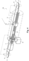
- the fourth embodiment shown in figure 4 is a variant of the third embodiment of the invention in which only the first cable 6 opposes a rotation of the nut 4 relative to the screw 2 in both directions of movement of the nut 4 relative to screw 2.
- the screw 2 extends along a first vertical axis Ox.
- the cable jack 100 comprises a first section 21.1 of a third cable 21 and a first section 22.1 of a fourth cable 22 which extend parallel to the first axis Ox between a first annular intermediate support 50 and the transverse face 32 of the tube 30.
- the first intermediate support 50 is connected to the nut 4 by the first and second cables 6 and 9.
- the first section 21.1 and the first section 22.1 extend on either side of the first axis Ox in a plane P1 comprising the first axis Ox.
- the plane P1 extends substantially orthogonally to a plane P2 comprising the first section 6.1 of the first cable 6 and the second section 9.1 of the second cable 9.
- the third cable 21 and the fourth cable 22 respectively have a first end 21.2 and 22.2 which are each connected to the first intermediate support 50: the third cable 21 and the fourth cable 22 are thus coupled to the nut 4.
- the third cable 21 and the fourth cable 22 are also functionally connected to the element to be moved 40 via the transverse face 32 of tube 30.
- a rotation of the screw 2 causes an identical rotation of the nut 4 due to the contact friction between the screw 2 and the nut 4.
- This movement puts tension on the first cable 6 and the second cable 9 as well as the third cable 21 and the fourth cable 22.
- the first cable 6 and the second cable 9 come to exert forces opposing a drive in rotation of the nut 4 by the screw 2, and these forces are transmitted to the third cable 21 and to the fourth cable 22.
- the cables 6, 9, 21, 22 then perform - in addition to their functions of transmitting displacement forces to the load 40 - an anti-rotation function so that a rotation of the screw 2 under the action of the motor 3 causes a movement of the nut 4 relative to the screw 2.
- the nut 4 moves axially under the effect of the rotation of the screw 2, without rotating around the first axis Ox.
- a lifting cylinder 100 without anti-rotation means other than the cables 6, 9, 21, 22 connected to the nut 4 is thus obtained.
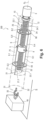
- the first cable 6 is crimped onto the first eyelet 5 and passes through the latter to have a first section 6.1 and a second section 6.4 extending parallel to the first axis Ox on either side of a plane P orthogonal to the first axis Ox comprising the first eyelet 5.
- the second cable 9 is crimped on the second eyelet 8 and passes through the latter to have a first section 9.1 and a second section 9.4 extending parallel to the first axis Ox on both sides on the other side of a plane P orthogonal to the first axis Ox comprising the second eyelet 8.
- the second end 6.3 of the first section 6.1 is connected to the first intermediate support 50 and the first end 6.2 is connected to a second intermediate support 60.
- the first section 21.1 of the third cable 21 and the first section 22.1 of the fourth cable 22 extend parallel to the first axis Ox between the first intermediate support 50 and a first transverse face 71 of a first cylindrical cage 70 extending around the nut 4.
- the first section 21.1 and the first section 22.1 extend on either side of the first axis Ox in a plane P1 comprising the first axis Ox.
- the plane P1 extends substantially orthogonally to a plane P2 comprising the first section 6.1 and the second section 9.1.
- a first section 23.1 of a fifth cable 23 and a first section 24.1 of a sixth cable 24 extend parallel to the first axis Ox between the second intermediate support 60 and a second transverse face 72 of the first cage 70 opposite the first transverse face 71.
- the first section 23.1 and the first section 24.1 extend on either side of the first axis Ox in the plane P1.
- the first and second sections 6.1 and 6.4 of the first cable 6, the first and second sections 9.1 and 9.4 of the second cable 9, the first section 21.1 of the third cable 21 and the first section 22.1 of the fourth cable 22, as well as the first section 23.1 of the fifth cable 23 and the first section 24.1 of the sixth cable 24 are preloaded.
- the first cage 70 is integral with the tube 30 mounted inside the cylinder 11 to form a slide connection according to methods known to those skilled in the art and not shown.
- the tube 30 comprises at its end 31 a transverse face 32 provided with a hook 33 to which is connected a load 40 to be moved.
- the first cable 6 and the second cable 9 are stretched - just like the cables 21, 22, 23 and 24 -, the first and second cables 6 and 9 as well as the cables 21, 22, 23 and 24 exert opposing forces to a rotational drive of the nut 4 by the screw 2 during a rotation of the motor 3 in both directions of movement of the nut 4 relative to the screw 2. They then perform - in addition to their transmission function displacement forces towards the load 40 - an anti-rotation function so that a rotation of the screw 2 under the action of the motor 3 causes a displacement of the nut 4 relative to the screw 2.
- the nut 4 moves axially as the screw rotates 2, without rotating around the first axis Ox, and this, in both directions of rotation of the screw 2.
- the cable jack 100 according to the sixth embodiment of the invention allows movement of the load 40 in two opposite directions .
- a cylinder 100 without anti-rotation means other than the first, second, third, fourth, fifth and sixth cables 6, 9, 21, 22, 23, 24 connected to the nut 4 is thus obtained.
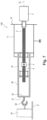
- the nut 4 is mounted in a bearing 90 integral with the frame 10 and which comprises two ball bearings 90.1 and 90.2.
- a motor 91 integral with the frame 12 comprises a pinion 92 which meshes with an external toothing 93 of the nut 4 to drive the latter in rotation.
- the screw 2 extends along a first horizontal axis Ox and comprises one end 80 secured to a disc 81.
- a first cable 6 and a second cable 9 extend parallel to the axis Ox on either side of that -this.
- the first section 6.1 of the first cable 6 extends from the disc 81 towards the load 40.
- a first section 9.1 of the second cable 9 extends from the disc 81 towards the load 40.
- a shift cylinder 100 devoid of anti-rotation means other than the first cable 6 and the second cable 9 connected to the screw 2 is thus obtained.
- the forces exerted by the first cable and, possibly the second cable, to oppose a rotation of the nut relative to the screw can be taken up by the load, the frame, an element linked to the frame or any other means.
- the low contact friction between the nut and the screw in comparison with the tension exerted on the cable by the load or other is sufficient to cause a translation of the nut without it being necessary to provide a recovery of the anti-rotation forces exerted by the cables.
- the first, second, third, fourth, fifth and sixth embodiments of the invention described in the context of a screw driven in rotation and moving a nut can be transposed to the case of a nut driven in rotation and moving a screw as described in the seventh embodiment of the invention.
Landscapes
- Engineering & Computer Science (AREA)
- General Engineering & Computer Science (AREA)
- Mechanical Engineering (AREA)
- Life Sciences & Earth Sciences (AREA)
- Geology (AREA)
- Structural Engineering (AREA)
- Transmission Devices (AREA)
Claims (14)
- Kabelzylinder (100), umfassend:- einen Rahmen (1);- eine Spindel (2), die am Rahmen montiert ist und sich entlang einer ersten Achse (Oy) erstreckt;- eine Mutter (4), die mit der Spindel (2) zusammenwirkt;- ein erstes Kabel (6), das an die Mutter oder an die Spindel (2) gekoppelt und dazu bestimmt ist, funktional mit einem zu verschiebenden Element verbunden zu werden;- einen Motor (3, 91), der ausgebildet ist, die Spindel (2) oder die Mutter (4) in Drehung anzutreiben;- wobei das erste Kabel (6) mindestens einen ersten Abschnitt (6.1) umfasst, der sich im Wesentlichen parallel zur ersten Achse (Ox) erstreckt, undwobei das erste Kabel (6) ausgebildet ist, Kräfte auszuüben, die einem Drehantrieb der Mutter (4) durch die Spindel (2) oder der Spindel (2) durch die Mutter (4) entgegenwirken, um Drehsicherungsmittel zu bilden, derart, dass eine Drehung der Spindel (2) oder der Mutter (4) unter der Wirkung des Motors (3, 91) eine relative Verschiebung der Mutter (4) und der Spindel (2) bewirkt, dadurch gekennzeichnet, dass er ein zweites Kabel (9) umfasst, das an die Mutter (4) oder an die Spindel (2) gekoppelt ist, wobei das zweite Kabel (9) ausgebildet ist, um Kräfte auszuüben, die einem Drehantrieb der Mutter (4) durch die Spindel (2) oder der Spindel (2) durch die Mutter (4) entgegenwirken, um Drehsicherungsmittel zu bilden, derart, dass eine Drehung der Spindel (2) oder der Mutter (4) unter der Wirkung des Motors (3, 91) eine relative Verschiebung der Mutter (4) und der Spindel (2) bewirkt,wobei sich ein Abschnitt (6.1) des ersten Kabels (6) und ein Abschnitt (93.1) des zweiten Kabels (9) zu beiden Seiten der ersten Achse (Ox) erstrecken.
- Zylinder (100) nach Anspruch 1, bei dem das erste Kabel (6) und/oder das zweite Kabel (9) an die Mutter (4) oder an die Spindel (2) gekoppelt ist, um Kräfte auszuüben, die einem Drehantrieb der Mutter (4) durch die Spindel (2) oder der Spindel (2) durch die Mutter (4) in beiden Richtungen einer relativen Verschiebung der Mutter (4) und der Spindel (2) entgegenwirken.
- Zylinder (100) nach einem der vorhergehenden Ansprüche, umfassend ein drittes Kabel (21), das an die Mutter (4) oder an die Spindel (2) gekoppelt ist, wobei das dritte Kabel (21) funktional mit dem zu verschiebenden Element (40) verbunden ist.
- Zylinder (100) nach Anspruch 3, umfassend ein viertes Kabel (22), das an die Mutter (4) oder an die Spindel (2) gekoppelt ist, wobei das vierte Kabel (22) funktional mit dem zu verschiebenden Element (40) verbunden ist.
- Zylinder (100) nach Anspruch 4, bei dem sich ein Abschnitt (21.1) des dritten Kabels (21) und ein Abschnitt (22.1) des vierten Kabels (22) zu beiden Seiten der ersten Achse (Ox) erstrecken.
- Zylinder (100) nach einem der Ansprüche 3 bis 5, bei dem sich das erste (6) und/oder das zweite Kabel (9) zwischen der Mutter (4) oder der Spindel (2) und einem ersten Zwischenträger (50) erstrecken, und bei dem das dritte Kabel (21) ein erstes Ende (21.2) hat, das mit dem ersten Zwischenträger (50) verbunden ist, sowie ein zweites Ende, das funktional mit dem zu verschiebenden Element (40) verbunden ist.
- Zylinder (100) nach Anspruch 6, bei dem das vierte Kabel (22) ein erstes Ende (22.1) hat, das mit dem ersten Zwischenträger (50) verbunden ist, und ein zweites Ende, das dazu bestimmt ist, funktional mit dem zu verschiebenden Element (40) verbunden zu werden.
- Zylinder (100) nach einem der Ansprüche 6 oder 7, umfassend ein fünftes Kabel (23), das an die Mutter (4) oder an die Spindel (2) gekoppelt ist, wobei das fünfte Kabel (23) funktional mit dem zu verschiebenden Element (40) verbunden ist.
- Zylinder (100) nach Anspruch 8, umfassend ein sechstes Kabel (24), das an die Mutter (4) oder die Spindel (2) gekoppelt ist, wobei das sechste Kabel (24) funktional mit dem zu verschiebenden Element (40) verbunden ist.
- Zylinder (100) nach Anspruch 9, bei dem sich ein Abschnitt (23.1) des fünften Kabels (23) und ein Abschnitt (24.1) des sechsten Kabels (24) zu beiden Seiten der ersten Achse (Ox) erstrecken.
- Zylinder (100) nach einem der Ansprüche 8 bis 10, bei dem sich das erste (6) und das zweite Kabel (9) ebenso zwischen der Mutter (4) oder der Spindel (2) und einem zweiten Zwischenträger (60) erstrecken und bei dem das fünfte Kabel (23) mit dem zweiten Zwischenträger (60) verbunden ist.
- Zylinder (100) nach Anspruch 11, bei dem das sechste Kabel (24) mit dem zweiten Zwischenträger (60) verbunden ist.
- Zylinder (100) nach einem der vorhergehenden Ansprüche, bei dem ein beliebiges der Kabel (6, 9, 21, 22, 23, 24) vorgespannt ist.
- Zylinder (100) nach einem der vorhergehenden Ansprüche, bei dem die Spindel (2) eine Kugelumlaufspindel ist.
Applications Claiming Priority (2)
| Application Number | Priority Date | Filing Date | Title |
|---|---|---|---|
| FR1757618A FR3070062B1 (fr) | 2017-08-09 | 2017-08-09 | Anti-rotation a cables |
| PCT/EP2018/069691 WO2019029976A1 (fr) | 2017-08-09 | 2018-07-19 | Anti-rotation a cables |
Publications (2)
| Publication Number | Publication Date |
|---|---|
| EP3665403A1 EP3665403A1 (de) | 2020-06-17 |
| EP3665403B1 true EP3665403B1 (de) | 2023-06-28 |
Family
ID=60182719
Family Applications (1)
| Application Number | Title | Priority Date | Filing Date |
|---|---|---|---|
| EP18746128.0A Active EP3665403B1 (de) | 2017-08-09 | 2018-07-19 | Verdrehsicherung mit kabeln |
Country Status (4)
| Country | Link |
|---|---|
| US (1) | US11407622B2 (de) |
| EP (1) | EP3665403B1 (de) |
| FR (1) | FR3070062B1 (de) |
| WO (1) | WO2019029976A1 (de) |
Families Citing this family (9)
| Publication number | Priority date | Publication date | Assignee | Title |
|---|---|---|---|---|
| FR3070062B1 (fr) * | 2017-08-09 | 2019-08-23 | Commissariat A L`Energie Atomique Et Aux Energies Alternatives | Anti-rotation a cables |
| CN110546869B (zh) * | 2018-10-17 | 2021-05-04 | 炼马机电(东莞)有限公司 | 驱动块、线性驱动器及可调用具 |
| US11815417B2 (en) * | 2020-02-26 | 2023-11-14 | Commissariat A L'energie Atomique Et Aux Energies Alternatives | Force sensor for cable actuator |
| FR3110947B1 (fr) | 2020-06-02 | 2022-09-09 | Commissariat Energie Atomique | Capteur d’effort pour actionneur à câble |
| FR3115084B1 (fr) * | 2020-10-13 | 2022-11-25 | Commissariat Energie Atomique | Actionneur à câble à compacité améliorée |
| FR3130005B1 (fr) | 2021-12-03 | 2023-11-24 | Commissariat Energie Atomique | Actionneur à câble à sensibilité en effort améliorée |
| FR3135768B1 (fr) | 2022-05-18 | 2024-05-03 | Commissariat Energie Atomique | Vérin à câbles à boucles asymétriques |
| FR3137146B1 (fr) | 2022-06-23 | 2024-07-12 | Commissariat Energie Atomique | Actionneur à câble à compacité améliorée |
| FR3143701B1 (fr) * | 2022-12-16 | 2024-11-29 | Commissariat Energie Atomique | Actionneur à câble compact |
Family Cites Families (9)
| Publication number | Priority date | Publication date | Assignee | Title |
|---|---|---|---|---|
| DE10313739A1 (de) * | 2002-04-06 | 2003-10-16 | Luk Lamellen & Kupplungsbau | Kupplungsbetätigungen |
| US8015889B2 (en) * | 2005-11-15 | 2011-09-13 | Honeywell International Inc. | Ballscrew with an integral high-efficiency thrust bearing |
| US9500224B2 (en) * | 2011-04-15 | 2016-11-22 | Thomson Industries Inc. | Linear motion guided screw assembly |
| FR3002607B1 (fr) * | 2013-02-22 | 2016-07-08 | Commissariat A L`Energie Atomique Et Aux Energies Alternatives | Verin a cables tolerant aux desalignements |
| US20150059503A1 (en) * | 2013-08-29 | 2015-03-05 | Parker-Hannifin Corporation | Thrust cylinder with offset drive screw |
| FR3018327B1 (fr) * | 2014-03-10 | 2016-03-25 | Commissariat Energie Atomique | Verin a cable equipe d’un dispositif d’anti-rotation a element longiligne flexible mais rigide en torsion |
| EP3212968B1 (de) * | 2014-10-31 | 2020-12-02 | D-Box Technologies Inc. | Linearantrieb für einen bewegungssimulator |
| FR3070062B1 (fr) * | 2017-08-09 | 2019-08-23 | Commissariat A L`Energie Atomique Et Aux Energies Alternatives | Anti-rotation a cables |
| US11815417B2 (en) * | 2020-02-26 | 2023-11-14 | Commissariat A L'energie Atomique Et Aux Energies Alternatives | Force sensor for cable actuator |
-
2017
- 2017-08-09 FR FR1757618A patent/FR3070062B1/fr not_active Expired - Fee Related
-
2018
- 2018-07-19 WO PCT/EP2018/069691 patent/WO2019029976A1/fr not_active Ceased
- 2018-07-19 US US16/636,453 patent/US11407622B2/en active Active
- 2018-07-19 EP EP18746128.0A patent/EP3665403B1/de active Active
Also Published As
| Publication number | Publication date |
|---|---|
| FR3070062B1 (fr) | 2019-08-23 |
| EP3665403A1 (de) | 2020-06-17 |
| WO2019029976A1 (fr) | 2019-02-14 |
| US20200172383A1 (en) | 2020-06-04 |
| FR3070062A1 (fr) | 2019-02-15 |
| US11407622B2 (en) | 2022-08-09 |
Similar Documents
| Publication | Publication Date | Title |
|---|---|---|
| EP3665403B1 (de) | Verdrehsicherung mit kabeln | |
| EP1048890B1 (de) | Flexibler Drehwinkelbegrenzungsanschlag, Gelenksystem mit solch einem Anschlag und medizinische Ausrüstung mit solch einem Gelenksystem | |
| EP2981739A1 (de) | Kabelantrieb für erhöhten spielraum einer verbindung | |
| FR2665935A1 (fr) | Appareil a arbre monte dans un palier a charge variable, et procede d'application d'une charge a un palier. | |
| EP0658697B1 (de) | Entkuppelbarer Freilauf | |
| FR2561616A1 (fr) | Dispositif d'actionnement a blocage automatique et ensemble d'actionnement comprenant deux dispositifs de ce type, en particulier pour l'aviation | |
| FR2900591A1 (fr) | Structure de robot de type scara, et robot correspondant | |
| FR2532699A1 (fr) | Dispositif de reduction du jeu d'extremite axial de l'arbre d'induit d'un moteur | |
| EP3903015B1 (de) | Getriebe für einen kabelzylinder mit versetzter mutterverankerung | |
| EP4191094B1 (de) | Kabelaktuator mit verbesserter kraftempfindlichkeit | |
| FR3115084A1 (fr) | Actionneur à câble à compacité améliorée | |
| EP0593338B1 (de) | Einrichtung zur Zusammensetzung von zwei Teilen in einer Verschraubungsstation | |
| EP2148102B1 (de) | Axiallastunempfindliches Notlager | |
| FR2792427A1 (fr) | Dispositif de rappel au point neutre, en particulier pour volant sans axe, et volant sans axe comportant un tel dispositif | |
| FR2675861A1 (fr) | Roulement perfectionne integrant un capteur de vitesse. | |
| EP3385573B1 (de) | Rollenwalzen für den drehantrieb eines luftfahrzeugrads | |
| WO2021244843A1 (fr) | Capteur d'effort pour actionneur a câble | |
| EP3660353B1 (de) | Kraftsensor für stellglied mit kabel und verfahren | |
| EP3839604B1 (de) | Verbesserte exzentrische scan-vorrichtung | |
| EP4662425A1 (de) | Schrauben-mutter-getriebesystem | |
| FR2610682A1 (fr) | Joint de transmission tripode coulissant et arbre de transmission comportant deux joints de ce type | |
| FR2941760A1 (fr) | Verin a cable monopalier | |
| EP1791242B1 (de) | Linearantrieb | |
| EP4484796A1 (de) | Antriebseinheit für eine mobilitätsvorrichtung, insbesondere eines fahrzeugs | |
| WO2024052603A1 (fr) | Module de positionnement angulaire pour banc optique |
Legal Events
| Date | Code | Title | Description |
|---|---|---|---|
| STAA | Information on the status of an ep patent application or granted ep patent |
Free format text: STATUS: UNKNOWN |
|
| STAA | Information on the status of an ep patent application or granted ep patent |
Free format text: STATUS: THE INTERNATIONAL PUBLICATION HAS BEEN MADE |
|
| PUAI | Public reference made under article 153(3) epc to a published international application that has entered the european phase |
Free format text: ORIGINAL CODE: 0009012 |
|
| STAA | Information on the status of an ep patent application or granted ep patent |
Free format text: STATUS: REQUEST FOR EXAMINATION WAS MADE |
|
| 17P | Request for examination filed |
Effective date: 20200130 |
|
| AK | Designated contracting states |
Kind code of ref document: A1 Designated state(s): AL AT BE BG CH CY CZ DE DK EE ES FI FR GB GR HR HU IE IS IT LI LT LU LV MC MK MT NL NO PL PT RO RS SE SI SK SM TR |
|
| AX | Request for extension of the european patent |
Extension state: BA ME |
|
| DAV | Request for validation of the european patent (deleted) | ||
| DAX | Request for extension of the european patent (deleted) | ||
| GRAP | Despatch of communication of intention to grant a patent |
Free format text: ORIGINAL CODE: EPIDOSNIGR1 |
|
| STAA | Information on the status of an ep patent application or granted ep patent |
Free format text: STATUS: GRANT OF PATENT IS INTENDED |
|
| INTG | Intention to grant announced |
Effective date: 20230210 |
|
| GRAS | Grant fee paid |
Free format text: ORIGINAL CODE: EPIDOSNIGR3 |
|
| GRAA | (expected) grant |
Free format text: ORIGINAL CODE: 0009210 |
|
| STAA | Information on the status of an ep patent application or granted ep patent |
Free format text: STATUS: THE PATENT HAS BEEN GRANTED |
|
| AK | Designated contracting states |
Kind code of ref document: B1 Designated state(s): AL AT BE BG CH CY CZ DE DK EE ES FI FR GB GR HR HU IE IS IT LI LT LU LV MC MK MT NL NO PL PT RO RS SE SI SK SM TR |
|
| REG | Reference to a national code |
Ref country code: CH Ref legal event code: EP |
|
| REG | Reference to a national code |
Ref country code: AT Ref legal event code: REF Ref document number: 1582935 Country of ref document: AT Kind code of ref document: T Effective date: 20230715 |
|
| REG | Reference to a national code |
Ref country code: IE Ref legal event code: FG4D Free format text: LANGUAGE OF EP DOCUMENT: FRENCH |
|
| REG | Reference to a national code |
Ref country code: DE Ref legal event code: R096 Ref document number: 602018052434 Country of ref document: DE |
|
| REG | Reference to a national code |
Ref country code: LT Ref legal event code: MG9D |
|
| PG25 | Lapsed in a contracting state [announced via postgrant information from national office to epo] |
Ref country code: SE Free format text: LAPSE BECAUSE OF FAILURE TO SUBMIT A TRANSLATION OF THE DESCRIPTION OR TO PAY THE FEE WITHIN THE PRESCRIBED TIME-LIMIT Effective date: 20230628 Ref country code: NO Free format text: LAPSE BECAUSE OF FAILURE TO SUBMIT A TRANSLATION OF THE DESCRIPTION OR TO PAY THE FEE WITHIN THE PRESCRIBED TIME-LIMIT Effective date: 20230928 |
|
| REG | Reference to a national code |
Ref country code: AT Ref legal event code: MK05 Ref document number: 1582935 Country of ref document: AT Kind code of ref document: T Effective date: 20230628 |
|
| PG25 | Lapsed in a contracting state [announced via postgrant information from national office to epo] |
Ref country code: RS Free format text: LAPSE BECAUSE OF FAILURE TO SUBMIT A TRANSLATION OF THE DESCRIPTION OR TO PAY THE FEE WITHIN THE PRESCRIBED TIME-LIMIT Effective date: 20230628 Ref country code: NL Free format text: LAPSE BECAUSE OF FAILURE TO SUBMIT A TRANSLATION OF THE DESCRIPTION OR TO PAY THE FEE WITHIN THE PRESCRIBED TIME-LIMIT Effective date: 20230628 Ref country code: LV Free format text: LAPSE BECAUSE OF FAILURE TO SUBMIT A TRANSLATION OF THE DESCRIPTION OR TO PAY THE FEE WITHIN THE PRESCRIBED TIME-LIMIT Effective date: 20230628 Ref country code: LT Free format text: LAPSE BECAUSE OF FAILURE TO SUBMIT A TRANSLATION OF THE DESCRIPTION OR TO PAY THE FEE WITHIN THE PRESCRIBED TIME-LIMIT Effective date: 20230628 Ref country code: HR Free format text: LAPSE BECAUSE OF FAILURE TO SUBMIT A TRANSLATION OF THE DESCRIPTION OR TO PAY THE FEE WITHIN THE PRESCRIBED TIME-LIMIT Effective date: 20230628 Ref country code: GR Free format text: LAPSE BECAUSE OF FAILURE TO SUBMIT A TRANSLATION OF THE DESCRIPTION OR TO PAY THE FEE WITHIN THE PRESCRIBED TIME-LIMIT Effective date: 20230929 |
|
| PG25 | Lapsed in a contracting state [announced via postgrant information from national office to epo] |
Ref country code: FI Free format text: LAPSE BECAUSE OF FAILURE TO SUBMIT A TRANSLATION OF THE DESCRIPTION OR TO PAY THE FEE WITHIN THE PRESCRIBED TIME-LIMIT Effective date: 20230628 |
|
| PG25 | Lapsed in a contracting state [announced via postgrant information from national office to epo] |
Ref country code: SK Free format text: LAPSE BECAUSE OF FAILURE TO SUBMIT A TRANSLATION OF THE DESCRIPTION OR TO PAY THE FEE WITHIN THE PRESCRIBED TIME-LIMIT Effective date: 20230628 |
|
| PG25 | Lapsed in a contracting state [announced via postgrant information from national office to epo] |
Ref country code: ES Free format text: LAPSE BECAUSE OF FAILURE TO SUBMIT A TRANSLATION OF THE DESCRIPTION OR TO PAY THE FEE WITHIN THE PRESCRIBED TIME-LIMIT Effective date: 20230628 |
|
| PG25 | Lapsed in a contracting state [announced via postgrant information from national office to epo] |
Ref country code: IS Free format text: LAPSE BECAUSE OF FAILURE TO SUBMIT A TRANSLATION OF THE DESCRIPTION OR TO PAY THE FEE WITHIN THE PRESCRIBED TIME-LIMIT Effective date: 20231028 |
|
| PG25 | Lapsed in a contracting state [announced via postgrant information from national office to epo] |
Ref country code: SM Free format text: LAPSE BECAUSE OF FAILURE TO SUBMIT A TRANSLATION OF THE DESCRIPTION OR TO PAY THE FEE WITHIN THE PRESCRIBED TIME-LIMIT Effective date: 20230628 Ref country code: SK Free format text: LAPSE BECAUSE OF FAILURE TO SUBMIT A TRANSLATION OF THE DESCRIPTION OR TO PAY THE FEE WITHIN THE PRESCRIBED TIME-LIMIT Effective date: 20230628 Ref country code: RO Free format text: LAPSE BECAUSE OF FAILURE TO SUBMIT A TRANSLATION OF THE DESCRIPTION OR TO PAY THE FEE WITHIN THE PRESCRIBED TIME-LIMIT Effective date: 20230628 Ref country code: PT Free format text: LAPSE BECAUSE OF FAILURE TO SUBMIT A TRANSLATION OF THE DESCRIPTION OR TO PAY THE FEE WITHIN THE PRESCRIBED TIME-LIMIT Effective date: 20231030 Ref country code: IS Free format text: LAPSE BECAUSE OF FAILURE TO SUBMIT A TRANSLATION OF THE DESCRIPTION OR TO PAY THE FEE WITHIN THE PRESCRIBED TIME-LIMIT Effective date: 20231028 Ref country code: ES Free format text: LAPSE BECAUSE OF FAILURE TO SUBMIT A TRANSLATION OF THE DESCRIPTION OR TO PAY THE FEE WITHIN THE PRESCRIBED TIME-LIMIT Effective date: 20230628 Ref country code: EE Free format text: LAPSE BECAUSE OF FAILURE TO SUBMIT A TRANSLATION OF THE DESCRIPTION OR TO PAY THE FEE WITHIN THE PRESCRIBED TIME-LIMIT Effective date: 20230628 Ref country code: CZ Free format text: LAPSE BECAUSE OF FAILURE TO SUBMIT A TRANSLATION OF THE DESCRIPTION OR TO PAY THE FEE WITHIN THE PRESCRIBED TIME-LIMIT Effective date: 20230628 Ref country code: AT Free format text: LAPSE BECAUSE OF FAILURE TO SUBMIT A TRANSLATION OF THE DESCRIPTION OR TO PAY THE FEE WITHIN THE PRESCRIBED TIME-LIMIT Effective date: 20230628 |
|
| PG25 | Lapsed in a contracting state [announced via postgrant information from national office to epo] |
Ref country code: PL Free format text: LAPSE BECAUSE OF FAILURE TO SUBMIT A TRANSLATION OF THE DESCRIPTION OR TO PAY THE FEE WITHIN THE PRESCRIBED TIME-LIMIT Effective date: 20230628 |
|
| REG | Reference to a national code |
Ref country code: CH Ref legal event code: PL |
|
| PG25 | Lapsed in a contracting state [announced via postgrant information from national office to epo] |
Ref country code: MC Free format text: LAPSE BECAUSE OF FAILURE TO SUBMIT A TRANSLATION OF THE DESCRIPTION OR TO PAY THE FEE WITHIN THE PRESCRIBED TIME-LIMIT Effective date: 20230628 |
|
| REG | Reference to a national code |
Ref country code: BE Ref legal event code: MM Effective date: 20230731 |
|
| PG25 | Lapsed in a contracting state [announced via postgrant information from national office to epo] |
Ref country code: LU Free format text: LAPSE BECAUSE OF NON-PAYMENT OF DUE FEES Effective date: 20230719 |
|
| PG25 | Lapsed in a contracting state [announced via postgrant information from national office to epo] |
Ref country code: MC Free format text: LAPSE BECAUSE OF FAILURE TO SUBMIT A TRANSLATION OF THE DESCRIPTION OR TO PAY THE FEE WITHIN THE PRESCRIBED TIME-LIMIT Effective date: 20230628 Ref country code: LU Free format text: LAPSE BECAUSE OF NON-PAYMENT OF DUE FEES Effective date: 20230719 |
|
| REG | Reference to a national code |
Ref country code: DE Ref legal event code: R097 Ref document number: 602018052434 Country of ref document: DE |
|
| REG | Reference to a national code |
Ref country code: IE Ref legal event code: MM4A |
|
| PG25 | Lapsed in a contracting state [announced via postgrant information from national office to epo] |
Ref country code: DK Free format text: LAPSE BECAUSE OF FAILURE TO SUBMIT A TRANSLATION OF THE DESCRIPTION OR TO PAY THE FEE WITHIN THE PRESCRIBED TIME-LIMIT Effective date: 20230628 Ref country code: CH Free format text: LAPSE BECAUSE OF NON-PAYMENT OF DUE FEES Effective date: 20230731 |
|
| PLBE | No opposition filed within time limit |
Free format text: ORIGINAL CODE: 0009261 |
|
| STAA | Information on the status of an ep patent application or granted ep patent |
Free format text: STATUS: NO OPPOSITION FILED WITHIN TIME LIMIT |
|
| PG25 | Lapsed in a contracting state [announced via postgrant information from national office to epo] |
Ref country code: IT Free format text: LAPSE BECAUSE OF FAILURE TO SUBMIT A TRANSLATION OF THE DESCRIPTION OR TO PAY THE FEE WITHIN THE PRESCRIBED TIME-LIMIT Effective date: 20230628 Ref country code: BE Free format text: LAPSE BECAUSE OF NON-PAYMENT OF DUE FEES Effective date: 20230731 |
|
| 26N | No opposition filed |
Effective date: 20240402 |
|
| PG25 | Lapsed in a contracting state [announced via postgrant information from national office to epo] |
Ref country code: IE Free format text: LAPSE BECAUSE OF NON-PAYMENT OF DUE FEES Effective date: 20230719 |
|
| PG25 | Lapsed in a contracting state [announced via postgrant information from national office to epo] |
Ref country code: IE Free format text: LAPSE BECAUSE OF NON-PAYMENT OF DUE FEES Effective date: 20230719 Ref country code: SI Free format text: LAPSE BECAUSE OF FAILURE TO SUBMIT A TRANSLATION OF THE DESCRIPTION OR TO PAY THE FEE WITHIN THE PRESCRIBED TIME-LIMIT Effective date: 20230628 |
|
| PG25 | Lapsed in a contracting state [announced via postgrant information from national office to epo] |
Ref country code: BG Free format text: LAPSE BECAUSE OF FAILURE TO SUBMIT A TRANSLATION OF THE DESCRIPTION OR TO PAY THE FEE WITHIN THE PRESCRIBED TIME-LIMIT Effective date: 20230628 |
|
| PG25 | Lapsed in a contracting state [announced via postgrant information from national office to epo] |
Ref country code: BG Free format text: LAPSE BECAUSE OF FAILURE TO SUBMIT A TRANSLATION OF THE DESCRIPTION OR TO PAY THE FEE WITHIN THE PRESCRIBED TIME-LIMIT Effective date: 20230628 |
|
| PG25 | Lapsed in a contracting state [announced via postgrant information from national office to epo] |
Ref country code: CY Free format text: LAPSE BECAUSE OF FAILURE TO SUBMIT A TRANSLATION OF THE DESCRIPTION OR TO PAY THE FEE WITHIN THE PRESCRIBED TIME-LIMIT; INVALID AB INITIO Effective date: 20180719 |
|
| PG25 | Lapsed in a contracting state [announced via postgrant information from national office to epo] |
Ref country code: HU Free format text: LAPSE BECAUSE OF FAILURE TO SUBMIT A TRANSLATION OF THE DESCRIPTION OR TO PAY THE FEE WITHIN THE PRESCRIBED TIME-LIMIT; INVALID AB INITIO Effective date: 20180719 |
|
| PGFP | Annual fee paid to national office [announced via postgrant information from national office to epo] |
Ref country code: DE Payment date: 20250722 Year of fee payment: 8 |
|
| PGFP | Annual fee paid to national office [announced via postgrant information from national office to epo] |
Ref country code: GB Payment date: 20250722 Year of fee payment: 8 |
|
| PGFP | Annual fee paid to national office [announced via postgrant information from national office to epo] |
Ref country code: FR Payment date: 20250725 Year of fee payment: 8 |
|
| PG25 | Lapsed in a contracting state [announced via postgrant information from national office to epo] |
Ref country code: TR Free format text: LAPSE BECAUSE OF FAILURE TO SUBMIT A TRANSLATION OF THE DESCRIPTION OR TO PAY THE FEE WITHIN THE PRESCRIBED TIME-LIMIT Effective date: 20230628 |