EP4191094B1 - Kabelaktuator mit verbesserter kraftempfindlichkeit - Google Patents
Kabelaktuator mit verbesserter kraftempfindlichkeit Download PDFInfo
- Publication number
- EP4191094B1 EP4191094B1 EP22209679.4A EP22209679A EP4191094B1 EP 4191094 B1 EP4191094 B1 EP 4191094B1 EP 22209679 A EP22209679 A EP 22209679A EP 4191094 B1 EP4191094 B1 EP 4191094B1
- Authority
- EP
- European Patent Office
- Prior art keywords
- nut
- cable
- screw
- actuator
- thread
- Prior art date
- Legal status (The legal status is an assumption and is not a legal conclusion. Google has not performed a legal analysis and makes no representation as to the accuracy of the status listed.)
- Active
Links
Images



Classifications
-
- F—MECHANICAL ENGINEERING; LIGHTING; HEATING; WEAPONS; BLASTING
- F16—ENGINEERING ELEMENTS AND UNITS; GENERAL MEASURES FOR PRODUCING AND MAINTAINING EFFECTIVE FUNCTIONING OF MACHINES OR INSTALLATIONS; THERMAL INSULATION IN GENERAL
- F16H—GEARING
- F16H25/00—Gearings comprising primarily only cams, cam-followers and screw-and-nut mechanisms
- F16H25/18—Gearings comprising primarily only cams, cam-followers and screw-and-nut mechanisms for conveying or interconverting oscillating or reciprocating motions
- F16H25/20—Screw mechanisms
-
- F—MECHANICAL ENGINEERING; LIGHTING; HEATING; WEAPONS; BLASTING
- F16—ENGINEERING ELEMENTS AND UNITS; GENERAL MEASURES FOR PRODUCING AND MAINTAINING EFFECTIVE FUNCTIONING OF MACHINES OR INSTALLATIONS; THERMAL INSULATION IN GENERAL
- F16H—GEARING
- F16H19/00—Gearings comprising essentially only toothed gears or friction members and not capable of conveying indefinitely-continuing rotary motion
- F16H19/02—Gearings comprising essentially only toothed gears or friction members and not capable of conveying indefinitely-continuing rotary motion for interconverting rotary or oscillating motion and reciprocating motion
- F16H19/06—Gearings comprising essentially only toothed gears or friction members and not capable of conveying indefinitely-continuing rotary motion for interconverting rotary or oscillating motion and reciprocating motion comprising flexible members, e.g. an endless flexible member
- F16H19/0622—Gearings comprising essentially only toothed gears or friction members and not capable of conveying indefinitely-continuing rotary motion for interconverting rotary or oscillating motion and reciprocating motion comprising flexible members, e.g. an endless flexible member for converting reciprocating movement into oscillating movement and vice versa, the reciprocating movement is perpendicular to the axis of oscillation
-
- F—MECHANICAL ENGINEERING; LIGHTING; HEATING; WEAPONS; BLASTING
- F16—ENGINEERING ELEMENTS AND UNITS; GENERAL MEASURES FOR PRODUCING AND MAINTAINING EFFECTIVE FUNCTIONING OF MACHINES OR INSTALLATIONS; THERMAL INSULATION IN GENERAL
- F16H—GEARING
- F16H25/00—Gearings comprising primarily only cams, cam-followers and screw-and-nut mechanisms
- F16H25/18—Gearings comprising primarily only cams, cam-followers and screw-and-nut mechanisms for conveying or interconverting oscillating or reciprocating motions
- F16H25/20—Screw mechanisms
- F16H25/2015—Means specially adapted for stopping actuators in the end position; Position sensing means
-
- F—MECHANICAL ENGINEERING; LIGHTING; HEATING; WEAPONS; BLASTING
- F16—ENGINEERING ELEMENTS AND UNITS; GENERAL MEASURES FOR PRODUCING AND MAINTAINING EFFECTIVE FUNCTIONING OF MACHINES OR INSTALLATIONS; THERMAL INSULATION IN GENERAL
- F16H—GEARING
- F16H25/00—Gearings comprising primarily only cams, cam-followers and screw-and-nut mechanisms
- F16H25/18—Gearings comprising primarily only cams, cam-followers and screw-and-nut mechanisms for conveying or interconverting oscillating or reciprocating motions
- F16H25/20—Screw mechanisms
- F16H25/24—Elements essential to such mechanisms, e.g. screws, nuts
-
- F—MECHANICAL ENGINEERING; LIGHTING; HEATING; WEAPONS; BLASTING
- F16—ENGINEERING ELEMENTS AND UNITS; GENERAL MEASURES FOR PRODUCING AND MAINTAINING EFFECTIVE FUNCTIONING OF MACHINES OR INSTALLATIONS; THERMAL INSULATION IN GENERAL
- F16H—GEARING
- F16H19/00—Gearings comprising essentially only toothed gears or friction members and not capable of conveying indefinitely-continuing rotary motion
- F16H19/02—Gearings comprising essentially only toothed gears or friction members and not capable of conveying indefinitely-continuing rotary motion for interconverting rotary or oscillating motion and reciprocating motion
- F16H19/06—Gearings comprising essentially only toothed gears or friction members and not capable of conveying indefinitely-continuing rotary motion for interconverting rotary or oscillating motion and reciprocating motion comprising flexible members, e.g. an endless flexible member
- F16H2019/0681—Gearings comprising essentially only toothed gears or friction members and not capable of conveying indefinitely-continuing rotary motion for interconverting rotary or oscillating motion and reciprocating motion comprising flexible members, e.g. an endless flexible member the flexible member forming a closed loop
- F16H2019/0686—Gearings comprising essentially only toothed gears or friction members and not capable of conveying indefinitely-continuing rotary motion for interconverting rotary or oscillating motion and reciprocating motion comprising flexible members, e.g. an endless flexible member the flexible member forming a closed loop the flexible member being directly driven by a pulley or chain wheel
-
- F—MECHANICAL ENGINEERING; LIGHTING; HEATING; WEAPONS; BLASTING
- F16—ENGINEERING ELEMENTS AND UNITS; GENERAL MEASURES FOR PRODUCING AND MAINTAINING EFFECTIVE FUNCTIONING OF MACHINES OR INSTALLATIONS; THERMAL INSULATION IN GENERAL
- F16H—GEARING
- F16H25/00—Gearings comprising primarily only cams, cam-followers and screw-and-nut mechanisms
- F16H25/18—Gearings comprising primarily only cams, cam-followers and screw-and-nut mechanisms for conveying or interconverting oscillating or reciprocating motions
- F16H25/20—Screw mechanisms
- F16H2025/204—Axial sliding means, i.e. for rotary support and axial guiding of nut or screw shaft
-
- F—MECHANICAL ENGINEERING; LIGHTING; HEATING; WEAPONS; BLASTING
- F16—ENGINEERING ELEMENTS AND UNITS; GENERAL MEASURES FOR PRODUCING AND MAINTAINING EFFECTIVE FUNCTIONING OF MACHINES OR INSTALLATIONS; THERMAL INSULATION IN GENERAL
- F16H—GEARING
- F16H25/00—Gearings comprising primarily only cams, cam-followers and screw-and-nut mechanisms
- F16H25/18—Gearings comprising primarily only cams, cam-followers and screw-and-nut mechanisms for conveying or interconverting oscillating or reciprocating motions
- F16H25/20—Screw mechanisms
- F16H2025/2062—Arrangements for driving the actuator
- F16H2025/2075—Coaxial drive motors
Definitions
- the invention relates to a cable actuator comprising a screw/nut assembly, the nut of which is movable in translation and attached by a cable to an element to be moved and which is provided with a force sensor.
- the invention relates more particularly to cable actuators, the cable of which performs an anti-rotation function of the nut relative to the screw.
- Cable actuators comprising a screw mounted on a frame and a nut cooperating with the screw.
- the nut is associated with anti-rotation means so that a relative rotation of the screw and the nut causes an axial displacement of the nut.
- One or more cables associated with the nut are connected to an output of the actuator which can be rotary (when the cables are connected to pulleys) or linear (when the cables are connected directly to the load to be handled).
- the object of the invention is to improve the precision and manufacturing and/or maintenance costs of a cable actuator.
- a cable actuator is provided as described in claim 1.
- the distance sensor is arranged such that the wire undergoes a change of curvature at a first point located in a first plane orthogonal to the first axis, the plane being located at a first distance from the first extreme point of between thirty and seventy percent of the stroke.
- the first distance is between forty percent and sixty percent of the race, preferably fifty percent.
- the first point is located at a second non-zero distance from a straight line connecting the first axis and the connection point.
- the change in curvature of the wire is carried out by a drum of the winder.
- the distance sensor comprises a drum-type wire winder, and the change in curvature of the wire is achieved by the drum of the winder.
- the wire can make a plurality of turns on a drum of the reel.
- the wired distance sensor includes a linear displacement sensor.
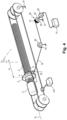
- the actuator of the invention comprises a frame 10, here a portion of straight cylinder 11 comprising a base 12 in the center of which a bearing 13 accommodates a screw 2 rotating around a first horizontal axis Ox.
- the screw 2 is a ball screw of pitch p 2 which is driven in rotation by an electric motor 3 comprising a first rotary encoder 3.1.
- a nut 4 cooperates with the screw 2 and comprises a first eyelet 5 projecting radially from the nut 4.
- a first cable 6 extends parallel to the first axis Ox and comprises a first section 6.1 held at its first end 6.2 in the first eyelet 5 by a first crimp 7.1.
- the second end 6.3 of the first section 6.1 of the first cable 6 is crimped onto a first pulley 14 secured to a first shaft 16 rotatably mounted on the frame 10 along an axis perpendicular to the first axis Ox.
- the first cable 6 also comprises a second section 6.4 of first cable 6 extending parallel to the first axis Ox on either side of a plane P orthogonal to the first axis Ox comprising the first eyelet 5 and which is held at its first end 6.5 in the first eyelet 5 by the first crimp 7.1.
- the second end 6.6 of the second section 6.4 of the first cable 6 is crimped onto a second pulley 15 secured to a second shaft 17 mounted to rotate on the chassis 10 along an axis perpendicular to the first axis Ox.
- the nut 4 comprises a second eyelet 8 projecting radially from the nut 4 so as to be diametrically opposite the first eyelet 5.
- a second cable 9 extends parallel to the first axis Ox and comprises a first section 9.1 of second cable 9 held at its first end 9.2 in the second eyelet 8 by a second crimp 7.2.
- the second end 9.3 of the first section 9.1 of the second cable 9 is connected to a third pulley 18 secured to the first shaft 16 rotatably mounted on the chassis 10 along an axis perpendicular to the first axis Ox.
- the second cable 9 also comprises a second section 9.4 extending parallel to the first axis Ox on the part and on the other side of a plane P orthogonal to the first axis Ox comprising the second eyelet 8 and which is held at its first end 9.5 in the second eyelet 8 by the second crimp 7.2.
- the second end 9.6 of the second section 9.4 of the second cable 9 is crimped onto a fourth pulley 19 secured to the second shaft 17 rotatably mounted on the chassis 10 along an axis perpendicular to the first axis Ox.
- the first cable 6 and second cable 9 are each preloaded to a preload voltage t6,9 equal to half of the total preload voltage t0 , for example by acting on the distance separating the first shaft 16 and the second shaft 17.
- the actuator 100 also comprises a fifth pulley 20 and a sixth pulley 21 respectively integral in rotation with the first shaft 16 and the second shaft 17.
- a third cable 22 extends between the fifth pulley 20 and the sixth pulley 21 and comprises a first end 22.1 crimped onto the fifth pulley 20 and a second end 22.2 crimped onto the sixth pulley 21.
- a support 22.3 is crimped onto the third cable 22 to constitute an output 22.4 of the actuator 100 intended to be connected to a load 101 to be moved.
- the motor 3 and its encoder 3.1 are connected to a control unit 90 comprising a unit 91 for determining the position of the nut 4, a comparator 92, a computer 93, a memory 94 and a display 95.
- a control handle 96 is also connected to the control unit 90.
- the first cable 6 and the second cable 9 being taut, they exert forces opposing a drive in rotation of the nut 4 by the screw 2 during a rotation of the motor 3 in both directions of movement of the nut 4 relative to the screw 2. They then perform - in addition to their function of transmitting the displacement forces from the nut 4 to the load 101 - an anti-rotation function so that a rotation of the screw 2 under the action of the motor 3 causes a movement of the nut 4 relative to the screw 2 between a first extreme position E1 and a second extreme position E2 of the nut 4, represented in dotted lines on the Figure 1
- the first position E1 and the second position E2 are separated by a stroke C.
- the cable actuator 100 of the invention allows movement of the load 101 in two opposite directions.
- a distance sensor 30 with a winder 31 of wire 32 is secured to the frame 10.
- the wire 32 comprises a first end 32.1 of wire 32 connected to the nut 4 at a connection point 4.1.
- the wire 32 is engaged on a drum 33 of the winder 31 at a first point 34 (point of tangency) and makes several turns on the drum 33.
- the drum 33 has a diameter D33.
- a spiral spring 35 exerts a return force on the drum 33 and maintains a permanent tension in the wire 32.
- a rotary encoder 40 measures the rotation of the drum 33.
- the rotary encoder 40 of the distance sensor 30 is connected to a processing unit 41, itself connected to the control unit 90.
- the wire 32 makes a change of curvature at the first point 34 during its winding on the drum 33.
- a user acts on the handle 96 to control a movement of the load 101.
- the unit 90 then controls a rotation of the motor 3.
- the rotation of the screw 2 causes an identical rotation of the nut 4 due to the contact friction between the screw 2 and the nut 4.
- This rotation puts tension on the first cable 6 and the second cable 9 which then come to exert forces opposing a rotational drive of the nut 4 by the screw 2.
- the first cable 6 and the second cable 9 then perform - in addition to their function of transmitting the displacement forces to the load 101 - an anti-rotation function so that a rotation of the screw 2 under the action of the motor 3 causes a movement of the nut 4 relative to the screw 2.
- the unit 91 determines, during a first step, a theoretical position of the nut 4 on the screw 2 based on the number of revolutions N of the motor measured by the encoder 3.1. The unit 91 thus establishes a theoretical linear position of the nut 4 on the screw 2 along the first axis Ox, but also a theoretical angular position of the nut 4 around the first axis Ox. The theoretical position linear position of nut 4 on screw 2 corresponds to the position along the first axis Ox that nut 4 would occupy on screw 2 after a number of turns N without load, i.e. for a zero mass of load 101.
- the theoretical angular position of nut 4 around axis Ox corresponds to the position around axis Ox that nut 4 would occupy on screw 2 after a number of turns N without load, i.e. for a zero mass of load 101.
- This theoretical angular position can vary depending on the theoretical linear position of nut 4 on screw 2.
- we will consider that the angular and linear positions are measured in an orthonormal reference frame (Ox, Oy, Oz) linked to nut 4.
- the actual position of the nut 4 on the screw 2 is determined by the number of rotations of the drum 33 recorded by the rotary encoder 40.
- the processing unit 41 measures the rotation ⁇ of the rotary encoder 40 and transmits it to the control unit 90.
- the comparator 92 compares the actual angular position of the nut 4 around the axis Ox with the theoretical angular position of the nut around the axis Ox and, by subtraction, the comparator 92 obtains a value ⁇ ang4 of the deviation of the angular position of the nut 4.
- the calculator 93 determines a force applied to the support 22.3 by the load 101 as a function of the value ⁇ ang4 of the deviation of the angular position of the nut 4.
- the position of the point 34 on the drum 33 varies according to the position of the nut 4 on the screw 2.
- the position of the plane P1, and therefore the distance d1 varies during the movement of the nut 4 on the screw 2. It is possible, as a first approximation, to estimate that the distance d1 varies over a range of amplitude substantially equal to half the diameter D33.
- the actuator 100 comprises a wire return made here in the form of a return pulley 36.
- the wire 32 extends from the connection point 4.1 to the pulley 36 on which it engages at the point 34 of tangency of the wire 32 on the pulley 36.
- the wire 32 then undergoes a change of curvature at the point 34.
- the wire 32 extends, here in a direction substantially parallel to the axis Ox, to the drum 33.
- the distance d1 which separates the plane P1 from the extreme position E1 varies with the position of the nut 4 on the screw 2 while remaining included between forty percent ( Figure 4 ) and sixty percent ( Figure 5 ) of race C.
- the wire 32 may comprise a first portion 32.2 between the points 32.1 and 34, and a second portion 32.3 between the point 31 and the pulley 36 which has a deviation relative to a second plane P2 for winding the wire 32 on the pulley 36.
- the pulley 36 may be mounted for example in a yoke pivotally mounted on a pivot axis orthogonal to the axis of rotation of the pulley 36 so that the plane P2 constantly passes through the portions 32.2 and 32.3 of the wire 32.
- the pivot axis must be parallel and close to the portion 32.3 and ideally concentric. If the pivot axis is mounted on a bearing, for example, even a low tension in the wire 32 will be sufficient to automatically maintain the pulley 36 in the plane of the two portions 32.2 and 32.3.
- the distance sensor 30 with wire 32 may comprise a linear return sensor to which a second end of the wire 32 is connected.
Landscapes
- Engineering & Computer Science (AREA)
- General Engineering & Computer Science (AREA)
- Mechanical Engineering (AREA)
- Transmission Devices (AREA)
Claims (8)
- Kabel-Aktuator (100) umfassend:- ein Gestell (10);- eine Spindel (2), die drehbar an dem Gestell (10) angebracht ist und sich entlang einer ersten Achse (Ox) erstreckt;- eine mit der Spindel (2) zusammenwirkende Mutter (4);- ein an die Mutter (4) gekoppeltes, erstes Kabel (6), das mit einem Ausgang (16, 17, 22.4) des Aktuators (100) in Wirkverbindung steht;- ein an die Mutter (4) gekoppeltes, zweites Kabel (9), das mit dem Ausgang (22.4) des Aktuators (100) in Wirkverbindung steht;- einen Motor (3), der dafür ausgelegt ist, die Spindel (2) in Rotation zu versetzen;- wobei das erste Kabel (6) dafür ausgelegt ist, Gegenkräfte auszuüben, welche verhindern, dass die Mutter durch die Spindel (2) in Drehung versetzt wird, und dadurch Drehsicherungsmittel bilden, so dass eine von dem Motor (3) verursachte Rotation der Schraube (2) eine Verschiebebewegung der Mutter (4) auf der Spindel (2) zwischen einer ersten Endposition (E1) und einer zweiten Endposition (E2) bewirkt, durch welche ein Verfahrweg (C) der Mutter (4) begrenzt wird;- wobei der Kabel-Aktuator (100) ferner umfasst:- Bestimmungsmittel (30) zur Bestimmung einer Winkelverschiebung der Mutter (4) um die erste Achse (Ox) relativ zu dem Gestell (10);
und- Bestimmungsmittel (93) zur Bestimmung einer Kraft, die in Abhängigkeit von der Winkelverschiebung der Mutter (4) um die erste Achse (Ox) auf den Ausgang (22.4) des Kabel-Aktuators (100) aufgebracht wird;wobei die Bestimmungsmittel (30) zur Bestimmung einer Winkelverschiebung der Mutter (4) einen fest mit dem Gestell (10) verbundenen Abstandssensor (30) mit einem Draht (32) umfassen, wobei ein Ende (32.1) des Drahts (32) an einem Verbindungspunkt (4.1) mit der Mutter (4) verbunden ist,
dadurch gekennzeichnet, dassder Abstandssensor (30) derart ausgelegt ist, dass der Draht (32) an einem ersten Punkt (34), welcher in einer ersten Ebene (P1) orthogonal zu der ersten Achse (Ox) liegt, eine Krümmungsänderung erfährt, wobei die erste Ebene (P1) in einem ersten Abstand (d1) von der ersten Endposition (E1) liegt, welcher zwischen dreißig und siebzig Prozent des Verfahrwegs (C) beträgt. - Kabel-Aktuator (100) nach Anspruch 1, wobei der erste Abstand (d1) zwischen vierzig Prozent und sechzig Prozent, vorzugsweise fünfzig Prozent, des Verfahrwegs (C) beträgt.
- Kabel-Aktuator (100) nach einem der vorhergehenden Ansprüche, wobei sich der erste Punkt (34) in einem zweiten Abstand (d2) ungleich Null von einer Geraden (D1) befindet, welche die erste Achse (Ox) mit dem Verbindungspunkt (4.1) verbindet.
- Kabel-Aktuator (100) nach einem der Ansprüche 1 bis 3, wobei die Krümmungsänderung des Drahts (32) durch eine Umlenkeinrichtung (36) zur Umlenkung des Drahts (32) erfolgt.
- Kabel-Aktuator (100) nach Anspruch 4, wobei die Umlenkeinrichtung (36) zur Umlenkung des Drahts (32) eine Umlenkscheibe (36) umfasst.
- Kabel-Aktuator (100) nach einem der Ansprüche 1 bis 3, wobei der Abstandssensor (30) einen Drahtaufwickler (31) mit einer Trommel (33) umfasst, und wobei die Krümmungsänderung des Drahts (32) durch die Trommel (33) des Aufwicklers (31) erfolgt.
- Kabel-Aktuator (100) nach Anspruch 6, wobei der Draht (32) mehrfach um die Trommel (33) herumgewickelt wird.
- Kabel-Aktuator (100) nach einem der vorhergehenden Ansprüche, wobei der Abstandssensor (30) mit einem Draht (32) einen linearen Wegsensor umfasst.
Applications Claiming Priority (1)
| Application Number | Priority Date | Filing Date | Title |
|---|---|---|---|
| FR2112897A FR3130005B1 (fr) | 2021-12-03 | 2021-12-03 | Actionneur à câble à sensibilité en effort améliorée |
Publications (2)
| Publication Number | Publication Date |
|---|---|
| EP4191094A1 EP4191094A1 (de) | 2023-06-07 |
| EP4191094B1 true EP4191094B1 (de) | 2025-05-07 |
Family
ID=81324996
Family Applications (1)
| Application Number | Title | Priority Date | Filing Date |
|---|---|---|---|
| EP22209679.4A Active EP4191094B1 (de) | 2021-12-03 | 2022-11-25 | Kabelaktuator mit verbesserter kraftempfindlichkeit |
Country Status (3)
| Country | Link |
|---|---|
| US (1) | US12270459B2 (de) |
| EP (1) | EP4191094B1 (de) |
| FR (1) | FR3130005B1 (de) |
Families Citing this family (2)
| Publication number | Priority date | Publication date | Assignee | Title |
|---|---|---|---|---|
| CA3132645A1 (en) * | 2019-03-04 | 2020-09-10 | Georgia Tech Research Corporation | Voice-activated, compact, and portable robotic system |
| FR3135768B1 (fr) * | 2022-05-18 | 2024-05-03 | Commissariat Energie Atomique | Vérin à câbles à boucles asymétriques |
Family Cites Families (3)
| Publication number | Priority date | Publication date | Assignee | Title |
|---|---|---|---|---|
| FR3031060B1 (fr) * | 2014-12-31 | 2016-12-23 | Commissariat A L`Energie Atomique Et Aux Energies Alternatives | Dispositif portatif d'amplification d'un effort axial |
| FR3070062B1 (fr) * | 2017-08-09 | 2019-08-23 | Commissariat A L`Energie Atomique Et Aux Energies Alternatives | Anti-rotation a cables |
| FR3089359B1 (fr) * | 2018-11-30 | 2022-01-07 | Commissariat Energie Atomique | Capteur d'effort pour actionneur à câble |
-
2021
- 2021-12-03 FR FR2112897A patent/FR3130005B1/fr active Active
-
2022
- 2022-11-25 EP EP22209679.4A patent/EP4191094B1/de active Active
- 2022-12-02 US US18/074,240 patent/US12270459B2/en active Active
Also Published As
| Publication number | Publication date |
|---|---|
| US20230175575A1 (en) | 2023-06-08 |
| EP4191094A1 (de) | 2023-06-07 |
| US12270459B2 (en) | 2025-04-08 |
| FR3130005B1 (fr) | 2023-11-24 |
| FR3130005A1 (fr) | 2023-06-09 |
Similar Documents
| Publication | Publication Date | Title |
|---|---|---|
| EP4191094B1 (de) | Kabelaktuator mit verbesserter kraftempfindlichkeit | |
| EP3665403B1 (de) | Verdrehsicherung mit kabeln | |
| EP0576310B1 (de) | Vorrichtung zur Drehmomentmessung an einer rotierenden Welle | |
| EP3754225B1 (de) | Elektromechanisches stellglied mit integriertem kraftsensor | |
| FR2590638A1 (fr) | Dispositif d'entrainement a vitesse variable a accouplement a billes | |
| EP2534396A1 (de) | Vorrichtung zur erkennung der neutralen position eines hebels zur schaltsteuerung und getriebeauswahl in einem motorfahrzeug-getriebekasten | |
| FR2816047A1 (fr) | Dispositif de palier a roulement instrumente, notamment pour volant de commande | |
| EP0474562A2 (de) | Rotierende Kodierhülse für Abtastvorrichtung | |
| FR2844591A1 (fr) | Dispositif de determination du deplacement d'un arbre | |
| EP3903015B1 (de) | Getriebe für einen kabelzylinder mit versetzter mutterverankerung | |
| FR2991739A1 (fr) | Dispositif d'amortissement pendulaire a element de roulement stabilise | |
| WO2021244843A1 (fr) | Capteur d'effort pour actionneur a câble | |
| EP0479674B1 (de) | Vervollkommnung der Einrichtungen zur Messung der Bremsmomente, erzeugt durch elektromagnetische Bremsvorrichtungen und Regeleinrichtungen dieser Momente | |
| WO2000063059A1 (fr) | Dispositif de rappel au point neutre, en particulier pour volant | |
| FR3115084A1 (fr) | Actionneur à câble à compacité améliorée | |
| EP3660353B1 (de) | Kraftsensor für stellglied mit kabel und verfahren | |
| EP3300224A1 (de) | Gleichstrom-elektromotor ohne wischblätter für scheibenreinigungssystem eines kraftfahrzeugs | |
| EP4414677A1 (de) | System zur bestimmung eines zwischen zwei rotierenden teilen ausgeübten drehmoments | |
| EP3839604B1 (de) | Verbesserte exzentrische scan-vorrichtung | |
| FR3127034A1 (fr) | Systeme d’accouplement en rotation sans jeu entre deux arbres | |
| EP0027408A1 (de) | Fliehkraftauslösevorrichtung | |
| FR2628766A1 (fr) | Dispositif formateur d'une commetteuse | |
| FR3132278A1 (fr) | Système de freinage électrique d’un turbopropulseur | |
| FR2775746A1 (fr) | Commande proportionnelle de moteur electrique | |
| FR3157490A1 (fr) | Frein magnétique à hystérésis à rappel élastique réduit |
Legal Events
| Date | Code | Title | Description |
|---|---|---|---|
| PUAI | Public reference made under article 153(3) epc to a published international application that has entered the european phase |
Free format text: ORIGINAL CODE: 0009012 |
|
| STAA | Information on the status of an ep patent application or granted ep patent |
Free format text: STATUS: THE APPLICATION HAS BEEN PUBLISHED |
|
| AK | Designated contracting states |
Kind code of ref document: A1 Designated state(s): AL AT BE BG CH CY CZ DE DK EE ES FI FR GB GR HR HU IE IS IT LI LT LU LV MC ME MK MT NL NO PL PT RO RS SE SI SK SM TR |
|
| STAA | Information on the status of an ep patent application or granted ep patent |
Free format text: STATUS: REQUEST FOR EXAMINATION WAS MADE |
|
| 17P | Request for examination filed |
Effective date: 20231130 |
|
| RBV | Designated contracting states (corrected) |
Designated state(s): AL AT BE BG CH CY CZ DE DK EE ES FI FR GB GR HR HU IE IS IT LI LT LU LV MC ME MK MT NL NO PL PT RO RS SE SI SK SM TR |
|
| RAP3 | Party data changed (applicant data changed or rights of an application transferred) |
Owner name: COMMISSARIAT A L'ENERGIE ATOMIQUE ET AUX ENERGIESALTERNATIVES |
|
| GRAP | Despatch of communication of intention to grant a patent |
Free format text: ORIGINAL CODE: EPIDOSNIGR1 |
|
| STAA | Information on the status of an ep patent application or granted ep patent |
Free format text: STATUS: GRANT OF PATENT IS INTENDED |
|
| INTG | Intention to grant announced |
Effective date: 20241205 |
|
| GRAS | Grant fee paid |
Free format text: ORIGINAL CODE: EPIDOSNIGR3 |
|
| GRAA | (expected) grant |
Free format text: ORIGINAL CODE: 0009210 |
|
| STAA | Information on the status of an ep patent application or granted ep patent |
Free format text: STATUS: THE PATENT HAS BEEN GRANTED |
|
| AK | Designated contracting states |
Kind code of ref document: B1 Designated state(s): AL AT BE BG CH CY CZ DE DK EE ES FI FR GB GR HR HU IE IS IT LI LT LU LV MC ME MK MT NL NO PL PT RO RS SE SI SK SM TR |
|
| REG | Reference to a national code |
Ref country code: GB Ref legal event code: FG4D Free format text: NOT ENGLISH |
|
| REG | Reference to a national code |
Ref country code: CH Ref legal event code: EP |
|
| REG | Reference to a national code |
Ref country code: DE Ref legal event code: R096 Ref document number: 602022014204 Country of ref document: DE |
|
| REG | Reference to a national code |
Ref country code: IE Ref legal event code: FG4D Free format text: LANGUAGE OF EP DOCUMENT: FRENCH |
|
| REG | Reference to a national code |
Ref country code: NL Ref legal event code: MP Effective date: 20250507 |
|
| PG25 | Lapsed in a contracting state [announced via postgrant information from national office to epo] |
Ref country code: FI Free format text: LAPSE BECAUSE OF FAILURE TO SUBMIT A TRANSLATION OF THE DESCRIPTION OR TO PAY THE FEE WITHIN THE PRESCRIBED TIME-LIMIT Effective date: 20250507 Ref country code: PT Free format text: LAPSE BECAUSE OF FAILURE TO SUBMIT A TRANSLATION OF THE DESCRIPTION OR TO PAY THE FEE WITHIN THE PRESCRIBED TIME-LIMIT Effective date: 20250908 Ref country code: ES Free format text: LAPSE BECAUSE OF FAILURE TO SUBMIT A TRANSLATION OF THE DESCRIPTION OR TO PAY THE FEE WITHIN THE PRESCRIBED TIME-LIMIT Effective date: 20250507 |
|
| REG | Reference to a national code |
Ref country code: LT Ref legal event code: MG9D |
|
| PG25 | Lapsed in a contracting state [announced via postgrant information from national office to epo] |
Ref country code: NO Free format text: LAPSE BECAUSE OF FAILURE TO SUBMIT A TRANSLATION OF THE DESCRIPTION OR TO PAY THE FEE WITHIN THE PRESCRIBED TIME-LIMIT Effective date: 20250807 Ref country code: GR Free format text: LAPSE BECAUSE OF FAILURE TO SUBMIT A TRANSLATION OF THE DESCRIPTION OR TO PAY THE FEE WITHIN THE PRESCRIBED TIME-LIMIT Effective date: 20250808 |
|
| PG25 | Lapsed in a contracting state [announced via postgrant information from national office to epo] |
Ref country code: PL Free format text: LAPSE BECAUSE OF FAILURE TO SUBMIT A TRANSLATION OF THE DESCRIPTION OR TO PAY THE FEE WITHIN THE PRESCRIBED TIME-LIMIT Effective date: 20250507 Ref country code: NL Free format text: LAPSE BECAUSE OF FAILURE TO SUBMIT A TRANSLATION OF THE DESCRIPTION OR TO PAY THE FEE WITHIN THE PRESCRIBED TIME-LIMIT Effective date: 20250507 |
|
| REG | Reference to a national code |
Ref country code: AT Ref legal event code: MK05 Ref document number: 1792760 Country of ref document: AT Kind code of ref document: T Effective date: 20250507 |
|
| PG25 | Lapsed in a contracting state [announced via postgrant information from national office to epo] |
Ref country code: BG Free format text: LAPSE BECAUSE OF FAILURE TO SUBMIT A TRANSLATION OF THE DESCRIPTION OR TO PAY THE FEE WITHIN THE PRESCRIBED TIME-LIMIT Effective date: 20250507 |
|
| PG25 | Lapsed in a contracting state [announced via postgrant information from national office to epo] |
Ref country code: HR Free format text: LAPSE BECAUSE OF FAILURE TO SUBMIT A TRANSLATION OF THE DESCRIPTION OR TO PAY THE FEE WITHIN THE PRESCRIBED TIME-LIMIT Effective date: 20250507 |
|
| PG25 | Lapsed in a contracting state [announced via postgrant information from national office to epo] |
Ref country code: AT Free format text: LAPSE BECAUSE OF FAILURE TO SUBMIT A TRANSLATION OF THE DESCRIPTION OR TO PAY THE FEE WITHIN THE PRESCRIBED TIME-LIMIT Effective date: 20250507 |
|
| PG25 | Lapsed in a contracting state [announced via postgrant information from national office to epo] |
Ref country code: RS Free format text: LAPSE BECAUSE OF FAILURE TO SUBMIT A TRANSLATION OF THE DESCRIPTION OR TO PAY THE FEE WITHIN THE PRESCRIBED TIME-LIMIT Effective date: 20250807 |
|
| PG25 | Lapsed in a contracting state [announced via postgrant information from national office to epo] |
Ref country code: IS Free format text: LAPSE BECAUSE OF FAILURE TO SUBMIT A TRANSLATION OF THE DESCRIPTION OR TO PAY THE FEE WITHIN THE PRESCRIBED TIME-LIMIT Effective date: 20250907 |
|
| PG25 | Lapsed in a contracting state [announced via postgrant information from national office to epo] |
Ref country code: LV Free format text: LAPSE BECAUSE OF FAILURE TO SUBMIT A TRANSLATION OF THE DESCRIPTION OR TO PAY THE FEE WITHIN THE PRESCRIBED TIME-LIMIT Effective date: 20250507 |
|
| PG25 | Lapsed in a contracting state [announced via postgrant information from national office to epo] |
Ref country code: DK Free format text: LAPSE BECAUSE OF FAILURE TO SUBMIT A TRANSLATION OF THE DESCRIPTION OR TO PAY THE FEE WITHIN THE PRESCRIBED TIME-LIMIT Effective date: 20250507 Ref country code: SM Free format text: LAPSE BECAUSE OF FAILURE TO SUBMIT A TRANSLATION OF THE DESCRIPTION OR TO PAY THE FEE WITHIN THE PRESCRIBED TIME-LIMIT Effective date: 20250507 |
|
| PG25 | Lapsed in a contracting state [announced via postgrant information from national office to epo] |
Ref country code: CZ Free format text: LAPSE BECAUSE OF FAILURE TO SUBMIT A TRANSLATION OF THE DESCRIPTION OR TO PAY THE FEE WITHIN THE PRESCRIBED TIME-LIMIT Effective date: 20250507 |
|
| PG25 | Lapsed in a contracting state [announced via postgrant information from national office to epo] |
Ref country code: EE Free format text: LAPSE BECAUSE OF FAILURE TO SUBMIT A TRANSLATION OF THE DESCRIPTION OR TO PAY THE FEE WITHIN THE PRESCRIBED TIME-LIMIT Effective date: 20250507 |
|
| PG25 | Lapsed in a contracting state [announced via postgrant information from national office to epo] |
Ref country code: SK Free format text: LAPSE BECAUSE OF FAILURE TO SUBMIT A TRANSLATION OF THE DESCRIPTION OR TO PAY THE FEE WITHIN THE PRESCRIBED TIME-LIMIT Effective date: 20250507 |
|
| PG25 | Lapsed in a contracting state [announced via postgrant information from national office to epo] |
Ref country code: IT Free format text: LAPSE BECAUSE OF FAILURE TO SUBMIT A TRANSLATION OF THE DESCRIPTION OR TO PAY THE FEE WITHIN THE PRESCRIBED TIME-LIMIT Effective date: 20250507 |
|
| REG | Reference to a national code |
Ref country code: DE Ref legal event code: R097 Ref document number: 602022014204 Country of ref document: DE |
|
| PG25 | Lapsed in a contracting state [announced via postgrant information from national office to epo] |
Ref country code: RO Free format text: LAPSE BECAUSE OF FAILURE TO SUBMIT A TRANSLATION OF THE DESCRIPTION OR TO PAY THE FEE WITHIN THE PRESCRIBED TIME-LIMIT Effective date: 20250507 |
|
| PLBE | No opposition filed within time limit |
Free format text: ORIGINAL CODE: 0009261 |
|
| STAA | Information on the status of an ep patent application or granted ep patent |
Free format text: STATUS: NO OPPOSITION FILED WITHIN TIME LIMIT |
|
| REG | Reference to a national code |
Ref country code: CH Ref legal event code: L10 Free format text: ST27 STATUS EVENT CODE: U-0-0-L10-L00 (AS PROVIDED BY THE NATIONAL OFFICE) Effective date: 20260318 |
|
| 26N | No opposition filed |
Effective date: 20260210 |