EP3666049B1 - Cadre de serrage et dispositif de transport servant au transport de substrats - Google Patents
Cadre de serrage et dispositif de transport servant au transport de substrats Download PDFInfo
- Publication number
- EP3666049B1 EP3666049B1 EP17758083.4A EP17758083A EP3666049B1 EP 3666049 B1 EP3666049 B1 EP 3666049B1 EP 17758083 A EP17758083 A EP 17758083A EP 3666049 B1 EP3666049 B1 EP 3666049B1
- Authority
- EP
- European Patent Office
- Prior art keywords
- clamping
- clamping member
- frame
- frame according
- strip
- Prior art date
- Legal status (The legal status is an assumption and is not a legal conclusion. Google has not performed a legal analysis and makes no representation as to the accuracy of the status listed.)
- Active
Links
Images

Classifications
-
- H—ELECTRICITY
- H05—ELECTRIC TECHNIQUES NOT OTHERWISE PROVIDED FOR
- H05K—PRINTED CIRCUITS; CASINGS OR CONSTRUCTIONAL DETAILS OF ELECTRIC APPARATUS; MANUFACTURE OF ASSEMBLAGES OF ELECTRICAL COMPONENTS
- H05K13/00—Apparatus or processes specially adapted for manufacturing or adjusting assemblages of electric components
- H05K13/0061—Tools for holding the circuit boards during processing; handling transport of printed circuit boards
- H05K13/0069—Holders for printed circuit boards
-
- H—ELECTRICITY
- H10—SEMICONDUCTOR DEVICES; ELECTRIC SOLID-STATE DEVICES NOT OTHERWISE PROVIDED FOR
- H10P—GENERIC PROCESSES OR APPARATUS FOR THE MANUFACTURE OR TREATMENT OF DEVICES COVERED BY CLASS H10
- H10P72/00—Handling or holding of wafers, substrates or devices during manufacture or treatment thereof
- H10P72/30—Handling or holding of wafers, substrates or devices during manufacture or treatment thereof for conveying, e.g. between different workstations
- H10P72/32—Handling or holding of wafers, substrates or devices during manufacture or treatment thereof for conveying, e.g. between different workstations between different workstations
- H10P72/3212—Handling or holding of wafers, substrates or devices during manufacture or treatment thereof for conveying, e.g. between different workstations between different workstations the substrates to be conveyed not being semiconductor wafers or large planar substrates, e.g. chips or lead frames
-
- H—ELECTRICITY
- H10—SEMICONDUCTOR DEVICES; ELECTRIC SOLID-STATE DEVICES NOT OTHERWISE PROVIDED FOR
- H10P—GENERIC PROCESSES OR APPARATUS FOR THE MANUFACTURE OR TREATMENT OF DEVICES COVERED BY CLASS H10
- H10P72/00—Handling or holding of wafers, substrates or devices during manufacture or treatment thereof
- H10P72/70—Handling or holding of wafers, substrates or devices during manufacture or treatment thereof for supporting or gripping
- H10P72/76—Handling or holding of wafers, substrates or devices during manufacture or treatment thereof for supporting or gripping using mechanical means, e.g. clamps or pinches
- H10P72/7604—Handling or holding of wafers, substrates or devices during manufacture or treatment thereof for supporting or gripping using mechanical means, e.g. clamps or pinches the wafers being placed on a susceptor, stage or support
- H10P72/7608—Handling or holding of wafers, substrates or devices during manufacture or treatment thereof for supporting or gripping using mechanical means, e.g. clamps or pinches the wafers being placed on a susceptor, stage or support characterised by a plurality of separate clamping members, e.g. clamping fingers
Definitions
- the invention relates to a clamping frame for transporting thin, flat substrates, in particular printed circuit boards, and a transport device equipped therewith.
- a holder and / or holding frame In order to avoid damage to the surfaces of the thin flat substrates, they can be held by a holder and / or holding frame and transported through a treatment device together with this holder and / or holding frame.
- a treatment device together with this holder and / or holding frame.
- different embodiments of the holder and / or holding frame are known.
- a holding frame which holds substrates by means of a continuous clamping rod which has clamping lugs and can transport the substrate in connection with transport chains.
- DE 101 31 945 A1 discloses a transport device in which the substrates are held in U-shaped one-piece clamping units.
- the required clamping effect is achieved by the resilient property of the U-shape of the clamping units.
- the invention is based on the object of providing a clamping frame for securely holding thin, flat substrates, in particular printed circuit boards and the like, which can be implemented with comparatively little effort, and a transport device equipped therewith.
- the clamping frame has at least one clamping holding means and a frame body with at least one clamping strip.
- the clamping frame can have a plurality of clamping holding means, such as three, four, eight or more than eight clamping holding means.
- the clamp holding means comprises a first clamp member, a second clamp member, a swivel joint and an elastic element.
- the first clamping member has a clamping section and an operating section.
- the swivel joint divides the first clamping member into the clamping section and the operating section.
- the second clamping member is arranged on the terminal strip of the frame body.
- the clamping section of the first clamping member lies opposite the second clamping member and cooperates with it to form an intermediate clamping gap.
- the swivel joint pivotally connects the second clamping member to the first clamping member, e.g. by means of a force-fit or form-fit connection.
- the elastic element biases the clamping section of the first clamping member against the second clamping member so as to narrow the clamping gap.
- the elastic element can apply a corresponding prestressing force directly to the clamping section or, alternatively, to the Exercise operating portion of the first clamping member. In the latter case, the pretensioning force is transmitted from the operating section to the clamping section via the swivel joint.
- the clamp holding means can have a receptacle for the elastic element.
- the invention thus enables functionally reliable handling of substrates and, depending on requirements, simplified assembly of the clamping frame, a reduction in manufacturing costs and a reduction in the number of components.
- the substrate can, for example, be held in the clamping gap by a force-fit connection.
- the clamping force can in particular be the prestressing force generated by the elastic element.
- a substrate contact surface of the clamping section of the first clamping member and / or a substrate contact surface of the second clamping member that comes into mechanical contact with the substrate can be optimized in terms of their shape, if necessary.
- the substrate In a non-clamping state of the clamping holding means, the substrate can be inserted into the clamping frame and removed from it again, and in a clamping state of the clamping holding means, the substrate can be held clamped in the clamping frame.
- the clamping section or the operating section of the first clamping member In order to transfer the clamping holding means from the clamping state to the non-clamping state, the clamping section or the operating section of the first clamping member can be acted upon by a counterforce to enlarge the clamping gap, which counteracts the pretensioning force of the elastic element.
- This counterforce can be exerted on the clamp holding means by an operator and / or a device.
- the first clamping member can optionally have a specially designed actuating surface. This actuation surface can make it easier to exert the required counterforce and prevent unintentional slipping.
- the swivel joint releasably connects the first clamping member to the second clamping member.
- the releasable connection enables simple assembly or simple replacement of the first clamping member.
- Another advantage is that, depending on requirements, not all of the second clamping members have to be connected to a first clamping member and / or the number and / or configuration of the first clamping members can be changed. In this way, for example, the number of first clamping members can be adapted to different substrate sizes by removing first clamping members that are not in contact with the substrate, or by attaching additional first clamping members.
- the number of first clamping members on the respective terminal strip can consequently be variably adapted to the requirements of holding and transporting the substrate and / or to the requirements of a subsequent process which the substrate is going through.
- the second clamping members, to which no first clamping member is attached, can support the substrate as supports in the case of a substantially horizontal transport.
- the swivel joint has a rotating shaft-like extension on one clamping member and a corresponding recess on the other clamping member.
- the swivel joint can be formed by an extension which, in sections, has an arcuate cross section.
- the extension can be located on the first clamping member and then fits into a corresponding recess of the second clamping member or of the clamping frame. Alternatively, it can be located on the second clamping member or at another location on the clamping frame and fit into a corresponding recess in the first clamping member.
- the second clamping member is releasably connected to the terminal strip.
- the second clamping member can be attached to the terminal strip and also removed again. This optimizes the use of components.
- the second clamping member is a one-piece section of the terminal strip. This minimizes the number of individual components required.
- the frame body has at least one connecting strip which is in several parts and adjustable in length, and / or the terminal strip is in several parts and adjustable in length.
- the clamping frame can be adjusted in its size and adapted to substrates of different sizes in order to hold them.
- the multi-part terminal strip and / or multi-part The connecting strip can have an expansion joint which, if necessary, enables thermal length compensation.
- the material of the connecting strip and / or terminal strip can be, for example, a plastic, in particular PVC, or a metal, in particular titanium, or a combination of such materials.
- the elastic element is a spring or a rubber element.
- the spring can in particular be a helical spring or a spiral spring.
- the rubber element can in particular be an elastic band or elastic band.
- the rubber element is an O-ring.
- the cross section of the O-ring can have a shape adapted to its function.
- the first and / or the second clamping member has a receiving groove for the elastic element, e.g. for receiving an O-ring as an elastic element. This supports a secure hold of the elastic element on the relevant clamping member.
- the receiving groove can have a shape which is adapted to the shape of the cross section and / or to the shape of the support surface of the elastic element.
- the clamping frame is rectangular.
- two connecting strips are arranged opposite one another and two terminal strips are arranged opposite one another. These four strips together form the clamping frame.
- the second clamping members are oriented in the direction of the opposite terminal strip, for example by protruding from the relevant terminal strip into an opening formed by the clamping frame. A substrate can thus be held in the opening.
- the two clamping strips have a plurality of the second clamping members, the second clamping members being oriented in the direction of the opposite clamping strip.
- the first clamping members are separate components and are attached to all or part of the second clamping members of the clamping strips to form the associated clamping holding means.
- the transport device has at least one clamping frame according to the invention and a frame conveyor that moves in the direction of transport of the substrates revolves and is connected to the clamping frame.
- the substrate can be fed particularly efficiently to a processing system or processing station and / or passed through such a system.
- the clamping frame according to the invention is used to hold thin, flat substrates, in particular printed circuit boards, and to enable substrates to be transported with a transport device.
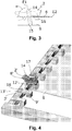
- the show accordingly Figs. 1 to 3 a clamping frame in which a substrate 6 is held.
- the clamping frame is part of a transport device of conventional design, which is not shown further here.
- the clamping frame has a frame body 1 which has at least one clamping strip 3.
- the clamping frame has two clamping strips 3.
- the clamping frame has at least one clamping holding means 2 for holding the substrate 6, the example shown having a plurality of clamping holding means 2.
- the respective clamping holding means 2 is composed of a first clamping member 8, a second clamping member 9, a swivel joint and an elastic element 14, the swivel joint being formed by associated parts of the first and second clamping members 8, 9.
- the first clamping member 8 has a clamping section 10 and an operating section 11.
- the second clamping member 9 is on the terminal strip 3 of the frame body 1 and the clamping section 10 of the first clamping member 8 lies opposite the second clamping member 9, the second clamping member 9 cooperating with the first clamping member 8.
- the swivel joint pivotally connects the second clamping member 9 to the first clamping member 8, forming a clamping gap 7.
- the elastic element 14 pretensions the clamping section 10 of the first clamping member 8 against the second clamping member 9, narrowing the clamping gap.
- a plurality of second clamping members 9 are integrally formed in a row next to one another on each terminal strip 3.
- the second clamping members 9 have a width B and a distance C from one another, which is preferably greater than the width B.
- the swivel joint represents a releasable connection between the first clamping member 8 and the second clamping member 9.
- the swivel joint includes a rotary shaft-like extension 12 on the first clamping member 8 and a corresponding recess 13 on the second clamping member 9, into which the extension 12 fits.
- the rotary joint or its extension 12 divides the first clamping member 8 into the clamping section 10 and the operating section 11.
- the rotating shaft-like extension 12 has the shape of an arc in cross section and protrudes axially over the two outer flanks of the first clamping member 8.
- the recess 13 has a corresponding circular arc-shaped cross section.
- the corresponding recess 13 is provided by a groove that is continuously formed in the terminal strip 3 over the length of the terminal strip 3.
- the frame body 1 is in the illustrated embodiment Figs. 1 to 3 rectangular and has two opposing connecting strips 4. These are each connected in one piece, for example, to the two opposite terminal strips 3.
- the connecting strips 4 are preferably composed of several telescopically extendable and retractable parts and are therefore adjustable in length.
- each connecting strip 4 has an expansion joint 5 in order to compensate for thermal expansion effects of the connecting strips 4.
- At least one terminal strip 3 can be made in several parts in an analogous manner in order to be able to vary its length.
- the elastic member 14 is an O-ring made of rubber.
- the elastic element 14 pretensions the clamping section of the first clamping element 8 against the second clamping element 9 by means of a prestressing force, narrowing the clamping gap.
- a receiving groove 15 is attached to the second clamping member 9, which prevents the O-ring from slipping off the clamp holding means 2 and thereby no longer pretensioning the clamp holding means 2.
- the first clamping member 8, on which the O-ring engages is shaped in such a way that the point of application of the O-ring on the first clamping member 8 is displaced in the direction of the swivel joint 12 if the O-ring unintentionally moves under from its mounted position Reduction of its ring diameter moves.
- the O-ring lies in a plane E1 which is oriented obliquely to a substrate surface or frame opening plane E2, that is to say it includes an angle ⁇ greater than 0 ° and less than 90 ° with it, the angle ⁇ z. B. in the range between 60 ° and 86 °.
- first clamping members 8 in the exemplary embodiment shown are from FIG Figs. 1 to 3 designed as separate components and a first clamping member 8 is mounted for each of the second clamping members 9 of the clamping frame.
- the separate first clamping members 8 are each held by the elastic element 14 on the associated second clamping member 9.
- the clamping frame forms an opening in which the substrate 6 is held.
- the second clamping members 9 of the clamping holding means 2 are oriented in such a way that they protrude into the opening and point in the direction of the opposite clamping strip 3.
- the substrate 6 is securely held in the clamping gap 7 of the clamping holding means 2 by the clamping force applied by the elastic element 14.
- a counterforce counteracting the pretensioning force of the elastic element 14 is exerted on the operating section 11.
- the first clamping member 8 is relative to the second Clamping member 9 is pivoted to enlarge the clamping gap and the substrate 6 can be removed from the opened clamping gap 7 or inserted into it.
- the second clamping member 9 and / or the first clamping member 8 can have a specially designed shape, e.g. B. in that the shape of the contact surfaces with which the clamp holding means 2 comes to rest against the substrate 6 are optimized.
- the second clamping member 9 has in the embodiment shown in FIG Figs. 1 to 3 via a contact section 16 which reduces the contact area with the substrate 6.
- the first clamping member 8 is designed in such a way that its contact with the substrate 6 is exactly opposite that of the contact section 16 with the substrate 6. For this purpose, a beak-shaped configuration of the first clamping member 8, as shown in FIG Fig. 3 can be seen.
- Fig. 4 is a section of a variant of the clamping frame of Figs. 1 to 3 shown in a perspective view, with corresponding reference numerals being used for identical or functionally equivalent elements and, in this regard, also to the above explanations on the exemplary embodiment of FIG Figs. 1 to 3 can be referenced.
- a rotating shaft-like extension 12 'of the rotary joint that has been modified in this respect does not protrude beyond the flanks of the first clamping member 8'.
- corresponding individual recesses or grooves 13' are formed in an associated elevation 18 of the terminal strip 3 '.
- the width of the elevation 18 is in the region of the width of the second clamping members 9 '.
- second clamping members 9 ' are integrally formed on the terminal strip 3'.
- the second clamping members 9 'from Fig. 4 are flat on the top, ie without the reduced contact section 16.
- a first clamping member 8 ' is mounted only for one of the second clamping members 9' to form a corresponding clamping holding means 2 ', the latter having a receiving groove 17 for the elastic element 14.
- the O-ring is held as the elastic element 14 in this receiving groove 17.
- the respective second clamping members 9 ', for which no first clamping member 8' is mounted serve as a substantially horizontal support for a clamped substrate 6.
- the second clamping members are implemented as components which are separate from the terminal strip and which can be detachably connected to the terminal strip.
- the use of components can be optimized in that only the second clamping members actually required for substrate clamping purposes are mounted on the terminal strip.
- the elastic element which biases the two clamping members a spring, such as. B. a tension, compression or a spiral spring.
- the clamping frame according to the invention is suitable and designed to be connected to a conventional frame conveyor and thus to provide a transport device for the substrate.
- the terminal strip or the connecting strip can have a connecting means to connect the clamping frame to z. B. to be able to mount circulating transport chains, so that the transport chains transport the clamping frame together with the substrate in a e.g. horizontal transport direction.
- the transport device By means of the transport device, the substrate held in the clamping frame, or a plurality of such flat substrates in clamping frames arranged one behind the other, can be fed to a treatment device and / or passed through the treatment device.
- the invention provides a clamping frame for functionally reliable handling of substrates which, in a very advantageous manner, only requires a small number of easily manufactured components and thus allows simplified assembly and needs-based modification of the clamping frame.
- the manufacturing costs can be kept low due to the small number of components.
Landscapes
- Engineering & Computer Science (AREA)
- Manufacturing & Machinery (AREA)
- Microelectronics & Electronic Packaging (AREA)
- Container, Conveyance, Adherence, Positioning, Of Wafer (AREA)
- Clamps And Clips (AREA)
Claims (10)
- Cadre de serrage pour un dispositif de transport servant au transport de substrats minces plats (6), en particulier de plaquettes de circuits, avec- un corps de cadre (1) présentant au moins une barrette de serrage (3), et- au moins un moyen de retenue de serrage (2) avec- un premier élément de serrage (8) présentant une section de serrage (10) et une section de commande (11),- un deuxième élément de serrage (9) arrangé sur la barrette de serrage du corps de cadre et opposé à la section de serrage du premier élément de serrage et coopérant avec le premier élément de serrage,- une articulation pivotante subdivisant le premier élément de serrage en la section de serrage et la section de commande et connectant le deuxième élément de serrage au premier élément de serrage en formant une fente de serrage (7) en pivotement, et- un élément élastique (14) effectuant un préserrage de la section de serrage du premier élément de serrage contre le deuxième élément de serrage en contractant la fente de serrage.
- Cadre de serrage selon la revendication 1, caractérisé en ce que l'articulation pivotante relie le premier élément de serrage au deuxième élément de serrage de manière amovible.
- Cadre de serrage selon l'une quelconque des revendications précédentes, caractérisé en ce que l'articulation pivotante présente un prolongement de type arbre rotatif (12) sur l'un élément de serrage et un renfoncement (13) correspondant sur l'autre élément de serrage.
- Cadre de serrage selon l'une quelconque des revendications précédentes, caractérisé en ce que le deuxième élément de serrage est relié à la barrette de serrage de manière amovible.
- Cadre de serrage selon l'une quelconque des revendications 1 à 3, caractérisé en ce que le deuxième élément de serrage fait une partie intégrale de la barrette de serrage.
- Cadre de serrage selon l'une quelconque des revendications précédentes, caractérisé en ce que- le corps de cadre présente au moins une barrette de connexion (4) qui comprend plusieurs parties et est ajustable en longueur, et/ou- la barrette de serrage comprend plusieurs parties et est ajustable en longueur.
- Cadre de serrage selon l'une quelconque des revendications précédentes, caractérisé en ce que l'élément élastique est un ressort ou un élément en caoutchouc.
- Cadre de serrage selon la revendication 7, caractérisé en ce que- l'élément en caoutchouc est un joint torique et/ou- le premier et/ou le deuxième élément de serrage présente une rainure de logement (15, 17) pour l'élément élastique.
- Cadre de serrage selon l'une quelconque des revendications précédentes, caractérisé en ce que- le cadre de serrage est rectangulaire et présente deux barrettes de connexion opposées et deux barrettes de serrage opposées,- chacune des deux barrettes de serrage présente une pluralité de deuxièmes éléments de serrage, lesdites deuxièmes éléments de serrage étant orientés vers la barrette de serrage opposée, et- les premiers éléments de serrage sont des composants particuliers, qui sont attachés à tous ou une partie des deuxièmes éléments de serrage des barrettes de serrage pour la formation du moyen de retenue de serrage associé.
- Dispositif de transport servant au transport de substrats minces plats, en particulier de plaquettes de circuits, comprenant- au moins un cadre de serrage selon l'une quelconque des revendications précédentes et- un moyen convoyeur de cadre circulant dans une direction de transport des substrats et relié au cadre de serrage.
Applications Claiming Priority (1)
| Application Number | Priority Date | Filing Date | Title |
|---|---|---|---|
| PCT/EP2017/070333 WO2019029813A1 (fr) | 2017-08-10 | 2017-08-10 | Cadre de serrage et dispositif de transport servant au transport de substrats |
Publications (2)
| Publication Number | Publication Date |
|---|---|
| EP3666049A1 EP3666049A1 (fr) | 2020-06-17 |
| EP3666049B1 true EP3666049B1 (fr) | 2021-09-29 |
Family
ID=59713986
Family Applications (1)
| Application Number | Title | Priority Date | Filing Date |
|---|---|---|---|
| EP17758083.4A Active EP3666049B1 (fr) | 2017-08-10 | 2017-08-10 | Cadre de serrage et dispositif de transport servant au transport de substrats |
Country Status (3)
| Country | Link |
|---|---|
| EP (1) | EP3666049B1 (fr) |
| CN (1) | CN111699765B (fr) |
| WO (1) | WO2019029813A1 (fr) |
Families Citing this family (2)
| Publication number | Priority date | Publication date | Assignee | Title |
|---|---|---|---|---|
| DE102020126486A1 (de) * | 2020-10-09 | 2022-04-14 | Phoenix Contact Gmbh & Co. Kg | Halterahmen für einen Steckverbinder |
| CN113488426B (zh) | 2021-07-01 | 2023-08-01 | 杭州中为光电技术有限公司 | 均分机构及脱胶装置 |
Family Cites Families (12)
| Publication number | Priority date | Publication date | Assignee | Title |
|---|---|---|---|---|
| DE3625038A1 (de) * | 1986-07-24 | 1988-01-28 | Siemens Ag | Vorrichtung zur halterung von flachbaugruppen |
| KR960015347B1 (ko) * | 1990-09-10 | 1996-11-09 | 후지쓰 가부시끼가이샤 | 반도체장치 |
| JPH0794067B2 (ja) * | 1990-10-08 | 1995-10-11 | 権士 近藤 | プリント基板の保持搬送方法およびその装置 |
| DE4337811A1 (de) | 1993-11-05 | 1995-05-11 | Philips Patentverwaltung | Anordnung zum Transportieren von gedruckten Schaltungsplatten |
| JP3044277B2 (ja) | 1994-12-21 | 2000-05-22 | 信越半導体株式会社 | ウェーハの洗浄及び洗浄乾燥装置 |
| WO1998039958A1 (fr) * | 1997-03-05 | 1998-09-11 | Ciba Specialty Chemicals Holding Inc. | Appareil de transport pour des substrats en forme de plaquettes minces |
| CA2280778A1 (fr) * | 1997-03-05 | 1998-09-11 | Ciba Specialty Chemicals Holding Inc. | Appareil de transport pour des substrats en forme de plaquettes minces |
| DE10131945A1 (de) | 2001-07-02 | 2003-01-30 | Siemens Dematic Ag | Verfahren zum gemeinsamen Bearbeiten von Leiterplatten |
| US7780825B2 (en) * | 2007-05-21 | 2010-08-24 | Lam Research Corporation | Substrate gripper with integrated electrical contacts |
| DE102007038116A1 (de) | 2007-07-30 | 2009-02-05 | Gebr. Schmid Gmbh & Co. | Haltemittel, Vorrichtung und Verfahren zum Transport von Substraten, insbesondere Leiterplatten |
| DE102009049905A1 (de) | 2009-10-12 | 2011-04-14 | Gebr. Schmid Gmbh & Co. | Halteeinrichtung für dünne flächige Substrate |
| JP6316402B2 (ja) * | 2013-03-27 | 2018-04-25 | エーファウ・グループ・エー・タルナー・ゲーエムベーハー | 基板スタックを取り扱うための、収容システム及び装置及び方法 |
-
2017
- 2017-08-10 WO PCT/EP2017/070333 patent/WO2019029813A1/fr not_active Ceased
- 2017-08-10 CN CN201780095709.6A patent/CN111699765B/zh active Active
- 2017-08-10 EP EP17758083.4A patent/EP3666049B1/fr active Active
Also Published As
| Publication number | Publication date |
|---|---|
| WO2019029813A1 (fr) | 2019-02-14 |
| CN111699765B (zh) | 2023-06-06 |
| CN111699765A (zh) | 2020-09-22 |
| EP3666049A1 (fr) | 2020-06-17 |
Similar Documents
| Publication | Publication Date | Title |
|---|---|---|
| EP2179438B1 (fr) | Moyens de maintien, dispositif de transport avec des moyens de maintien, et procédé pour le transport de substrats minces étendus, en particulier de circuits imprimés, avec un dispositif de transport | |
| EP2212223B1 (fr) | Système de guidage latéral | |
| DE102016000619A1 (de) | Abstreifer für Gurtföderer | |
| EP3666049B1 (fr) | Cadre de serrage et dispositif de transport servant au transport de substrats | |
| DE60026053T2 (de) | Führungschienenträger für fördersysteme | |
| EP2634822A1 (fr) | Dispositif de fixation de position d'un assembleur par soudage sur une cellule solaire | |
| DE102008059912B4 (de) | Messereinheit zum Schälen von langgestrecktem Schälgut | |
| EP1840242B1 (fr) | Dispositif de transport sous vide avec un rail de guidage déplaçable | |
| DE102011115865A1 (de) | Rollenförderer mit einer Drehmomentenstütze | |
| EP3081517B1 (fr) | Dispositif destiné à diriger et transporter des produits en forme de tronçon ou de fil | |
| DE3238992A1 (de) | Befestigungsanordnung fuer die leerlaufwalzen von foerderbaendern | |
| EP2525944B2 (fr) | Pilote de serrage d'une pièce sur un support et traineau porte- carrosserie utilisant un tel pilote | |
| DE102013003110B4 (de) | Schmierdüse | |
| DE102016210879A1 (de) | Klemmrahmen und Transportvorrichtung zum Transport von Substraten | |
| EP0908402B1 (fr) | Système à pince pour articles en forme de feuille | |
| DE2805776A1 (de) | Rotationsstempelvorrichtung | |
| DE102010045406A1 (de) | Vorrichtung zum Dosieren von Druckfarbe | |
| EP0569660A1 (fr) | Dispositif de support d'un substrat | |
| EP3551564A1 (fr) | Support de patin de rail pour fixer un rail d'une installation d'ascenseur | |
| DE102012023194A1 (de) | Justiervorrichtung | |
| WO2012175224A2 (fr) | Matrice de pliage | |
| DE102016012563B4 (de) | Vorrichtung und Verfahren zum Reinigen von Breitflacherzeugnissen | |
| DE102020131557A1 (de) | Fördergurt-Abstreifersystem mit einfacher Wartung | |
| DE102021002293B4 (de) | Substratträger mit Zentrierfunktion, Wechselstation mit einem Substratträger und Verfahren zum Behandeln eines Substrats | |
| DE102015013344B4 (de) | Vorrichtung zur befestigung eines objektes an einem oder mehreren trägerstoffen |
Legal Events
| Date | Code | Title | Description |
|---|---|---|---|
| STAA | Information on the status of an ep patent application or granted ep patent |
Free format text: STATUS: UNKNOWN |
|
| STAA | Information on the status of an ep patent application or granted ep patent |
Free format text: STATUS: THE INTERNATIONAL PUBLICATION HAS BEEN MADE |
|
| PUAI | Public reference made under article 153(3) epc to a published international application that has entered the european phase |
Free format text: ORIGINAL CODE: 0009012 |
|
| STAA | Information on the status of an ep patent application or granted ep patent |
Free format text: STATUS: REQUEST FOR EXAMINATION WAS MADE |
|
| 17P | Request for examination filed |
Effective date: 20200221 |
|
| AK | Designated contracting states |
Kind code of ref document: A1 Designated state(s): AL AT BE BG CH CY CZ DE DK EE ES FI FR GB GR HR HU IE IS IT LI LT LU LV MC MK MT NL NO PL PT RO RS SE SI SK SM TR |
|
| AX | Request for extension of the european patent |
Extension state: BA ME |
|
| DAV | Request for validation of the european patent (deleted) | ||
| DAX | Request for extension of the european patent (deleted) | ||
| GRAP | Despatch of communication of intention to grant a patent |
Free format text: ORIGINAL CODE: EPIDOSNIGR1 |
|
| STAA | Information on the status of an ep patent application or granted ep patent |
Free format text: STATUS: GRANT OF PATENT IS INTENDED |
|
| INTG | Intention to grant announced |
Effective date: 20210318 |
|
| RIN1 | Information on inventor provided before grant (corrected) |
Inventor name: SCHUSTER, MARC |
|
| GRAS | Grant fee paid |
Free format text: ORIGINAL CODE: EPIDOSNIGR3 |
|
| GRAA | (expected) grant |
Free format text: ORIGINAL CODE: 0009210 |
|
| STAA | Information on the status of an ep patent application or granted ep patent |
Free format text: STATUS: THE PATENT HAS BEEN GRANTED |
|
| AK | Designated contracting states |
Kind code of ref document: B1 Designated state(s): AL AT BE BG CH CY CZ DE DK EE ES FI FR GB GR HR HU IE IS IT LI LT LU LV MC MK MT NL NO PL PT RO RS SE SI SK SM TR |
|
| REG | Reference to a national code |
Ref country code: GB Ref legal event code: FG4D Free format text: NOT ENGLISH |
|
| REG | Reference to a national code |
Ref country code: CH Ref legal event code: EP Ref country code: AT Ref legal event code: REF Ref document number: 1435399 Country of ref document: AT Kind code of ref document: T Effective date: 20211015 |
|
| REG | Reference to a national code |
Ref country code: DE Ref legal event code: R096 Ref document number: 502017011616 Country of ref document: DE |
|
| REG | Reference to a national code |
Ref country code: IE Ref legal event code: FG4D Free format text: LANGUAGE OF EP DOCUMENT: GERMAN |
|
| REG | Reference to a national code |
Ref country code: LT Ref legal event code: MG9D |
|
| PG25 | Lapsed in a contracting state [announced via postgrant information from national office to epo] |
Ref country code: RS Free format text: LAPSE BECAUSE OF FAILURE TO SUBMIT A TRANSLATION OF THE DESCRIPTION OR TO PAY THE FEE WITHIN THE PRESCRIBED TIME-LIMIT Effective date: 20210929 Ref country code: SE Free format text: LAPSE BECAUSE OF FAILURE TO SUBMIT A TRANSLATION OF THE DESCRIPTION OR TO PAY THE FEE WITHIN THE PRESCRIBED TIME-LIMIT Effective date: 20210929 Ref country code: HR Free format text: LAPSE BECAUSE OF FAILURE TO SUBMIT A TRANSLATION OF THE DESCRIPTION OR TO PAY THE FEE WITHIN THE PRESCRIBED TIME-LIMIT Effective date: 20210929 Ref country code: NO Free format text: LAPSE BECAUSE OF FAILURE TO SUBMIT A TRANSLATION OF THE DESCRIPTION OR TO PAY THE FEE WITHIN THE PRESCRIBED TIME-LIMIT Effective date: 20211229 Ref country code: FI Free format text: LAPSE BECAUSE OF FAILURE TO SUBMIT A TRANSLATION OF THE DESCRIPTION OR TO PAY THE FEE WITHIN THE PRESCRIBED TIME-LIMIT Effective date: 20210929 Ref country code: BG Free format text: LAPSE BECAUSE OF FAILURE TO SUBMIT A TRANSLATION OF THE DESCRIPTION OR TO PAY THE FEE WITHIN THE PRESCRIBED TIME-LIMIT Effective date: 20211229 Ref country code: LT Free format text: LAPSE BECAUSE OF FAILURE TO SUBMIT A TRANSLATION OF THE DESCRIPTION OR TO PAY THE FEE WITHIN THE PRESCRIBED TIME-LIMIT Effective date: 20210929 |
|
| REG | Reference to a national code |
Ref country code: NL Ref legal event code: MP Effective date: 20210929 |
|
| PG25 | Lapsed in a contracting state [announced via postgrant information from national office to epo] |
Ref country code: LV Free format text: LAPSE BECAUSE OF FAILURE TO SUBMIT A TRANSLATION OF THE DESCRIPTION OR TO PAY THE FEE WITHIN THE PRESCRIBED TIME-LIMIT Effective date: 20210929 Ref country code: GR Free format text: LAPSE BECAUSE OF FAILURE TO SUBMIT A TRANSLATION OF THE DESCRIPTION OR TO PAY THE FEE WITHIN THE PRESCRIBED TIME-LIMIT Effective date: 20211230 |
|
| PG25 | Lapsed in a contracting state [announced via postgrant information from national office to epo] |
Ref country code: IS Free format text: LAPSE BECAUSE OF FAILURE TO SUBMIT A TRANSLATION OF THE DESCRIPTION OR TO PAY THE FEE WITHIN THE PRESCRIBED TIME-LIMIT Effective date: 20220129 Ref country code: SK Free format text: LAPSE BECAUSE OF FAILURE TO SUBMIT A TRANSLATION OF THE DESCRIPTION OR TO PAY THE FEE WITHIN THE PRESCRIBED TIME-LIMIT Effective date: 20210929 Ref country code: RO Free format text: LAPSE BECAUSE OF FAILURE TO SUBMIT A TRANSLATION OF THE DESCRIPTION OR TO PAY THE FEE WITHIN THE PRESCRIBED TIME-LIMIT Effective date: 20210929 Ref country code: PT Free format text: LAPSE BECAUSE OF FAILURE TO SUBMIT A TRANSLATION OF THE DESCRIPTION OR TO PAY THE FEE WITHIN THE PRESCRIBED TIME-LIMIT Effective date: 20220131 Ref country code: PL Free format text: LAPSE BECAUSE OF FAILURE TO SUBMIT A TRANSLATION OF THE DESCRIPTION OR TO PAY THE FEE WITHIN THE PRESCRIBED TIME-LIMIT Effective date: 20210929 Ref country code: NL Free format text: LAPSE BECAUSE OF FAILURE TO SUBMIT A TRANSLATION OF THE DESCRIPTION OR TO PAY THE FEE WITHIN THE PRESCRIBED TIME-LIMIT Effective date: 20210929 Ref country code: ES Free format text: LAPSE BECAUSE OF FAILURE TO SUBMIT A TRANSLATION OF THE DESCRIPTION OR TO PAY THE FEE WITHIN THE PRESCRIBED TIME-LIMIT Effective date: 20210929 Ref country code: EE Free format text: LAPSE BECAUSE OF FAILURE TO SUBMIT A TRANSLATION OF THE DESCRIPTION OR TO PAY THE FEE WITHIN THE PRESCRIBED TIME-LIMIT Effective date: 20210929 Ref country code: CZ Free format text: LAPSE BECAUSE OF FAILURE TO SUBMIT A TRANSLATION OF THE DESCRIPTION OR TO PAY THE FEE WITHIN THE PRESCRIBED TIME-LIMIT Effective date: 20210929 Ref country code: AL Free format text: LAPSE BECAUSE OF FAILURE TO SUBMIT A TRANSLATION OF THE DESCRIPTION OR TO PAY THE FEE WITHIN THE PRESCRIBED TIME-LIMIT Effective date: 20210929 |
|
| REG | Reference to a national code |
Ref country code: DE Ref legal event code: R097 Ref document number: 502017011616 Country of ref document: DE |
|
| PG25 | Lapsed in a contracting state [announced via postgrant information from national office to epo] |
Ref country code: DK Free format text: LAPSE BECAUSE OF FAILURE TO SUBMIT A TRANSLATION OF THE DESCRIPTION OR TO PAY THE FEE WITHIN THE PRESCRIBED TIME-LIMIT Effective date: 20210929 |
|
| PLBE | No opposition filed within time limit |
Free format text: ORIGINAL CODE: 0009261 |
|
| STAA | Information on the status of an ep patent application or granted ep patent |
Free format text: STATUS: NO OPPOSITION FILED WITHIN TIME LIMIT |
|
| 26N | No opposition filed |
Effective date: 20220630 |
|
| PG25 | Lapsed in a contracting state [announced via postgrant information from national office to epo] |
Ref country code: SI Free format text: LAPSE BECAUSE OF FAILURE TO SUBMIT A TRANSLATION OF THE DESCRIPTION OR TO PAY THE FEE WITHIN THE PRESCRIBED TIME-LIMIT Effective date: 20210929 |
|
| PG25 | Lapsed in a contracting state [announced via postgrant information from national office to epo] |
Ref country code: IT Free format text: LAPSE BECAUSE OF FAILURE TO SUBMIT A TRANSLATION OF THE DESCRIPTION OR TO PAY THE FEE WITHIN THE PRESCRIBED TIME-LIMIT Effective date: 20210929 |
|
| PG25 | Lapsed in a contracting state [announced via postgrant information from national office to epo] |
Ref country code: MC Free format text: LAPSE BECAUSE OF FAILURE TO SUBMIT A TRANSLATION OF THE DESCRIPTION OR TO PAY THE FEE WITHIN THE PRESCRIBED TIME-LIMIT Effective date: 20210929 |
|
| GBPC | Gb: european patent ceased through non-payment of renewal fee |
Effective date: 20220810 |
|
| PG25 | Lapsed in a contracting state [announced via postgrant information from national office to epo] |
Ref country code: LU Free format text: LAPSE BECAUSE OF NON-PAYMENT OF DUE FEES Effective date: 20220810 |
|
| REG | Reference to a national code |
Ref country code: BE Ref legal event code: MM Effective date: 20220831 |
|
| PG25 | Lapsed in a contracting state [announced via postgrant information from national office to epo] |
Ref country code: IE Free format text: LAPSE BECAUSE OF NON-PAYMENT OF DUE FEES Effective date: 20220810 Ref country code: FR Free format text: LAPSE BECAUSE OF NON-PAYMENT OF DUE FEES Effective date: 20220831 |
|
| PG25 | Lapsed in a contracting state [announced via postgrant information from national office to epo] |
Ref country code: BE Free format text: LAPSE BECAUSE OF NON-PAYMENT OF DUE FEES Effective date: 20220831 |
|
| PG25 | Lapsed in a contracting state [announced via postgrant information from national office to epo] |
Ref country code: GB Free format text: LAPSE BECAUSE OF NON-PAYMENT OF DUE FEES Effective date: 20220810 |
|
| PG25 | Lapsed in a contracting state [announced via postgrant information from national office to epo] |
Ref country code: SM Free format text: LAPSE BECAUSE OF FAILURE TO SUBMIT A TRANSLATION OF THE DESCRIPTION OR TO PAY THE FEE WITHIN THE PRESCRIBED TIME-LIMIT Effective date: 20210929 Ref country code: CY Free format text: LAPSE BECAUSE OF FAILURE TO SUBMIT A TRANSLATION OF THE DESCRIPTION OR TO PAY THE FEE WITHIN THE PRESCRIBED TIME-LIMIT Effective date: 20210929 |
|
| PG25 | Lapsed in a contracting state [announced via postgrant information from national office to epo] |
Ref country code: MK Free format text: LAPSE BECAUSE OF FAILURE TO SUBMIT A TRANSLATION OF THE DESCRIPTION OR TO PAY THE FEE WITHIN THE PRESCRIBED TIME-LIMIT Effective date: 20210929 Ref country code: HU Free format text: LAPSE BECAUSE OF FAILURE TO SUBMIT A TRANSLATION OF THE DESCRIPTION OR TO PAY THE FEE WITHIN THE PRESCRIBED TIME-LIMIT; INVALID AB INITIO Effective date: 20170810 |
|
| PG25 | Lapsed in a contracting state [announced via postgrant information from national office to epo] |
Ref country code: MT Free format text: LAPSE BECAUSE OF FAILURE TO SUBMIT A TRANSLATION OF THE DESCRIPTION OR TO PAY THE FEE WITHIN THE PRESCRIBED TIME-LIMIT Effective date: 20210929 |
|
| PG25 | Lapsed in a contracting state [announced via postgrant information from national office to epo] |
Ref country code: TR Free format text: LAPSE BECAUSE OF FAILURE TO SUBMIT A TRANSLATION OF THE DESCRIPTION OR TO PAY THE FEE WITHIN THE PRESCRIBED TIME-LIMIT Effective date: 20210929 |
|
| REG | Reference to a national code |
Ref country code: CH Ref legal event code: U11 Free format text: ST27 STATUS EVENT CODE: U-0-0-U10-U11 (AS PROVIDED BY THE NATIONAL OFFICE) Effective date: 20260122 |
|
| PGFP | Annual fee paid to national office [announced via postgrant information from national office to epo] |
Ref country code: DE Payment date: 20260120 Year of fee payment: 9 |
|
| PGFP | Annual fee paid to national office [announced via postgrant information from national office to epo] |
Ref country code: AT Payment date: 20260123 Year of fee payment: 9 |
|
| PGFP | Annual fee paid to national office [announced via postgrant information from national office to epo] |
Ref country code: CH Payment date: 20260122 Year of fee payment: 9 |