EP3666059A1 - Machine agricole de récolte - Google Patents
Machine agricole de récolte Download PDFInfo
- Publication number
- EP3666059A1 EP3666059A1 EP19211473.4A EP19211473A EP3666059A1 EP 3666059 A1 EP3666059 A1 EP 3666059A1 EP 19211473 A EP19211473 A EP 19211473A EP 3666059 A1 EP3666059 A1 EP 3666059A1
- Authority
- EP
- European Patent Office
- Prior art keywords
- conveyor
- harvesting machine
- rotor
- agricultural harvesting
- machine according
- Prior art date
- Legal status (The legal status is an assumption and is not a legal conclusion. Google has not performed a legal analysis and makes no representation as to the accuracy of the status listed.)
- Granted
Links
Images

Classifications
-
- A—HUMAN NECESSITIES
- A01—AGRICULTURE; FORESTRY; ANIMAL HUSBANDRY; HUNTING; TRAPPING; FISHING
- A01D—HARVESTING; MOWING
- A01D84/00—Haymakers not provided for in a single one of groups A01D76/00 - A01D82/00
-
- A—HUMAN NECESSITIES
- A01—AGRICULTURE; FORESTRY; ANIMAL HUSBANDRY; HUNTING; TRAPPING; FISHING
- A01D—HARVESTING; MOWING
- A01D89/00—Pick-ups for loaders, chaff-cutters, balers, field-threshers, or the like, i.e. attachments for picking-up hay or the like field crops
- A01D89/006—Accessories
- A01D89/008—Devices cooperating with the pick-up
Definitions
- the present invention relates to an agricultural harvesting machine, in particular a belt swather or merger, with a pick-up conveyor for picking up crop material from the ground, comprising a spiked rotor which has conveyor tines which can be driven all round, a connecting conveyor to which the pick-up conveyor transfers the crop material picked up from the ground, and one the spike rotor arranged conveying aid to support the transfer of crop from the spiked roller to the connecting conveyor.
- spiked rollers In agricultural harvesting machines such as mergers or belt swathers, it is known to pick up cut crops such as hay and grass from the ground by means of a rotating spiked roller, which is sometimes also referred to as a pickup.
- a rotating spiked roller which is sometimes also referred to as a pickup.
- Such spiked rollers regularly lie transversely to the direction of travel and have a large number of conveyor tines which are controlled or driven uncontrolled along an orbit.
- the mentioned orbits of the conveyor tines extend upright approximately parallel to the direction of travel, the conveyor tines can rotate along a circular path about a fixed axis of rotation in the case of uncontrolled formation and can tilt and / or extend and retract and extend in addition to the orbital movement in the case of a controlled formation, the aforementioned Orbit often deviate from the circular shape and a control movement along the orbit can take place through a cam control surface, for example in the form of a guide link or by crank control lever.
- wipers are provided between the conveyor tines, which are usually designed in the form of strip-shaped wiper plates and are delimited between gap-shaped recesses in which the conveyor tines are arranged and more or less far extend beyond the scraper plates or retreat between them.
- the orbits of the conveyor tines extend coplanar to the gap-shaped recesses, a single conveyor tine or tines combined in pairs or groups being able to run in a respective gap between two adjacent wipers.
- the wipers extend in an arc around the center of the conveyor tine orbit and run in the storage area in which the crop is to be wiped off the conveyor tines, usually tangentially or slightly curved beyond the conveyor tine orbit, so that the conveyor tines submerge between the wipers and thereby stripping the crop.
- the crop tends to stick or stick to the stripper plates, especially if the crop is moist, such as grass.
- the script DE 10 2017 001 012 A1 proposed to replace the scraper plates by rotating conveyor belts, between which the conveyor tines of the pickup rotate.
- the wiper plates in the wiping area to be replaced by revolving conveyor paddles, which are immersed between the orbits of the pickup tines and actively lift the crop away from it.
- dry crops such as dried hay or straw in particular tend not to follow the orbit of the pickup conveyor tines but to be thrown upwards by the conveyor tines, so that the crops are thrown off does not even reach the scraper area. Due to the crop falling back and then picked up again, there is an uneven, pulsating feed intake, so that a uniform crop flow cannot be achieved on the connecting conveyor.
- the font EP 31 35 099 A1 suggests, with regard to this problem, to arrange an additional conveying aid in the form of a rotating reel above the spiked rotor, which rotates in the opposite direction to the spiked rotor and drives the crop thrown up by the spiked rotor onto the downstream cross conveyor belt or does not even allow the crop to be removed from the Spiked roller the pickup is thrown upwards.
- the crop from the pickup spiked roller does not always slide in the same direction or in the same sector, it is not easy to position the reel correctly in relation to the spike rotor in order to reliably pick up and pick up the crop to hand over the cross conveyor. If the reel is made larger in order to have a larger detection area, the device becomes bulky. If the named reel is movably or displaceably mounted, the area of engagement could be corrected.
- this requires the varying discharge area of the spiked roller comprises or a complex control for the reel position can be provided.
- the object of the present invention is to provide an improved agricultural harvesting machine of the type mentioned which avoids the disadvantages of the prior art and advantageously develops the latter.
- a reliable transfer of the picked-up crop from the pickup to the connecting conveyor is to be achieved, even if the picked-up crop quantity varies and the direction or position at which the picked-up crop detaches from the pickup is inconsistent.
- the directional impact surface as a conveying aid for transferring the crop to the connection conveyor above the spiked rotor, which deflects the crop thrown upwards by the spiked rotor and directs it to the connection conveyor.
- the directional impact surface extends at an acute angle to the ejection direction and / or approximately in the circumferential direction of the spiked rotor and leads crops thrown off by the spiked rotor to the connecting conveyor.
- Such an impact surface which is inclined at an acute angle or approximately nestles around the spiked rotor, can cover a larger discharge area in order to pick up the crop that is detaching from the spiked rotor when the conveying conditions vary and to guide it safely to the connecting conveyor.
- the baffle surface mentioned can in particular be designed as a baffle cloth that is spanned by a clamping frame.
- a textile or foil-like baffle cloth is not only characterized by its low weight, but also has a certain flexibility or deformability, so that the baffle surface adapt to different amounts of feed and still achieve the desired directional guidance.
- the impact cloth forms on its side facing the spiked rotor a smooth, closed surface without at least major unevenness, so that the crop can slide along the impact surface with relatively little resistance.
- This also applies in particular in a direction transverse to the conveying direction of the spiked rotor, as a result of which the crop material sliding along the impact cloth can also slide or be conveyed off obliquely or transversely when it comes into the engagement area of the connecting conveyor.
- the impact cloth also allows the crop to slide off at an angle if this is necessary.
- the impact cloth fulfills its direction-providing function, in particular in that the crop is deflected towards the connection conveyor when it is thrown straight or diagonally upwards by the spiked roller.
- the baffle cloth mentioned can be clamped on a clamping frame, which comprises a plurality of longitudinal ribs, which extend at least approximately parallel to the conveying direction of the crop along the baffle surface spanned by the baffle cloth and are fastened to the baffle cloth.
- the mentioned longitudinal ribs can at least approximately extend in planes which are aligned perpendicular to the axis of rotation of the spiked rotor.
- the longitudinal ribs mentioned which span the baffle and / or support the desired contour or profile of the baffle, can be designed to be elastic or resilient in order to give the baffle the desired shape, but at the same time to maintain its flexibility or to promote in order to achieve a better adaptation of the baffle to varying amounts of feed.
- longitudinal ribs mentioned can be designed as spring elements, for example in the form of spring slats.
- the above-mentioned longitudinal ribs of the clamping frame can be accommodated in pockets and / or tabs of the impact cloth. If flat spring slats are used as the longitudinal ribs, they can be inserted into corresponding slatted pockets of the baffle cloth in the manner of sail slats, as used in sails of boats or surfboards. If necessary, they can also be attached to the impact cloth by means of one or more tabs in order to hold the impact cloth along the contour of the spring slat on the latter.
- Said longitudinal ribs can advantageously be fastened in a cantilever manner to a cross member which extends approximately parallel to the axis of rotation of the spiked rotor and can form a leading edge or a trailing edge of the impact surface.
- the baffle cloth can include receiving pockets for the longitudinal ribs that are open toward the said cross member, so that the baffle cloth with the said receiving pockets can be slipped onto the longitudinal ribs. This allows the baffle cloth to be easily assembled and changed.
- the impact surface can extend, in particular, in the area of the spiked rotor that is prone to ejection.
- the baffle area can extend in a sector from about 1 a.m. to 2 a.m. or 3 a.m. to 1 a.m. or 3 a.m. to 12 p.m. or 2 a.m. to 12 p.m. points and / or 9 a.m. to the connecting conveyor.
- the baffle surface can be slightly trough-shaped, concave toward the spike rotor.
- the impact surface can be viewed in a sectional plane perpendicular to the circumferential axis of the spiked rotor, and can be inclined at an acute angle to the vertical, the said inclination angle can extend to the vertical in the range from 10 ° to 80 ° or 25 ° to 65 ° or 30 ° to 60 °, for example about 40 ° to 50 °. If the baffle has the aforementioned groove-shaped curvature, the angle of inclination to the vertical can vary slightly, depending on which point of the baffle you are looking at.
- a rotatable infeed roller or several rotatable infeed rollers can be provided on the infeed edge of the baffle cloth, such an infeed roller or infeed roller being able to be actively driven, in particular counter to the spiked roller of the pickup.
- connection conveyor connected downstream of the spiked rotor can be a cross conveyor which transports the harvested crop transversely to the conveying direction of the spiked rotor.
- a cross conveyor can in particular be designed as an endlessly rotating cross conveyor, for example in the form of a conveyor belt or a chain conveyor.
- the harvesting machine 1 shown in the figures can be designed for attachment to a tractor (not shown) and, for this purpose, can comprise, for example, an attachment bracket which can be attached to the tractor by means of a three-point linkage or have a drawbar in order to design the harvesting machine as a semi-trailer and to be able to attach it to the tractor .
- the above-mentioned harvesting machine 1 can be designed in the form of a belt swather or merger, as shown in the figures, alternatively, if appropriate, an embodiment as a loading wagon and / or baler can also be considered.
- the harvesting machine 1 can comprise a machine frame 3, which can be supported on the ground by means of a chassis 2, but can optionally also be suspended from the tractor via a trestle.
- Said machine frame 3 carries a receiving conveyor 4, which collects crop material from the ground and transfers it to a connecting conveyor 5, which can be designed in the form of a cross conveyor to convey the crop material transversely to the direction of travel 6 and deposit it in a swath.
- connection conveyor 5 can in particular comprise a cross conveyor belt 15 which can be driven endlessly all round and forms an approximately lying storage and conveying surface on which the receiving conveyor 4 deposits the crop.
- the receiving conveyor 4 can have a spiked rotor 7 which is arranged in a lying position and can extend with its axis of rotation 9 lying transversely to the direction of travel.
- the conveyor tines 8 of the spiked rotor 7 can rotate uncontrolled about the rotation axis 9 mentioned on a circular path or can also be controlled on a possibly non-circular orbit around said rotation axis 9, as explained at the beginning.
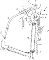
- Said spiked rotor 7 can have scraper strips 10 arranged between the conveyor tines 8 and extending in an arc around the circumferential axis 9, between which the conveyor tines 8 extend, cf. Figure 1 .
- the top of the spiked rotor 7 and / or the downstream region of the stripper strips 10 mentioned can be arranged at least approximately at the level of the connecting conveyor 5 in order to be able to transfer the crop gently to the connecting conveyor 5.
- a conveying aid 11 which has a baffle cloth 13 that is nestled around the circumference of the spiked rotor 7 or arranged at an acute angle to the radial direction from the spiked rotor 7, the side of which facing the spiked rotor 7 forms an impact surface 12 in order to be separated from the spiked rotor 7 to guide the thrown crop backwards to the cross conveyor belt 15.
- said baffle 12 in the direction of the axis of rotation 9, said baffle 12 extends in a segment from about 2 a.m. to 1 a.m. or 3 a.m. to 12 noon or in a quadrant which lies in the direction of travel at the front and above the spiked rotor 7.
- the impact surface 12 When viewed in a sectional plane perpendicular to the axis of rotation 9, the impact surface 12 can extend over an angular segment of 30 ° to 120 ° or 30 ° to 90 ° or also 30 ° to 70 °.
- the aforementioned baffle surface 12 can be concave, approximately gutter-shaped on its side facing the spiked rotor 7, although in principle a flat design is also possible.
- said baffle surface 12 extends at an acute angle to the vertical, for example at an angle of approximately 30 ° to 60 °.
- the baffle 12 is formed by a baffle 13, which is stretched on a clamping frame 14.
- Said clamping frame 14 can comprise a cross member 16, which can lie horizontally transversely to the direction of travel and / or parallel to the axis of rotation 9 and can form a leading edge of the impact fabric 13.
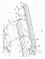
- Longitudinal ribs 17 protrude from said cross member 16, which ribs can extend in the conveying direction of the crop along the baffle surface 12 and can be spaced apart from one another transversely to the conveying direction and distributed over the width of the baffle cloth 13, cf. Figure 2 .
- Said longitudinal ribs 17 can be designed, for example, in the form of spring bars or spring slats in order to stretch the baffle cloth 13 elastically.
- the spring slats forming the longitudinal ribs 17 can have a slightly curved contour or have a slightly curved basic contour in order to stretch the baffle cloth 13 with a slightly contoured groove.
- the baffle cloth 13 can have receiving pockets into which the said longitudinal ribs 17 can be inserted, or the receiving pockets 18 of the baffle cloth 13 can be open towards the cross member 16, so that the baffle cloth 13 with the receiving pockets 18 can be slipped onto the longitudinal ribs 17.
- the impact cloth 13 can be fixed to the cross member 16, for example by means of a clamping strip.
- the baffle cloth 13 can consist of a textile material or of a film or of a composite material, for example a coated fabric, which on the one hand has sufficient tear strength and on the other hand has a smooth surface that allows the crop to slide easily.
- FIG. 1 and 2nd show, can be arranged on the leading edge of the baffle 13 an inlet roller 19, the roller axis of rotation 20 lying transversely to the direction of travel and / or approximately parallel to the axis of rotation 9 of the spiked rotor 7 can be aligned.
- the inlet roller 19, like the impact cloth 13, can extend over the substantially entire width of the spiked rotor.
- Said inlet rotor 19 can rotate freely without being driven, but possibly also be driven, in particular in the opposite direction to the spiked roller 7.
- the impact cloth 13 and the inlet roller 19 are fastened to the machine frame 3 of the harvesting machine 1 via one or more support arms 21.
- the support arms 21 can be mounted about a horizontal support arm pivot axis 22 oriented transversely to the direction of travel, in order to be able to adjust the distance between the baffle cloth 13 and the prick roller 7 and / or to pivot it away from the prick roller 7, in particular out of the position shown in FIGS Figures 1 and 2nd shown working position upwards away from the spiked rotor 7 in a maintenance and / or inactive position.
- Figure 3 illustrates the impending crop dropping from the spiked rotor 7 when the impact cloth 13 is pivoted away or removed.
- the three arrows 23 illustrate the possible throwing directions from the spiked rotor 7 upwards and / or obliquely to the front.
- the baffle 13 and the feed roller 19 is provided, as is the Figures 1 and 2nd demonstrate.
Landscapes
- Life Sciences & Earth Sciences (AREA)
- Environmental Sciences (AREA)
- Harvesting Machines For Root Crops (AREA)
- Organic Low-Molecular-Weight Compounds And Preparation Thereof (AREA)
Applications Claiming Priority (1)
| Application Number | Priority Date | Filing Date | Title |
|---|---|---|---|
| DE202018107018.5U DE202018107018U1 (de) | 2018-12-10 | 2018-12-10 | Landwirtschaftliche Erntemaschine |
Publications (2)
| Publication Number | Publication Date |
|---|---|
| EP3666059A1 true EP3666059A1 (fr) | 2020-06-17 |
| EP3666059B1 EP3666059B1 (fr) | 2021-08-25 |
Family
ID=65235503
Family Applications (1)
| Application Number | Title | Priority Date | Filing Date |
|---|---|---|---|
| EP19211473.4A Active EP3666059B1 (fr) | 2018-12-10 | 2019-11-26 | Machine agricole de récolte |
Country Status (2)
| Country | Link |
|---|---|
| EP (1) | EP3666059B1 (fr) |
| DE (1) | DE202018107018U1 (fr) |
Families Citing this family (2)
| Publication number | Priority date | Publication date | Assignee | Title |
|---|---|---|---|---|
| PL246847B1 (pl) * | 2022-10-28 | 2025-03-17 | Samasz Spolka Z Ograniczona Odpowiedzialnoscia | Maszyna rolnicza, zwłaszcza do zbierania pokosów traw i innych roślin |
| ES3037929T3 (en) * | 2022-12-01 | 2025-10-08 | Roc S R L | Windrow merger and method for forming windrows through a windrow merger which collects agricultural products from a field |
Citations (9)
| Publication number | Priority date | Publication date | Assignee | Title |
|---|---|---|---|---|
| US4539798A (en) * | 1982-03-26 | 1985-09-10 | National Research Development Corporation | Apparatus and method for conveying and/or treating crop |
| US4720962A (en) * | 1982-07-29 | 1988-01-26 | National Research Development Corporation | Apparatus for picking up and conveying crop or other material |
| US7650741B2 (en) * | 2007-01-05 | 2010-01-26 | Agco Corporation | Articulating windguard for agricultural baler |
| EP2156729A2 (fr) * | 2008-08-19 | 2010-02-24 | Deere & Company | Dispositif d'assujettissement |
| EP2941946A1 (fr) * | 2014-05-05 | 2015-11-11 | Roc S.R.L. | Unité de guidage pour produits agricoles destinée à un dispositif servant à récolter les produits agricoles et dispositif comprenant l'unité de guidage |
| US9386749B1 (en) * | 2015-03-31 | 2016-07-12 | Black Creek, LLC | Product to windrows pickup head |
| EP3135099A1 (fr) | 2015-08-27 | 2017-03-01 | Josef Knüsel | Machine agricole comprenant un dispositif de ramassage |
| DE202017000595U1 (de) | 2017-02-03 | 2018-05-08 | Pöttinger Landtechnik Gmbh | Landwirtschaftliche Erntemaschine |
| DE102017001012A1 (de) | 2017-02-03 | 2018-08-09 | Pöttinger Landtechnik Gmbh | Landwirtschaftliche Erntemaschine |
-
2018
- 2018-12-10 DE DE202018107018.5U patent/DE202018107018U1/de active Active
-
2019
- 2019-11-26 EP EP19211473.4A patent/EP3666059B1/fr active Active
Patent Citations (9)
| Publication number | Priority date | Publication date | Assignee | Title |
|---|---|---|---|---|
| US4539798A (en) * | 1982-03-26 | 1985-09-10 | National Research Development Corporation | Apparatus and method for conveying and/or treating crop |
| US4720962A (en) * | 1982-07-29 | 1988-01-26 | National Research Development Corporation | Apparatus for picking up and conveying crop or other material |
| US7650741B2 (en) * | 2007-01-05 | 2010-01-26 | Agco Corporation | Articulating windguard for agricultural baler |
| EP2156729A2 (fr) * | 2008-08-19 | 2010-02-24 | Deere & Company | Dispositif d'assujettissement |
| EP2941946A1 (fr) * | 2014-05-05 | 2015-11-11 | Roc S.R.L. | Unité de guidage pour produits agricoles destinée à un dispositif servant à récolter les produits agricoles et dispositif comprenant l'unité de guidage |
| US9386749B1 (en) * | 2015-03-31 | 2016-07-12 | Black Creek, LLC | Product to windrows pickup head |
| EP3135099A1 (fr) | 2015-08-27 | 2017-03-01 | Josef Knüsel | Machine agricole comprenant un dispositif de ramassage |
| DE202017000595U1 (de) | 2017-02-03 | 2018-05-08 | Pöttinger Landtechnik Gmbh | Landwirtschaftliche Erntemaschine |
| DE102017001012A1 (de) | 2017-02-03 | 2018-08-09 | Pöttinger Landtechnik Gmbh | Landwirtschaftliche Erntemaschine |
Also Published As
| Publication number | Publication date |
|---|---|
| DE202018107018U1 (de) | 2019-01-16 |
| EP3666059B1 (fr) | 2021-08-25 |
Similar Documents
| Publication | Publication Date | Title |
|---|---|---|
| DE60219756T2 (de) | Gerät zur Behandlung von Erntegut | |
| DE102013204977B4 (de) | Schneidwerk mit Querförderbändern und um die Hochachse schwenkbaren Förderwalzen | |
| DE2848451C2 (fr) | ||
| DE102007017911B4 (de) | Landwirtschaftliche Erntemaschine | |
| EP1199920A1 (fr) | Appareil de moissonnage | |
| DE202017000595U1 (de) | Landwirtschaftliche Erntemaschine | |
| EP3357325A1 (fr) | Moissonneuse | |
| EP1428423B1 (fr) | Dispositif de prise et de cueillette | |
| EP3666059B1 (fr) | Machine agricole de récolte | |
| DE2365029C3 (de) | Erntemaschine mit einer Erntebergungsvorrichtung zur Aufnahme von Erntegut vom Feld | |
| EP1530893B1 (fr) | Dispositif de récolte | |
| DE2363293A1 (de) | Erntevorsatz fuer in reihe stehendes getreide, insbesondere fuer mais, mit einem rotor zum erfassen der ueber dem leitblech in die benachbarte reihe ueberhaengenden stengelteile | |
| DE19501382B4 (de) | Lade- und Fördervorrichtung eines Selbstladewagens | |
| EP3669638A1 (fr) | Engin d'abattage-façonnage agricole | |
| EP4338575A1 (fr) | Moissonneuse agricole | |
| DE10135128C1 (de) | Erntegerät für stengelartiges Erntegut | |
| DE102006061010B4 (de) | Erntemaschine | |
| DE10320042A1 (de) | Landwirtschaftsmaschine zum Kreiseln und Schwadern von gemähtem Bodenwuchs | |
| DE2448556A1 (de) | Kreiselheuwerbungsmaschine | |
| DE102022112868B3 (de) | Vorrichtung für die Ernte stängeligen Ernteguts | |
| DE102018131772A1 (de) | Erntemaschine | |
| DE102004028245B4 (de) | Maisernte-Vorsatz zum Anbau an eine selbstfahrende Erntemaschine | |
| CH665085A5 (de) | Schwadvorrichtung an der rueckseite einer halmguterntemaschine. | |
| DE102007002670B4 (de) | Maschine zum Mähen von stängelartigem Erntegut | |
| DE102007001951B4 (de) | Pflückeinrichtung zur Ernte von Fruchtständen von Pflanzen |
Legal Events
| Date | Code | Title | Description |
|---|---|---|---|
| PUAI | Public reference made under article 153(3) epc to a published international application that has entered the european phase |
Free format text: ORIGINAL CODE: 0009012 |
|
| STAA | Information on the status of an ep patent application or granted ep patent |
Free format text: STATUS: THE APPLICATION HAS BEEN PUBLISHED |
|
| AK | Designated contracting states |
Kind code of ref document: A1 Designated state(s): AL AT BE BG CH CY CZ DE DK EE ES FI FR GB GR HR HU IE IS IT LI LT LU LV MC MK MT NL NO PL PT RO RS SE SI SK SM TR |
|
| AX | Request for extension of the european patent |
Extension state: BA ME |
|
| STAA | Information on the status of an ep patent application or granted ep patent |
Free format text: STATUS: REQUEST FOR EXAMINATION WAS MADE |
|
| 17P | Request for examination filed |
Effective date: 20201215 |
|
| RBV | Designated contracting states (corrected) |
Designated state(s): AL AT BE BG CH CY CZ DE DK EE ES FI FR GB GR HR HU IE IS IT LI LT LU LV MC MK MT NL NO PL PT RO RS SE SI SK SM TR |
|
| GRAP | Despatch of communication of intention to grant a patent |
Free format text: ORIGINAL CODE: EPIDOSNIGR1 |
|
| STAA | Information on the status of an ep patent application or granted ep patent |
Free format text: STATUS: GRANT OF PATENT IS INTENDED |
|
| RIC1 | Information provided on ipc code assigned before grant |
Ipc: A01D 84/00 20060101ALI20210407BHEP Ipc: A01D 89/00 20060101AFI20210407BHEP |
|
| INTG | Intention to grant announced |
Effective date: 20210428 |
|
| GRAS | Grant fee paid |
Free format text: ORIGINAL CODE: EPIDOSNIGR3 |
|
| GRAA | (expected) grant |
Free format text: ORIGINAL CODE: 0009210 |
|
| STAA | Information on the status of an ep patent application or granted ep patent |
Free format text: STATUS: THE PATENT HAS BEEN GRANTED |
|
| AK | Designated contracting states |
Kind code of ref document: B1 Designated state(s): AL AT BE BG CH CY CZ DE DK EE ES FI FR GB GR HR HU IE IS IT LI LT LU LV MC MK MT NL NO PL PT RO RS SE SI SK SM TR |
|
| REG | Reference to a national code |
Ref country code: CH Ref legal event code: EP |
|
| REG | Reference to a national code |
Ref country code: DE Ref legal event code: R096 Ref document number: 502019002132 Country of ref document: DE |
|
| REG | Reference to a national code |
Ref country code: IE Ref legal event code: FG4D Free format text: LANGUAGE OF EP DOCUMENT: GERMAN Ref country code: AT Ref legal event code: REF Ref document number: 1422837 Country of ref document: AT Kind code of ref document: T Effective date: 20210915 |
|
| REG | Reference to a national code |
Ref country code: LT Ref legal event code: MG9D |
|
| REG | Reference to a national code |
Ref country code: NL Ref legal event code: MP Effective date: 20210825 |
|
| PG25 | Lapsed in a contracting state [announced via postgrant information from national office to epo] |
Ref country code: ES Free format text: LAPSE BECAUSE OF FAILURE TO SUBMIT A TRANSLATION OF THE DESCRIPTION OR TO PAY THE FEE WITHIN THE PRESCRIBED TIME-LIMIT Effective date: 20210825 Ref country code: RS Free format text: LAPSE BECAUSE OF FAILURE TO SUBMIT A TRANSLATION OF THE DESCRIPTION OR TO PAY THE FEE WITHIN THE PRESCRIBED TIME-LIMIT Effective date: 20210825 Ref country code: SE Free format text: LAPSE BECAUSE OF FAILURE TO SUBMIT A TRANSLATION OF THE DESCRIPTION OR TO PAY THE FEE WITHIN THE PRESCRIBED TIME-LIMIT Effective date: 20210825 Ref country code: BG Free format text: LAPSE BECAUSE OF FAILURE TO SUBMIT A TRANSLATION OF THE DESCRIPTION OR TO PAY THE FEE WITHIN THE PRESCRIBED TIME-LIMIT Effective date: 20211125 Ref country code: LT Free format text: LAPSE BECAUSE OF FAILURE TO SUBMIT A TRANSLATION OF THE DESCRIPTION OR TO PAY THE FEE WITHIN THE PRESCRIBED TIME-LIMIT Effective date: 20210825 Ref country code: FI Free format text: LAPSE BECAUSE OF FAILURE TO SUBMIT A TRANSLATION OF THE DESCRIPTION OR TO PAY THE FEE WITHIN THE PRESCRIBED TIME-LIMIT Effective date: 20210825 Ref country code: HR Free format text: LAPSE BECAUSE OF FAILURE TO SUBMIT A TRANSLATION OF THE DESCRIPTION OR TO PAY THE FEE WITHIN THE PRESCRIBED TIME-LIMIT Effective date: 20210825 Ref country code: NO Free format text: LAPSE BECAUSE OF FAILURE TO SUBMIT A TRANSLATION OF THE DESCRIPTION OR TO PAY THE FEE WITHIN THE PRESCRIBED TIME-LIMIT Effective date: 20211125 Ref country code: PT Free format text: LAPSE BECAUSE OF FAILURE TO SUBMIT A TRANSLATION OF THE DESCRIPTION OR TO PAY THE FEE WITHIN THE PRESCRIBED TIME-LIMIT Effective date: 20211227 |
|
| PG25 | Lapsed in a contracting state [announced via postgrant information from national office to epo] |
Ref country code: PL Free format text: LAPSE BECAUSE OF FAILURE TO SUBMIT A TRANSLATION OF THE DESCRIPTION OR TO PAY THE FEE WITHIN THE PRESCRIBED TIME-LIMIT Effective date: 20210825 Ref country code: LV Free format text: LAPSE BECAUSE OF FAILURE TO SUBMIT A TRANSLATION OF THE DESCRIPTION OR TO PAY THE FEE WITHIN THE PRESCRIBED TIME-LIMIT Effective date: 20210825 Ref country code: GR Free format text: LAPSE BECAUSE OF FAILURE TO SUBMIT A TRANSLATION OF THE DESCRIPTION OR TO PAY THE FEE WITHIN THE PRESCRIBED TIME-LIMIT Effective date: 20211126 |
|
| PG25 | Lapsed in a contracting state [announced via postgrant information from national office to epo] |
Ref country code: NL Free format text: LAPSE BECAUSE OF FAILURE TO SUBMIT A TRANSLATION OF THE DESCRIPTION OR TO PAY THE FEE WITHIN THE PRESCRIBED TIME-LIMIT Effective date: 20210825 |
|
| PG25 | Lapsed in a contracting state [announced via postgrant information from national office to epo] |
Ref country code: DK Free format text: LAPSE BECAUSE OF FAILURE TO SUBMIT A TRANSLATION OF THE DESCRIPTION OR TO PAY THE FEE WITHIN THE PRESCRIBED TIME-LIMIT Effective date: 20210825 |
|
| REG | Reference to a national code |
Ref country code: DE Ref legal event code: R097 Ref document number: 502019002132 Country of ref document: DE |
|
| PG25 | Lapsed in a contracting state [announced via postgrant information from national office to epo] |
Ref country code: SM Free format text: LAPSE BECAUSE OF FAILURE TO SUBMIT A TRANSLATION OF THE DESCRIPTION OR TO PAY THE FEE WITHIN THE PRESCRIBED TIME-LIMIT Effective date: 20210825 Ref country code: SK Free format text: LAPSE BECAUSE OF FAILURE TO SUBMIT A TRANSLATION OF THE DESCRIPTION OR TO PAY THE FEE WITHIN THE PRESCRIBED TIME-LIMIT Effective date: 20210825 Ref country code: RO Free format text: LAPSE BECAUSE OF FAILURE TO SUBMIT A TRANSLATION OF THE DESCRIPTION OR TO PAY THE FEE WITHIN THE PRESCRIBED TIME-LIMIT Effective date: 20210825 Ref country code: EE Free format text: LAPSE BECAUSE OF FAILURE TO SUBMIT A TRANSLATION OF THE DESCRIPTION OR TO PAY THE FEE WITHIN THE PRESCRIBED TIME-LIMIT Effective date: 20210825 Ref country code: CZ Free format text: LAPSE BECAUSE OF FAILURE TO SUBMIT A TRANSLATION OF THE DESCRIPTION OR TO PAY THE FEE WITHIN THE PRESCRIBED TIME-LIMIT Effective date: 20210825 Ref country code: AL Free format text: LAPSE BECAUSE OF FAILURE TO SUBMIT A TRANSLATION OF THE DESCRIPTION OR TO PAY THE FEE WITHIN THE PRESCRIBED TIME-LIMIT Effective date: 20210825 |
|
| PG25 | Lapsed in a contracting state [announced via postgrant information from national office to epo] |
Ref country code: MC Free format text: LAPSE BECAUSE OF FAILURE TO SUBMIT A TRANSLATION OF THE DESCRIPTION OR TO PAY THE FEE WITHIN THE PRESCRIBED TIME-LIMIT Effective date: 20210825 |
|
| PLBE | No opposition filed within time limit |
Free format text: ORIGINAL CODE: 0009261 |
|
| STAA | Information on the status of an ep patent application or granted ep patent |
Free format text: STATUS: NO OPPOSITION FILED WITHIN TIME LIMIT |
|
| PG25 | Lapsed in a contracting state [announced via postgrant information from national office to epo] |
Ref country code: LU Free format text: LAPSE BECAUSE OF NON-PAYMENT OF DUE FEES Effective date: 20211126 Ref country code: BE Free format text: LAPSE BECAUSE OF NON-PAYMENT OF DUE FEES Effective date: 20211130 |
|
| REG | Reference to a national code |
Ref country code: BE Ref legal event code: MM Effective date: 20211130 |
|
| 26N | No opposition filed |
Effective date: 20220527 |
|
| PG25 | Lapsed in a contracting state [announced via postgrant information from national office to epo] |
Ref country code: SI Free format text: LAPSE BECAUSE OF FAILURE TO SUBMIT A TRANSLATION OF THE DESCRIPTION OR TO PAY THE FEE WITHIN THE PRESCRIBED TIME-LIMIT Effective date: 20210825 |
|
| PG25 | Lapsed in a contracting state [announced via postgrant information from national office to epo] |
Ref country code: CY Free format text: LAPSE BECAUSE OF FAILURE TO SUBMIT A TRANSLATION OF THE DESCRIPTION OR TO PAY THE FEE WITHIN THE PRESCRIBED TIME-LIMIT Effective date: 20210825 |
|
| REG | Reference to a national code |
Ref country code: CH Ref legal event code: PL |
|
| PG25 | Lapsed in a contracting state [announced via postgrant information from national office to epo] |
Ref country code: LI Free format text: LAPSE BECAUSE OF NON-PAYMENT OF DUE FEES Effective date: 20221130 Ref country code: HU Free format text: LAPSE BECAUSE OF FAILURE TO SUBMIT A TRANSLATION OF THE DESCRIPTION OR TO PAY THE FEE WITHIN THE PRESCRIBED TIME-LIMIT; INVALID AB INITIO Effective date: 20191126 Ref country code: CH Free format text: LAPSE BECAUSE OF NON-PAYMENT OF DUE FEES Effective date: 20221130 |
|
| PG25 | Lapsed in a contracting state [announced via postgrant information from national office to epo] |
Ref country code: MK Free format text: LAPSE BECAUSE OF FAILURE TO SUBMIT A TRANSLATION OF THE DESCRIPTION OR TO PAY THE FEE WITHIN THE PRESCRIBED TIME-LIMIT Effective date: 20210825 |
|
| PG25 | Lapsed in a contracting state [announced via postgrant information from national office to epo] |
Ref country code: TR Free format text: LAPSE BECAUSE OF FAILURE TO SUBMIT A TRANSLATION OF THE DESCRIPTION OR TO PAY THE FEE WITHIN THE PRESCRIBED TIME-LIMIT Effective date: 20210825 |
|
| GBPC | Gb: european patent ceased through non-payment of renewal fee |
Effective date: 20231126 |
|
| PG25 | Lapsed in a contracting state [announced via postgrant information from national office to epo] |
Ref country code: MT Free format text: LAPSE BECAUSE OF FAILURE TO SUBMIT A TRANSLATION OF THE DESCRIPTION OR TO PAY THE FEE WITHIN THE PRESCRIBED TIME-LIMIT Effective date: 20210825 |
|
| PG25 | Lapsed in a contracting state [announced via postgrant information from national office to epo] |
Ref country code: GB Free format text: LAPSE BECAUSE OF NON-PAYMENT OF DUE FEES Effective date: 20231126 |
|
| PG25 | Lapsed in a contracting state [announced via postgrant information from national office to epo] |
Ref country code: GB Free format text: LAPSE BECAUSE OF NON-PAYMENT OF DUE FEES Effective date: 20231126 |
|
| PGFP | Annual fee paid to national office [announced via postgrant information from national office to epo] |
Ref country code: DE Payment date: 20251118 Year of fee payment: 7 |
|
| PGFP | Annual fee paid to national office [announced via postgrant information from national office to epo] |
Ref country code: AT Payment date: 20251119 Year of fee payment: 7 |
|
| PGFP | Annual fee paid to national office [announced via postgrant information from national office to epo] |
Ref country code: IT Payment date: 20251119 Year of fee payment: 7 |
|
| PGFP | Annual fee paid to national office [announced via postgrant information from national office to epo] |
Ref country code: FR Payment date: 20251126 Year of fee payment: 7 |
|
| PGFP | Annual fee paid to national office [announced via postgrant information from national office to epo] |
Ref country code: IE Payment date: 20251125 Year of fee payment: 7 |