EP3666060B1 - Strohschüttlerzusammenbau für einen mähdrescher - Google Patents
Strohschüttlerzusammenbau für einen mähdrescher Download PDFInfo
- Publication number
- EP3666060B1 EP3666060B1 EP19214717.1A EP19214717A EP3666060B1 EP 3666060 B1 EP3666060 B1 EP 3666060B1 EP 19214717 A EP19214717 A EP 19214717A EP 3666060 B1 EP3666060 B1 EP 3666060B1
- Authority
- EP
- European Patent Office
- Prior art keywords
- walkers
- connections
- straw walker
- shaking
- symmetry
- Prior art date
- Legal status (The legal status is an assumption and is not a legal conclusion. Google has not performed a legal analysis and makes no representation as to the accuracy of the status listed.)
- Active
Links
Images


Classifications
-
- A—HUMAN NECESSITIES
- A01—AGRICULTURE; FORESTRY; ANIMAL HUSBANDRY; HUNTING; TRAPPING; FISHING
- A01F—PROCESSING OF HARVESTED PRODUCE; HAY OR STRAW PRESSES; DEVICES FOR STORING AGRICULTURAL OR HORTICULTURAL PRODUCE
- A01F12/00—Parts or details of threshing apparatus
- A01F12/30—Straw separators, i.e. straw walkers, for separating residual grain from the straw
- A01F12/305—Straw separators, i.e. straw walkers, for separating residual grain from the straw combined with additional grain extracting means
Definitions
- Agricultural combines are large machines that harvest, thresh, separate and clean agricultural crops that carry grain.
- a tangential or multi-drum threshing mechanism is followed by a straw shaker assembly to separate the remaining grain from the threshed straw mat.
- Such straw shaker assemblies comprise several (tray) shakers arranged laterally next to one another, each of which has a sieve lining through which the grains can pass and side walls extending upward from the sieve lining.
- the shakers are coupled to front and rear crankshafts, which drive the individual shakers out of phase. The shakers therefore move along a circular path and periodically throw the straw mat upwards. During the subsequent impact on the shaker, the grains are released from the straw mat.
- Another approach is to add additional, comb-like elements between the neighboring shakers, which extend along the shakers and are driven by separate crankshafts ( DE 24 31 117 A1 , DE 40 34 852 A1 ) or are driven directly or indirectly by the crankshaft used to drive the shaker ( DE 18 31 439 U , DE 25 34 206 A1 ).
- the expense for the separate drive of the comb-like elements is to be regarded as disadvantageous.
- a guide rod is connected to the bottom of a first shaker, pivotable about the transverse axis and also pivotable and axially displaceable about the transverse axis, to the top of a second shaker, which is driven with a phase offset of 120 ° from the first shaker.
- the guide rod accordingly extends forwards and upwards (or backwards and upwards) and at its outer, upper end carries the shaking element which is designed like a comb and provided with prongs.
- the shaking element Due to this arrangement with connection points rotating around different centers between the shakers and the guide rod, the main component of the movement of the shaking element lies in the vertical direction, which is also intended to loosen the straw by blows from below. Accordingly, the shaking element performs a pivoting movement and is only immersed for a short time and once during one revolution of the crankshaft between the two shakers and is located above the neighboring shakers for the rest of the time. It therefore rather disrupts the crop flow than it improves the separation of the straw walker assembly.
- the object on which the invention is based is seen to be to improve a straw shaker assembly in such a way that the above-mentioned disadvantages are avoided or at least reduced.
- a straw walker assembly for a combine harvester includes a number of side-by-side walkers each including a screen cloth and upwardly extending side walls on its sides; a drive which is coupled to the shakers and is set up to set the shakers in a phase-shifted motion along a circular path of movement, and at least one shaking element arranged between two adjacent shakers, which is connected to the two shakers adjacent to the shaking element in each case by a rotatable connection There is a drive connection and can be set in motion by the shaker during operation.
- the rotatable connections are arranged on the shakers and on the shaking element in such a way that the shaking element can be set in a rotational movement about an axis of rotation.
- the mentioned circular movement of the shaking element can be achieved in that a first of the connections is attached to a first of the two shakers at a first point which moves on a circular path around a first center point, a second of the connections to a second of the two shakers is attached to one second point is attached, which moves on the same circular path around a second center point and the two center points are on a common axis.
- the connections can be attached to the shakers in the same position in the vertical and horizontal directions.
- the shaking element can be at least approximately mirror-symmetrical to a first line of symmetry that goes through the two connections, and / or at least approximately mirror-symmetrical to a second line of symmetry that runs transversely to the first line of symmetry and through the midpoint between the connections.
- the shaking element can along the second line of symmetry be longer than or the same length as along the first line of symmetry.
- the circumference of the shaking element can be partially or completely smooth and / or partially or completely jagged.
- the connections can be designed as screw or snap-in connections.
- the Figure 1 shows a self-propelled combine harvester 10 with a frame 12 which is supported on the ground via driven front wheels 14 and steerable rear wheels 16 and is moved by these.
- the wheels 14 are set in rotation by means of drive means not shown in order to drive the combine harvester 10, for. B. to move over a field to be harvested.
- directions such as from and behind, refer to the direction of travel V of the combine harvester 10 harvesting.
- a harvesting device 18 in the form of a cutting unit is detachably connected to the front end area of the combine harvester 10, in order to harvest crops in the form of grain or other threshable crops from the field during the harvesting operation and to feed it upwards and to the rear through an inclined conveyor 20 to a multi-drum threshing unit, which - arranged one behind the other in the direction of travel V - comprises a threshing drum 22, a stripping drum 24, an overshot conveyor drum 26, a tangential separator 28 and a turning drum 30. Downstream of the turning drum 30 there is a straw shaker assembly 32.
- the threshing drum 22 is surrounded by a threshing concave 34 in its lower and rear areas.
- a cover provided with openings or closed, while a fixed cover is located above the conveyor drum 26 and a separating basket 36 with or without adjustable finger elements is located below the tangential separator 28.
- a finger rake 38 which could also be omitted, is arranged below the turning drum 30.
- the mixture containing grains and impurities which passes through the concave 34, the separating cage 36 and the straw walkers 32, reaches a cleaning device 46 via conveyor floors 40, 42 conveyed into a grain tank 50.
- a tailings auger 52 returns unthrown ear parts to the threshing process through a further elevator, not shown.
- the chaff can be ejected at the rear of the screening device by a rotating chaff spreader, or it is discharged by a straw chopper (not shown) arranged downstream of the straw shaker assembly 32.
- the cleaned grain from the grain tank 50 can be unloaded by an unloading system with transverse screws 54 and an unloading conveyor 56.
- the systems mentioned are driven by means of an internal combustion engine 58 and controlled and controlled by an operator from a driver's cab 60.
- the various devices for threshing, conveying, cleaning and separating are located inside the frame 12. Outside the frame 12 there is an outer shell which can be opened for the most part.
- the multi-drum threshing mechanism shown here is only one exemplary embodiment. It could also be replaced by a single transverse threshing drum and a downstream separator with a straw shaker assembly.
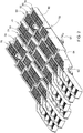
- FIG. 13 shows a perspective view of the straw walker assembly 32. It is seated composed of several (six in the example shown) shakers 66, 68, 70, 72, 74, 76, which are arranged side by side.
- the shakers 66, 68, 70, 72, 74, 76 are all identical and each include horizontal screen linings 78, which are arranged between vertically extending side walls 80, 82, which extend from the screen linings 78 upwards and straight downwards.
- the conveyor floors 84 can also be omitted, since the grain there falls directly onto the rear conveyor floor 42.
- the individual shakers 66, 68, 70, 72, 74, 76 are supported on a front crankshaft 62 and on a rear crankshaft 64 on the frame 12 of the combine harvester 10. At least one of the transverse crankshafts 62 or 64 is connected to the internal combustion engine 58 by a drive train.
- the straw walkers 66, 68, 70, 72, 74, 76 therefore move out of phase with one another (e.g. by 120 °) on circular paths in order to successively transport the straw mat on its upper side up and back and the remaining straw after threshing Separate grain.
- a shaking element 86, 88, 90, 92, 94 is arranged in the spaces between adjacent shakers 66, 68, 70, 72, 74, 76, the shape, attachment and function of which are explained below.
- the shaking elements 86, 88, 90, 92, 94 assume different rotational positions, which depend on the position in which the two adjacent shakers 66, 68, 70, 72, 74, 76 are located.
- the shaking elements 86, 88, 90, 92, 94 are inherently flat so that they fit between the shakers 66, 68, 70, 72, 74, 76 and are each approximately elliptical.
- the shaking elements 86, 88, 90, 92, 94 are attached to the adjacent shakers 66, 68, 70, 72, 74, 76 by means of a rotatable connection with an axis of rotation 108, as in FIG Figures 4 to 6 shown.
- the shaking elements 86, 88, 90, 92, 94 are equipped with thickenings 104 which extend through openings in the side wall 80 or 82 of the adjacent shaker 66, 68, 70, 72, 74, 76.
- a washer 102 rests on the inside of the side wall 80 or 82 at the edge of the opening, through which a screw 100 extends, which extends into the thickening 104 and possibly into the material of the shaking element 86, 88, 90, 92, 94 is screwed in.
- This can be a thread-cutting screw 100 itself or the thread is already present.
- the washer 102 may be made of a low friction material to permit rotation of the Shaking element 86, 88, 90, 92, 94 opposite the shaker 66, 68, 70, 72, 74, 76 to enable.
- the screw connection is replaced by a snap connection, in which a suitable snap-in element 106 is inserted through the opening in the wall 80 or 82 and is locked there by barbs or the like.
- a snap-in connection can also be used between the snap-in element 106 and the shaking element 86, 88, 90, 92, 94.
- the snap-in element also provides a rotatable connection with an axis of rotation 108 between the shaking element 86, 88, 90, 92, 94 and each of the adjacent shakers 66, 68, 70, 72, 74, 76.
- a first of the rotatable connections is preferably designed to be sufficiently stable to fasten the shaking element 86, 88, 90, 92, 94 sufficiently firmly, but rotatably, to the associated shaker 66, 68, 70, 72, 74, 76.
- the second of the rotatable connections does not have to be quite as stable, it only has to transmit the rotary movement. Since tolerances are possible, e.g. in the crankshafts 62, 64 and in the shakers 66, 68, 70, 72, 74, 76, it is conceivable that the second rotatable connection has an axial and / or radial play. The second connection therefore serves more as a guide and less to hold the shaking element 86, 88, 90, 92, 94.
- the Figures 8 to 12 show different possible embodiments of the shaking element 86, 88, 90, 92, 94
- Figure 8 shows a circular, circumferentially toothed shaking element 86, 88, 90, 92, 94
- the Figure 9 shows a circular shaker 86, 88, 90, 92, 94 of smooth circumference.
- the Figures 10 to 12 show oval shaking elements 86, 88, 90, 92, 94, in which in Figures 10 and 11 the circumferential regions spaced apart from the centrally arranged, rotatable connections with the axes of rotation 108 are provided with different toothings and the rest of the circumference is smooth, while in FIG Figure 12 the entire circumference is smooth.
- the shaking elements 86, 88, 90, 92, 94 are each mirror-symmetrical to a first imaginary line of symmetry that runs through the rotatable connections with the axes of rotation 108 and also mirror-symmetrical to a second line of symmetry that is transverse to the first line of symmetry and through the The center point between the rotatable connections with the axes of rotation 108 runs.
- the position of the rotatable connections could, for example, be offset along the second line of symmetry so that the center of the shaking element 86, 88, 90, 92, 94 corresponds to the center 110 of the shaking element 86, 88, 90 , 92, 94 corresponds to the circular movement performed during operation, or any other (contour) shape of the shaking elements 86, 88, 90, 92, 94 can be provided.
- the horizontal and transverse axes of rotation 108 on the side walls 80, 82 of the adjacent shakers 66, 68, 70, 72, 74, 76 are each on the same Place are arranged, ie in the vertical and horizontal directions each in the same position. If the adjacent shakers 66, 68, 70, 72, 74, 76 (without crankshafts 62, 64) are placed next to one another and aligned in the forward direction on the floor, the openings for the axes of rotation assigned to a shaking element 86, 88, 90, 92, 94 are 108 accordingly aligned coaxially in the side walls 80, 82.
- the axes of rotation 108 move on identical circular paths 112 that are only shifted laterally and in phase around coaxial, only laterally offset center points 110 (cf. Figure 12 ), since the shakers 66, 68, 70, 72, 74, 76 are supported on the crankshafts 62, 64. Due to the phase offset of the neighboring shakers 66, 68, 70, 72, 74, 76, the axes of rotation 108 and the shaking elements 86, 88, 90, 92, 94 thus also move on the circular path 112 around the coaxial centers 110, which leads to in the Figure 7 different positions shown.
- the shaking elements 86, 88, 90, 92, 94 run a complete circular path 112 around the center point 110 when the crankshafts 62, 64 rotate 360 °, as in FIGS Figures 7 and 12th shown.
- a relative displacement of the axes of rotation 108 does not take place when the crankshafts 62, 64 are rotated (unlike in the prior art according to FIG DE 1 155 627 A where the axes of rotation 18 and 19 are shown there Figure 1 rotate around different center points, and the pivoting movement of the shaking element 25 present there is replaced by the rotation).
- the shaking elements 86, 88, 90, 92, 94 protrude farthest between the adjacent shakers 66, 68, 70, 72, 74, 76 upwards when these shakers 66, 68, 70, 72, 74, 76 are about are at the same height.
- One of the two shakers 66, 68, 70, 72, 74, 76 is then in the downward movement and the crop above is raised again by the shaking element 86, 88, 90, 92, 94, which is still in the upward movement at a higher speed than the adjacent shaker 66, 68, 70, 72, 74, 76, which is also moving upwards.
- the shaking elements 86, 88, 90, 92, 94 are located with respect to the longitudinal direction of the shaker assembly 32 approximately in the seventh eighth of the shaker assembly 32 and are aligned with one another in the lateral direction. They can also be attached at any other point of the shaker assembly 32 (i.e. further front or rear), or offset in the forward direction in the case of laterally adjacent shaker elements 86, 88, 90, 92, 94, or between adjacent shakers 66, 68, 70, 72, 74, 76 several shaking elements 86, 88, 90, 92, 94 can be arranged one behind the other. There could also be no shaking element 86, 88, 90, 92, 94 between some of the shakers 66, 68, 70, 72, 74, 76.
Landscapes
- Life Sciences & Earth Sciences (AREA)
- Environmental Sciences (AREA)
- Combined Means For Separation Of Solids (AREA)
- Outside Dividers And Delivering Mechanisms For Harvesters (AREA)
- Catching Or Destruction (AREA)
- Harvesting Machines For Specific Crops (AREA)
Description
- Die Erfindung betrifft einen Strohschüttlerzusammenbau für einen Mähdrescher, umfassend:
- eine Anzahl seitlich nebeneinander angeordneter Schüttler, die jeweils einen Siebbelag und an dessen Seiten angeordnete, sich nach oben erstreckende Seitenwände umfassen;
- einen Antrieb, der mit den Schüttlern gekoppelt und eingerichtet ist, die Schüttler zueinander phasenversetzt in eine Bewegung zu versetzen, bei der sie sich entlang einer kreisförmigen Bewegungsbahn bewegen, und
- wenigstens ein zwischen zwei benachbarten Schüttlern angeordnetes Schüttelelement, das durch jeweils eine drehbare Verbindung mit den beiden dem Schüttelelement benachbarten Schüttlern in Antriebsverbindung steht und im Betrieb durch die Schüttler in eine Bewegung versetzbar ist.
- Landwirtschaftliche Mähdrescher sind große Maschinen, die landwirtschaftlich angebautes Erntegut, das Korn trägt, ernten, dreschen, trennen und reinigen. Bei bestimmten Typen von Mähdreschern folgt einem Tangential- oder Mehrtrommeldreschwerk ein Strohschüttlerzusammenbau, um die verbliebenen Körner aus der ausgedroschenen Strohmatte zu separieren.
- Derartige Strohschüttlerzusammenbauten umfassen mehrere, seitlich nebeneinander angeordnete (Horden-) Schüttler, die jeweils einen Siebbelag, durch den die Körner hindurchtreten können, und sich vom Siebbelag nach oben erstreckende Seitenwände aufweisen. Die Schüttler sind mit vorderen und hinteren Kurbelwellen gekoppelt, welche die einzelnen Schüttler jeweils phasenverschoben antreiben. Die Schüttler vollführen demnach eine Bewegung entlang einer Kreisbahn und werfen die Strohmatte periodisch nach oben. Beim anschließenden Aufprall auf den Schüttler werden die Körner aus der Strohmatte herausgelöst.
- Um die Körnerabscheidung des Strohschüttlers zu verbessern, indem die Strohmatte durch mechanische Einwirkung aufgelockert wird, wurden im Stand der Technik verschiedene Maßnahmen vorgeschlagen. Neben oberhalb des Strohschüttlerzusammenbaus angeordneten Förderern (z.B.
DE 70 00 994 U ,DE 25 04 354 A1 ,DD 158 460 A3 DE 24 46 513 A1 ) wurde auch vorgeschlagen, sich mit den Schüttlern mitbewegende, dort mehr oder weniger elastisch angebrachte Elemente zu diesem Zweck zu verwenden (z.B.DE 10 2011 056 607 A1 ,DE 34 41 238 A1 ,DE 81 00 584 U ,DE 82 19 390 U ,DE 36 01 360 A1 ). Die Wirkung dieser Förderer und Elemente ist jedoch begrenzt. - Ein anderer Ansatz besteht darin, zwischen den benachbarten Schüttlern zusätzliche, kammartige Elemente anzubringen, die sich entlang der Schüttler erstrecken und durch separate Kurbelwellen (
DE 24 31 117 A1 ,DE 40 34 852 A1 ) oder direkt oder indirekt durch die zum Antrieb der Schüttler dienende Kurbelwelle angetrieben werden (DE 18 31 439 U ,DE 25 34 206 A1 ). Hier ist der Aufwand für den separaten Antrieb der kammartigen Elemente als nachteilig anzusehen. - In der als gattungsbildend angesehenen
DE 11 55 627 A wird vorgeschlagen, zwischen den Schüttlern angebrachte, zusätzliche Schüttelelemente mit den beiden benachbarten Schüttlern zu koppeln. Dazu wird eine Führungsstange um die Querachse schwenkbar mit dem Boden eines ersten Schüttlers und ebenfalls um die Querachse schwenkbar und axial verschiebbar mit der Oberseite eines zweiten Schüttlers verbunden, der gegenüber dem ersten Schüttler mit einem Phasenversatz von 120° angetrieben wird. Die Führungsstange erstreckt sich demnach nach vorn und oben (oder nach hinten und oben) und trägt an ihrem äußeren, oberen Ende das kammartig ausgebildete und mit Zacken versehene Schüttelelement. Aufgrund dieser Anordnung mit um unterschiedliche Mittelpunkte rotierenden Verbindungspunkten zwischen den Schüttlern und der Führungsstange liegt die Hauptkomponente der Bewegung des Schüttelelements in vertikaler Richtung, was auch beabsichtigt ist, um das Stroh durch Schläge von unten her aufzulockern. Demnach führt das Schüttelelement eine Schwenkbewegung durch und taucht nur für kurze Zeit und einmalig während eines Umlaufs der Kurbelwelle zwischen den beiden Schüttlern ein und befindet sich während der übrigen Zeit oberhalb der benachbarten Schüttler. Er stört daher eher den Gutfluss als dass er die Abscheidung des Strohschüttlerzusammenbaus verbessern würde. - Die der Erfindung zu Grunde liegende Aufgabe wird darin gesehen, einen Strohschüttlerzusammenbau dahingehend zu verbessem, dass die oben erwähnten Nachteile vermieden oder zumindest vermindert werden.
- Die vorliegende Erfindung wird durch die Patentansprüche definiert.
- Ein Strohschüttlerzusammenbau für einen Mähdrescher umfasst eine Anzahl seitlich nebeneinander angeordneter Schüttler, die jeweils einen Siebbelag und an dessen Seiten angeordnete, sich nach oben erstreckende Seitenwände umfassen; einen Antrieb, der mit den Schüttlern gekoppelt und eingerichtet ist, die Schüttler zueinander phasenversetzt in eine Bewegung entlang einer kreisförmigen Bewegungsbahn zu versetzen, und wenigstens ein zwischen zwei benachbarten Schüttlern angeordnetes Schüttelelement, das durch jeweils eine drehbare Verbindung mit den beiden dem Schüttelelement benachbarten Schüttlern in Antriebsverbindung steht und im Betrieb durch die Schüttler in eine Bewegung versetzbar ist. Die drehbaren Verbindungen sind derart an den Schüttlern und am Schüttelelement angeordnet, dass das Schüttelelement in eine Rotationsbewegung um eine Drehachse versetzbar ist.
- Mit anderen Worten wird vorgeschlagen, die Kinematik der Antriebsverbindung zwischen den Schüttlern und dem dazwischen angeordneten Schüttelelement derart zu gestalten, dass letzteres eine vollständige Kreisbewegung um eine Drehachse durchführt (und nicht nur eine Schwenkbewegung, wie im Stand der Technik nach
DE 1 155 627 A vorgesehen). Wenn die Schüttler somit auf ihrer Kreisbahn rotieren, führt auch das Schüttelelement eine Kreisbewegung durch. Da alle Bereiche des Umfangs des Schüttelelements nacheinander mit der Strohmatte in Eingriff gelangen und diese unterschiedlichen Bereiche auch unterschiedlich ausgeformt werden können, ermöglicht die vorgeschlagene Kinematik eine größere Anzahl an Eingriffen in die Strohmatte pro Umlauf der Schüttler, was zu einer verbesserten Abscheidung führt. - Die erwähnte Kreisbewegung des Schüttelelements kann erzielt werden, indem eine erste der Verbindungen an einem ersten der beiden Schüttler an einem ersten Punkt angebracht ist, der sich auf einer Kreisbahn um einen ersten Mittelpunkt bewegt, eine zweite der Verbindungen an einem zweiten der beiden Schüttler an einem zweiten Punkt angebracht ist, der sich auf derselben Kreisbahn um einen zweiten Mittelpunkt bewegt und die beiden Mittelpunkte auf einer gemeinsamen Achse liegen.
- Die Verbindungen können in vertikaler und horizontaler Richtung jeweils in gleicher Lage an den Schüttlern angebracht werden.
- Das Schüttelelement kann zu einer ersten Symmetrielinie, die durch die beiden Verbindungen geht, zumindest näherungsweise spiegelsymmetrisch sein, und/oder zu einer zweiten Symmetrielinie, die quer zur ersten Symmetrielinie und durch den Mittelpunkt zwischen den Verbindungen verläuft, zumindest näherungsweise spiegelsymmetrisch sein. Das Schüttelelement kann entlang der zweiten Symmetrielinie länger als oder gleich lang wie entlang der ersten Symmetrielinie sein.
- Der Umfang des Schüttelelements kann teilweise oder komplett glatt und/oder teilweise oder komplett gezackt sein.
- Die Verbindungen können als Schraub- oder Einschnappverbindung ausgeführt sein.
- In den Zeichnungen sind nachfolgend näher beschriebene Ausführungsbeispiele dargestellt, wobei die Bezugszeichen nicht zu einer einschränkenden Auslegung heranzuziehen sind. Es zeigt:
- Fig. 1
- eine schematische seitliche Ansicht eines Mähdreschers mit einem Tangentialdreschwerk und einem Strohschüttlerzusammenbau,
- Fig. 2
- eine perspektivische Ansicht des Strohschüttlerzusammenbaus,
- Fig. 3
- eine seitliche Ansicht des Strohschüttlerzusammenbaus,
- Fig. 4
- einen horizontalen Schnitt durch die
Figur 3 entlang der Linien 96-96 und 98-98, - Fig. 5
- einen horizontalen Schnitt durch die
Figur 3 entlang der Linien 96-96 und 98-98 in einer anderen Ausführungsform alsFigur 4 , - Fig. 6
- eine Vergrößerung aus
Figur 5 , - Fig. 7
- eine vergrößerte Ansicht der
Figur 3 mit schematisch angedeuteten Schüttelelementen, und - Fig. 8 bis 12
- seitliche Ansichten unterschiedlicher Ausführungsformen der Schüttelelemente.
- Die
Figur 1 zeigt einen selbstfahrenden Mähdrescher 10 mit einem Rahmen 12, der sich über angetriebene vordere Räder 14 und lenkbare rückwärtige Räder 16 auf dem Boden abstützt und von diesen fortbewegt wird. Die Räder 14 werden mittels nicht gezeigter Antriebsmittel in Drehung versetzt, um den Mähdrescher 10 z. B. über ein abzuerntendes Feld zu bewegen. Im Folgenden beziehen sich Richtungsangaben, wie vom und hinten, auf die Fahrtrichtung V des Mähdreschers 10 im Erntebetrieb. - An den vorderen Endbereich des Mähdreschers 10 ist eine Emtegutbergungsvorrichtung 18 in Form eines Schneidwerks abnehmbar angeschlossen, um beim Erntebetrieb Emtegut in Form von Getreide oder andere, dreschbare Halmfrüchten von dem Feld zu ernten und es nach oben und hinten durch einen Schrägförderer 20 einem Mehrtrommeldreschwerk zuzuführen, das - in Fahrtrichtung V hintereinander angeordnet - eine Dreschtrommel 22, eine Abstreiftrommel 24, eine oberschlächtig arbeitende Fördertrommel 26, einen Tangentialseparator 28 sowie eine Wendetrommel 30 umfasst. Stromab der Wendetrommel 30 befindet sich ein Strohschüttlerzusammenbau 32. Die Dreschtrommel 22 ist in ihrem unteren und rückwärtigen Bereich von einem Dreschkorb 34 umgeben. Unterhalb der Fördertrommel 26 ist eine mit Öffnungen versehene oder geschlossene Abdeckung angeordnet, während sich oberhalb der Fördertrommel 26 eine fest stehende Abdeckung und unterhalb des Tangentialseparators 28 ein Separierkorb 36 mit oder ohne verstellbare(n) Fingerelementen befindet. Unterhalb der Wendetrommel 30 ist ein Fingerrechen 38 angeordnet, der auch entfallen könnte.
- Das durch den Dreschkorb 34, den Separierkorb 36 und die Strohschüttler 32 hindurchtretende, Körner und Verunreinigungen enthaltende Gemisch gelangt über Förderböden 40, 42 in eine Reinigungseinrichtung 46. Durch die Reinigungseinrichtung 46 gereinigtes Getreide wird mittels einer Körnerschnecke 48 einem nicht gezeigten Elevator zugeführt, der es in einen Korntank 50 befördert. Eine Überkehrschnecke 52 gibt unausgedroschene Ährenteile durch einen weiteren nicht gezeigten Elevator zurück in den Dreschprozess. Die Spreu kann an der Rückseite der Siebeinrichtung durch einen rotierenden Spreuverteiler ausgeworfen werden, oder sie wird durch einen stromab des Strohschüttlerzusammenbaus 32 angeordneten Strohhäcksler (nicht eingezeichnet) ausgetragen. Das gereinigte Getreide aus dem Korntank 50 kann durch ein Entladesystem mit Querschnecken 54 und einem Entladeförderer 56 entladen werden.
- Die genannten Systeme werden mittels eines Verbrennungsmotors 58 angetrieben und von einem Bediener aus einer Fahrerkabine 60 heraus kontrolliert und gesteuert. Die verschiedenen Vorrichtungen zum Dreschen, Fördern, Reinigen und Abscheiden befinden sich innerhalb des Rahmens 12. Außerhalb des Rahmens 12 befindet sich eine Außenhülle, die größtenteils aufklappbar ist. Es bleibt anzumerken, dass das hier dargestellte Mehrtrommeldreschwerk nur ein Ausführungsbeispiel ist. Es könnte auch durch eine einzige quer angeordnete Dreschtrommel und eine nachgeordnete Trenneinrichtung mit einem Strohschüttlerzusammenbau ersetzt werden.
- Die
Figur 2 zeigt eine perspektivische Ansicht des Strohschüttlerzusammenbaus 32. Er setzt sich aus mehreren (im gezeigten Beispiel sechs) Schüttlem 66, 68, 70, 72, 74, 76 zusammen, die seitlich nebeneinander angeordnet sind. Die Schüttler 66, 68, 70, 72, 74, 76 sind sämtlich baugleich und umfassen jeweils horizontale Siebbeläge 78, die zwischen vertikal verlaufenden Seitenwänden 80, 82 angeordnet sind, die sich von den Siebbelägen 78 zackenförmig nach oben und gerade nach unten erstrecken. An den Unterseiten der Seitenwände 80, 82 befinden sich (jedenfalls im hinteren Bereich des Strohschüttlerzusammenbaus 32) Förderböden 84, die zum Abtransport des abgeschiedenen Koms zum Förderboden 42 dienen. Im vorderen Bereich des Strohschüttlerzusammenbaus 32 können die Förderböden 84 auch entfallen, da das Korn dort direkt auf den rückwärtigen Förderboden 42 fällt. Die einzelnen Schüttler 66, 68, 70, 72, 74, 76 sind an einer vorderen Kurbelwelle 62 und an einer hinteren Kurbelwelle 64 am Rahmen 12 des Mähdreschers 10 abgestützt. Wenigstens eine der quer verlaufenden Kurbelwellen 62 oder 64 ist durch einen Antriebsstrang mit dem Verbrennungsmotor 58 verbunden. Die Strohschüttler 66, 68, 70, 72, 74, 76 bewegen sich demnach jeweils untereinander phasenverschoben (z.B. um 120°) auf Kreisbahnen, um die an ihren Oberseiten liegende Strohmatte sukzessive nach oben und hinten zu transportieren und dabei das nach dem Dreschen darin verbliebene Korn abzuscheiden. - In der
Figur 2 ist auch erkennbar, dass in den Zwischenräumen zwischen benachbarten Schüttlern 66, 68, 70, 72, 74, 76 jeweils ein Schüttelelement 86, 88, 90, 92, 94 angeordnet ist, dessen Form, Anbringung und Funktion im Folgenden erläutert werden. - Wie in den
Figuren 2 ,3 und7 erkennbar, nehmen die Schüttelelemente 86, 88, 90, 92, 94 unterschiedliche Drehstellungen ein, die davon abhängen, in welcher Stellung die beiden benachbarten Schüttler 66, 68, 70, 72, 74, 76 sich jeweils befinden. Die Schüttelelemente 86, 88, 90, 92, 94 sind in der dargestellten Ausführungsform in sich flach, damit sie zwischen die Schüttler 66, 68, 70, 72, 74, 76 passen und jeweils etwa ellipsenförmig. - Die Anbringung der Schüttelelemente 86, 88, 90, 92, 94 an den benachbarten Schüttlern 66, 68, 70, 72, 74, 76 erfolgt durch jeweils eine drehbare Verbindung mit einer Drehachse 108, wie in den
Figuren 4 bis 6 gezeigt. Bei einer ersten Ausführungsform gemäß derFigur 4 sind die Schüttelelemente 86, 88, 90, 92, 94 mit Verdickungen 104 ausgestattet, die sich durch Öffnungen in der Seitenwand 80 oder 82 des benachbarten Schüttlers 66, 68, 70, 72, 74, 76 erstrecken. An der Innenseite der Seitenwand 80 oder 82 liegt am Rand der Öffnung eine Unterlegscheibe 102 an, durch die sich eine Schraube 100 hindurch erstreckt, welche in die Verdickung 104 und ggf. bis in das Material des Schüttelelements 86, 88, 90, 92, 94 eingeschraubt ist. Hierbei kann es sich um selbst ein Gewinde schneidende Schraube 100 handeln oder das Gewinde ist bereits vorhanden. Die Unterlegscheibe 102 kann aus einem reibungsarmen Material sein, um die Drehung des Schüttelelementes 86, 88, 90, 92, 94 gegenüber dem Schüttler 66, 68, 70, 72, 74, 76 zu ermöglichen. - Bei der zweiten Ausführungsform nach
Figur 5 und 6 wird die Schraubverbindung durch eine Einschnappverbindung ersetzt, bei der ein geeignetes Einschnappelement 106 durch die Öffnung der Wand 80 oder 82 gesteckt wird und durch Widerhaken o.ä. dort arretiert ist. Eine derartige Einschnappverbindung kann auch zwischen dem Einschnappelement 106 und dem Schüttelelement 86, 88, 90, 92, 94 verwendet werden. Auch das Einschnappelement stellt eine drehbare Verbindung mit einer Drehachse 108 zwischen dem Schüttelelement 86, 88, 90, 92, 94 und je einem der benachbarten Schüttler 66, 68, 70, 72, 74, 76 bereit. - Bei beiden Ausführungsformen ist vorzugsweise eine erste der drehbaren Verbindungen hinreichend stabil gestaltet, um das Schüttelelement 86, 88, 90, 92, 94 hinreichend fest, aber drehbar, am zugehörigen Schüttler 66, 68, 70, 72, 74, 76 zu befestigen. Die zweite der drehbaren Verbindungen muss nicht ganz so stabil sein, sondern nur die Drehbewegung übertragen. Da Toleranzen möglich sind, z.B. in den Kurbelwellen 62, 64 und in den Schüttlern 66, 68, 70, 72, 74, 76, ist es denkbar, dass die zweite drehbare Verbindung ein axiales und/oder radiales Spiel aufweisen. Die zweite Verbindung dient demnach eher als Führung und weniger zur Halterung des Schüttelelements 86, 88, 90, 92, 94.
- Die
Figuren 8 bis 12 zeigen unterschiedliche, mögliche Ausführungsformen des Schüttelelements 86, 88, 90, 92, 94. DieFigur 8 zeigt ein kreisförmiges, am Umfang verzahntes Schüttelelement 86, 88, 90, 92, 94, während dieFigur 9 ein kreisförmiges Schüttelelement 86, 88, 90, 92, 94 mit glattem Umfang zeigt. DieFiguren 10 bis 12 zeigen ovale Schüttelelemente 86, 88, 90, 92, 94, bei denen inFigur 10 und 11 die von den mittig angeordneten, drehbaren Verbindungen mit den Drehachsen 108 beabstandeten Umfangs-Bereiche mit unterschiedlichen Verzahnungen versehen sind und der Rest des Umfangs glatt ist, während inFigur 12 der gesamte Umfang glatt ist. Die Schüttelelemente 86, 88, 90, 92, 94 sind in den gezeigten Ausführungsformen jeweils spiegelsymmetrisch zu einer ersten gedachten Symmetrielinie, die durch die drehbaren Verbindungen mit den Drehachsen 108 verläuft und auch spiegelsymmetrisch zu einer zweiten Symmetrielinie, die quer zur ersten Symmetrielinie und durch den Mittelpunkt zwischen den drehbaren Verbindungen mit den Drehachsen 108 verläuft. Das muss jedoch nicht notwendigerweise der Fall sein, denn die Lage der drehbaren Verbindungen könnte z.B. entlang der zweiten Symmetrielinie versetzt werden, damit der Mittelpunkt des Schüttelelements 86, 88, 90, 92, 94 mit dem Mittelpunkt 110 der vom Schüttelelement 86, 88, 90, 92, 94 im Betrieb vollführten Kreisbewegung übereinstimmt, oder eine beliebige andere (Umriss-) Form der Schüttelelemente 86, 88, 90, 92, 94 kann vorgesehen sein. - Zur Erläuterung der Funktion der Schüttelelemente 86, 88, 90, 92, 94 ist anzumerken, dass die horizontal und quer verlaufenden Drehachsen 108 an den Seitenwänden 80, 82 der benachbarten Schüttlern 66, 68, 70, 72, 74, 76 jeweils an der gleichen Stelle angeordnet sind, d.h. in vertikaler und horizontaler Richtung jeweils in derselben Position. Legt man die benachbarten Schüttler 66, 68, 70, 72, 74, 76 (ohne Kurbelwellen 62, 64) nebeneinander und in Vorwärtsrichtung ausgerichtet auf den Boden, sind die einem Schüttelelement 86, 88, 90, 92, 94 zugeordneten Öffnungen für die Drehachsen 108 in den Seitenwänden 80, 82 demnach koaxial ausgerichtet. Im Betrieb bewegen sich die Drehachsen 108 auf identischen, nur seitlich und in der Phase verschobenen Kreisbahnen 112 um koaxiale, nur seitlich versetzte Mittelpunkte 110 (vgl.
Figur 12 ), da die Schüttler 66, 68, 70, 72, 74, 76 an den Kurbelwellen 62, 64 abgestützt sind. Durch den Phasenversatz der benachbarten Schüttler 66, 68, 70, 72, 74, 76 bedingt, bewegen sich die Drehachsen 108 und die Schüttelelemente 86, 88, 90, 92, 94 somit ebenfalls auf der Kreisbahn 112 um die koaxialen Mittelpunkte 110, was zu den in derFigur 7 gezeigten, unterschiedlichen Positionen führt. Da die beiden Drehachsen 108 sich auf identischen (nur phasenverschobenen) Kreisbahnen 112 um den auf einer gemeinsamen, quer verlaufenden Achse liegenden Mittelpunkt 110 drehen, laufen die Schüttelelemente 86, 88, 90, 92, 94 eine komplette Kreisbahn 112 um den Mittelpunkt 110, wenn sich die Kurbelwellen 62, 64 um 360° drehen, wie in denFiguren 7 und12 gezeigt. Eine Relativverschiebung der Drehachsen 108 findet beim Drehen der Kurbelwellen 62, 64 nicht statt (anders als im Stand der Technik nachDE 1 155 627 A , wo die Drehachsen 18 und 19 der dort gezeigtenFigur 1 um unterschiedliche Mittelpunkte rotieren, und die dort vorhandene Schwenkbewegung des Schüttelelements 25 wird durch die Drehung ersetzt). - Wie in den
Figuren 2 ,3 , und7 erkennbar, ragen die Schüttelelemente 86, 88, 90, 92, 94 am weitesten zwischen den benachbarten Schüttlern 66, 68, 70, 72, 74, 76 nach oben, wenn diese Schüttler 66, 68, 70, 72, 74, 76 sich etwa in derselben Höhe befinden. Einer der beiden Schüttler 66, 68, 70, 72, 74, 76 befindet sich dann in der Abwärtsbewegung und das darüber befindliche Emtegut wird durch das Schüttelelement 86, 88, 90, 92, 94, das sich noch in der Aufwärtsbewegung befindet, wieder angehoben, und zwar mit einer höheren Geschwindigkeit als sie der benachbarte, auch in der Aufwärtsbewegung befindliche Schüttler 66, 68, 70, 72, 74, 76 durchführt. Auf diese Weise erreicht man, dass die Strohmatte effektiv und mit einfachen Mitteln aufgelockert wird. Es wäre jedoch möglich, andere Zeitabstimmungen (Verhältnisse zwischen Drehwinkel der Schüttler 66, 68, 70, 72, 74, 76 und Schüttelelemente 86, 88, 90, 92, 94) zu wählen, z.B. die Schüttelelemente 86, 88, 90, 92, 94 horizontal zu stellen, wenn die benachbarten Schüttler 66, 68, 70, 72, 74, 76 in einer gemeinsamen Ebene liegen. Hierzu wären die Positionierungen der Drehachsen 108 an den Schüttelelementen 86, 88, 90, 92, 94 anzupassen. - Bei der dargestellten Ausführungsform befinden sich die Schüttelelemente 86, 88, 90, 92, 94 bezüglich der Längsrichtung des Schüttlerzusammenbaus 32 etwa im siebten Achtel des Schüttlerzusammenbaus 32 und sind in seitlicher Richtung miteinander ausgerichtet. Sie können auch an beliebiger anderer Stelle des Schüttlerzusammenbaus 32 (d.h. weiter vorn oder hinten) angebracht werden, oder bei seitlich benachbarten Schüttelelementen 86, 88, 90, 92, 94 in Vorwärtsrichtung versetzt, oder zwischen benachbarten Schüttlern 66, 68, 70, 72, 74, 76 können hintereinander mehrere Schüttelelemente 86, 88, 90, 92, 94 angeordnet sein. Auch könnte zwischen einigen der Schüttler 66, 68, 70, 72, 74, 76 kein Schüttelelement 86, 88, 90, 92, 94 sein.
Claims (9)
- Strohschüttlerzusammenbau (32) für einen Mähdrescher (10), umfassend:eine Anzahl seitlich nebeneinander angeordneter Schüttler (66, 68, 70, 72, 74, 76), die jeweils einen Siebbelag (78) und an dessen Seiten angeordnete, sich nach oben erstreckende Seitenwände (80, 82) umfassen;einen Antrieb, der mit den Schüttlern (66, 68, 70, 72, 74, 76) gekoppelt und eingerichtet ist, die Schüttler (66, 68, 70, 72, 74, 76) zueinander phasenversetzt in eine Bewegung zu versetzen, bei der sie sich entlang einer kreisförmigen Bewegungsbahn bewegen, undwenigstens ein zwischen zwei benachbarten Schüttlern (66, 68, 70, 72, 74, 76) angeordnetes Schüttelelement (86, 88, 90, 92, 94), das durch jeweils eine drehbare Verbindung mit einer Drehachse (108) mit den beiden dem Schüttelelement (86, 88, 90, 92, 94) benachbarten Schüttlern (66, 68, 70, 72, 74, 76) in Antriebsverbindung steht und im Betrieb durch die Schüttler (66, 68, 70, 72, 74, 76) in eine Bewegung versetzbar ist,dadurch gekennzeichnet, dass die drehbaren Verbindungen derart an den Schüttlern (66, 68, 70, 72, 74, 76) und am Schüttelelement (86, 88, 90, 92, 94) angeordnet sind, dass das Schüttelelement (86, 88, 90, 92, 94) in eine Rotationsbewegung um eine Drehachse versetzbar ist.
- Strohschüttlerzusammenbau (32) nach Anspruch 1, wobei eine erste der Verbindungen an einem ersten der beiden Schüttler (66, 68, 70, 72, 74, 76) an einem ersten Punkt angebracht ist, der sich auf einer Kreisbahn (112) um einen ersten Mittelpunkt (110) bewegt, eine zweite der Verbindungen an einem zweiten der beiden Schüttler (66, 68, 70, 72, 74, 76) an einem zweiten Punkt angebracht ist, der sich auf derselben Kreisbahn (112) um einen zweiten Mittelpunkt (110) bewegt und die beiden Mittelpunkte (110) auf einer gemeinsamen Achse liegen.
- Strohschüttlerzusammenbau (32) nach Anspruch 2, wobei die Verbindungen in vertikaler und horizontaler Richtung jeweils in gleicher Lage an den Schüttlern (66, 68, 70, 72, 74, 76) angebracht sind.
- Strohschüttlerzusammenbau (32) nach einem der Ansprüche 1 bis 3, wobei das Schüttelelement (86, 88, 90, 92, 94) zu einer ersten Symmetrielinie, die durch die beiden Verbindungen geht, zumindest näherungsweise spiegelsymmetrisch ist.
- Strohschüttlerzusammenbau (32) nach Anspruch 4, wobei das Schüttelelement (86, 88, 90, 92, 94) zu einer zweiten Symmetrielinie, die quer zur ersten Symmetrielinie und durch den Mittelpunkt zwischen den Verbindungen verläuft, zumindest näherungsweise spiegelsymmetrisch ist.
- Strohschüttlerzusammenbau (32) nach Anspruch 5, wobei das Schüttelelement (86, 88, 90, 92, 94) entlang der zweiten Symmetrielinie länger als oder gleich lang wie entlang der ersten Symmetrielinie ist.
- Strohschüttlerzusammenbau (32) nach einem der vorhergehenden Ansprüche, wobei der Umfang des Schüttelelements (86, 88, 90, 92, 94) teilweise oder komplett glatt und/oder teilweise oder komplett gezackt ist.
- Strohschüttlerzusammenbau (32) nach der vorhergehenden Ansprüche, wobei die Verbindungen als Schraub- oder Einschnappverbindung ausgeführt sind.
- Mähdrescher (10) mit einem Schüttlerzusammenbau (32) nach einem der vorhergehenden Ansprüche.
Applications Claiming Priority (1)
| Application Number | Priority Date | Filing Date | Title |
|---|---|---|---|
| DE102018221418.2A DE102018221418A1 (de) | 2018-12-11 | 2018-12-11 | Strohschüttlerzusammenbau für einen Mähdrescher |
Publications (2)
| Publication Number | Publication Date |
|---|---|
| EP3666060A1 EP3666060A1 (de) | 2020-06-17 |
| EP3666060B1 true EP3666060B1 (de) | 2021-10-20 |
Family
ID=68847987
Family Applications (1)
| Application Number | Title | Priority Date | Filing Date |
|---|---|---|---|
| EP19214717.1A Active EP3666060B1 (de) | 2018-12-11 | 2019-12-10 | Strohschüttlerzusammenbau für einen mähdrescher |
Country Status (3)
| Country | Link |
|---|---|
| EP (1) | EP3666060B1 (de) |
| CN (1) | CN111296078B (de) |
| DE (1) | DE102018221418A1 (de) |
Families Citing this family (1)
| Publication number | Priority date | Publication date | Assignee | Title |
|---|---|---|---|---|
| US11997953B2 (en) * | 2018-11-06 | 2024-06-04 | Jakob Sørensen Ip Aps | Grain separating apparatus for a combine harvester and a method for separating grain from straw material |
Family Cites Families (25)
| Publication number | Priority date | Publication date | Assignee | Title |
|---|---|---|---|---|
| GB706396A (en) * | 1950-03-21 | 1954-03-31 | Claude William Howlett | Improvements in or relating to agricultural machinery |
| DE1831439U (de) | 1960-08-19 | 1961-05-18 | Josef Bautz G M B H | Hordenschuettler fuer maehmaschinen, insbesondere maehdrescher. |
| DE1155627B (de) | 1962-04-27 | 1963-10-10 | John Deere Lanz Ag | Hordenschuettler fuer Dreschmaschinen, insbesondere fuer Maehdrescher |
| DE7000994U (de) | 1970-01-14 | 1974-04-25 | Deere & Co | Vorrichtung zum verteilen und lockern des aus der dreschvorrichtung eines maehdreschers anfallenden gutes. |
| DE2426731A1 (de) * | 1974-06-01 | 1975-12-11 | Claas Maschf Gmbh Geb | Vorrichtung zum verteilen und auflockern der von den hordenschuettlern eines maehdreschers bewegten strohmatte |
| DE2431117C3 (de) | 1974-06-28 | 1979-09-20 | Gebr. Claas Maschinenfabrik Gmbh, 4834 Harsewinkel | Vorrichtung zum Verteilen und Auf-Iockern des aus der Dreschvorrichtung eines Mähdreschers ausgeworfenen Gutes |
| DE2446513A1 (de) | 1974-09-28 | 1976-04-15 | Claas Maschf Gmbh Geb | Vorrichtung zum auflockern der strohmatte von maehdreschern |
| IT1024637B (it) * | 1974-10-18 | 1978-07-20 | Laverda P S P A | Dispositivo per il ricupero della granella dagli scuotipaglia di macchine mietitrebbiatrici |
| DE2504354C3 (de) | 1975-02-03 | 1980-09-25 | Maschinenfabrik Fahr Ag Gottmadingen, 7702 Gottmadingen | Vorrichtung zum Verteilen und Lockern des aus der Dreschvorrichtung eines Mähdreschers anfallenden Gutes |
| DE3020811A1 (de) * | 1980-06-02 | 1981-12-10 | Deere & Co., Niederlassung Deere & Co. European Office 6800 Mannheim, Moline, Ill. | Gekroepfte schuettlerwelle fuer maehdrescher |
| DE8100584U1 (de) | 1981-01-14 | 1981-05-21 | Claas Ohg, 4834 Harsewinkel | Hordenschüttler für Mähdrescher |
| DD158460A3 (de) | 1981-04-02 | 1983-01-19 | Johann Rumpler | Lockerungs-und verteilvorrichtung an strohschuettlern |
| DD222193A1 (de) | 1983-12-20 | 1985-05-15 | Fortschritt Veb K | Vorrichtung zur intensivierung der koernerabscheidung |
| DE3601360A1 (de) | 1986-01-18 | 1987-07-23 | Claas Ohg | Vorrichtung zur auflockerung der strohmatte von maehdreschern |
| DE3907836A1 (de) * | 1989-03-10 | 1990-09-13 | Johannes Hillmann | Schuettler, insbesondere fuer einen maehdrescher |
| DE4034852A1 (de) | 1990-11-02 | 1992-05-07 | Bayerische Motoren Werke Ag | Anschlussventil fuer hydraulische antriebe |
| US5305891A (en) * | 1990-12-19 | 1994-04-26 | Beloit Technologies, Inc. | Wood chip bar screen deck arrangement |
| CN201839637U (zh) * | 2010-10-20 | 2011-05-25 | 新疆中收农牧机械公司 | 收割机抖动板分层预清选装置 |
| BRPI1103280A2 (pt) * | 2011-07-06 | 2013-07-23 | Lcp Engenharia Ltda | sistema de posicionamento para bandeja vibratària de mÁquinas despalhadores |
| DE102011056607A1 (de) | 2011-12-19 | 2013-06-20 | Claas Selbstfahrende Erntemaschinen Gmbh | Abscheidevorrichtung für einen Mähdrescher |
| BE1021121B1 (nl) * | 2013-01-03 | 2016-02-15 | Cnh Industrial Belgium Nv | Een oogstmachine bevattende een stroschudderbesturingssysteem |
| CN103392454B (zh) * | 2013-07-02 | 2015-04-08 | 河北科技大学 | 连翘脱粒碎枝机 |
| US9226450B2 (en) * | 2013-09-20 | 2016-01-05 | Deere & Company | Lightweight hybrid material reciprocating sieve |
| BE1023017B1 (nl) * | 2015-06-30 | 2016-11-04 | Cnh Industrial Belgium Nv | Maaidorser met stroschudders met verstelbare helling |
| CN108355956B (zh) * | 2018-05-13 | 2023-10-03 | 吉林大学 | 气吹推抛耦合式谷物高效分离逐稿装置 |
-
2018
- 2018-12-11 DE DE102018221418.2A patent/DE102018221418A1/de not_active Withdrawn
-
2019
- 2019-12-10 EP EP19214717.1A patent/EP3666060B1/de active Active
- 2019-12-11 CN CN201911265305.4A patent/CN111296078B/zh active Active
Also Published As
| Publication number | Publication date |
|---|---|
| EP3666060A1 (de) | 2020-06-17 |
| CN111296078A (zh) | 2020-06-19 |
| CN111296078B (zh) | 2022-11-25 |
| DE102018221418A1 (de) | 2020-06-18 |
Similar Documents
| Publication | Publication Date | Title |
|---|---|---|
| DE2628414C2 (de) | ||
| DE2000553C3 (de) | ||
| EP2594126B1 (de) | Abscheidekorb | |
| EP1228683B1 (de) | Mähdrescher mit einem Rotationsförderer | |
| DE2433948A1 (de) | Ernte- und dreschmaschine | |
| DE2245603A1 (de) | Vorschubvorrichtung fuer maehdrescher | |
| DE102013226436B4 (de) | Schrägförderer für einen Mähdrescher | |
| EP3228174A1 (de) | Wurfrotor einer gutverteileinrichtung für eine selbstfahrende erntemaschine | |
| EP2036425B2 (de) | Dreschkorbanordnung für einen Mähdrescher | |
| DE2413975C2 (de) | Kornabschneider, z.B. für Mähdrescher | |
| DE10314081B4 (de) | Austrageinrichtung zum Austragen von Erntegut aus einer Erntemaschine | |
| EP3666060B1 (de) | Strohschüttlerzusammenbau für einen mähdrescher | |
| EP2596696B1 (de) | Mähdrescher mit einer als Mehrtrommelanordnung ausgebildeten Dresch- und Trenneinrichtung | |
| DE102004004495A1 (de) | Dreschwerk für Mähdrescher | |
| EP1354508B1 (de) | Axialabscheider mit Leitschiene | |
| EP1579755B1 (de) | Strohleitrechen | |
| BE1020777A3 (de) | Strohschüttleranordnung für einen mähdrescher. | |
| DE19709396A1 (de) | Mähdrescher | |
| EP3150058B1 (de) | Mähdrescher | |
| EP0836373B1 (de) | Landwirtschaftliche erntemaschine | |
| DE102011088543B4 (de) | Mähdrescher mit einer zwischen der Drescheinrichtung und der Reinigung angeordneten Nachdrescheinrichtung | |
| EP1864566B1 (de) | Mähdrescher mit einer Körner abscheidenden Fördereinrichtung zwischen der Reinigungseinrichtung und einem Abgabeförderer für Spreu | |
| EP1495668B1 (de) | Axialtrenneinrichtung | |
| DE102006007810A1 (de) | Mähdrescher mit mehrstufigem Trennbereich | |
| DE102006007809A1 (de) | Mähdrescher mit mehrstufigem Trennbereich |
Legal Events
| Date | Code | Title | Description |
|---|---|---|---|
| PUAI | Public reference made under article 153(3) epc to a published international application that has entered the european phase |
Free format text: ORIGINAL CODE: 0009012 |
|
| STAA | Information on the status of an ep patent application or granted ep patent |
Free format text: STATUS: THE APPLICATION HAS BEEN PUBLISHED |
|
| AK | Designated contracting states |
Kind code of ref document: A1 Designated state(s): AL AT BE BG CH CY CZ DE DK EE ES FI FR GB GR HR HU IE IS IT LI LT LU LV MC MK MT NL NO PL PT RO RS SE SI SK SM TR |
|
| AX | Request for extension of the european patent |
Extension state: BA ME |
|
| STAA | Information on the status of an ep patent application or granted ep patent |
Free format text: STATUS: REQUEST FOR EXAMINATION WAS MADE |
|
| 17P | Request for examination filed |
Effective date: 20201217 |
|
| RBV | Designated contracting states (corrected) |
Designated state(s): AL AT BE BG CH CY CZ DE DK EE ES FI FR GB GR HR HU IE IS IT LI LT LU LV MC MK MT NL NO PL PT RO RS SE SI SK SM TR |
|
| GRAP | Despatch of communication of intention to grant a patent |
Free format text: ORIGINAL CODE: EPIDOSNIGR1 |
|
| STAA | Information on the status of an ep patent application or granted ep patent |
Free format text: STATUS: GRANT OF PATENT IS INTENDED |
|
| INTG | Intention to grant announced |
Effective date: 20210608 |
|
| RIN1 | Information on inventor provided before grant (corrected) |
Inventor name: BISCHOFF, LUTZ Inventor name: LAUER, FRIEDRICH Inventor name: NARLAWAR, TUSHAR |
|
| GRAS | Grant fee paid |
Free format text: ORIGINAL CODE: EPIDOSNIGR3 |
|
| GRAA | (expected) grant |
Free format text: ORIGINAL CODE: 0009210 |
|
| STAA | Information on the status of an ep patent application or granted ep patent |
Free format text: STATUS: THE PATENT HAS BEEN GRANTED |
|
| AK | Designated contracting states |
Kind code of ref document: B1 Designated state(s): AL AT BE BG CH CY CZ DE DK EE ES FI FR GB GR HR HU IE IS IT LI LT LU LV MC MK MT NL NO PL PT RO RS SE SI SK SM TR |
|
| REG | Reference to a national code |
Ref country code: GB Ref legal event code: FG4D Free format text: NOT ENGLISH |
|
| REG | Reference to a national code |
Ref country code: CH Ref legal event code: EP |
|
| REG | Reference to a national code |
Ref country code: DE Ref legal event code: R096 Ref document number: 502019002549 Country of ref document: DE |
|
| REG | Reference to a national code |
Ref country code: IE Ref legal event code: FG4D Free format text: LANGUAGE OF EP DOCUMENT: GERMAN |
|
| REG | Reference to a national code |
Ref country code: AT Ref legal event code: REF Ref document number: 1439153 Country of ref document: AT Kind code of ref document: T Effective date: 20211115 |
|
| REG | Reference to a national code |
Ref country code: LT Ref legal event code: MG9D |
|
| REG | Reference to a national code |
Ref country code: NL Ref legal event code: MP Effective date: 20211020 |
|
| PG25 | Lapsed in a contracting state [announced via postgrant information from national office to epo] |
Ref country code: RS Free format text: LAPSE BECAUSE OF FAILURE TO SUBMIT A TRANSLATION OF THE DESCRIPTION OR TO PAY THE FEE WITHIN THE PRESCRIBED TIME-LIMIT Effective date: 20211020 Ref country code: LT Free format text: LAPSE BECAUSE OF FAILURE TO SUBMIT A TRANSLATION OF THE DESCRIPTION OR TO PAY THE FEE WITHIN THE PRESCRIBED TIME-LIMIT Effective date: 20211020 Ref country code: FI Free format text: LAPSE BECAUSE OF FAILURE TO SUBMIT A TRANSLATION OF THE DESCRIPTION OR TO PAY THE FEE WITHIN THE PRESCRIBED TIME-LIMIT Effective date: 20211020 Ref country code: BG Free format text: LAPSE BECAUSE OF FAILURE TO SUBMIT A TRANSLATION OF THE DESCRIPTION OR TO PAY THE FEE WITHIN THE PRESCRIBED TIME-LIMIT Effective date: 20220120 |
|
| PG25 | Lapsed in a contracting state [announced via postgrant information from national office to epo] |
Ref country code: IS Free format text: LAPSE BECAUSE OF FAILURE TO SUBMIT A TRANSLATION OF THE DESCRIPTION OR TO PAY THE FEE WITHIN THE PRESCRIBED TIME-LIMIT Effective date: 20220220 Ref country code: SE Free format text: LAPSE BECAUSE OF FAILURE TO SUBMIT A TRANSLATION OF THE DESCRIPTION OR TO PAY THE FEE WITHIN THE PRESCRIBED TIME-LIMIT Effective date: 20211020 Ref country code: PT Free format text: LAPSE BECAUSE OF FAILURE TO SUBMIT A TRANSLATION OF THE DESCRIPTION OR TO PAY THE FEE WITHIN THE PRESCRIBED TIME-LIMIT Effective date: 20220221 Ref country code: PL Free format text: LAPSE BECAUSE OF FAILURE TO SUBMIT A TRANSLATION OF THE DESCRIPTION OR TO PAY THE FEE WITHIN THE PRESCRIBED TIME-LIMIT Effective date: 20211020 Ref country code: NO Free format text: LAPSE BECAUSE OF FAILURE TO SUBMIT A TRANSLATION OF THE DESCRIPTION OR TO PAY THE FEE WITHIN THE PRESCRIBED TIME-LIMIT Effective date: 20220120 Ref country code: NL Free format text: LAPSE BECAUSE OF FAILURE TO SUBMIT A TRANSLATION OF THE DESCRIPTION OR TO PAY THE FEE WITHIN THE PRESCRIBED TIME-LIMIT Effective date: 20211020 Ref country code: LV Free format text: LAPSE BECAUSE OF FAILURE TO SUBMIT A TRANSLATION OF THE DESCRIPTION OR TO PAY THE FEE WITHIN THE PRESCRIBED TIME-LIMIT Effective date: 20211020 Ref country code: HR Free format text: LAPSE BECAUSE OF FAILURE TO SUBMIT A TRANSLATION OF THE DESCRIPTION OR TO PAY THE FEE WITHIN THE PRESCRIBED TIME-LIMIT Effective date: 20211020 Ref country code: GR Free format text: LAPSE BECAUSE OF FAILURE TO SUBMIT A TRANSLATION OF THE DESCRIPTION OR TO PAY THE FEE WITHIN THE PRESCRIBED TIME-LIMIT Effective date: 20220121 Ref country code: ES Free format text: LAPSE BECAUSE OF FAILURE TO SUBMIT A TRANSLATION OF THE DESCRIPTION OR TO PAY THE FEE WITHIN THE PRESCRIBED TIME-LIMIT Effective date: 20211020 |
|
| REG | Reference to a national code |
Ref country code: DE Ref legal event code: R097 Ref document number: 502019002549 Country of ref document: DE |
|
| PG25 | Lapsed in a contracting state [announced via postgrant information from national office to epo] |
Ref country code: SM Free format text: LAPSE BECAUSE OF FAILURE TO SUBMIT A TRANSLATION OF THE DESCRIPTION OR TO PAY THE FEE WITHIN THE PRESCRIBED TIME-LIMIT Effective date: 20211020 Ref country code: SK Free format text: LAPSE BECAUSE OF FAILURE TO SUBMIT A TRANSLATION OF THE DESCRIPTION OR TO PAY THE FEE WITHIN THE PRESCRIBED TIME-LIMIT Effective date: 20211020 Ref country code: RO Free format text: LAPSE BECAUSE OF FAILURE TO SUBMIT A TRANSLATION OF THE DESCRIPTION OR TO PAY THE FEE WITHIN THE PRESCRIBED TIME-LIMIT Effective date: 20211020 Ref country code: MC Free format text: LAPSE BECAUSE OF FAILURE TO SUBMIT A TRANSLATION OF THE DESCRIPTION OR TO PAY THE FEE WITHIN THE PRESCRIBED TIME-LIMIT Effective date: 20211020 Ref country code: EE Free format text: LAPSE BECAUSE OF FAILURE TO SUBMIT A TRANSLATION OF THE DESCRIPTION OR TO PAY THE FEE WITHIN THE PRESCRIBED TIME-LIMIT Effective date: 20211020 Ref country code: DK Free format text: LAPSE BECAUSE OF FAILURE TO SUBMIT A TRANSLATION OF THE DESCRIPTION OR TO PAY THE FEE WITHIN THE PRESCRIBED TIME-LIMIT Effective date: 20211020 Ref country code: CZ Free format text: LAPSE BECAUSE OF FAILURE TO SUBMIT A TRANSLATION OF THE DESCRIPTION OR TO PAY THE FEE WITHIN THE PRESCRIBED TIME-LIMIT Effective date: 20211020 |
|
| PLBE | No opposition filed within time limit |
Free format text: ORIGINAL CODE: 0009261 |
|
| STAA | Information on the status of an ep patent application or granted ep patent |
Free format text: STATUS: NO OPPOSITION FILED WITHIN TIME LIMIT |
|
| 26N | No opposition filed |
Effective date: 20220721 |
|
| PG25 | Lapsed in a contracting state [announced via postgrant information from national office to epo] |
Ref country code: LU Free format text: LAPSE BECAUSE OF NON-PAYMENT OF DUE FEES Effective date: 20211210 Ref country code: IE Free format text: LAPSE BECAUSE OF NON-PAYMENT OF DUE FEES Effective date: 20211210 Ref country code: AL Free format text: LAPSE BECAUSE OF FAILURE TO SUBMIT A TRANSLATION OF THE DESCRIPTION OR TO PAY THE FEE WITHIN THE PRESCRIBED TIME-LIMIT Effective date: 20211020 |
|
| PG25 | Lapsed in a contracting state [announced via postgrant information from national office to epo] |
Ref country code: SI Free format text: LAPSE BECAUSE OF FAILURE TO SUBMIT A TRANSLATION OF THE DESCRIPTION OR TO PAY THE FEE WITHIN THE PRESCRIBED TIME-LIMIT Effective date: 20211020 Ref country code: FR Free format text: LAPSE BECAUSE OF NON-PAYMENT OF DUE FEES Effective date: 20211220 |
|
| PG25 | Lapsed in a contracting state [announced via postgrant information from national office to epo] |
Ref country code: IT Free format text: LAPSE BECAUSE OF FAILURE TO SUBMIT A TRANSLATION OF THE DESCRIPTION OR TO PAY THE FEE WITHIN THE PRESCRIBED TIME-LIMIT Effective date: 20211020 |
|
| PG25 | Lapsed in a contracting state [announced via postgrant information from national office to epo] |
Ref country code: CY Free format text: LAPSE BECAUSE OF FAILURE TO SUBMIT A TRANSLATION OF THE DESCRIPTION OR TO PAY THE FEE WITHIN THE PRESCRIBED TIME-LIMIT Effective date: 20211020 |
|
| PG25 | Lapsed in a contracting state [announced via postgrant information from national office to epo] |
Ref country code: HU Free format text: LAPSE BECAUSE OF FAILURE TO SUBMIT A TRANSLATION OF THE DESCRIPTION OR TO PAY THE FEE WITHIN THE PRESCRIBED TIME-LIMIT; INVALID AB INITIO Effective date: 20191210 |
|
| REG | Reference to a national code |
Ref country code: CH Ref legal event code: PL |
|
| PG25 | Lapsed in a contracting state [announced via postgrant information from national office to epo] |
Ref country code: CH Free format text: LAPSE BECAUSE OF NON-PAYMENT OF DUE FEES Effective date: 20221231 Ref country code: LI Free format text: LAPSE BECAUSE OF NON-PAYMENT OF DUE FEES Effective date: 20221231 |
|
| PG25 | Lapsed in a contracting state [announced via postgrant information from national office to epo] |
Ref country code: MK Free format text: LAPSE BECAUSE OF FAILURE TO SUBMIT A TRANSLATION OF THE DESCRIPTION OR TO PAY THE FEE WITHIN THE PRESCRIBED TIME-LIMIT Effective date: 20211020 |
|
| GBPC | Gb: european patent ceased through non-payment of renewal fee |
Effective date: 20231210 |
|
| PG25 | Lapsed in a contracting state [announced via postgrant information from national office to epo] |
Ref country code: MT Free format text: LAPSE BECAUSE OF FAILURE TO SUBMIT A TRANSLATION OF THE DESCRIPTION OR TO PAY THE FEE WITHIN THE PRESCRIBED TIME-LIMIT Effective date: 20211020 |
|
| PG25 | Lapsed in a contracting state [announced via postgrant information from national office to epo] |
Ref country code: GB Free format text: LAPSE BECAUSE OF NON-PAYMENT OF DUE FEES Effective date: 20231210 |
|
| PG25 | Lapsed in a contracting state [announced via postgrant information from national office to epo] |
Ref country code: GB Free format text: LAPSE BECAUSE OF NON-PAYMENT OF DUE FEES Effective date: 20231210 |
|
| PGFP | Annual fee paid to national office [announced via postgrant information from national office to epo] |
Ref country code: BE Payment date: 20241227 Year of fee payment: 6 |
|
| PG25 | Lapsed in a contracting state [announced via postgrant information from national office to epo] |
Ref country code: TR Free format text: LAPSE BECAUSE OF FAILURE TO SUBMIT A TRANSLATION OF THE DESCRIPTION OR TO PAY THE FEE WITHIN THE PRESCRIBED TIME-LIMIT Effective date: 20211020 |
|
| PGFP | Annual fee paid to national office [announced via postgrant information from national office to epo] |
Ref country code: DE Payment date: 20251119 Year of fee payment: 7 |
|
| REG | Reference to a national code |
Ref country code: AT Ref legal event code: MM01 Ref document number: 1439153 Country of ref document: AT Kind code of ref document: T Effective date: 20241210 |
|
| PG25 | Lapsed in a contracting state [announced via postgrant information from national office to epo] |
Ref country code: AT Free format text: LAPSE BECAUSE OF NON-PAYMENT OF DUE FEES Effective date: 20241210 |
|
| PGFP | Annual fee paid to national office [announced via postgrant information from national office to epo] |
Ref country code: AT Payment date: 20260410 Year of fee payment: 5 |