EP3666121A1 - Dispositif de raccordement de l'avant de tiroir et tiroir - Google Patents
Dispositif de raccordement de l'avant de tiroir et tiroir Download PDFInfo
- Publication number
- EP3666121A1 EP3666121A1 EP19206413.7A EP19206413A EP3666121A1 EP 3666121 A1 EP3666121 A1 EP 3666121A1 EP 19206413 A EP19206413 A EP 19206413A EP 3666121 A1 EP3666121 A1 EP 3666121A1
- Authority
- EP
- European Patent Office
- Prior art keywords
- drawer
- connector
- ramp
- support section
- connecting device
- Prior art date
- Legal status (The legal status is an assumption and is not a legal conclusion. Google has not performed a legal analysis and makes no representation as to the accuracy of the status listed.)
- Granted
Links
Images


Classifications
-
- A—HUMAN NECESSITIES
- A47—FURNITURE; DOMESTIC ARTICLES OR APPLIANCES; COFFEE MILLS; SPICE MILLS; SUCTION CLEANERS IN GENERAL
- A47B—TABLES; DESKS; OFFICE FURNITURE; CABINETS; DRAWERS; GENERAL DETAILS OF FURNITURE
- A47B88/00—Drawers for tables, cabinets or like furniture; Guides for drawers
- A47B88/90—Constructional details of drawers
- A47B88/944—Drawers characterised by the front panel
- A47B88/95—Drawers characterised by the front panel characterised by connection means for the front panel
- A47B88/956—Drawers characterised by the front panel characterised by connection means for the front panel for enabling adjustment of the front panel
-
- A—HUMAN NECESSITIES
- A47—FURNITURE; DOMESTIC ARTICLES OR APPLIANCES; COFFEE MILLS; SPICE MILLS; SUCTION CLEANERS IN GENERAL
- A47B—TABLES; DESKS; OFFICE FURNITURE; CABINETS; DRAWERS; GENERAL DETAILS OF FURNITURE
- A47B88/00—Drawers for tables, cabinets or like furniture; Guides for drawers
- A47B88/90—Constructional details of drawers
- A47B88/944—Drawers characterised by the front panel
- A47B88/95—Drawers characterised by the front panel characterised by connection means for the front panel
- A47B2088/951—Drawers characterised by the front panel characterised by connection means for the front panel having male and female interlocking parts
Definitions
- drawer In the furniture sector, furniture with a drawer is known, the drawer being movable relative to a body and a drawer front component being attached to the drawer side parts via a drawer front connecting device.
- the drawer front is preferably detachably or interchangeably attachable to the two drawer side parts.
- Previous drawer front connecting devices are also complicated to manufacture or have many parts and require a comparatively large installation space on the respective drawer side part, so that satisfactory solutions are not available for all drawer designs.
- the object of the present invention is to provide an improved drawer front connecting device of the type described in the introduction, in particular with regard to an economically advantageous production and an easier one Installation situation when installing a drawer front on any drawer side part.
- the invention is based on a drawer front connecting device for connecting a drawer front to a drawer side part, comprising a front connector that can be attached to the drawer side part and a hanging component that can be attached to the drawer front, the hanging component being attachable to the front connector, in order to establish a connection state of the drawer front with the drawer side part to set up.
- the front connector is coordinated in such a way that it can be at least partially recessed in a front area of the drawer side part.
- a matching receptacle with a receptacle area is available on the drawer side part.
- the front connector and the hanging component preferably each consist of a metal material or are preferably each formed as a sheet metal component.
- the front connector is designed in particular for attachment to a drawer side part designed as a hollow chamber frame.
- the front connector and the hanging component preferably have an at least approximately the same height, for example a height of approximately 50 millimeters.
- the width dimensions of the front connector and the hook-in component are in particular coordinated so that when the hook-in component and front connector are in the specified state, the width of the front connector with its width over its entire height is present within a width of the hook-in component or at no point in width or laterally not over the The width of the hanging component protrudes.
- the width of the hanging component is, for example, approximately 15 to 20 millimeters and the width of the front connector is only a few millimeters less, for example. B. between 12 and 17 millimeters.
- the hook-in component flanks are spaced apart at an angle to a component rear side of a base body of the hook-in component or are formed opposite one another thereon. The flanks project in particular from the back of the component in one direction to the attached front connector.
- the front connector In the space between the opposite upper and opposite lower side flanks and above the height of the hanging component, the front connector can be accommodated or is present in the fixed state of the hanging component and front connector.
- the front connector has at least two parallel aligned and interconnected connector plates that are spaced apart in a width direction of the front connector, the front connector having an upper ramp and a lower ramp that in a height direction of the front connector are spaced apart from one another, the upper ramp comprising an upper narrow side of a first connector plate and an upper narrow side of a second connector plate, the two upper narrow sides lying in a common upper plane, and the lower ramp comprising a lower narrow side of the first connector plate and a lower narrow side of the second connector plate, the two lower narrow sides lying in a common lower plane, so that for fixing the hanging component to the front connector, the two upper narrow sides of the upper ramp have a two-lane support surface for an upper one
- Provide the support section on the suspension component and the two lower narrow sides of the lower ramp provide a two-lane support surface for a lower support section on the suspension component when the suspension component is on the front connector is arranged in the correct position so that when the drawer front is connected to the drawer side part, the upper support section and the lower
- Connector plates aligned in parallel means that they are aligned parallel to one another over their substantial or predominant extent and in particular small areas such as edge areas can deviate therefrom, for example a bent edge area of the connector plate.
- Exactly one upper support section and exactly one lower support section are preferably present on the hanging component. Accordingly, exactly two ramps or the upper ramp and the lower ramp are preferably present on the front connector.
- the two connector plates are preferably firmly connected to one another, for example by means of a rivet or clinch connection, or screwed or welded to one another.
- the displacement of the support sections is advantageously a downward slide, which is advantageously carried out with the aid of gravity or automatically if no counterforce acting to prevent the slide movement acts.
- the sliding takes place, for example, as soon as a fitter releases the drawer front with the hanging components, which is positioned correctly on the drawer sides with the front connectors, so that the support sections slide down or on the associated ramp. Due to the weight of the drawer front, to which the hanging component is firmly attached, the upper support section slides down along the upper ramp and the lower support section along the lower ramp.
- the support sections slide down simultaneously or identically.
- the hanging component preferably experiences a purely linear movement when it slides along, and thus during assembly on the front connector, from the point at which slippage begins when the support sections have previously reached a respective starting point on the associated ramp.
- the ramps and the support sections preferably form the sole contact points of the contact between the hanging component and the front connector. Overall, this makes front mounting easier.
- the stable weight of the drawer front ensures that the connection is stable.
- the connection status can be secured at the end of the downward slide by, for example, securing the hanging component on the front connector.
- the detent preferably acts on the lower support section and is by z. B. established or supported a spring force. Sliding downwards can, if necessary, be supported by the fitter from the outside, so that a latching state between the two suspension components on the respective front connector is reliably achieved.
- the final end or assembly position of the hanging component and front connector is not predetermined by a stop on the drawer front connecting device, which acts on the support sections or prevents them from slipping downward. Rather, the support sections remain free of a stop in the sliding direction. In other words, the two-lane support surfaces of the ramp extend so far in the sliding direction that they extend beyond the possibly secured end position of the support section on the ramp when the drawer front is fully assembled.
- the connector plates are preferably mirror-symmetrical to an intermediate vertical mirror plane.
- Each connector plate has parallel surface sides and narrow sides therebetween, including the upper and lower narrow sides, according to the thickness of the plates. It is not excluded that, in particular, smaller edge sections of the connector plates are angled or curved to the surface side.
- the lower and the upper ramp are open in the longitudinal direction of the support surfaces for inserting the upper support section on the upper ramp and for inserting the lower support section on the lower ramp.
- the width of the front connector is preferably identical throughout its height and is preferably 5 millimeters or more up to a value of 15 millimeters.
- a vertical distance between the two ramps or levels on the front connector is matched to a vertical distance between the two support sections on the hanging component.
- both support sections are preferably vertically aligned with one another or the upper support section is present exactly above the lower support section. Accordingly, both support sections have the same horizontal distance from a component rear side of the hanging component.
- the back of the component is connectable to an inside of the drawer front, the connection by z. B. screwing on the drawer front.
- the axes of the two support sections are preferably parallel.
- the parallel planes of the upper and lower ramps result in the parallel displacement of the suspension component along the two ramps.
- a further or vertically offset third ramp on the front connector corresponding to the two ramps and an associated third support section on the hanging component, for example for comparatively high drawer fronts, are not excluded.
- two identical hanging components and one associated front connector are generally provided on the right and left drawer side part for each drawer front.
- the upper level and the lower level are aligned in parallel.
- the upper two-lane support surfaces are thus aligned parallel to the lower two-lane support surfaces.
- the support surfaces are each flat, and in particular strip or rectangular.
- the respective inclination of the two upper narrow sides is identical to the incline of the lower narrow sides.
- the inclination of the upper level e.g. B. is identical to the horizontal with the inclination of the lower level to the horizontal.
- the angle of inclination associated with the two planes is preferably between 20 degrees and 70 degrees to the horizontal, preferably between 30 and 60 degrees, preferably approximately 45 degrees to the horizontal.
- the levels incline from the top up to the back down.
- the support sections slide backwards accordingly when mounting the drawer front.
- the upper support section and / or the lower support section comprises a rod-shaped component section which extends in the width dimension of the hanging component.
- a support section is preferably formed entirely by a rod. This makes the hanging component easy to train. The support sections also stabilize the hanging component.
- Both support sections are preferably designed identically. It is also advantageous if the side of the support sections, which slides along the respective ramp, is designed accordingly for a smooth or jerk-free sliding down.
- the support section is preferably a separate pin or bolt with a convex or z.
- the support section is, for example, inserted axially and fixed at its two ends to the hanging component side flanks of the hanging component.
- the support section is designed as a U-shaped or bow-shaped pin section, the ends of which are bent at right angles to reach or are received on a component rear side of the base body of the hanging component.
- a free width of the respective support section is matched to a width of the ramp or to a width that is predetermined by the two narrow sides of the ramp.
- the respective support section is thus supported in a stable and tilt-free manner on the two support surfaces of the associated ramp when it slides downward.
- the upper ramp is free upwards and forms a section of an upper side of the front connector. Accordingly, the upper ramp or the upper narrow sides are formed above without being covered by sections of the front connector. This facilitates the approach and support of the upper support section on the upper ramp.
- the lower ramp forms an underside of a slot-shaped cutout, the cutout being formed in the connector plates.
- the slot-shaped cut-out provides a particularly easy to manufacture and space-saving mounting and guiding of the lower support section on the front connector.
- the slot width is preferably somewhat larger than an outer or thickness dimension of the lower support section.
- the slot cutout preferably has a slightly widening inlet area on its open side, ie where the lower support section is brought up. This means that the lower support section can be better threaded or attached to the lower ramp, which simplifies the assembly of the drawer front.
- the front connector has a hanging contour in the region of the lower ramp for the self-holding hanging of the hanging component on the front connector.
- This allows the support section and any other sections in the area of the lower support section on the hanging component to be attached to the hanging contour in such a way that the hanging component with the drawer front thereon can be supported on the front connector or the associated drawer side parts without a fitter having to hold the drawer front.
- the hanging contour is coordinated in such a way that in the self-holding state, the hanging component, and thus the drawer front, is held freely supported on the drawer side parts, aligned obliquely to the vertical. This is helpful for mounting on the rest of the drawer, which is attached to a furniture body via rail guides.
- the fitter When held, the fitter can let go of the drawer front and the drawer front remains resting and supported on the remaining drawer on the furniture body.
- the upper part of the drawer front and thus of the hanging component with the upper support section is spaced from the upper ramp on the front connector.
- the drawer front must be connected to the Drawer side parts with their front connectors only the upper part of the drawer front are pivoted towards the upper support section until the upper support section of the two hanging components on the drawer front reaches the respective upper ramp and can slide down along it, simultaneously with the downward sliding of the respective lower support sections the corresponding lower ramp.
- the two connector plates of a front connector are preferably symmetrical, in particular mirror-symmetrical to a mirror plane lying between the two connector plates.
- the preferably exactly two or more than two connector plates can simply be connected with, in particular, a plurality of connecting elements or, for example, connecting pins offset from one another.
- the two connector plates preferably have outer contours aligned with one another.
- the connector plates of the front connector are advantageously connected to one another via a joining process.
- the front connector can thus advantageously be made into a rigid and mechanically stable component from which, for. B. two individually prefabricated, for example punched or laser-cut connector plates. A welding, riveting or clinching method is particularly suitable as the joining method.
- the connector plates can also be screwed.
- the upper support section and / or the lower support section comprises an elongate component which is received with its two longitudinal ends in protruding side flanks of the hanging component. So that the hanging component can be easily manufactured from a base body made of z. B. a bent sheet metal component and two elongated support sections. There are prepared, opposite openings in the side flanks.
- a further advantage of the invention is based on the fact that a contour section of the suspension contour for supporting the lower support section on the underside is formed on the front connector in the area of the lower ramp.
- the contour section preferably has a recess for the pre-positioning or for the pre-assembly position of the lower support section on the front connector.
- the contour section is preferably in front of the lower ramp in the attachment or sliding direction.
- the contour section is matched to the lower support section or its size and / or shape, preferably designed as an upwardly open depression.
- a part of the receiving contour, each with the contour section, is preferably formed on the narrow sides of the two connector plates.
- the receiving contour is formed, for example, in such a way that when the lower support section is attached, the receiving contour provides a pivot bearing for the lower support section for pivoting the suspension component with the drawer front attached to the front connector, whereby the upper support section is pivoted towards the upper ramp.
- An advantageous variant of the invention is characterized in that a raised portion for supporting the hanging component on the front connector is formed on the hanging component in the area of the lower supporting portion.
- the raised section and a matching contour on the front connector facilitate the assembly of the drawer front on the drawer side parts.
- the hanging component or the drawer front is inclined at an angle to the vertical from the vertically oriented front connector or from upper sections of the front end of the two drawer side parts.
- the upper part of the usually two hanging components or the drawer front is spaced from the upper ramps of the two front connectors.
- the fitter can let go of the drawer front, which may be comparatively heavy, so that the drawer front is freely suspended and held to the remaining drawer in a resting or automatic manner.
- the drawer is already mounted on the furniture body in the described assembly, z. B. horizontally displaceable but firmly added to a furniture body via rail guides.
- the fitter can move the front section of the drawer front by pressing against the front of the drawer front in the direction of the upper ramp, so that the respective upper support section reaches the respective upper ramp of the respective front connector.
- the front connector preferably has the hanging contour with a contour section for fitting and supporting the elevation section and the lower support section.
- the elevation section is preferably formed in one piece on the suspension component, in particular on the inside on one or on both side flanks of the suspension component.
- the elevation section is in particular raised to adjacent sections or to a flat, flat inside of the side flank of the hanging component.
- the above Elevation section is, for example, an embossing section z. B. a stud stub or a knob or the like.
- the elevation section is preferably offset vertically and offset horizontally to the lower support section or horizontally between a base side of the suspension component and the lower support section.
- the elevation section preferably has a comparable or the same external dimension as the lower support section.
- the elevation section comprises two elevation sections separated in the width direction of the hanging component by a distance. This makes the pre-assembly or hanging position of the drawer front even easier and more stable to set up.
- the two raised sections are preferably configured on the inside of opposite side flanks of the hanging component, preferably in alignment with one another. It is also advantageous if the two elevation sections each have a flat or blunt end face.
- the longitudinal axes of the elevation sections are preferably parallel to the longitudinal axis of the lower support section.
- the upper ramp is preceded by a run-up slope, the inclination of which is oriented at an angle to the inclination in the direction of the upper narrow sides.
- the drawer front is guided in a precisely supported manner from the hanging or preassembly position and at the same time displaced upwards to an upper end of the upper ramp.
- the run-up slope leads to the start of the upper ramp, with the opposite slope to the slope of the ramp.
- the ramp and the ramp slope form an angular shape or a saddle roof shape, with the ramp forming a roof side and the ramp slope forming the other roof side, up to a highest point or up to a crest line in the Contact area of the ramp with the ramp.
- the upper support section slides somewhat along the run-up slope up to the apex line and then slides or slides automatically along the upper ramp.
- the lower support section also slides down along the lower ramp until the final assembly position of the hanging component on the front connector or the drawer front is reached on the remaining part of the drawer.
- the invention also extends to a drawer with a drawer front and a drawer side part, a drawer front connecting device according to one of the configurations described above being present.
- the drawer side parts preferably have a width of 10 to 25 millimeters, ie are comparatively narrow. Accordingly, the width of the drawer front connecting device is in particular the respective width of the front connector and of the hanging component within the width dimension of a drawer side part, that is to say less than 10 to less than 25 millimeters, preferably between 5 and 15 millimeters.
- the drawer side parts are preferably designed in the same way as a sheet metal hollow chamber frame, in particular as a folded sheet metal component which is open at the front or front and in each case a front connector can be firmly positioned or inserted therein.
- Fig. 1 1 shows a piece of furniture 1 with a drawer 2 according to the invention protruding from the front of the furniture 1 or moved as far as possible out of the furniture 1.
- the drawer 2 is movable or, in the furniture use state shown, can be moved linearly in the horizontal direction via guide means 4 on a furniture body 3 of the furniture 1.
- the furniture 1 is a box furniture with opposite side walls 5, 6, a bottom 7, a rear wall 8 and two cross boards 10, 11 provided on the top side.
- the cross board 10 is horizontally above between the two side walls 5, 6 in the front area of the furniture 1 and that Cross board 11 is present horizontally at the top between the two side walls 5, 6 in the rear area of the furniture 1, whereby the two side walls 5, 6 are stably connected to the floor 7, the rear wall 8 and the cross boards 10, 11 and to one another.
- a cover plate to be provided covering the furniture 1 above the two transverse boards 10, 11 is not shown.
- the guide means 4 comprise a left rail guide 13 and a right rail guide 14, the rail guides 13, 14 acting between the furniture body 3 and the drawer 2 and being designed, for example, as a full extension 12, each with three telescopically displaceable rails.
- the right rail guide 14, which is mirrored to the rail guide 12 on the furniture 1, is shown in FIG Fig. 1 completely covered.
- the drawer 2 is in Fig. 2 shown alone without a drawer front 15.
- Other elements of the drawer 2 are a drawer bottom 16, a left drawer side part 17, a right drawer side part 18 and a drawer back 19.
- the two similar drawer side parts 17 and 18 are formed here as drawer frames or as hollow chamber frames made of a folded sheet metal material.
- the drawer side parts 17 and 18 are open at their front ends 17a and 18a and are designed for connection to the drawer front 15 by means of a drawer front connecting device 9 according to the invention.
- a first drawer front connecting device 9 is provided for connecting the drawer front 15 to the drawer side part 17 and a second drawer front connecting device 9 is provided for connecting the drawer front 15 to the drawer side part 18. Since the connection of the drawer front 15 with the respective drawer side part 17 or 18 is set up identically or with an identical drawer front connecting device 9, the connection is described below by way of example for a drawer side part.
- Fig. 3 The drawer front 15 is not shown, but is only indicated in sections in outline or schematically dashed lines.
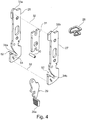
- the drawer front connecting device 9 designed as a multi-part structural unit comprises as elements an outer housing 20, an inner housing 21, a front connector 22, adjusting elements 23, 24 and a hanging component 25.
- the elements 20, 21, 22, 23 and 24 are combined in a recessed receiving area at the front end 18a of the drawer side part 18 so that they can be accommodated in a fixed but detachable manner.
- the hanging component 25 is designed to be screwed, for example, fixed to an inside 15a of the drawer front 15.
- the drawer front 15 is connected to the drawer side parts 17 and 18 via the respective interaction of a hanging component 25 with an associated one Front connector 22.
- the component comprising the combined elements 20, 21, 22, 23 and 24 is accommodated on the front of each drawer side part 17, 18.
- these components cooperate with an associated suspension component 25.
- exactly two hanging components 25 are fixed on the inside 15a of the drawer front 15 at a point which is coordinated with them.
- connection is then made by hanging the drawer front 15 over the two hanging components 25 on the respective front connectors 22 on the two drawer side parts 17 and 18.
- the elements 20, 21, 23, 24 and 31 and a sliding element 31 on the front connector 22 serve for height adjustment and for side adjustment of the drawer front 15 on the rest of the drawer or on the drawer side parts 17 and 18.
- the front connector 22 has two narrow, preferably essentially plate-shaped connector plates 26 and 27, a spring 28, a latching member 29 and a bearing element 30 for the detachable mounting of the latching member 29 on the connector plates 26, 27.
- the spring 28 is on the two connector plates 26 , 27 and has the effect that the locking member 29 can be deflected or pivoted somewhat about the longitudinal axis of the bearing element 30 and is biased in a pivoting direction R1.
- the latching member 29 can be avoided in the pivoting direction R2 opposite to the pivoting direction R1.
- the evasibility is used to cancel a latching, which can be set up automatically by the latching member 29, with which the hanging component 25 can be latched on the front connector 22. Unlocking is carried out by manually pressing from the outside against an operating section 29a on the locking member 29 against the force or spring action of the spring 28.
- the displacement element 31 associated with the lateral adjustment is accommodated.
- the adjusting element 24 which is rotatable from the outside about its longitudinal axis, is provided.
- the actuating element 24 engages transversely through openings in the outer housing 20, the inner housing 21, the two connector plates 26, 27 and the displacement element 31.
- the two connector plates 26, 27 are aligned parallel to one another and in a width direction B of the front connector 22 over the distance a (s. Fig. 5 ) spaced apart from one another over the predominant extent and firmly connected to one another by elements not shown in concrete terms, such as, for example, two transverse bolts.
- the longitudinal axes 32 of the elements or of the transverse bolts are shown in Fig. 4 indicated by dashed lines, each element being firmly connected with its two ends to the associated connector plate 26 and 27, respectively.
- the two elements are preferably aligned parallel to the width direction B or in particular parallel to the bearing element 30.
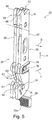
- An upper ramp 33 and a lower ramp 34 are provided on the front connector 22 in a vertical direction H of the front connector 22.
- the flat ramps 33, 34 are oriented obliquely in a depth direction T of the front connector 22 and or in the direction away from a front side 35 of the front connector 22 sloping backwards or in the direction of a rear side 36 of the front connector 22.
- a plane E1 of the upper ramp 33 is parallel to a plane E2 of the lower ramp 34 (see. Fig. 6 ).
- the upper ramp 33 has an upper narrow side 33a of the first connector plate 26 and an upper narrow side 33b of the Connector plate 27 on.
- the narrow sides 33a and 33b lie in a common spanned spatial plane.
- the lower ramp 34 has a lower narrow side 34a of the first connector plate 26 and a lower narrow side 34b of the connector plate 27.
- the narrow sides 34a and 34b lie in a common imaginary spanned spatial plane, which is parallel to the spatial plane of the upper narrow sides 33a, 33b.
- the two upper narrow sides 33a and 33b are spaced apart from one another in the width direction B, as are the two lower narrow sides 34a and 34b.
- the two upper narrow sides 33a, 33b form a two-lane support 39 for an upper support section 37 of the hanging component 25 and the two lower narrow sides 34a and 34b form a two-lane support 40 for a lower supporting section 38 of the hanging component 25.
- the support sections 37 and 38 are preferably of the same type or identical.
- the support sections 37, 38 are preferably formed as pin-like or elongated components, here, for example, each as a pin or bolt with a concave or cylindrical outer shape. Other shapes such as B. a polygonal outer shape of the support portions 37, 38 are possible.
- the upper support section 37 slides along the two upper narrow sides 33a, 33b of the support 39 when the drawer front is connected to the drawer side parts 17, 18. Accordingly or simultaneously, the lower support section 38 slides along the two lower narrow sides 34a, 34b the support 40 when connecting the drawer front 15 to the drawer side parts 17, 18 obliquely downwards or somewhat in the depth direction T and downwards against the height direction H. The sliding movement is supported by the weight of the drawer front 15.
- Fasteners such as B. connecting screws with which the hanging component 25 is attached to the inside 15a of the drawer front 15 by anchoring in the material of the drawer front 15, not shown.
- openings 47, 48 and 49 are formed on the mounting component 25 on a component rear side 42 of a base body 41 of the mounting component 25 for gripping through the connecting elements (see FIG. Fig. 3 ).
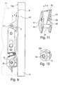
- the base body 41 of the hanging component 25, which is preferably formed from a bent or edged sheet metal material, also comprises on opposite outer edges of the Component rear side 42 protrudes upper side flanks 43, 44 and lower side flanks 45, 46. Between the upper side flanks 43, 44 the upper support section 37 is received and between the lower side flanks 45, 46 the lower support section 38 is received. Both support sections 37 and 38 or their respective central longitudinal axes are at the same distance b from the rear side 42 of the component (see FIG. Fig. 9 ). In the height direction H, the two support sections 37, 38 are exactly one above the other or in alignment with one another.
- the drawer front 15 For the assembly of the drawer front 15, it is preferred in practice if the remaining part of the drawer 2 consisting of the assembled components 16-19 is accommodated on the furniture body 12 via the rail guides 13, 14 and moved out relative to the furniture body 12, according to Fig. 1 . Then the drawer front 15 can advantageously be attached to the drawer side parts 17, 18, which can be done in different ways.
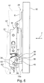
- Fig. 6 the drawer side part 17, on which the front connector 22 is fixedly attached, is only indicated with a plane E, within which a front end front edge of the drawer side part 17 lies.
- the slightly recessed position of the front connector 22 within the hollow front section of the drawer side part 17 can be seen.
- the lower support section 38 in the region of the lower ramp 34 is attached to a suspension contour 50 with a contour section 51 (see FIG. Fig. 5 ) in the vicinity of the lower ramp 34 on the front connector 22.
- the upper support section 37 is still removed from the upper ramp 33 (see. Fig. 6 ).
- the lower ramp 34 is formed in each case by a slot-shaped cutout 52 in the connector plates 26 and 27.
- the lower ramp 34 is thus open to the front 35 of the front connector 22, so that the lower support section 38 can be threaded into the cutouts 52.
- the support section 38 is forcibly guided along the lower ramp 34 or both support surfaces 34a and 34b in such a way that the support section 38 rests on both support surfaces 34a, 34b on the underside. This favors a correct spatial alignment of the drawer front 15 on the drawer side parts 17, 18.
- the support section 38 is in particular aligned such that the longitudinal axis of the support section 38 runs horizontally.
- the lower support section 38 When the drawer front 15 is moved further in the direction of an end 53 of the lower ramp 34, the lower support section 38 may come into supportive contact with a recess 54 of the hanging contour 50 in front of the lower ramp 34.
- the depression 54 is formed, for example, by a trough-like dent on the narrow sides of the two connector plates 26, 27.
- the lower support section 38 abuts the narrow sides of the cutout 52 opposite the lower ramp 34, the narrow sides being formed on the two connector plates 26, 27.
- the drawer front 15 is given a downward movement.
- the lower support section reaches the lower ramp 34 and is supported on this.
- the upper support section 37 reaches the upper ramp 33 and is also supported on this.
- the drawer front 15 can automatically slide obliquely downwards in the sliding direction R, supported by the weight of the drawer front 15 and / or by the fitter.
- the upper support section 37 slides on the upper ramp 33 or on the two upper narrow sides 33a, 33b, which provide a two-lane upper support surface or two-lane guideway for the upper support section 37.
- the lower support section 38 slides on the lower ramp 34 or on the two lower narrow sides 34a, 34b, which provide a two-lane lower support surface or two-lane guideway for the lower support section 38.
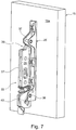
- the connecting movement of the hanging components 25 relative to the front connectors 22 and thus the drawer front 15 in the direction of the end faces of the two drawer side parts 17, 18 is not limited by a stop acting, for example, on the upper support section 37 and / or, for example, the lower support section 38, which in particular Fig. 9 illustrates that in the sliding direction R of the upper support section 37 and of the lower support section 38 behind the support sections 37 and 38 the associated ramps 33 and 34 respectively extend a little further or the respective upper narrow sides 33a, 33b and the respective lower narrow sides 34a, 34b. Rather, the aforementioned sliding or connecting movement is mechanically limited by the fact that the inside 15a of the drawer front bears against the respective narrow strip-shaped end face according to plane E of the drawer side parts 17 and 18.
- the narrow front end of the drawer side part 17 and the narrow front end of the drawer side part 18 lie in adjacent parallel room levels.
- the plane E borders parallel to the inside 15a of the drawer front 15.
- control element 24 on the front connector 22 is omitted.
- a locking device for securing the drawer front 15 on the drawer side parts 17, 18 is set up with the locking member 29.
- a projection 29b of the latching member 29 comes into abutment against the lower support section 38 with the force of the spring 28, so that the lower support section 38 cannot be moved or secured unintentionally upwards along the ramp 34, that is to say in the direction toward the oblique one downward sliding direction R when the connection state is reached.
- an elevation section 55 with two mutually opposite elevation sections 56 and 57 (see FIG. Fig. 11 ).
- the two elevation sections 56 and 57 are separated from one another in the width direction of the suspension component 25 by a free space or a material-free distance c.
- the distance c is matched to a dimension of the contour section 51 of the front connector 22 in the width direction B.
- This width dimension is slightly less than the width of the front connector 22, which is predetermined by the flat outer sides of the two connector plates 26 and 27.
- the contour section 51 has two tooth-shaped sections on the respective connector plates 26 and 27 which are bent slightly towards one another.
- the two elevation sections 56 and 57 are preferably identical and of the same length.
- the elevation sections 56 are provided on the inside on the side flank 45 and the elevation sections 57 are provided on the inside on the side flank 46.
- the elevation sections 56, 57 are configured as stub axles with a cylindrical outer shape and a flat, if necessary slightly convex, end face.
- the elevation sections 56 and 57 are particularly advantageous for an alternative procedure for attaching the drawer front 15 to the drawer side parts 17, 18, which differs from that according to FIG Figures 6-9 described procedure differs.
- the drawer front 15 is not aligned vertically, but is inclined at an angle to the vertical, with the lower region of the drawer front 15 leading to the drawer side parts 17, 18, so that the hanging component 25 on the front connector 22 with the lower support section 38 and the raised sections 56 and 57 can be supported in a stationary pre-assembly position or self-retaining or freely hanging on the drawer side parts 17, 18 or on their front connectors 22.
- the two elevation subsections 56 and 57 come into abutment against the hanging contour 50 or on the contour section 51.
- the upper region of the drawer front 15 is removed or spaced apart from the drawer side parts 17, 18 due to its inclined position in the pre-assembly position.
- the drawer front 15 is subsequently pivoted into the vertical orientation by the fitter, with the lower one Support section 38 by contact with the contour section 50 provides a pivot axis, the upper region of the drawer front 15 approaches the upper ramp 33, so that the upper support section 37 then reaches the upper ramp 33 and can slide down there, at the same time as the lower support section 38 slides down along the lower ramp 34 .
- an upward slope 58 is arranged in front of the upper ramp 33.
- the ramp slope 58 is two-lane and includes a first ramp track 59 and a second ramp track 60.
- the first ramp track 59 is formed by a section of the narrow side of the first connector plate 26 and the second ramp track 60 is formed by a section of the narrow side of the second connector plate 27.
- the slope of the run-up track is 59 identical to the inclination of the run-up track 60 and against the inclination of the upper ramp 33.
- the upper support section 37 When pivoting the drawer front 15 against the drawer side parts 17, 18, the upper support section 37 first reaches the ramp slope 58 and is then guided obliquely upwards along the ramp slope 58 when the drawer front 15 is pivoted further. At the same time, the drawer front 15 remains supported on the contour section 50 at the bottom, which is done via the lower support section 38 and the two elevation sections 56 and 57.
Landscapes
- Drawers Of Furniture (AREA)
Applications Claiming Priority (1)
| Application Number | Priority Date | Filing Date | Title |
|---|---|---|---|
| DE202018107032.0U DE202018107032U1 (de) | 2018-12-10 | 2018-12-10 | Schubladenfront-Verbindungsvorrichtung und Schublade |
Publications (2)
| Publication Number | Publication Date |
|---|---|
| EP3666121A1 true EP3666121A1 (fr) | 2020-06-17 |
| EP3666121B1 EP3666121B1 (fr) | 2021-08-11 |
Family
ID=68424745
Family Applications (1)
| Application Number | Title | Priority Date | Filing Date |
|---|---|---|---|
| EP19206413.7A Active EP3666121B1 (fr) | 2018-12-10 | 2019-10-31 | Dispositif de raccordement de l'avant de tiroir et tiroir |
Country Status (2)
| Country | Link |
|---|---|
| EP (1) | EP3666121B1 (fr) |
| DE (1) | DE202018107032U1 (fr) |
Families Citing this family (1)
| Publication number | Priority date | Publication date | Assignee | Title |
|---|---|---|---|---|
| DE102023130093A1 (de) | 2023-10-31 | 2025-04-30 | Paul Hettich Gmbh & Co. Kg | Blendenträger |
Citations (4)
| Publication number | Priority date | Publication date | Assignee | Title |
|---|---|---|---|---|
| US5364181A (en) * | 1992-10-12 | 1994-11-15 | Grass Ag | Front adjustment for a panel with snap-on mechanism for a drawer |
| WO2012068599A1 (fr) * | 2010-11-23 | 2012-05-31 | Julius Blum Gmbh | Ferrure de meuble pour la fixation d'un panneau avant |
| WO2012171047A1 (fr) * | 2011-05-24 | 2012-12-20 | Julius Blum Gmbh | Dispositif de fixation servant à fixer un panneau de façade sur un tiroir |
| EP3335591A1 (fr) * | 2016-12-16 | 2018-06-20 | Paul Hettich GmbH & Co. KG | Dispositif d'arrêt à plusieurs reprises pour une ferrure d'arrêt pour un châssis, châssis et tiroir |
Family Cites Families (1)
| Publication number | Priority date | Publication date | Assignee | Title |
|---|---|---|---|---|
| DE202012003125U1 (de) * | 2012-02-20 | 2013-06-13 | Bulthaup Gmbh & Co. Kg | Auszug |
-
2018
- 2018-12-10 DE DE202018107032.0U patent/DE202018107032U1/de not_active Expired - Lifetime
-
2019
- 2019-10-31 EP EP19206413.7A patent/EP3666121B1/fr active Active
Patent Citations (4)
| Publication number | Priority date | Publication date | Assignee | Title |
|---|---|---|---|---|
| US5364181A (en) * | 1992-10-12 | 1994-11-15 | Grass Ag | Front adjustment for a panel with snap-on mechanism for a drawer |
| WO2012068599A1 (fr) * | 2010-11-23 | 2012-05-31 | Julius Blum Gmbh | Ferrure de meuble pour la fixation d'un panneau avant |
| WO2012171047A1 (fr) * | 2011-05-24 | 2012-12-20 | Julius Blum Gmbh | Dispositif de fixation servant à fixer un panneau de façade sur un tiroir |
| EP3335591A1 (fr) * | 2016-12-16 | 2018-06-20 | Paul Hettich GmbH & Co. KG | Dispositif d'arrêt à plusieurs reprises pour une ferrure d'arrêt pour un châssis, châssis et tiroir |
Also Published As
| Publication number | Publication date |
|---|---|
| DE202018107032U1 (de) | 2020-03-13 |
| EP3666121B1 (fr) | 2021-08-11 |
Similar Documents
| Publication | Publication Date | Title |
|---|---|---|
| DE69705662T2 (de) | Rollvorrichtung für Schiebetüren, Fenster oder ähnliches | |
| AT510781B1 (de) | Möbelbeschlag zur frontblendenbefestigung | |
| EP4010554B1 (fr) | Ferrure de porte coulissante, meuble et procédé d'assemblage d'une ferrure de porte coulissante | |
| EP3561207B1 (fr) | Moyen de raccordement et partie de meuble | |
| WO2018033465A1 (fr) | Châssis destiné à un tiroir | |
| EP2606766A1 (fr) | Guidage d'extraction pour tiroirs coulissants avec crochet de préhension | |
| EP0940067A2 (fr) | Armoire de distribution comportant une plaque de montage | |
| EP1614369B1 (fr) | Cadre de tiroir | |
| EP2628411A2 (fr) | Tiroir | |
| EP3585210B1 (fr) | Tiroir et procédé de montage d'un tiroir | |
| EP3100641B1 (fr) | Panneau arrière de tiroir, tiroir et meuble a tiroir | |
| DE202011104559U1 (de) | Vorrichtung mit einer Anbringeinrichtung zur lösbaren Verbindung eines Frontteils einer Schublade mit einer Profilleiste sowie Möbel | |
| EP3082507B1 (fr) | Tiroir de meuble et élément de paroi de tiroir pour un tiroir | |
| EP3666121B1 (fr) | Dispositif de raccordement de l'avant de tiroir et tiroir | |
| EP4558009B1 (fr) | Panneau lateral de tiroir | |
| EP3735150B1 (fr) | Ensemble formé d'une nervure d'appui pour fond de tiroir et d'un dispositif de retenue | |
| WO2024016032A1 (fr) | Paroi latérale de tiroir | |
| DE602005003380T2 (de) | Verfahren zur Montage eines Verstärkungsteils auf die Frontplatte eines Kühl- oder Gefrierschrankes | |
| DE102006059750B4 (de) | Möbelverkettungselement und damit ausgestattetes Möbel | |
| DE4139441C2 (de) | Schublade | |
| DE202018107031U1 (de) | Schubladenfront-Verbindungsvorrichtung und Schublade | |
| DE202008015077U1 (de) | Adapter zur Befestigung von Solarmodulen, mit Adapter befestigte Solarmodule und Werkzeug zum Lösen der Befestigung | |
| DE19734647B4 (de) | Beschlagteil an einem Flügel oder einem festen Rahmen eines Fensters, einer Tür od. dgl. | |
| EP3666124A1 (fr) | Dispositif de réglage de châssis latéral destiné au réglage latéral d'un avant de tiroir par rapport à un châssis latéral | |
| WO2010054998A2 (fr) | Adaptateur conçu pour la fixation de modules solaires, modules solaires fixés à l'aide d'adaptateurs et procédé de fixation de modules solaires |
Legal Events
| Date | Code | Title | Description |
|---|---|---|---|
| PUAI | Public reference made under article 153(3) epc to a published international application that has entered the european phase |
Free format text: ORIGINAL CODE: 0009012 |
|
| STAA | Information on the status of an ep patent application or granted ep patent |
Free format text: STATUS: THE APPLICATION HAS BEEN PUBLISHED |
|
| AK | Designated contracting states |
Kind code of ref document: A1 Designated state(s): AL AT BE BG CH CY CZ DE DK EE ES FI FR GB GR HR HU IE IS IT LI LT LU LV MC MK MT NL NO PL PT RO RS SE SI SK SM TR |
|
| AX | Request for extension of the european patent |
Extension state: BA ME |
|
| STAA | Information on the status of an ep patent application or granted ep patent |
Free format text: STATUS: REQUEST FOR EXAMINATION WAS MADE |
|
| 17P | Request for examination filed |
Effective date: 20201029 |
|
| RBV | Designated contracting states (corrected) |
Designated state(s): AL AT BE BG CH CY CZ DE DK EE ES FI FR GB GR HR HU IE IS IT LI LT LU LV MC MK MT NL NO PL PT RO RS SE SI SK SM TR |
|
| GRAP | Despatch of communication of intention to grant a patent |
Free format text: ORIGINAL CODE: EPIDOSNIGR1 |
|
| STAA | Information on the status of an ep patent application or granted ep patent |
Free format text: STATUS: GRANT OF PATENT IS INTENDED |
|
| INTG | Intention to grant announced |
Effective date: 20210330 |
|
| GRAS | Grant fee paid |
Free format text: ORIGINAL CODE: EPIDOSNIGR3 |
|
| GRAA | (expected) grant |
Free format text: ORIGINAL CODE: 0009210 |
|
| STAA | Information on the status of an ep patent application or granted ep patent |
Free format text: STATUS: THE PATENT HAS BEEN GRANTED |
|
| AK | Designated contracting states |
Kind code of ref document: B1 Designated state(s): AL AT BE BG CH CY CZ DE DK EE ES FI FR GB GR HR HU IE IS IT LI LT LU LV MC MK MT NL NO PL PT RO RS SE SI SK SM TR |
|
| REG | Reference to a national code |
Ref country code: CH Ref legal event code: EP |
|
| REG | Reference to a national code |
Ref country code: DE Ref legal event code: R096 Ref document number: 502019002030 Country of ref document: DE |
|
| REG | Reference to a national code |
Ref country code: IE Ref legal event code: FG4D Free format text: LANGUAGE OF EP DOCUMENT: GERMAN Ref country code: AT Ref legal event code: REF Ref document number: 1418480 Country of ref document: AT Kind code of ref document: T Effective date: 20210915 |
|
| REG | Reference to a national code |
Ref country code: LT Ref legal event code: MG9D |
|
| REG | Reference to a national code |
Ref country code: NL Ref legal event code: MP Effective date: 20210811 |
|
| PG25 | Lapsed in a contracting state [announced via postgrant information from national office to epo] |
Ref country code: LT Free format text: LAPSE BECAUSE OF FAILURE TO SUBMIT A TRANSLATION OF THE DESCRIPTION OR TO PAY THE FEE WITHIN THE PRESCRIBED TIME-LIMIT Effective date: 20210811 Ref country code: BG Free format text: LAPSE BECAUSE OF FAILURE TO SUBMIT A TRANSLATION OF THE DESCRIPTION OR TO PAY THE FEE WITHIN THE PRESCRIBED TIME-LIMIT Effective date: 20211111 Ref country code: FI Free format text: LAPSE BECAUSE OF FAILURE TO SUBMIT A TRANSLATION OF THE DESCRIPTION OR TO PAY THE FEE WITHIN THE PRESCRIBED TIME-LIMIT Effective date: 20210811 Ref country code: HR Free format text: LAPSE BECAUSE OF FAILURE TO SUBMIT A TRANSLATION OF THE DESCRIPTION OR TO PAY THE FEE WITHIN THE PRESCRIBED TIME-LIMIT Effective date: 20210811 Ref country code: NO Free format text: LAPSE BECAUSE OF FAILURE TO SUBMIT A TRANSLATION OF THE DESCRIPTION OR TO PAY THE FEE WITHIN THE PRESCRIBED TIME-LIMIT Effective date: 20211111 Ref country code: PT Free format text: LAPSE BECAUSE OF FAILURE TO SUBMIT A TRANSLATION OF THE DESCRIPTION OR TO PAY THE FEE WITHIN THE PRESCRIBED TIME-LIMIT Effective date: 20211213 Ref country code: SE Free format text: LAPSE BECAUSE OF FAILURE TO SUBMIT A TRANSLATION OF THE DESCRIPTION OR TO PAY THE FEE WITHIN THE PRESCRIBED TIME-LIMIT Effective date: 20210811 Ref country code: RS Free format text: LAPSE BECAUSE OF FAILURE TO SUBMIT A TRANSLATION OF THE DESCRIPTION OR TO PAY THE FEE WITHIN THE PRESCRIBED TIME-LIMIT Effective date: 20210811 Ref country code: ES Free format text: LAPSE BECAUSE OF FAILURE TO SUBMIT A TRANSLATION OF THE DESCRIPTION OR TO PAY THE FEE WITHIN THE PRESCRIBED TIME-LIMIT Effective date: 20210811 |
|
| PG25 | Lapsed in a contracting state [announced via postgrant information from national office to epo] |
Ref country code: PL Free format text: LAPSE BECAUSE OF FAILURE TO SUBMIT A TRANSLATION OF THE DESCRIPTION OR TO PAY THE FEE WITHIN THE PRESCRIBED TIME-LIMIT Effective date: 20210811 Ref country code: LV Free format text: LAPSE BECAUSE OF FAILURE TO SUBMIT A TRANSLATION OF THE DESCRIPTION OR TO PAY THE FEE WITHIN THE PRESCRIBED TIME-LIMIT Effective date: 20210811 Ref country code: GR Free format text: LAPSE BECAUSE OF FAILURE TO SUBMIT A TRANSLATION OF THE DESCRIPTION OR TO PAY THE FEE WITHIN THE PRESCRIBED TIME-LIMIT Effective date: 20211112 |
|
| PG25 | Lapsed in a contracting state [announced via postgrant information from national office to epo] |
Ref country code: NL Free format text: LAPSE BECAUSE OF FAILURE TO SUBMIT A TRANSLATION OF THE DESCRIPTION OR TO PAY THE FEE WITHIN THE PRESCRIBED TIME-LIMIT Effective date: 20210811 |
|
| PG25 | Lapsed in a contracting state [announced via postgrant information from national office to epo] |
Ref country code: DK Free format text: LAPSE BECAUSE OF FAILURE TO SUBMIT A TRANSLATION OF THE DESCRIPTION OR TO PAY THE FEE WITHIN THE PRESCRIBED TIME-LIMIT Effective date: 20210811 |
|
| REG | Reference to a national code |
Ref country code: DE Ref legal event code: R097 Ref document number: 502019002030 Country of ref document: DE |
|
| PG25 | Lapsed in a contracting state [announced via postgrant information from national office to epo] |
Ref country code: SM Free format text: LAPSE BECAUSE OF FAILURE TO SUBMIT A TRANSLATION OF THE DESCRIPTION OR TO PAY THE FEE WITHIN THE PRESCRIBED TIME-LIMIT Effective date: 20210811 Ref country code: SK Free format text: LAPSE BECAUSE OF FAILURE TO SUBMIT A TRANSLATION OF THE DESCRIPTION OR TO PAY THE FEE WITHIN THE PRESCRIBED TIME-LIMIT Effective date: 20210811 Ref country code: RO Free format text: LAPSE BECAUSE OF FAILURE TO SUBMIT A TRANSLATION OF THE DESCRIPTION OR TO PAY THE FEE WITHIN THE PRESCRIBED TIME-LIMIT Effective date: 20210811 Ref country code: EE Free format text: LAPSE BECAUSE OF FAILURE TO SUBMIT A TRANSLATION OF THE DESCRIPTION OR TO PAY THE FEE WITHIN THE PRESCRIBED TIME-LIMIT Effective date: 20210811 Ref country code: CZ Free format text: LAPSE BECAUSE OF FAILURE TO SUBMIT A TRANSLATION OF THE DESCRIPTION OR TO PAY THE FEE WITHIN THE PRESCRIBED TIME-LIMIT Effective date: 20210811 Ref country code: AL Free format text: LAPSE BECAUSE OF FAILURE TO SUBMIT A TRANSLATION OF THE DESCRIPTION OR TO PAY THE FEE WITHIN THE PRESCRIBED TIME-LIMIT Effective date: 20210811 |
|
| PLBE | No opposition filed within time limit |
Free format text: ORIGINAL CODE: 0009261 |
|
| STAA | Information on the status of an ep patent application or granted ep patent |
Free format text: STATUS: NO OPPOSITION FILED WITHIN TIME LIMIT |
|
| REG | Reference to a national code |
Ref country code: BE Ref legal event code: MM Effective date: 20211031 |
|
| PG25 | Lapsed in a contracting state [announced via postgrant information from national office to epo] |
Ref country code: MC Free format text: LAPSE BECAUSE OF FAILURE TO SUBMIT A TRANSLATION OF THE DESCRIPTION OR TO PAY THE FEE WITHIN THE PRESCRIBED TIME-LIMIT Effective date: 20210811 |
|
| 26N | No opposition filed |
Effective date: 20220512 |
|
| PG25 | Lapsed in a contracting state [announced via postgrant information from national office to epo] |
Ref country code: LU Free format text: LAPSE BECAUSE OF NON-PAYMENT OF DUE FEES Effective date: 20211031 Ref country code: BE Free format text: LAPSE BECAUSE OF NON-PAYMENT OF DUE FEES Effective date: 20211031 |
|
| PG25 | Lapsed in a contracting state [announced via postgrant information from national office to epo] |
Ref country code: SI Free format text: LAPSE BECAUSE OF FAILURE TO SUBMIT A TRANSLATION OF THE DESCRIPTION OR TO PAY THE FEE WITHIN THE PRESCRIBED TIME-LIMIT Effective date: 20210811 |
|
| PG25 | Lapsed in a contracting state [announced via postgrant information from national office to epo] |
Ref country code: FR Free format text: LAPSE BECAUSE OF NON-PAYMENT OF DUE FEES Effective date: 20211031 |
|
| PG25 | Lapsed in a contracting state [announced via postgrant information from national office to epo] |
Ref country code: IE Free format text: LAPSE BECAUSE OF NON-PAYMENT OF DUE FEES Effective date: 20211031 |
|
| REG | Reference to a national code |
Ref country code: CH Ref legal event code: PL |
|
| PG25 | Lapsed in a contracting state [announced via postgrant information from national office to epo] |
Ref country code: CY Free format text: LAPSE BECAUSE OF FAILURE TO SUBMIT A TRANSLATION OF THE DESCRIPTION OR TO PAY THE FEE WITHIN THE PRESCRIBED TIME-LIMIT Effective date: 20210811 |
|
| PG25 | Lapsed in a contracting state [announced via postgrant information from national office to epo] |
Ref country code: LI Free format text: LAPSE BECAUSE OF NON-PAYMENT OF DUE FEES Effective date: 20221031 Ref country code: HU Free format text: LAPSE BECAUSE OF FAILURE TO SUBMIT A TRANSLATION OF THE DESCRIPTION OR TO PAY THE FEE WITHIN THE PRESCRIBED TIME-LIMIT; INVALID AB INITIO Effective date: 20191031 Ref country code: CH Free format text: LAPSE BECAUSE OF NON-PAYMENT OF DUE FEES Effective date: 20221031 |
|
| PG25 | Lapsed in a contracting state [announced via postgrant information from national office to epo] |
Ref country code: MK Free format text: LAPSE BECAUSE OF FAILURE TO SUBMIT A TRANSLATION OF THE DESCRIPTION OR TO PAY THE FEE WITHIN THE PRESCRIBED TIME-LIMIT Effective date: 20210811 |
|
| GBPC | Gb: european patent ceased through non-payment of renewal fee |
Effective date: 20231031 |
|
| PG25 | Lapsed in a contracting state [announced via postgrant information from national office to epo] |
Ref country code: GB Free format text: LAPSE BECAUSE OF NON-PAYMENT OF DUE FEES Effective date: 20231031 |
|
| PG25 | Lapsed in a contracting state [announced via postgrant information from national office to epo] |
Ref country code: GB Free format text: LAPSE BECAUSE OF NON-PAYMENT OF DUE FEES Effective date: 20231031 |
|
| PG25 | Lapsed in a contracting state [announced via postgrant information from national office to epo] |
Ref country code: MT Free format text: LAPSE BECAUSE OF FAILURE TO SUBMIT A TRANSLATION OF THE DESCRIPTION OR TO PAY THE FEE WITHIN THE PRESCRIBED TIME-LIMIT Effective date: 20210811 |
|
| REG | Reference to a national code |
Ref country code: DE Ref legal event code: R082 Ref document number: 502019002030 Country of ref document: DE Representative=s name: RAVENSPAT PATENTANWAELTE PARTNERSCHAFT MBB, DE |
|
| PG25 | Lapsed in a contracting state [announced via postgrant information from national office to epo] |
Ref country code: TR Free format text: LAPSE BECAUSE OF FAILURE TO SUBMIT A TRANSLATION OF THE DESCRIPTION OR TO PAY THE FEE WITHIN THE PRESCRIBED TIME-LIMIT Effective date: 20210811 |
|
| PGFP | Annual fee paid to national office [announced via postgrant information from national office to epo] |
Ref country code: DE Payment date: 20251024 Year of fee payment: 7 |
|
| PGFP | Annual fee paid to national office [announced via postgrant information from national office to epo] |
Ref country code: AT Payment date: 20251027 Year of fee payment: 7 |
|
| PGFP | Annual fee paid to national office [announced via postgrant information from national office to epo] |
Ref country code: IT Payment date: 20251015 Year of fee payment: 7 |