EP3666123A1 - Schubladenfront-verstellvorrichtung und schublade - Google Patents
Schubladenfront-verstellvorrichtung und schublade Download PDFInfo
- Publication number
- EP3666123A1 EP3666123A1 EP19202341.4A EP19202341A EP3666123A1 EP 3666123 A1 EP3666123 A1 EP 3666123A1 EP 19202341 A EP19202341 A EP 19202341A EP 3666123 A1 EP3666123 A1 EP 3666123A1
- Authority
- EP
- European Patent Office
- Prior art keywords
- drawer
- friction
- drawer front
- housing
- adjusting
- Prior art date
- Legal status (The legal status is an assumption and is not a legal conclusion. Google has not performed a legal analysis and makes no representation as to the accuracy of the status listed.)
- Granted
Links
Images





Classifications
-
- A—HUMAN NECESSITIES
- A47—FURNITURE; DOMESTIC ARTICLES OR APPLIANCES; COFFEE MILLS; SPICE MILLS; SUCTION CLEANERS IN GENERAL
- A47B—TABLES; DESKS; OFFICE FURNITURE; CABINETS; DRAWERS; GENERAL DETAILS OF FURNITURE
- A47B88/00—Drawers for tables, cabinets or like furniture; Guides for drawers
- A47B88/90—Constructional details of drawers
- A47B88/944—Drawers characterised by the front panel
- A47B88/95—Drawers characterised by the front panel characterised by connection means for the front panel
- A47B88/956—Drawers characterised by the front panel characterised by connection means for the front panel for enabling adjustment of the front panel
-
- A—HUMAN NECESSITIES
- A47—FURNITURE; DOMESTIC ARTICLES OR APPLIANCES; COFFEE MILLS; SPICE MILLS; SUCTION CLEANERS IN GENERAL
- A47B—TABLES; DESKS; OFFICE FURNITURE; CABINETS; DRAWERS; GENERAL DETAILS OF FURNITURE
- A47B88/00—Drawers for tables, cabinets or like furniture; Guides for drawers
- A47B88/90—Constructional details of drawers
- A47B88/944—Drawers characterised by the front panel
- A47B88/95—Drawers characterised by the front panel characterised by connection means for the front panel
- A47B2088/954—Drawers characterised by the front panel characterised by connection means for the front panel fastening the front panel by a sprung bolt, latch or lock-bolt
Definitions
- a drawer front component being attached to the drawer side parts via a drawer front connecting device.
- the drawer front is preferably detachably or interchangeably attachable to the two drawer side parts.
- Previous drawer front connecting devices are also only of limited suitability with regard to an exact height and / or side adjustment of the drawer front.
- the object of the present invention is to provide an improved drawer front connecting device of the type described in the introduction, in particular with regard to simple and exact height and / or lateral adjustment of the drawer front.
- the invention is based on a drawer front adjustment device for adjusting a drawer front relative to a drawer side part in an adjustment direction, in particular for lateral adjustment of the drawer front.
- the drawer front adjusting device comprises a housing, a front connector and an actuating element which can be rotated by an operation from outside, the front connector being displaceable relative to the housing and being able to be arranged by attaching the housing to the drawer side part, and wherein Front connector can be coupled to the drawer front, the front connector being displaceable relative to the housing by operating the actuating element in order to bring the front connector into an offset position on the housing from a plurality of possible offset positions of the front connector on the housing, so that in the arranged state the drawer side part, the displacement of the front connector coupled to the drawer front causes the adjustment of the drawer front, a friction structure with friction surfaces on the actuating element and / or on a counter-section on the housing being formed such that as the rotational movement of the actuating element progresses elements at least two friction surfaces can be brought into contact with one another and can be separated again, so that friction effects due to abutting friction surfaces change, in particular occur and disappear again, so that due to the changing friction effects
- the drawer front adjustment device is preferably designed as a height adjustment device for the drawer front or as a side adjustment device for the drawer front.
- the drawer front is adjusted relative to the remaining drawer in the height direction or side direction.
- the drawer front is adjusted in a height direction or in the use state in the vertical direction or in the use state transversely to the vertical and in the lateral or width direction of the drawer front.
- This can be used to set up a front image of the piece of furniture, in particular, so that the front side edges of the drawer front can be adjusted to neighboring drawer fronts or other furniture edges.
- uniform gap widths can be set up on the furniture between the edges of the neighboring drawer fronts and the flush edges of the neighboring drawer fronts above and below and to the right and left.
- the adjustment path between two changing friction effects is preferably a fraction of a millimeter, for example 0.2 to 0.8 millimeters, in particular for example 0.5 millimeters. This allows the drawer front to be adjusted in height or in the side or in the width direction in steps of 0.5 millimeters, for example.
- the frictional resistance when turning the actuating element or against the rotational movement imposed from the outside is preferably alternately strong and weakly noticeable for the fitter when Turn the actuator.
- the frictional resistance is alternately clearly noticeable and disappearing or not noticeable or alternately increasing and decreasing noticeable.
- the adjustment direction corresponds to the direction of the axis of rotation about which the adjusting element can be rotated.
- the adjusting element has a vertically aligned longitudinal axis and in a side adjustment the adjusting element has a horizontally aligned longitudinal axis.
- the longitudinal axis of the actuating element is preferably oriented in the direction of a width of the drawer front or in the lateral direction.
- the control element By operating from the outside by z. B. a fitter, the control element is rotated, optionally in one of two possible directions of rotation and depending on it up or down or to the right or left.
- the front connector can accordingly be moved back and forth along an adjustment distance of the front connector provided and limited by stops.
- the front connector is preferably accommodated in a displaceable manner on the housing.
- At least one friction surface is preferably present on the control element on an active section on the control element.
- a plurality of friction surfaces are provided on the control element along the active section, eg. B. if exactly one friction surface is formed on the counter section.
- At least one friction surface on an active section on the counter section is preferably present on the counter section; in particular, a plurality of friction surfaces are present along an active section on the counter section, for. B. if exactly one friction surface is formed on the control element.
- At least some of the friction surfaces on the actuating element interact with at least individual friction surfaces on the counter section or come into frictional contact with one another, depending on the rotational position of the actuating element on the housing. Accordingly, the friction surfaces on the actuating element cannot be brought into frictional engagement with one another, and the friction surfaces on the counter section cannot be brought into frictional engagement with one another.
- the friction surfaces are formed in one piece on the housing. This is particularly advantageous in terms of production technology.
- at least one friction surface of the friction structure on the adjusting element is preferably present, which is matched to the friction surface on the housing.
- friction surfaces are formed in one piece on the actuating element.
- One or more one-piece friction surfaces on the control element can advantageously be formed.
- the friction surfaces are alternately formed with adjacent intermediate areas.
- the entire adjustment path is preferably formed along an adjustment path under consideration with friction surfaces and intermediate areas which are present alternately.
- the friction surfaces are alternately formed along the adjustment path or a path that is covered by the other friction surfaces.
- the adjustment path runs in particular along a path that is circumferential to the rotational or longitudinal axis of the adjusting element.
- the friction structure is formed on a section of the adjusting element that is aligned axially to the longitudinal axis of the adjusting element.
- the adjusting element preferably has a head and an adjoining elongate shaft, the shaft having a smaller external dimension or a smaller diameter than the head.
- At the head is preferably an operating section for attaching a Section of an operating or turning tool designed for torque transmission z.
- the axially aligned section is, for example, an end face on a shaft of the actuating element such as. B. an end face of the actuator.
- the axially aligned section can also be a surface of a head of the actuating element, for example an end-side upper side of the actuating element or a rear or underside of the head section opposite or facing away from the upper side, which projects beyond the smaller-diameter shaft.
- the axially aligned section can also be formed on a shoulder on the head and / or on the shaft or on a thread of the adjusting element.
- the friction structure is formed on a portion of the adjusting element that is aligned circumferentially to the longitudinal axis of the adjusting element.
- This can also be an outside, such as a cylindrical outer surface of a screw element.
- the circumferential section can also be a thread root of a thread on the actuating element.
- the friction structure can be formed or formed on at least one of these surfaces.
- the friction structure or its friction surface is on the cylinder jacket surface, for example, by a convex or differently shaped elevation such as a knob, jag or rib or web, for example with a punctiform or elongated outline.
- a friction surface of the friction structure to be axially secured to the actuating element is trained. This provides a double function with the axial lock and the feedback function for the fitter when turning the control element, which enables a simple and compact design.
- the axial lock is used in particular to secure the axial position of the adjusting element on the housing or a receiving section for rotatably receiving the adjusting element.
- the axial securing device can comprise, for example, a circumferentially interrupted securing element that extends circumferentially to the longitudinal axis of the actuating element, such as, for. B. a clamping washer or a snap ring, which is particularly releasably locked in a circumferential groove on the outside of the actuator.
- the axial securing device can alternatively comprise a securing pin, which is aligned transversely to the longitudinal axis of the adjusting element and extends through it or through a through hole, which protrudes on one or both sides on the outside of the adjusting element or radially to the longitudinal axis of the adjusting element.
- a first friction surface of the friction structure is formed on a first section of the axial securing device which projects radially outside on the circumference of the adjusting element and a second friction surface of the friction structure is formed on a second section of the axial securing device which projects radially outside on the circumference of the adjusting element.
- An embodiment of the invention is characterized in that a plurality of friction surfaces of the friction structure are formed on an outside and / or an inside of the housing. So that the housing is usable for the friction surfaces, which z. B. is technically advantageous. In addition, a number of areas are available on the housing, which can be adapted to the requirements for providing the friction surfaces.
- a friction surface of the friction structure is designed as an elevation structure.
- An elevation structure can be designed variably in shape and size. As a result of the shape of the elevation, the shape can already be used to specify that a secure frictional system takes place on a counter-friction surface with a corresponding rotational position of the actuating element.
- the reliability of the feedback is thus advantageously increased by the friction structure.
- the friction structure comprises a plurality of friction surfaces arranged circumferentially to the longitudinal axis of the adjusting element and separated from one another in the circumferential direction. This is an advantageous embodiment due to the relative movement of the rotatable actuating element and the counter section, which is usually fixed in position.
- the friction structure comprises several regularly arranged friction surfaces. A high level of information can thus be reported back to the fitter, since the regularity provides a reliable conclusion about the adjustment path covered.
- friction surfaces there are several friction surfaces that are regularly spaced apart.
- the friction surfaces are provided in the adjustment direction along the adjustment path of the friction surfaces which can be moved with the adjusting element.
- the plurality of friction surfaces are preferably identical or identical to one another, in each case considered for the actuating element and the counter section.
- the friction surfaces on the counter section include z. B. from the circumferential direction to the rotational or longitudinal axis of the actuating element separate friction surfaces.
- the multiple friction surfaces on the counter section are, for example, circumferential to the longitudinal axis of the actuating element over the entire circumference to the longitudinal axis of the actuating element or preferably over a partial circumference Longitudinal axis of the actuator such. B. distributed over half the circumference.
- the friction structure has a friction surface which is formed on an edge of a through opening in the housing, through which a section of the adjusting element extends. The contacting of the relevant friction surfaces when the actuating element is rotated can thus be predetermined in a space-saving and reliable manner.
- the friction structure comprise a friction surface which is formed on an outer section of the actuating element, the outer section being present adjacent to an edge of a through opening in the housing through which the actuating element engages. This also enables a compact and reliable arrangement of the friction structure.
- a groove base of the groove preferably has a regular polygonal shape with a number of identical planar contour surfaces, from which adjacent contour surfaces are separated from one another by edges.
- the edges each form friction surfaces, which can be brought into contact with a counter-contour, for example an edge of a tab, on a side part of the outer housing and out of contact again when the actuating element is rotated in one direction of rotation.
- a cylindrical groove base with spaced elevations and depressions is also conceivable.
- Friction surfaces due to elevations formed on flat sections are possible and / or on a thread root of a spiral thread on the shaft of the actuating element on the side flanks of the thread.
- a counter contour like a tooth of a sliding element on the front connector engages in the thread and is adjusted depending on the rotation of the control element including the front connector to the outer housing. When rotating, the ridges ratchet over the tooth.
- a z. B. individual web on the outside of the shaft of the actuating element, which interacts with a serrated contour at an edge of an opening in the side part of the outer housing, the shaft of the actuating element reaching through the opening is conceivable as a friction structure. Depending on the rotation of the actuating element, the web comes into frictional contact with a tooth of the tooth contour or comes free therefrom.
- the invention also extends to a drawer with a drawer front and a drawer side part, a drawer front adjusting device being provided according to one of the above-described embodiments.
- the advantages of the drawer when adjusting the drawer front to the rest of the drawer can thus be achieved.
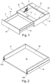
- Fig. 1 1 shows a piece of furniture 1 with a drawer 2 according to the invention protruding from the front of the furniture 1 or moved as far as possible out of the furniture 1.
- the drawer 2 is movable or, in the furniture use state shown, can be moved linearly in the horizontal direction via guide means 4 on a furniture body 3 of the furniture 1.
- the piece of furniture 1 is a box piece of furniture with opposite side walls 5, 6, a bottom 7, a rear wall 8 and two transverse boards 10, 11 provided on the upper side.
- the cross board 10 is horizontally at the top between the two side walls 5, 6 in the front area of the furniture 1 and the cross board 11 is present horizontally at the top between the two side walls 5, 6 in the rear area of the furniture 1, with which the two side walls 5, 6, Bottom 7 and the rear wall 8 are stably connected.
- a cover plate to be provided covering the furniture 1 above the two transverse boards 10, 11 is not shown.
- the guide means 4 comprise a left rail guide 13 and a right rail guide 14, the rail guides 13, 14 acting between the furniture body 3 and the drawer 2 and being designed, for example, as a full extension 12, each with three telescopically displaceable rails.
- the right rail guide 14, which is mirrored to the rail guide 12 on the furniture 1, is shown in FIG Fig. 1 completely covered.
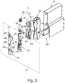
- the drawer 2 is in Fig. 2 shown alone without a drawer front 15. Further elements of the drawer 2 are a drawer base 16, a left drawer side part 17, a right drawer side part 18 and a drawer back 19.
- the two similar drawer side parts 17 and 18 are formed here as drawer frames or as hollow chamber frames made of a folded sheet metal material.
- the drawer side parts 17 and 18 are open at their front ends 17a and 18a and are designed for connection to the drawer front 15 by means of a drawer front connecting device 9 according to the invention.
- a first drawer front connecting device 9 is provided for connecting the drawer front 15 to the drawer side part 17, and for connecting the drawer front 15 to the
- a second drawer front connecting device 9 is provided in the drawer side part 18.
- the connection of the drawer front 15 to the respective drawer side part 17 or 18 is set up identically or is realized with an identical drawer front connecting device 9, that is to say with two drawer front connecting devices 9 on the drawer 2.
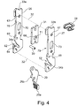
- Fig. 3 The drawer front 15 is not shown, but is only indicated in sections in outline or schematically dashed lines.
- the drawer front connecting device 9 designed as a multi-part structural unit comprises as elements an outer housing 20, an inner housing 21, a front connector 22, adjusting elements 23, 24 and a hanging component 25.
- the elements 20, 21, 22, 23 and 24 are combined in a recessed receiving area at the front end 18a of the drawer side part 18 so that they can be accommodated in a fixed but detachable manner.
- the hanging component 25 is designed to be screwed, for example, fixed to an inside 15a of the drawer front 15.
- the drawer front 15 is connected to the drawer side parts 17 and 18 via the respective interaction of a hanging component 25 with an associated front connector 22.
- a hanging component 25 with an associated front connector 22.
- the component made of the combined elements 20, 21, 22, 23 and 24 is on the front of each drawer side part 17, 18 housed.
- these components cooperate with an associated suspension component 25.
- exactly two hanging components 25 are fixed on the inside 15a of the drawer front 15 at a point which is coordinated with them.
- connection is then made by hanging the drawer front 15 over the two hanging components 25 on the respective front connectors 22 on the two drawer side parts 17 and 18.
- Openings 47, 48 and 49 for engaging through connecting elements are formed on the hanging component 25 on a component rear side 42 of a base body 41 of the hanging component 25 (see FIG. Fig. 3 ). With the connecting elements, the hanging component 25 can be screwed onto the inside 15a.
- the base body 41 of the hanging component 25, which is preferably formed from a bent or edged sheet metal material, also comprises upper side flanks 43, 44 and lower side flanks 45, 46 projecting forward on opposite outer edges of the component rear side 42.
- An upper support section 37 is located between the upper side flanks 43, 44 and a lower support section 38 is received between the lower side flanks 45, 46.
- Both support sections 37 and 38 or their respective central longitudinal axes are at the same distance from the rear of the component 42 (in height direction H, the two support sections 37, 38 are exactly one above the other or in alignment with one another.
- the two elevation sections 56 and 57 are separated from one another in the width direction B of the hanging component 25 by a free space or a material-free distance c.
- the distance c is based on a dimension of a suspension contour 50 or its contour section 51 of the front connector 22, in particular in FIG a width direction B matched. This width dimension is somewhat less than the width of the front connector 22, which is predetermined by the respective flat outside of two connector plates 26 and 27 of the front connector 22.
- the contour section 51 has two tooth-shaped sections 58, 59 which are bent slightly towards one another on the respective connector plate 26 and 27.
- the sections 58, 59 form a leading edge of the hanging contour 50.
- the two elevation sections 56 and 57 are preferably identical and of the same length.
- the elevation sections 56 are provided on the inside on the side flank 45 and the elevation sections 57 are provided on the inside on the side flank 46.
- the elevation sections 56, 57 are configured as stub axles with a cylindrical outer shape and a flat, if necessary slightly convex, end face.
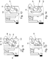
- the front connector 22 has the two narrow, preferably substantially plate-shaped connector plates 26 and 27, a spring 28, a latching member 29 and a bearing element 30 for the detachable mounting of the latching member 29 on the connector plates 26, 27.
- the spring 28 is on the two connector plates 26, 27 and causes the latching member 29 to be somewhat deflectable or pivotable about the longitudinal axis of the bearing element 30 and to be biased in a pivoting direction R1.
- the latching member 29 can be avoided in the pivoting direction R2 opposite to the pivoting direction R1.
- the evasibility is used to cancel a latching, which can be set up automatically by the latching member 29, with which the hanging component 25 can be latched on the front connector 22.
- the locking is released by manually pressing against one from the outside Operating section 29a on the locking member 29 against the force or spring action of the spring 28.
- the displacement element 31 associated with the lateral adjustment is accommodated.
- the adjusting element 24 which is rotatable from the outside about its longitudinal axis, is provided.
- the actuating element 24 engages transversely through openings in the outer housing 20, the inner housing 21, the two connector plates 26, 27 and the displacement element 31.
- the two connector plates 26, 27 are aligned parallel to one another and in a width direction B of the front connector 22 over a distance a (see FIG. Fig. 5 ) spaced apart from one another over the predominant extent and firmly connected to one another by elements not shown in concrete terms, such as, for example, two transverse bolts.
- elements not shown in concrete terms such as, for example, two transverse bolts.
- the longitudinal axes 32 of the elements or of the transverse bolts are shown in Fig. 4 indicated by dashed lines, each element being firmly connected with its two ends to the associated connector plate 26 and 27, respectively.
- the two elements are preferably aligned parallel to the width direction B or in particular parallel to the bearing element 30.
- An upper ramp 33 and a lower ramp 34 are provided on the front connector 22 at a distance from one another in a height direction H of the front connector 22.
- the flat ramps 33, 34 are oriented obliquely in a depth direction T of the front connector 22 and or in the direction away from a front side 35 of the front connector 22 sloping backwards or in the direction of a rear side 36 of the front connector 22.
- the upper ramp 33 has an upper narrow side 33a of the first connector plate 26 and an upper narrow side 33b of the second connector plate 27.
- the narrow sides 33a and 33b lie in a common, spanned first spatial plane.
- the lower ramp 34 has a lower narrow side 34a of the first connector plate 26 and a lower narrow side 34b of the second connector plate 27.
- the narrow sides 34a and 34b lie in a common, spanned second spatial plane which is parallel to the first spatial plane.
- the two upper narrow sides 33a and 33b are spaced apart from one another in the width direction B, as are the two lower narrow sides 34a and 34b.
- the two upper narrow sides 33a, 33b form a two-lane support 39 for the upper support section 37 of the hanging component 25 and the two lower narrow sides 34a and 34b form a two-lane support 40 for the lower supporting section 38 of the hanging component 25.
- the support sections 37 and 38 are preferably of the same type or identical.
- the support sections 37, 38 are preferably formed as pin-like or elongated components, here, for example, each as a pin or bolt with a concave or cylindrical outer shape. Other shapes such as B. a polygonal outer shape of the support portions 37, 38 are possible.
- the upper support section 37 slides along the two upper narrow sides 33a, 33b of the support 39 obliquely downwards in the sliding direction R (see FIG. Fig. 5 ) or in the direction of an end 53 of the cutouts 52.
- the lower support section 38 slides along the two lower narrow sides 34a, 34b of the support 40 when the drawer front 15 is connected to the drawer side parts 17, 18 obliquely downward in the sliding direction R or somewhat in the depth direction T and downwards against the height direction H.
- the sliding movement is supported by the weight of the drawer front 15.
- the lower ramp 34 is formed in each case by a slot-shaped cutout 52 in the connector plates 26 and 27.
- the lower ramp 34 is thus open to the front 35 of the front connector 22, so that the lower support section 38 can be threaded into the laterally aligned cutouts 52.
- the drawer front 15 comes into contact with the lower end area of the inside 15a in the area of a front lower edge of the drawer side part 17.
- the drawer front 15 is then lowered slightly, counter to the height direction H.
- the support section 38 is seated in a recess 54. This favors a correct spatial alignment of the drawer front 15 on the drawer side parts 17, 18.
- the support section 38 is in particular aligned such that the longitudinal axis of the support section 38 runs horizontally.
- the elements 20, 21, 23, 24 and 31 and a sliding element 31 on the front connector 22 serve for height adjustment and for side adjustment of the drawer front 15 on the rest of the drawer or on the drawer side parts 17 and 18.
- the inner housing 21 is advantageously U-shaped, with two opposite and spaced apart Side elements 61, 62.
- the side elements 61, 62 are advantageously present parallel to one another.
- the side elements 61, 62 are connected to one another at a distance via a central section 63, so that the inner housing 21 is U-shaped in a cross section.
- the inner housing 21 is advantageously designed as a bent sheet metal part.
- cylindrical guide elements 64, 65 connect the side elements 61, 62 to one another.
- the guide elements 64, 65 advantageously extend along their longitudinal axes between the side elements 61, 62.
- the guide elements 64, 65 are spaced apart from one another, in particular in a height direction H, on the inner housing 21, in particular in a positionally fixed or immovable manner.
- the connector plates 26, 27 advantageously have guide openings 66, 67, which are designed, for example, as longitudinal guides.
- the guide openings 66, 67 are preferably designed to match the guide elements 64, 65 of the inner housing 21.
- the guide elements 64, 65 are matched to the cylindrical guide openings 66, 67.
- the guide elements 64, 65 advantageously pass through the connector plates 26, 27 on the guide openings 66, 67, so that the front connector 22 is mounted on the inner housing 21 in a linearly displaceable manner.
- the displacement element 31 is advantageously plate-shaped and comprises a through opening 68, through which the actuating element 24 passes through the displacement element 31 in the assembled state.
- the through opening 68 is present, for example, as a cylindrical through opening.
- the actuating element 24 is advantageously designed like a screw.
- the adjusting element 24 is, for example, cylindrical and comprises a thread-like structure 70 on a cylinder jacket 69, which structure, for example, as a Thread is formed.
- the displacement element 31 has an engaging element 71.
- the engaging element 71 can, for example, also be designed to be complementary to the structure 70 of the actuating element 24, e.g. B. thread-like.
- the engaging element 71 protrudes tooth-like into the through opening 68 on the sliding element 31 and is designed to engage in the arranged state in the structure 70 of the adjusting element 24, so that a coupling of the adjusting element 24 and the sliding element 31 is established.
- the axially fixed actuating element 24 is rotated about its longitudinal axis, the displacing element 31 shifts to the left or right parallel to the width direction B depending on the direction of rotation of the actuating element 24.
- both the front connector 22 and the side elements 61, 62 of the inner housing 21 comprise slot-like recesses 72-75, through which the actuating element 24 extends.
- the recesses 72-75 are advantageously designed in such a way that the adjusting element 24 does not touch the recesses 72-75, in particular edge regions of the recesses 72-75, in any of the different positions of the different elements of the drawer front connecting device 9.
- the actuating element 24 is advantageously rotatably mounted on side parts 76, 77 of the outer housing 20.
- the side parts 76, 77 of the outer housing 20 are spaced apart, for example, and are formed opposite one another in parallel.
- the connector plates 26, 27 are advantageously formed on the respective inner sides 78, 79 in the manner of a slide bearing, so that the displacement element 31 between the connector plates 26, 27 is, for example, slidably mounted along a vertical extent H.
- friction surfaces of a friction structure 80 can be brought into abutment against one another and separated from one another again, so that friction effects due to abutting friction surfaces 81 change, in particular occur and disappear again, different exemplary embodiments of the invention are set out below.
- haptic and / or audible feedback is set up to an operator who operates or rotates the control element 24.
- the friction surfaces 81 of the friction structure 80 are formed on an axial lock 82 of the actuating element 24.
- the adjusting element 24 has a shaft 24a and a head 24b which is larger in diameter than the shaft 24a and which adjoins the shaft 24a at the front.
- the actuating element 24 is received in a rotatably guided manner with the head 24b, which engages in a receiving opening 83 in the side part 77 of the outer housing 20 which matches the head 24b.
- the shaft 24a extends through the inner housing 21 and the front connector 22, through the through opening 68 of the sliding element 31, and at the end engages through a receiving opening 84 in the side part 76 of the outer housing 20.
- the shaft 24a is at the outside with an end partial length of the shaft 24a a little bit over the side part 76.
- the actuating element 24 is secured by an edge 106 of the head 24b on the outside on the side part 77 against axial movement in a first axial direction A1.
- the axial securing means 82 is provided, which comprises a securing pin 85 which extends transversely to the longitudinal axis of the actuating element 24 through a corresponding bore 87 in the projecting partial length of the shaft 24a and is held therein .
- the locking pin 85 is longer than one Diameter of the projecting shaft 24a and projects on both sides outside of the shaft 24a in the radial direction with a first section 85a and a second section 85b.
- the securing pin 85 is cylindrical over its essential circumference and has a flat flat side 86 which extends in the longitudinal direction of the securing pin 85 and which is directed towards the side part 76.
- a first friction surface 81a of the friction structure 80 is formed on the first section 85a of the axial lock 82, which protrudes radially on the outside on the circumference of the actuating element, and a second friction surface 81b of the friction structure 80 is formed on the second section 85b of the axial lock 82 which projects radially on the outside of the setting element.
- the elevations 88 and depressions 89 are arranged regularly or are each formed with the same circumferential distance from one another and fixedly or in one piece on the outer housing 20.
- the elevations 88 and depressions 89 lie over a semicircle or distributed circumferentially around the receiving opening 84 at a short distance from the edge of the receiving opening 84, so that the elevations 88 are in frictional contact with the respective flat side 86 or, depending on the respective rotational position of the actuating element 24.
- the elevations can also be arranged on a circular line or over the entire circumferential section around the receiving opening 84.
- the locking pin 85 can then protrude radially either on one side or on both sides of the shaft 24a.
- the elevations can be arranged such that both friction surfaces 81a and 81b are in frictional contact with an associated elevation at the same time, or only ever one of the two friction surfaces 81a and 81b.
- the actuating element 24 is here provided in its rear end section of the shaft 24a with a circumferentially closed groove 90, which is designed such that the groove 90 is positioned within a receiving opening 91 in the side part 76 of the outer housing 20 in the inserted state.
- a circumferential groove base 92 is formed as a regular polygonal contour with a large number of flattened planar surfaces, which are equally flat here, for example eight contour surfaces 93, which are at an angle to one another.
- the receiving opening 91 is formed by a cutout in the sheet metal material of the side part 76 in such a way that two opposite webs 94, 95 of the sheet material delimited in the form of an arc on the front end protrude somewhat further inward than a remaining circular arc-shaped edge of the receiving opening 91.
- the groove base 92 and the webs 94 , 95 are coordinated in such a way that, when the adjusting element 24 is inserted, for example two contour surfaces 93 are present within the respective curved end face of the two webs 94, 95.
- the webs 94, 95 can be elastically deflected in order to push through the rear section of the shaft 24a of the adjusting element 24 which is larger in diameter to the groove base 92.
- the friction surfaces coming into frictional contact when the actuating element 24 is rotated are provided by sections of the contour surfaces 93 and by sections of the end faces of the two webs 94, 95.
- FIG. 8-10 Alternative advantageous embodiments of the invention, shown in the principle shown, show the Figures 11 to 17 .
- an actuating element 24 with a groove 90 and with a polygonal design of the groove base 92 and several identical contour surfaces 93 is shown in FIG Fig. 8 based on.
- the groove 90 is not offset within the receiving opening 84 in the side part 76, but so that the groove is then positioned in front of an outside of the side part 76.
- FIGS Fig. 8-10 The formation of the side part 76 in the area of the penetration of the adjusting element 24 is shown in FIGS Fig. 8-10 modified in each case, therefore only the formation of the side part 76 is discussed below.
- the counter-contour for bearing against opposite contour surfaces 93 is designed as a detachable and lockable tab 96 with a recess 97 on the outside of the side part 76, which can be locked with a locking arrangement 102.
- the recess 97 forms two somewhat deflectable arms 98, 99 which each bear against the inside of the contour surfaces 93 of the groove base 92.
- clips 100, 101 cut out and bent out of the material of the side part 76 are provided.
- Fig. 12 shows a variant with a pluggable tab 103 similar to that in FIG Fig. 11 without a locking arrangement 102.
- Yet another pluggable tab 104 shows Fig. 13 .
- An alternative tab 105 according to FIG Fig. 14 is not like according to the Fig. 11-13 horizontally attachable to the side part 76, but vertically attachable from below to the rear shaft section of the inserted adjusting element 24.
- the tabs 104 and 105 have a bent edge 106 or edge 107 for easier attachment and detachment from the side part 76.
- Fig. 15 are two opposite rectangular tabs 108, 109, each with two laterally cut-free spring sections for frontal contact with contour surfaces 93 externally attached to the side part 76, for. B. welded.
- a horizontally attachable tab 110 shows Fig. 16 , wherein the tab 110 has a two-armed wedge section 111 for clamping the tab 110 on the outside of the side part 76 when plugged in.
- a pluggable tab 112 which can be brought into frictional contact on one side or on the top side of the groove base 92 or on edges of the contour surfaces 93 is shown in FIG Fig. 17 shown.
- FIG. 18 shown alternative embodiment of the invention is on the side part 76 according to the variant Fig. 11 configured, the tab 96 for axial securing 82 and for haptic feedback is not yet attached to the side part 76.
- An adjusting element 113 differs from that in FIGS Fig. 3 , 7 and 10-17 Actuating elements 24 shown.
- the actuating element 113 with the contour surfaces 93 on the shaft 113a on the outer circumference of a head 113b has a polygonal outer contour with regular, similar and inclined to one another here, eight contour surfaces 114 in the manner of the contour surfaces 93. This serves an enhanced Feedback on the rotary movement of the adjusting element 113.
- the head 113b of the adjusting element when the adjusting element 113 is positioned correctly axially, is surrounded on the outside by a square opening 115 in the side part 77 of the outer housing 20.
- An axially extending edge is formed in each case between two adjacent contour surfaces 114, so that when the adjusting element 113 is rotated, individual edges come into frictional contact with flat opening walls 116 of the square opening 115 which are at right angles to one another.
- the eight contour surfaces 93 and the eight contour surfaces 114 are oriented identically to one another, only at different radial distances, since the head 113b and the groove base 92 are each arranged along a different circumference with respect to the central longitudinal axis of the actuating element 113. In this way, edges between contour surfaces 114 and edges between contour surfaces 93 each come into contact simultaneously with associated counter surfaces at the square opening 115 and the tab 96.
- a protruding web 118 On the rear end section of a shaft 117a of an adjusting element 117, a protruding web 118, which is axially aligned in section and has a tooth shape, alternately comes into contact with one of a plurality of projections 119 of a toothed ring-shaped counter-contour 120, which each has a recess 121 between two projections 119.
- the counter contour 120 is formed circumferentially on an edge of a through opening 122 in the side part 76 of the outer housing 20.
- an actuator 123 comprising an elongated shaft 123a and an end head 123b.
- the shaft 123a is over a partial length of the shaft 123a as in the other described adjusting elements according to the invention, a spiral thread 124 is formed.
- On a thread base 124a of the thread 124, a plurality of radially outwardly projecting, mutually identical lenticular or convex elevations 125 are formed as friction surfaces of the friction structure over the course of the thread 124, which are separated from one another by non-radially raised regions.
- the friction surfaces of the friction structure can, for example, have several elevations separated from one another on an actuating element such as, for. B. the actuator 123 on the circumferential or radial surfaces 126 and 127 on the head 123b or the surface 128 on the shaft 123a.
- an actuating element such as, for. B. the actuator 123 on the circumferential or radial surfaces 126 and 127 on the head 123b or the surface 128 on the shaft 123a.
- the friction surfaces such. B. Elevations can also be designed on the axial surfaces 129, 130 and / or 131 or on the oblique ring surfaces 132 or 133.
- the friction surfaces can also be present on the counter sections on the outer housing 20.
Landscapes
- Drawers Of Furniture (AREA)
Abstract
Description
- Im Möbelbereich sind Möbel mit einer Schublade, die relativ zu einem Korpus bewegbar sind bekannt, wobei an Schubladenseitenteilen ein Schubladenfrontbauteil über eine Schubladenfront-Verbindungsvorrichtung angebracht ist. Die Schubladenfront ist vorzugsweise lösbar bzw. austauschbar an den beiden Schubladenseitenteilen anbringbar.
- Die Befestigung der Schubladenfront an den Schubladenseitenteilen im Bereich von vorderen Stirnseiten der beiden Schubladenseitenteile, insbesondere wenn es sich um schwere bzw. große Fronten handelt, erfordert Geschick bzw. ist häufig schwierig. Darüber hinaus müssen im Verbindungszustand hohe Kräfte von der Verbindungsvorrichtung aufgenommen werden.
- Bisherige Schubladenfront-Verbindungsvorrichtungen sind außerdem hinsichtlich einer exakten Höhen- und/oder Seitenverstellung der Schubladenfront nur bedingt geeignet.
- Aufgabe der vorliegenden Erfindung ist es, eine Schubladenfront-Verbindungsvorrichtung der einleitend bezeichneten Art verbessert bereitzustellen, insbesondere im Hinblick auf eine einfache und exakte Höhen- und/oder Seitenverstellung der Schubladenfront.
- Diese Aufgabe wird durch die unabhängigen Ansprüche gelöst.
- In den abhängigen Ansprüchen sind zweckmäßige und vorteilhafte Weiterbildungen der Erfindung aufgezeigt.
- Die Erfindung geht aus von einer Schubladenfront-Verstellvorrichtung zur Verstellung einer Schubladenfront relativ zu einem Schubladenseitenteil in einer Verstellrichtung insbesondere zur Seitenverstellung der Schubladenfront.
- Der Kern der Erfindung liegt darin, dass die Schubladenfront-Verstellvorrichtung ein Gehäuse, einen Frontverbinder und ein durch ein Bedienen von außen drehbares Stellelement umfasst, wobei der Frontverbinder relativ zum Gehäuse versetzbar ist und durch Anbringen des Gehäuses an dem Schubladenseitenteil anordenbar ist, und wobei der Frontverbinder mit der Schubladenfront koppelbar ist, wobei der Frontverbinder durch die Bedienung des Stellelements relativ zum Gehäuse versetzbar ist, um den Frontverbinder in eine Versetzposition an dem Gehäuse von einer Mehrzahl von möglichen Versetzpositionen des Frontverbinders an dem Gehäuse zu bringen, so dass im angeordneten Zustand an dem Schubladenseitenteil das Versetzten des mit der Schubladenfront gekoppelten Frontverbinders die Verstellung der Schubladenfront bewirkt, wobei eine Reibstruktur mit Reibflächen am Stellelement und/oder an einem Gegenabschnitt an dem Gehäuse derart ausgebildet sind, dass mit fortschreitender Drehbewegung des Stellelements zumindest zwei Reibflächen aneinander in Anlage bringbar und wieder voneinander trennbar sind, so dass Reibeffekte durch aneinander anliegende Reibflächen sich ändern, insbesondere auftreten und wieder verschwinden, womit aufgrund der sich ändernden Reibeffekte während der Drehbewegung des Stellelements eine haptische und/oder hörbare Rückmeldung auf eine Bedienperson, welche das Stellelement bedient, eingerichtet ist. An einer Schublade sind in aller Regel genau zwei Schubladenseitenteile vorhanden, jeweils mit einem Frontverbinder an deren vorderen Stirnseite versenkt. Jeder Frontverbinder wirkt jeweils mit einem zugeordneten Einhängebauteil an der Schubladenfront zusammen. Demgemäß sind zwei Einhängebauteile an jeweils vorgegebener Stelle auf der Innenseite der Schubladenfront befestigt zum Beispiel angeschraubt.
- Die Schubladenfront-Verstellvorrichtung ist vorzugsweise als Höhenverstellvorrichtung für die Schubladenfront oder als Seitenverstellvorrichtung für die Schubladenfront ausgebildet. So wird im angeordneten Zustand der Schubladenfront an den Schubladenseitenteilen die Schubladenfront relativ zur verbleibenden Schublade in Höhenrichtung bzw. Seitenrichtung verstellt. Damit wird durch Versetzten des mit der Schubladenfront gekoppelten Frontverbinders die Verstellung der Schubladenfront in eine Höhenrichtung bzw. im Nutzzustand in vertikaler Richtung bzw. im Nutzzustand quer zur Vertikalen und in Seiten- bzw. Breitenrichtung der Schubladenfront bewirkt. Damit lässt sich insbesondere ein Frontbild des Möbels einrichten, so dass vordere Seitenränder der Schubladenfront zu benachbarten Schubladenfronten oder anderen Möbelkanten einstellbar ist. Im Ergebnis können am Möbel einheitlich gleiche Spaltbreiten zwischen Ränder der benachbarten Schubladenfronten und fluchtende Rändern der benachbarten Schubladenfronten oben und unten und rechts und links eingerichtet werden.
- Da es häufig für den Monteur schwierig ist, die Verstellung bzw. einen Verstellweg der Schubladenfront zu quantifizieren ist die vorgeschlagene Reibstruktur und die damit eingerichtete Rückmeldung an den Monteur während der Drehung des Stellelements zum Beispiel mit einem Schraubendrehwerkzeug vorteilhaft. Der Verstellweg zwischen zwei sich ändernden Reibeffekten beträgt vorzugsweise ein Bruchteil eines Millimeters zum Beispiel 0,2 bis 0,8 Millimeter, insbesondere zum Beispiel 0,5 Millimeter. Damit kann in beispielsweise 0,5 Millimeter-Schritten die Verstellung der Schubladenfront in der Höhe bzw. in der Seite bzw. in Breitenrichtung vorgenommen werden.
- Der Reibwiderstand beim Drehen des Stellelements bzw. gegen die von außen aufgezwungene Drehbewegung ist vorzugsweise alternierend stark und schwach spürbar für den Monteur beim Drehen des Stellelements. Vorzugsweise ist der Reibwiderstand abwechselnd deutlich spürbar und verschwindend bzw. nicht spürbar bzw. abwechselnd zunehmend und abnehmend spürbar. Die Verstellrichtung entspricht der Richtung der Drehachse, um welche das Stellelement drehbar ist. Bei einer Höhenverstellung weist das Stellelement eine senkrecht ausgerichtete Längsachse auf und in einer Seitenverstellung weist das Stellelement eine horizontal ausgerichtete Längsachse auf. Vorzugsweise ist die Längsachse des Stellelements in Richtung einer Breite der Schubladenfront bzw. in Seitenrichtung ausgerichtet.
- Durch ein Bedienen von außen durch z. B. einen Monteur wird das Stellelement gedreht, wahlweise in eine von beiden möglichen Drehrichtungen und davon abhängig nach oben oder unten bzw. nach rechts oder links verstellt. Der Frontverbinder ist demgemäß entlang einer bereitgestellten und durch Anschläge begrenzten Verstellstrecke des Frontverbinders hin- und herverstellbar. Der Frontverbinder ist vorzugsweise versetzbar am Gehäuse aufgenommen.
- Bevorzugt ist am Stellelement zumindest eine Reibfläche an einem Wirkabschnitt am Stellelement vorhanden, insbesondere sind mehrere Reibflächen entlang des Wirkabschnitt am Stellelement vorhanden, z. B. wenn am Gegenabschnitt genau eine Reibfläche ausgebildet ist. Bevorzugt ist an dem Gegenabschnitt zumindest eine Reibfläche an einem Wirkabschnitt am Gegenabschnitt vorhanden, insbesondere sind mehrere Reibflächen entlang eines Wirkabschnitts am Gegenabschnitt vorhanden, z. B. wenn am Stellelement genau eine Reibfläche ausgebildet ist. Zumindest einzelne der Reibflächen am Stellelement wirken mit zumindest einzelnen Reibflächen am Gegenabschnitt zusammen bzw. kommen aneinander in Reibanlage, abhängig von der Drehstellung des Stellelements am Gehäuse. Demgemäß sind die Reibflächen am Stellelement untereinander nicht in Reibanlage bringbar, ebenso sind die Reibflächen am Gegenabschnitt untereinander nicht in Reibanlage bringbar.
- Weiter ist es vorteilhaft, dass die Reibflächen einstückig am Gehäuse ausgebildet sind. Dies ist insbesondere herstellungstechnisch vorteilhaft. Vorzugsweise ist zusätzlich zumindest eine Reibfläche der Reibstruktur am Stellelement vorhanden, die auf die Reibfläche am Gehäuse abgestimmt ist.
- Ein anderer Vorteil ergibt sich, dass die Reibflächen einstückig am Stellelement ausgebildet sind. Eine oder mehrere einstückige Reibflächen am Stellelement sind vorteilhaft ausbildbar.
- Gemäß einer vorteilhaften Variante der Erfindung sind die Reibflächen alternierend mit benachbarten Zwischenbereichen ausgebildet.
Vorzugsweise ist entlang einer betrachteten Verstellstrecke der gesamte Verstellweg mit Reibflächen und Zwischenbereichen ausgebildet die alternierend vorhanden sind. Die Reibflächen sind alternierend entlang der Verstellstrecke bzw. eines Weges ausgebildet, der von den anderen Reibflächen überstrichen wird. Der Verstellweg verläuft insbesondere entlang eines zur Dreh- bzw. Längsachse des Stellelements umfänglichen Weges. - Damit kann über einen maximal bzw. insgesamt möglichen Drehweg des Stellelements immer eine Rückmeldung an den Monteur gegeben werden. Der Monteur erkennt dabei die regelmäßige Reibeffektänderung und weiß daher immer, wie weit die Drehbewegung bereits vorangeschritten ist und damit wie groß der seit Beginn der Drehbewegung zurückgelegte Verstellweg ist, also wie weit die Schubladenfront in der Höhenrichtung oder in der Breitenrichtung bereits verstellt ist.
- Auch ist es von Vorteil, wenn die Reibstruktur an einem axial zur Längsachse des Stellelements ausgerichteten Abschnitt am Stellelement ausgebildet ist. Das Stellelement weist vorzugsweise einen Kopf und einen daran anschließenden länglichen Schaft auf, wobei der Schaft ein geringeres Außenmaß bzw. einen geringeren Durchmesser als der Kopf aufweist. Am Kopf ist vorzugsweise ein Bedienabschnitt zum Ansetzen eines Abschnitts eines Bedien- bzw. Drehwerkzeugs zur Drehmomentübertragung ausgebildet z. B. eine Dreh-Eingriffkontur wie eine Schlitz- oder Kreuzschlitzkontur.
- Der axial ausgerichtete Abschnitt ist beispielsweise eine Stirnfläche an einem Schaft des Stellelements wie z. B. eine stirnseitige Endfläche des Stellelements. Auch kann der axial ausgerichtete Abschnitt eine Fläche eines Kopfes des Stellelements sein, zum Beispiel eine stirnseitige Oberseite des Stellelements oder eine der Oberseite gegenüberliegenden bzw. abgewandte Rück- bzw. Unterseite des Kopfabschnitts, der über den durchmesserkleineren Schaft übersteht. Der axial ausgerichtete Abschnitt kann auch an einem Absatz am Kopf und/oder am Schaft oder an einem Gewindegang des Stellelements ausgebildet sein.
- Nach einer weiteren Modifikation der Erfindung ist die Reibstruktur an einem umfänglich zur Längsachse des Stellelements ausgerichteten Abschnitt am Stellelement ausgebildet. Dies kann ebenfalls eine Außenseite wie eine zylindrische Mantelfläche eines Schraubelements sein. Der umfängliche Abschnitt kann auch ein Gewindegrund eines Gewindegangs am Stellelement sein.
- Bei einem zylindrischen Stellelement zum Beispiel einer Schraube mit zylindrischen Mantelflächen, die eine zylindrische Schaftmantelfläche oder eine zylindrische Kopfmantelfläche umfassen, ist die Reibstruktur auf zumindest einer dieser Flächen ausbildbar bzw. ausgebildet.
- An der Zylindermantelfläche ist die Reibstruktur bzw. deren Reibfläche zum Beispiel durch eine konvexe oder anders geformte Erhöhung wie Noppe, Zacke oder Rippe oder Steg zum Beispiel mit punktförmigem oder länglichem Umriss.
- Darüber hinaus ist es vorteilhaft, dass eine Reibfläche der Reibstruktur an einer Axialsicherung des Stellelements ausgebildet ist. Damit wird eine Doppelfunktion mit der Axialsicherung und der Rückmeldefunktion für den Monteur beim Drehen des Stellelements realisiert, was eine einfache und kompakte Bauweise ermöglicht.
- Die Axialsicherung dient insbesondere zur Sicherung der axialen Position des Stellelements am Gehäuse bzw. einem Aufnahmeabschnitt zur drehbaren Aufnahme des Stellelements. Die Axialsicherung kann zum Beispiel ein umfänglich zur Längsachse des Stellelements sich erstreckender umfänglich unterbrochener Sicherungselement umfassen, wie z. B. eine Klemmscheibe oder ein Sprengring, der in einer umfänglichen Nut außen am Stellelement insbesondere federnd lösbar eingerastet ist. Die Axialsicherung kann alternativ ein quer zur Längsachse des Stellelements ausgerichteter und durch dieses bzw. durch eine Durchgangsbohrung greifender Sicherungsstift umfassen, der einseitig oder beidseitig außen am Stellelement bzw. radial zur Längsachse des Stellelements übersteht.
- Gemäß einem Vorteil der Erfindung ist eine erste Reibfläche der Reibstruktur an einem ersten radial außen am Umfang des Stellelements überstehenden Abschnitt der Axialsicherung ausgebildet und eine zweite Reibfläche der Reibstruktur an einem zweiten radial außen am Umfang des Stellelements überstehenden Abschnitt der Axialsicherung ausgebildet. Dies ist kompakt bauend.
- Eine Ausgestaltung der Erfindung zeichnet sich dadurch aus, dass mehrere Reibflächen der Reibstruktur an einer Außenseite und/oder einer Innenseite des Gehäuses ausgebildet sind. Damit wird das Gehäuse nutzbar für die Reibflächen, was z. B. herstellungstechnisch vorteilhaft ist. Außerdem steht an dem Gehäuse eine Reihe von Bereichen zur Verfügung, welche an die Erfordernisse zur Bereitstellung der Reibflächen angepasst werden können.
- Außerdem ergibt sich ein Vorteil, wenn eine Reibfläche der Reibstruktur als Erhöhungsstruktur ausgebildet ist. Eine Erhöhungsstruktur ist in Form und Größe variabel ausbildbar. Durch die Erhöhungsform ist bereits durch die Form vorgebbar, dass eine sichere Reibanlage an einer Gegen-Reibfläche bei entsprechender Drehstellung des Stellelements erfolgt.
- Damit ist die Zuverlässigkeit der Rückmeldung durch die Reibstruktur vorteilhaft erhöht.
- Ein anderer Vorteil basiert darauf, dass die Reibstruktur mehrere umfänglich zur Längsachse des Stellelements angeordnete und voneinander in Umfangsrichtung getrennte Reibflächen umfasst. Dies ist eine vorteilhafte Ausbildung aufgrund der Relativbewegung des drehbaren Stellelements und des Gegenabschnitts, der in der Regel positionsfest ist.
- Auch vorteilhaft ist es, dass die Reibstruktur mehrere regelmäßig angeordnete Reibflächen umfasst. Damit kann ein hoher Informationsgehalt an den Monteur rückgemeldet werden, da aufgrund der Regelmäßigkeit ein sicherer Rückschluss auf den zurückgelegten Verstellweg gegeben ist.
- Insbesondere sind mehrere regelmäßig voneinander beabstandete Reibflächen vorhanden. Die Reibflächen sind in Verstellrichtung entlang des Verstellweges der mit dem Stellelement mitbewegbaren Reibflächen vorgesehen. Vorzugsweise sind die mehreren Reibflächen gleichartig bzw. identisch untereinander, jeweils für das Stellelement und den Gegenabschnitt betrachtet.
- Die Reibflächen am Gegenabschnitt umfassen z. B. voneinander in Umfangsrichtung zur Dreh- bzw. Längsachse des Stellelements getrennte Reibflächen. Die mehreren Reibflächen am Gegenabschnitt sind beispielsweise umfänglich zur Längsachse des Stellelements über den gesamten Umfang zur Längsachse des Stellelements oder vorzugsweise über einen Teilumfang zur Längsachse des Stellelements wie z. B. über den halben Umfang verteilt vorhanden.
- Vorteilhaft ist auch, wenn die Reibstruktur eine Reibfläche aufweist, die an einem Rand einer Durchgangsöffnung im Gehäuse ausgebildet ist, durch welche ein Abschnitt des Stellelements durchgreift. Damit ist platzsparend und sicher die Kontaktierung der betreffenden Reibflächen beim Drehen des Stellelements vorgebbar.
- Schließlich wird vorgeschlagen, dass die Reibstruktur eine Reibfläche umfasst, die an einem außenliegenden Abschnitt des Stellelements ausgebildet ist, wobei der außenliegende Abschnitt benachbart zu einem Rand einer Durchgangsöffnung im Gehäuse vorhanden ist, durch welche das Stellelement durchgreift. Auch dies ermöglicht eine kompakte und zuverlässige wirkende Anordnung der Reibstruktur.
- Zur Bereitstellung der Reibstruktur mit Reibflächen am Stellelement existiert eine Vielzahl von möglichen Ausgestaltungsbeispielen, zum Beispiel mit einer umfänglichen Nut außen auf einer axialen Stelle an einem Schaft des Stellelements. Ein Nutgrund der Nut weist vorzugsweise eine regelmäßige vieleckige Gestalt auf mit mehreren gleichen ebene Konturflächen auf, von denen benachbarte Konturflächen über Kanten voneinander getrennt sind. Die Kanten bilden jeweils Reibflächen, welche mit einer Gegenkontur zum Beispiel einer Kante einer Lasche an einem Seitenteil des Außengehäuses in Anlage und wieder außer Anlage bringbar ist beim Drehen des Stellelements in eine Drehrichtung.
- Auch ist ein zylindrischer Nutgrund mit beabstandeten Erhöhungen und Vertiefungen denkbar.
- Reibflächen durch an ebenen Abschnitten ausgebildete Erhöhungen sind zum Beispiel an einem Gewindegrund eines spiralförmigen Gewindeganges auf dem Schaft des Stellelements möglich und/oder an den Seitenflanken des Gewindeganges. Eine Gegenkontur wie ein Zahn eines Verschiebelements am Frontverbinder greift in den Gewindegang ein und wird je nach Drehung des Stellelements samt Frontverbinder zum Außengehäuse verstellt. Beim Drehen überstreichen die Erhöhungen den Zahn ratschend.
- Auch ein z. B. einzelner Steg außen am Schaft des Stellelements, der mit einer Zackenkontur an einem Rand einer Öffnung im Seitenteil des Außengehäuses zusammenwirkt, wobei der Schaft des Stellelements durch die Öffnung durchgreift, ist als Reibstruktur denkbar. Abhängig von der Drehung des Stellelements kommt der Steg in Reibanlage mit einem Zahn der Zahnkontur bzw. kommt davon wieder fei.
- Die Erfindung erstreckt sich zudem auf eine Schublade mit einer Schubladenfront und einem Schubladenseitenteil, wobei eine Schubladenfront-Verstellvorrichtung nach einer der vorbeschriebenen Ausführungen vorgesehen ist. Damit lassen sich die Vorteile an der Schublade beim Verstellen der Schubladenfront zur restlichen Schublade erzielen.
- Weitere Merkmale und Vorteile der Erfindung sind anhand von in den Figuren schematisch dargestellten Ausführungsbeispielen der Erfindung näher erläutert. Im Einzelnen zeigt:
- Fig. 1
- eine perspektivische Ansicht schräg von oben auf ein erfindungsgemäßes Möbel mit einer daran aufgenommenen und geöffnet dargestellten Schublade, wobei das Möbel ohne eine oberseitige Abdeckplatte gezeigt ist,
- Fig. 2
- die Schublade gemäß
Fig. 1 ohne eine Schubladenfront der Schublade in perspektivischer Ansicht, - Fig. 3
- ein vorderes Ende eines Schubladenseitenteils der Schublade gemäß
Fig. 2 mit einer erfindungsgemäßen Schubladenfront-Verbindungsvorrichtung in Explosionsdarstellung, - Fig. 3a
- ein Einhängebauteil der Schubladenfront-Verbindungsvorrichtung gemäß
Fig. 3 in einer perspektivischen Ansicht schräg von oben, - Fig. 4
- ein Frontverbinder der Schubladenfront-Verbindungsvorrichtung gemäß
Fig. 3 in Explosionsdarstellung, - Fig. 5
- der zusammengebaute Frontverbinder gemäß
Fig. 4 perspektivisch, - Fig. 6
- die verbundene Schubladenfront-Verstellvorrichtung in einer erfindungsgemäßen Variante,
- Fig. 7
- die Anordnung von
Fig. 6 von vorne im Ausschnitt ohne ein Einhängebauteil im Bereich eines Stellelements und - Fig. 8
- weitere erfindungsgemäße Anordnungen.
-
Fig. 1 zeigt ein Möbel 1 mit einer vorderseitig am Möbel 1 vorstehenden bzw. am Möbel 1 maximal weit herausbewegten erfindungsgemäßen Schublade 2. Die Schublade 2 ist bewegbar bzw. im gezeigten Möbelnutzzustand linear in horizontaler Richtung verschieblich über Führungsmittel 4 an einem Möbelkorpus 3 des Möbels 1 aufgenommen. Das Möbel 1 ist ein Kastenmöbel mit gegenüberliegenden Seitenwänden 5, 6, einem Boden 7, einer Rückwand 8 und zwei oberseitig vorhandenen Querbrettern 10, 11. - Das Querbrett 10 ist horizontal oben zwischen den beiden Seitenwänden 5, 6 im vorderen Bereich des Möbels 1 und das Querbrett 11 ist horizontal oben zwischen den beiden Seitenwänden 5, 6 im hinteren Bereich des Möbels 1 vorhanden, womit die beiden Seitenwände 5, 6, der Boden 7 und die Rückwand 8 stabil miteinander verbunden sind. Eine oberhalb der beiden Querbretter 10, 11 am Möbel 1 abdeckend vorzusehende Abdeckplatte ist nicht dargestellt.
- Die Führungsmittel 4 umfassen eine linke Schienenführung 13 und eine rechte Schienenführung 14, wobei die Schienenführungen 13, 14 zwischen dem Möbelkorpus 3 und der Schublade 2 wirken und zum Beispiel als Vollauszug 12 ausgebildet sind mit jeweils drei zueinander teleskopisch verschieblichen Schienen. Die zur Schienenführung 12 gespiegelt am Möbel 1 vorhandene rechte Schienenführung 14 ist in
Fig. 1 vollständig verdeckt. - Die Schublade 2 ist in
Fig. 2 in Alleindarstellung ohne eine Schubladenfront 15 dargestellt. Weitere Elemente der Schublade 2 sind ein Schubladenboden 16, ein linkes Schubladenseitenteil 17, ein rechtes Schubladenseitenteil 18 und eine Schubladenrückseite 19. - Die beiden gleichartigen Schubladenseitenteile 17 und 18 sind hier als Schubladenzargen bzw. als Hohlkammerzargen aus einem umgekanteten Blechmaterial gebildet. Die Schubladenseitenteile 17 und 18 sind an ihrem frontseitigen Ende 17a bzw. 18a offen und für die Verbindung mit der Schubladenfront 15 mittels jeweils einer erfindungsgemäßen Schubladenfront-Verbindungsvorrichtung 9 ausgestaltet. Für die Verbindung der Schubladenfront 15 mit dem Schubladenseitenteil 17 ist eine erste Schubladenfront-Verbindungsvorrichtung 9 vorgesehen und für die Verbindung der Schubladenfront 15 mit dem Schubladenseitenteil 18 ist eine zweite Schubladenfront-Verbindungsvorrichtung 9 vorgesehen. Die Verbindung der Schubladenfront 15 mit dem jeweiligen Schubladenseitenteil 17 bzw. 18 ist identisch eingerichtet bzw. mit jeweils einer identischen Schubladenfront-Verbindungsvorrichtung 9 realisiert, also mit zwei Schubladenfront-Verbindungsvorrichtungen 9 an der Schublade 2.
- In
Fig. 3 ist die Schubladenfront 15 nicht gezeigt, sondern lediglich ausschnittsweise umrissartig bzw. schematisch gestrichelt angedeutet. - Die als eine mehrteilige Baueinheit ausgestaltete Schubladenfront-Verbindungsvorrichtung 9 umfasst als Elemente ein Außengehäuse 20, ein Innengehäuse 21, einen Frontverbinder 22, Stellelemente 23, 24 und ein Einhängebauteil 25.
- Dabei sind die Elemente 20, 21, 22, 23 und 24 zusammengefasst in einem vertieften Aufnahmebereich am fronseitigen Ende 18a des Schubladenseitenteils 18 fest aber lösbar unterbringbar. Das Einhängebauteil 25 ist ausgebildet, an einer Innenseite 15a der Schubladenfront 15 fixiert zum Beispiel angeschraubt zu werden.
- Die Verbindung der Schubladenfront 15 mit den Schubladenseitenteilen 17 und 18 erfolgt über das jeweilige Zusammenwirken eines Einhängebauteils 25 mit einem dazugehörigen Frontverbinder 22. Hierfür ist an jedem Schubladenseitenteil 17, 18 jeweils frontseitig das Bauteil aus den zusammengefassten Elementen 20, 21, 22, 23 und 24 untergebracht. Diese Bauteile wirken für den Verbindungszustand mit einem jeweils zugeordneten Einhängebauteil 25 zusammen. Hierfür sind an der Innenseite 15a der Schubladenfront 15 genau zwei Einhängebauteile 25 an einer dafür abgestimmten Stelle fixiert.
- Die Verbindung erfolgt dann durch Einhängen der Schubladenfront 15 über die daran vorhandenen beiden Einhängebauteile 25 an den jeweiligen Frontverbindern 22 an den beiden Schubladenseitenteilen 17 und 18.
- Am Einhängebauteil 25 sind an einer Bauteilrückseite 42 eines Grundkörpers 41 des Einhängebauteils 25 Öffnungen 47, 48 und 49 zum Durchgreifen von nicht gezeigten Verbindungselementen wie Schrauben ausgebildet (s.
Fig. 3 ). Mit den Verbindungselementen ist das Einhängebauteil 25 an der Innenseite 15a anschraubbar. - Der vorzugsweise aus einem gebogenen bzw. gekanteten Blechmaterial gebildete Grundkörpers 41 des Einhängebauteil 25 umfasst außerdem an gegenüberliegenden Außenrändern der Bauteilrückseite 42 nach vorne vorstehende obere Seitenflanken 43, 44 und untere Seitenflanken 45, 46. Zwischen den oberen Seitenflanken 43, 44 ist ein oberer Stützabschnitt 37 aufgenommen und zwischen den unteren Seitenflanken 45, 46 ist ein unterer Stützabschnitt 38 aufgenommen. Beide Stützabschnitte 37 und 38 bzw. deren jeweilige zentrische Längsachse weisen den gleichen Abstand zur Bauteilrückseite 42 auf (. In Höhenrichtung H sind die beiden Stützabschnitte 37, 38 exakt übereinander bzw. fluchtend zueinander.
- Am Einhängebauteil 25 ist im Bereich des unteren Stützabschnitts 38 ein Erhebungsabschnitt 55 mit zwei sich fluchtend gegenüberliegenden Erhebungs-Teilabschnitten 56 und 57 vorhanden (s.
Fig. 3a ). Die zwei Erhebungs-Teilabschnitten 56 und 57 sind in Breitenrichtung B des Einhängebauteils 25 über einen Freiraum bzw. einen materialfreien Abstand c getrennt voneinander. Der Abstand c ist auf eine Abmessung einer Einhängekontur 50 bzw. deren Konturabschnitts 51 des Frontverbinders 22 insbesondere in einer Breitenrichtung B passend abgestimmt. Diese Breitenabmessung ist etwas geringer als die Breite des Frontverbinders 22, die durch die jeweilige flächige Außenseite von zwei Verbinderplatten 26 und 27 des Frontverbinders 22 vorgegeben ist. Hierfür weist der Konturabschnitt 51 zwei etwas nach innen aufeinander zu gebogene zahnförmige Abschnitte 58, 59 an der jeweiligen Verbinderplatte 26 und 27 auf. Die Abschnitte 58, 59 bilden eine Führungskante der Einhängekontur 50. - Die beiden Erhebungs-Teilabschnitten 56 und 57 sind vorzugsweise identisch und gleich lang. Der Erhebungs-Teilabschnitten 56 ist innenseitig an der Seitenflanke 45 vorstehend vorhanden und der Erhebungs-Teilabschnitten 57 ist innenseitig an der Seitenflanke 46 vorstehend vorhanden. Beispielhaft sind die Erhebungs-Teilabschnitte 56, 57 als Achsstummel mit zylindrischer Außenform und flacher gegebenenfalls leicht konvex gewölbter Stirnseite ausgestaltet.
- Der Frontverbinder 22 weist die zwei schmalen vorzugsweise im Wesentlichen plattenförmigen Verbinderplatten 26 und 27 auf, eine Feder 28, ein Rastorgan 29 und ein Lagerelement 30 für die ausweichbare Lagerung des Rastorgans 29 an den Verbinderplatten 26, 27. Die Feder 28 ist an den beiden Verbinderplatten 26, 27 aufgenommen und bewirkt, dass das Rastorgan 29 um die Längsachse des Lagerelements 30 etwas ausweichbar bzw. schwenkbar ist und in eine Schwenkrichtung R1 vorgespannt ist. In die zur Schwenkrichtung R1 entgegengesetzte Schwenkrichtung R2 ist das Rastorgan 29 ausweichbar. Die Ausweichbarkeit dient zur Aufhebung einer Verrastung, welche durch das Rastorgan 29 selbsttätig einrichtbar ist, womit das Einhängebauteil 25 am Frontverbinder 22 verrastbar ist. Die Aufhebung der Verrastung erfolgt durch manuelles Drücken von außen gegen einen Bedienabschnitt 29a am Rastorgan 29 gegen die Kraft- bzw. Federwirkung der Feder 28.
- Zwischen der ersten Verbinderplatte 26 und der zweiten Verbinderplatte 27 ist das zur Seitenverstellung gehörige Verschiebeelement 31 aufgenommen. Hierfür ist das um seine Längsachse von außen drehbare Stellelement 24 vorgesehen. Das Stellelement 24 greift hierfür quer durch darauf abgestimmte Öffnungen in dem Außengehäuse 20, dem Innengehäuse 21, den beiden Verbinderplatten 26, 27 und dem Verschiebeelement 31.
- Die beiden Verbinderplatten 26, 27 sind parallel zueinander ausgerichtet und in einer Breitenrichtung B des Frontverbinders 22 über einen Abstand a (s.
Fig. 5 ) über die überwiegende Erstreckung voneinander beabstandet und fest miteinander verbunden durch nicht konkret dargestellte Elemente wie beispielsweise zwei Querbolzen. Im oberen Bereich des Frontverbinders 22 ist ein plättchenförmiger Abstandshalter 60 mit der Breite a zwischen den Verbinderplatten 26 und 27 vorhanden. Die Längsachsen 32 der Elemente bzw. der Querbolzen sind inFig. 4 gestrichelt angedeutet, wobei jedes Element jeweils mit seinen beiden Enden an der dazugehörigen Verbinderplatte 26 bzw. 27 fest verbunden ist. Die beiden Elemente sind vorzugsweise parallel in Breitenrichtung B bzw. insbesondere parallel zum Lagerelement 30 ausgerichtet. - In einer Höhenrichtung H des Frontverbinders 22 beabstandet voneinander sind eine obere Rampe 33 und eine untere Rampe 34 am Frontverbinder 22 vorhanden. Die ebenen Rampen 33, 34 sind in einer Tiefenrichtung T des Frontverbinders 22 schräg ausgerichtet und bzw. in Richtung weg von einer Vorderseite 35 des Frontverbinders 22 nach hinten abfallend bzw. in Richtung einer Rückseite 36 des Frontverbinders 22 abfallend.
- Die obere Rampe 33 weist eine obere Schmalseite 33a der ersten Verbinderplatte 26 und eine obere Schmalseite 33b der zweiten Verbinderplatte 27 auf. Die Schmalseiten 33a und 33b liegen in einer gemeinsamen aufgespannten ersten Raumebene.
- Entsprechend weist die untere Rampe 34 eine untere Schmalseite 34a der ersten Verbinderplatte 26 und eine untere Schmalseite 34b der zweiten Verbinderplatte 27 auf. Die Schmalseiten 34a und 34b liegen in einer gemeinsamen aufgespannten zweiten Raumebene, die zur ersten Raumebene parallel liegt.
- Die beiden oberen Schmalseiten 33a und 33b sind mit dem Abstand a voneinander in Breitenrichtung B beabstandet, wie auch die beiden unteren Schmalseiten 34a und 34b.
- Die beiden oberen Schmalseiten 33a, 33b bilden eine zweispurige Abstützung 39 für den oberen Stützabschnitt 37 des Einhängebauteils 25 und die beiden unteren Schmalseiten 34a und 34b bilden eine zweispurige Abstützung 40 für den unteren Stützabschnitt 38 des Einhängebauteils 25.
- Die Stützabschnitte 37 und 38 sind vorzugsweise gleichartig bzw. identisch. Bevorzugt sind die Stützabschnitte 37, 38 als stiftartige bzw. längliche Bauteile gebildet, hier beispielsweise jeweils als Stift bzw. Bolzen mit konkaver bzw. zylindrischer Außenform. Auch andere Formen wie z. B. eine Mehrkant-Außenform der Stützabschnitte 37, 38 sind möglich.
- Beim Verbinden der Schubladenfront 15 mit den Schubladenseitenteilen 17, 18 rutscht der obere Stützabschnitt 37 entlang der beiden oberen Schmalseiten 33a, 33b der Abstützung 39 schräg nach unten in Rutschrichtung R (s.
Fig. 5 ) bzw. in Richtung eines Endes 53 der Ausschnitte 52. Entsprechend bzw. gleichzeitig rutscht der untere Stützabschnitt 38 entlang der beiden unteren Schmalseiten 34a, 34b der Abstützung 40 beim Verbinden der Schubladenfront 15 mit den Schubladenseitenteilen 17, 18 schräg nach unten in Rutschrichtung R bzw. etwas in die in Tiefenrichtung T und nach unten entgegen der Höhenrichtung H. Die Rutschbewegung wird durch das Eigengewicht der Schubladenfront 15 unterstützt. - Die untere Rampe 34 ist durch jeweils einen schlitzförmigen Ausschnitt 52 in den Verbinderplatten 26 und 27 gebildet. Damit ist die untere Rampe 34 zur Vorderseite 35 des Frontverbinders 22 offen, so dass der untere Stützabschnitt 38 in die seitlich fluchtenden Ausschnitte 52 einfädelbar ist. Die Schubladenfront 15 kommt mit dem unteren Endbereich der Innenseite 15a im Bereich einer frontseitigen Unterkante des Schubladenseitenteils 17 in Kontakt.
- Anschließend wird die Schubladenfront 15 geringfügig abgesenkt, entgegen der Höhenrichtung H. Dabei sitzt der Stützabschnitt 38 in einer Vertiefung 54 auf. Damit wird eine korrekte räumliche Ausrichtung der Schubladenfront 15 an den Schubladenseitenteilen 17, 18 begünstigt. Der Stützabschnitt 38 wird dabei insbesondere so ausgerichtet, dass die Längsachse des Stützabschnitts 38 horizontal verläuft.
- Die Elemente 20, 21, 23, 24 und 31 und ein Verschiebeelement 31 am Frontverbinder 22 dienen zur Höhenverstellung und zur Seitenverstellung der Schubladenfront 15 an der restlichen Schublade bzw. an den Schubladenseitenteilen 17 und 18.
- Das Innengehäuse 21 ist vorteilhafterweise U-förmig ausgebildet, mit zwei sich gegenüberliegend und voneinander beabstandeten Seitenelementen 61, 62. Die Seitenelemente 61, 62 sind vorteilhafterweise zueinander parallel ausgerichtet vorhanden. Beispielsweise sind die Seitenelemente 61, 62 über einen Mittelabschnitt 63 miteinander beabstandet verbunden, so dass das Innengehäuse 21 in einem Querschnitt U-förmig ausgebildet ist. Das Innengehäuse 21 ist vorteilhafterweise als ein Blechbiegeteil ausgebildet.
- Vorzugsweise zylindrische Führungselemente 64, 65 verbinden die Seitenelemente 61, 62 miteinander. Die Führungselemente 64, 65 erstrecken sich vorteilhafterweise entlang ihren Längsachsen zwischen den Seitenelementen 61, 62. Die Führungselemente 64, 65 sind voneinander beabstandet, insbesondere in einer Höhenrichtung H, am Innengehäuse 21 angeordnet, insbesondere positionsfest oder unbeweglich.
- Die Verbinderplatten 26, 27 besitzen vorteilhafterweise Führungsöffnungen 66, 67, welche beispielsweise als Längsführungen ausgebildet sind. Die Führungsöffnungen 66, 67 sind bevorzugterweise auf die Führungselemente 64, 65 des Innengehäuses 21 abgestimmt ausgebildet. Die Führungselemente 64, 65 sind auf die zylinderartigen Führungsöffnungen 66, 67 abgestimmt. Im angeordneten Zustand des Frontverbinders 22 am Innengehäuse 21 durchgreifen die Führungselemente 64, 65 vorteilhafterweise die Verbinderplatten 26, 27 an den Führungsöffnungen 66, 67, so dass der Frontverbinder 22 linear verschieblich am Innengehäuse 21 gelagert ist.
- Das Verschiebeelement 31 ist vorteilhafterweise plattenförmig ausgebildet und umfasst eine Durchgangsöffnung 68, durch welche das Stellelement 24 im montierten Zustand das Verschiebeelement 31 durchgreift. Die Durchgangsöffnung 68 ist beispielsweise als eine zylinderförmige Durchgangsöffnung vorhanden. Das Stellelement 24 ist vorteilhafterweise schraubenartig ausgebildet. Das Stellelement 24 ist beispielsweise zylinderförmig ausgebildet und umfasst auf einem Zylindermantel 69 eine gewindeartige Struktur 70, welche beispielsweise als ein Gewinde ausgebildet ist. Um das Stellelement 24 mit dem Verschiebeelement 31 zu koppeln besitzt das Verschiebeelement 31 ein Eingreifelement 71. Das Eingreifelement 71 kann beispielsweise ebenfalls entsprechend komplementär zur Struktur 70 des Stellelements 24 ausgebildet sein, z. B. gewindeartig. Denkbar ist aber auch, wie in
Figur 4 dargestellt, dass das Eingreifelement 71 zahnartig in die Durchgangsöffnung 68 am Verschiebeelement 31 hineinragt und derart ausgebildet ist, im angeordneten Zustand in die Struktur 70 des Stellelements 24 einzugreifen, so dass eine Kopplung von Stellelement 24 und Verschiebeelement 31 eingerichtet ist. Beim Drehen des axial fixierten Stellelements 24 um seine Längsachse verschiebt sich das Verschiebeelement 31 je nach Drehrichtung des Stellelements 24 nach links oder rechts parallel zur Breitenrichtung B. - Um das Stellelement 24 am Verschiebeelement 31 anordnen zu können, umfassen sowohl der Frontverbinder 22 als auch die Seitenelemente 61, 62 des Innengehäuses 21 schlitzartige Ausnehmungen 72-75, durch welche das Stellelement 24 durchgreift. Die Ausnehmungen 72-75 sind vorteilhafterweise derart ausgebildet, dass das Stellelement 24 die Ausnehmungen 72-75, insbesondere Randbereiche der Ausnehmungen 72-75 in keiner der unterschiedlichen Stellpositionen der verschiedenen Elemente der Schubladenfront-Verbindungsvorrichtung 9 zueinander berührt.
- Das Stellelement 24 ist vorteilhafterweise an Seitenteilen 76, 77 des Außengehäuses 20 drehbar gelagert. Die Seitenteile 76, 77 des Außengehäuses 20 sind beispielsweise voneinander beabstandet und sich parallelgegenüberliegend ausgebildet.
- Die Verbinderplatten 26, 27 sind an jeweiligen Innenseiten 78, 79 vorteilhafterweis gleitlagerartig ausgebildet, so dass das Verschiebeelement 31 zwischen den Verbinderplatten 26, 27 entlang einer Höhenerstreckung H beispielsweise gleitend gelagert ist.
- Damit mit fortschreitender Drehbewegung des Stellelements 24 Reibflächen einer Reibstruktur 80 aneinander in Anlage bringbar und wieder voneinander trennbar sind, so dass Reibeffekte durch aneinander anliegende Reibflächen 81 sich ändern, insbesondere auftreten und wieder verschwinden, sind nachfolgend unterschiedliche Ausführungsbeispiel der Erfindung dargelegt.
- Dabei ist aufgrund sich ändernder Reibeffekte während der Drehbewegung des Stellelements 24 eine haptische und/oder hörbare Rückmeldung auf eine Bedienperson, welche das Stellelement 24 bedient bzw. verdreht, eingerichtet.
- Gemäß der
Fig. 6 und 7 , welche die zusammengebaute Schubladenfront-Verstellvorrichtung 9 zeigt, sind die Reibflächen 81 der Reibstruktur 80 an einer Axialsicherung 82 des Stellelements 24 ausgebildet. Das Stellelement 24 weist einen Schaft 24a und einen zum Schaft 24a durchmessergrößeren Kopf 24b auf, der sich vorne an den Schaft 24a anschließt. Das Stellelement 24 ist mit dem Kopf 24b, der in eine zum Kopf 24b passenden Aufnahmeöffnung 83 im Seitenteil 77 des Außengehäuses 20 greift, drehbar geführt aufgenommen. Der Schaft 24a erstreckt sich durch das Innengehäuse 21 und den Frontverbinder 22, durch die Durchgangsöffnung 68 des Verschiebeelements 31, und greift am Ende durch eine Aufnahmeöffnung 84 im Seitenteil 76 des Außengehäuses 20. Der Schaft 24a steht mit einer endseitigen Teillänge des Schaftes 24a außen an dem Seitenteil 76 etwas über. - Das Stellelement 24 ist durch Anlage eines Randes 106 des Kopfes 24b außen an dem Seitenteil 77 gegen eine axiale Bewegung in eine erste Axialrichtung A1 gesichert. Zur Sicherung des Stellelements 24 gegen eine axiale Bewegung in eine zweite Axialrichtung A2 ist die Axialsicherung 82 vorgesehen, welche einen Sicherungsstift 85 umfasst, der quer zur Längsachse des Stellelements 24 durch eine entsprechende Bohrung 87 in der überstehenden Teillänge des Schaftes 24a reicht und darin festgehalten ist. Der Sicherungsstift 85 ist länger als ein Durchmesser des überstehenden Schaftes 24a und steht beidseitig außen an dem Schaft 24a in radialer Richtung mit einem ersten Abschnitt 85a und einem zweiten Abschnitt 85b über. Der Sicherungsstift 85 ist über seinen wesentlichen Umfang zylindrisch und weist eine in Längsrichtung des Sicherungsstifts 85 verlaufende ebene Flachseite 86 auf, die zum Seitenteil 76 gerichtet ist.
- Eine erste Reibfläche 81a der Reibstruktur 80 ist an dem ersten radial außen am Umfang des Stellelements überstehenden Abschnitt 85a der Axialsicherung 82 ausgebildet und eine zweite Reibfläche 81b der Reibstruktur 80 ist an dem zweiten radial außen am Umfang des Stellelements überstehenden Abschnitt 85b der Axialsicherung 82 ausgebildet.
- Als Gegen-Reibflächen zu der ersten Reibfläche 81a und zu der zweiten Reibfläche 81b sind mehrere voneinander über Vertiefungen 89 getrennte Erhöhungen 88 an der Außenseite des Seitenteils 76 vorhanden. Die Erhöhungen 88 und Vertiefungen 89 sind regelmäßig angeordnet bzw. mit jeweils gleichem umfänglichen Abstand zueinander und fest bzw. einstückig an dem Außengehäuse 20 ausgebildet. Die Erhöhungen 88 und Vertiefungen 89 liegen über eine Halbkreislinie bzw. umfänglich verteilt um die Aufnahmeöffnung 84 mit einem geringen Abstand zum Rand der Aufnahmeöffnung 84, so dass die Erhöhungen 88 abhängig von der jeweiligen Drehstellung des Stellelements 24 in Reibkontakt mit der jeweiligen Flachseite 86 bzw. mit der ersten Reibfläche 81a oder mit der zweiten Reibfläche 81b über einen geringen überstrichenen Drehwinkel des Stellelements 24 von zum Beispiel 10 bis 20 Winkelgraden aneinander in Anlage-Reibkontakt gelangen. Dabei wird durch elastische Eigenschaften der betreffenden Abschnitte bzw. Bauteile das Verdrehen des Stellelements 24 nicht blockiert, sondern mit einem manuell problemlos aufbringbaren Drehmoment der wirkende Widerstand aufgrund der Erhöhungen 88 überwunden, bis die Reibfläche 81a bzw. 81b unter Beibehaltung der Drehrichtung die betreffende Erhöhung überstrichen hat und der Reibkontakt bzw. Reibwiderstand aufgrund der nach der Erhöhung folgenden Vertiefung 89 verringert bzw. aufgehoben ist. Beim Weiterdrehen des Stellelements 24 kommt die jeweilige Reibfläche 81a oder 81b in Reibkontakt mit der in Drehrichtung nächsten Erhöhung 88 und so weiter. Damit wird über kurze Verstellweg-Intervalle des Frontverbinders 22 von z. B. einem halben Millimeter eine haptische und/oder hörbare Rückmeldung über den Verstellweg des Frontverbinders 22 und damit der an der restlichen Schublade 2 montierten Schubladenfront 15 an den Monteur beim Verdrehen des Stellelements 24 rückgekoppelt. Die beschriebenen Zusammenhänge wirken identisch in beide Verstellrichtungen des Frontverbinders 22 in Breitenrichtung B bzw. in beide Drehrichtungen des Stellelements 24. Je nach Drehstellung des Stellelements 24 kommt entweder die Reibfläche 81a oder die radial gegenüberliegende Reibfläche 81b in Kontakt mit einer Erhöhung 88, weshalb die Erhöhungen 88 nur über einen Halbkreis-Abschnitt umfänglich zum Rand der Aufnahmeöffnung 84 ausgebildet sind. Alternativ können die Erhöhungen auch auf einer Kreislinie bzw. über den gesamten Umfangsabschnitt um die Aufnahmeöffnung 84 herum angeordnet sein. Der Sicherungsstift 85 kann dann entweder einseitig oder beidseitig am Schaft 24a radial überstehen. Bei beidseitigem Überstand können die Erhöhungen so angeordnet sein, dass beide Reibfläche 81a und 81b gleichzeitig an jeweils einer zugeordneten Erhöhung in Reibkontakt sind oder immer nur genau eine der beiden Reibflächen 81a und 81b.
- Alternative Reibstrukturen 80 zeigen die weiteren Figuren, wobei immer das gleiche Grundprinzip der im Verlauf der Drehbewegung des Stellelements 24 aneinander in Anlage und wieder voneinander freikommenden Reibflächen 81 verwirklicht ist.
- Weitere erfindungsgemäße Anordnungen mit einer Axialsicherung zeigen die
Figuren 8 bis 21 . - Das Stellelement 24 ist hierbei in seinem hinteren Endabschnitt des Schafts 24a mit einer umfänglich geschlossen verlaufenden Nut 90 versehen, die so ausgebildet ist, dass die Nut 90 im eingesteckten Zustand innerhalb einer Aufnahmeöffnung 91 im Seitenteil 76 des Außengehäuses 20 positioniert ist. Ein umfänglich umlaufender Nutgrund 92 ist als regelmäßige Vieleckkontur mit einer Vielzahl abgeflachter ebener untereinander gleichflächige hier beispielhaft acht Konturflächen 93 gebildet, die winklig zueinander stehen. Die Aufnahmeöffnung 91 ist durch eine Ausschneidung im Blechmaterial des Seitenteils 76 derart gebildet, dass zwei gegenüberliegenden stirnseitig kreisbogenförmig begrenzte Stege 94, 95 des Blechmaterials etwas weiter nach innen vorstehen als ein verbleibender kreisbogenausschnitt-förmiger Rand der Aufnahmeöffnung 91. Der Nutgrund 92 und die Stege 94, 95 sind so abgestimmt, dass bei eingesteckten Stellelement 24 zum Beispiel zwei Konturflächen 93 innerhalb der jeweiligen gebogenen Stirnseite der beiden Stege 94, 95 anstehen. Damit wird beim Verdrehen des Stellelements 24 die Rückkopplung an den Monteur realisiert, da mit dem Vorbeistreifen der Konturflächen 93 an den Stegen 94, 95 abwechselnd ein Reibwiderstand zwischen diesen Abschnitten zu- und abnimmt. Die Stege 94, 95 sind zum Durchstecken des hinteren zum Nutgrund 92 durchmessergrößeren Abschnitts des Schafts 24a des Stellelements 24 elastisch ausweichbar. Die aneinander in Reibkontakt beim Drehen des Stellelements 24 kommende Reibflächen sind durch Abschnitte der Konturflächen 93 und durch Abschnitte der Stirnseiten der beiden Stege 94, 95 bereitgestellt.
- Weitere nach dem in den
Fig. 8-10 dargestellten Prinzip ausgestaltete alternative vorteilhafte Ausbildungen der Erfindung zeigen dieFiguren 11 bis 17 . Dabei ist jeweils ein Stellelement 24 mit einer Nut 90 und mit vieleckiger Gestaltung des Nutgrunds 92 und mehreren gleichen Konturflächen 93 gemäßFig. 8 zugrundegelegt. Die Nut 90 ist im eingesteckten Zustand des Stellelements 24 nicht innerhalb der Aufnahmeöffnung 84 im Seitenteil 76 sondern dazu versetzt, so dass die Nut anschließend zu bzw. außen vor einer Außenseite des Seitenteils 76 positioniert ist. - Die Ausbildung des Seitenteils 76 im Bereich der Durchgreifung des Stellelements 24 ist in den
Fig. 8-10 jeweils abgewandelt, daher wird nachfolgend allein auf die Ausbildung des Seitenteils 76 eingegangen. - Gemäß
Fig. 11 ist die Gegenkontur zur Anlage an gegenüberliegenden Konturflächen 93 als lösbar und mit einer Arretieranordnung 102 arretierbar außen am Seitenteil 76 ansteckbare Lasche 96 mit einer Ausnehmung 97 ausgestaltet. Die Ausnehmung 97 bildet zwei etwas ausweichbare Arme 98, 99 die jeweils innen an den Konturflächen 93 des Nutgrunds 92 anliegen. Zur seitlichen bzw. oberseitigen und unterseitigen Führung der Lasche 96 beim Anbringen und zum Halten der Lasche 96 sind aus dem Material des Seitenteils 76 freigeschnittene und herausgebogene Klammern 100, 101 vorgesehen. -
Fig. 12 zeigt eine Variante mit einer steckbaren Lasche 103 ähnlich wie inFig. 11 ohne eine Arretieranordnung 102. - Eine wieder andere steckbare Lasche 104 zeigt
Fig. 13 . - Eine alternative Lasche 105 gemäß
Fig. 14 ist nicht wie gemäß derFig. 11-13 horizontal ansteckbar an dem Seitenteil 76, sondern vertikal von unten ansteckbar am hinteren Schaftabschnitt des eingesteckten Stellelements 24. Die Laschen 104 und 105 weisen einen umgebogenen Rand 106 bzw. Rand 107 auf zum leichteren Anstecken und wieder Lösen vom Seitenteil 76. - Bei der Erfindungsvariante gemäß
Fig. 15 sind zwei gegenüberliegende rechteckige Laschen 108, 109 mit jeweils zwei seitlich freigeschnittenen Federabschnitten zur stirnseitigen Anlage an Konturflächen 93 außen am Seitenteil 76 stoffschlüssig angebracht z. B. angeschweißt. - Eine horizontal ansteckbare Lasche 110 zeigt
Fig. 16 , wobei die Lasche 110 einen zweiarmigen Keilabschnitt 111 zum Verklemmen der Lasche 110 außen am Seitenteil 76 im angesteckten Zustand aufweist. - Eine einseitig bzw. oberseitig am Nutgrund 92 bzw. an Kanten der Konturflächen 93 in Reib-Anlage bringbare steckbare Lasche 112 ist in
Fig. 17 dargestellt. - Die in
Fig. 18 gezeigte alternative erfindungsgemäße Ausbildung ist am Seitenteil 76 gemäß der Variante ausFig. 11 ausgestaltet, wobei die Lasche 96 zur Axialsicherung 82 und zur haptischen Rückmeldung noch nicht aufgesteckt ist am Seitenteil 76. Ein Stellelement 113 unterscheidet sich von den in denFig. 3 ,7 und10-17 gezeigten Stellelementen 24. Das Stellelement 113 weist zusätzlich zur oben beschriebenen Nut 90 mit den Konturflächen 93 am Schaft 113a am Außenumfang eines Kopfes 113b eine Vieleck-Außenkontur mit regelmäßigen gleichartigen und zueinander geneigten hier beispielhaft acht Konturflächen 114 in der Art der Konturflächen 93 auf. Dies dient einer verstärkten Rückmeldung bei der Drehbewegung des Stellelements 113. Der Kopf 113b des Stellelements ist bei axial richtig positioniertem Stellelement 113 außenumfänglich von einer Vierecköffnung 115 in dem Seitenteil 77 des Außengehäuses 20 umgeben. - Zwischen zwei benachbarten Konturflächen 114 ist jeweils eine axial verlaufende Kante gebildet, so dass beim Drehen des Stellelements 113 einzelne Kanten in Reibkontakt mit flächigen, rechtwinklig zueinander stehenden Öffnungswandungen 116 der Vierecköffnung 115 gelangen. Die acht Konturflächen 93 und die acht Konturflächen 114 sind zueinander identisch ausgerichtet, lediglich auf unterschiedlichen radialen Abständen, da der Kopf 113b und der Nutgrund 92 bezogen zur zentralen Längsachse des Stellelements 113 jeweils entlang eines anderen Umfangs angeordnet sind. Damit kommen Kanten zwischen Konturflächen 114 und Kanten zwischen Konturflächen 93 jeweils simultan in Anlage an dazugehörigen Gegenflächen an der Vierecköffnung 115 und der Lasche 96.
- Nach der erfindungsgemäßen Variante aus
Fig. 19 kommt ein am hinteren Endabschnitt eines Schaftes 117a eines Stellelements 117 axial ausgerichteter im Schnitt zahnförmiger vorstehender Steg 118 beim Drehen des Stellelements 117 abwechselnd in Anlage an einem von mehreren Vorsprüngen 119 einer zahnkranzförmigen Gegenkontur 120, welche zwischen zwei Vorsprüngen 119 jeweils eine Vertiefung 121 aufweist. Die Gegenkontur 120 ist umfänglich an einem Rand einer Durchgangsöffnung 122 in dem Seitenteil 76 des Außengehäuses 20 ausgebildet. - Schließlich ist anhand der
Fig. 20 und 21 eine Alternative der Erfindung dargestellt mit einem Stellelement 123, umfassend einen länglichen Schaft 123a und einen endseitigen Kopf 123b. Im Schaft 123a ist über eine Teillänge des Schaftes 123a wie bei den anderen beschriebenen Stellelementen gemäß der Erfindung ein spiralförmig verlaufender Gewindegang 124 ausgebildet. An einem Gewindegrund 124a des Gewindegangs 124 sind als Reibflächen der Reibstruktur über den Verlauf des Gewindegangs 124 mehrere radial nach außen vorstehende, untereinander gleiche linsenförmige bzw. konvexe Erhöhungen 125 ausgebildet, die voneinander über nicht radial erhöhte Bereiche getrennt sind. Abhängig von der Drehstellung des Stellelements 123 kommt kurzzeitig jeweils eine der Erhöhungen 125 in Anlage an dem Eingreifelement 71 an dem Verschiebeelement 31. Damit wird beim Drehen des Stellelements 123 eine haptische bzw. akustische Rückmeldung an den Monteur gegeben. - Grundsätzlich können die Reibflächen der Reibstruktur zum Beispiel mehrere voneinander getrennte Erhöhungen an einem Stellelement wie z. B. dem Stellelement 123 an den umfänglichen bzw. radialen Flächen 126 und 127 am Kopf 123b oder der Fläche 128 am Schaft 123a vorhanden sein.
- Die Reibflächen wie z. B. Erhöhungen können auch an den axialen Flächen 129, 130 und/oder 131 bzw. an den schrägen Ringflächen 132 oder 133 ausgestaltet sein.
- Entsprechend können die Reibflächen auch an den Gegenabschnitten am Außengehäuse 20 vorhanden sein.
- Denkbar ist auch, dass die Reibflächen wie z. B. Erhöhungen an zumindest einer Flanke von gegenüberliegenden spiralförmigen Flanken 134, 135 des Gewindegangs 124 ausgeformt sind.
-
- 1
- Möbel
- 2
- Schublade
- 3
- Möbelkorpus
- 4
- Führungsmittel
- 5
- Seitenwand
- 6
- Seitenwand
- 7
- Boden
- 8
- Rückwand
- 9
- Schubladenfront-Verbindungsvorrichtung
- 10
- Querbrett
- 11
- Querbrett
- 12
- Vollauszug
- 13
- Schienenführung
- 14
- Schienenführung
- 15
- Schubladenfront
- 15a
- Innenseite
- 16
- Schubladenboden
- 17
- Schubladenseitenteil
- 17a
- Ende
- 18
- Schubladenseitenteil
- 18a
- Ende
- 19
- Schubladenrückseite
- 20
- Außengehäuse
- 21
- Innengehäuse
- 22
- Frontverbinder
- 23
- Stellelement
- 24
- Stellelement
- 24a
- Schaft
- 24b
- Kopf
- 25
- Einhängebauteil
- 26
- Verbinderplatte
- 27
- Verbinderplatte
- 28
- Feder
- 29
- Rastorgan
- 29a
- Bedienabschnitt
- 29b
- Vorsprung
- 30
- Lagerelement
- 31
- Verschiebeelement
- 32
- Längsachse
- 33
- Rampe
- 33a
- Schmalseite
- 33b
- Schmalseite
- 34
- Rampe
- 34a
- Schmalseite
- 34b
- Schmalseite
- 35
- Vorderseite
- 36
- Rückseite
- 37
- Stützabschnitt
- 38
- Stützabschnitt
- 39
- Abstützung
- 40
- Abstützung
- 41
- Grundkörper
- 42
- Bauteilrückseite
- 43
- Seitenflanke
- 44
- Seitenflanke
- 45
- Seitenflanke
- 46
- Seitenflanke
- 47
- Öffnung
- 48
- Öffnung
- 49
- Öffnung
- 50
- Einhängekontur
- 51
- Konturabschnitt
- 52
- Ausschnitt
- 53
- Ende
- 54
- Vertiefung
- 55
- Erhebungsabschnitt
- 56
- Erhebungs-Teilabschnitt
- 57
- Erhebungs-Teilabschnitt
- 58
- Abschnitt
- 59
- Abschnitt
- 60
- Abstandhalter
- 61
- Seitenelement
- 62
- Seitenelement
- 63
- Mittelabschnitt
- 64
- Führungselement
- 65
- Führungselement
- 66
- Führungsöffnung
- 67
- Führungsöffnung
- 68
- Durchgangsöffnung
- 69
- Zylindermantel
- 70
- Struktur
- 71
- Eingreifelement
- 72
- Ausnehmung
- 73
- Ausnehmung
- 74
- Ausnehmung
- 75
- Ausnehmung
- 76
- Seitenteil
- 77
- Seitenteil
- 78
- Innenseite
- 79
- Innenseite
- 80
- Reibstruktur
- 81
- Reibfläche
- 81a
- Reibfläche
- 81b
- Reibfläche
- 82
- Axialsicherung
- 83
- Aufnahmeöffnung
- 84
- Aufnahmeöffnung
- 85
- Sicherungsstift
- 85a
- Abschnitt
- 85b
- Abschnitt
- 86
- Flachseite
- 87
- Bohrung
- 88
- Erhöhung
- 89
- Vertiefung
- 90
- Nut
- 91
- Aufnahmeöffnung
- 92
- Nutgrund
- 93
- Konturfläche
- 94
- Steg
- 95
- Steg
- 96
- Lasche
- 97
- Ausnehmung
- 98
- Arm
- 99
- Arm
- 100
- klammer
- 101
- Klammer
- 102
- Arretieranordnung
- 103
- Lasche
- 104
- Lasche
- 105
- Lasche
- 106
- Rand
- 107
- Rand
- 108
- Lasche
- 109
- Lasche
- 110
- Lasche
- 111
- Keilabschnitt
- 112
- Lasche
- 113
- Stellelement
- 113a
- Schaft
- 113b
- Kopf
- 114
- Konturfläche
- 115
- Vierecköffnung
- 116
- Öffnungswandung
- 117
- Stellelement
- 117a
- Schaft
- 118
- Steg
- 119
- Vorsprung
- 120
- Gegenkontur
- 121
- Vertiefung
- 122
- Durchgangsöffnung
- 123
- Stellelement
- 123a
- Schaft
- 123b
- Kopf
- 124
- Gewindegang
- 124a
- Gewindegrund
- 125
- Erhöhung
- 126
- Fläche
- 127
- Fläche
- 128
- Fläche
- 129
- Fläche
- 130
- Fläche
- 131
- Fläche
- 132
- Ringfläche
- 133
- Ringfläche
- 134
- Flanke
- 135
- Flanke
Claims (15)
- Schubladenfront-Verstellvorrichtung (9) zur Verstellung einer Schubladenfront (15) relativ zu einem Schubladenseitenteil (17, 18) in einer Verstellrichtung zur Verstellung der Schubladenfront (15), insbesondere zur Seitenverstellung, dadurch gekennzeichnet, dass die Schubladenfront-Verstellvorrichtung (9) ein Gehäuse (20), einen Frontverbinder 22) und ein durch ein Bedienen von außen drehbares Stellelement (24, 113, 117, 123) umfasst, wobei der Frontverbinder (22) relativ zum Gehäuse (20) versetzbar ist und durch Anbringen des Gehäuses (20) an dem Schubladenseitenteil (17, 18) anordenbar ist, und wobei der Frontverbinder (22) mit der Schubladenfront (15) koppelbar ist, wobei der Frontverbinder (22) durch die Bedienung des Stellelements (24, 113, 117, 123) relativ zum Gehäuse (20) versetzbar ist, um den Frontverbinder (22) in eine Versetzposition an dem Gehäuse von einer Mehrzahl von möglichen Versetzpositionen des Frontverbinders (22) an dem Gehäuse zu bringen, so dass im angeordneten Zustand an dem Schubladenseitenteil das Versetzten des mit der Schubladenfront gekoppelten Frontverbinders (22) die Verstellung der Schubladenfront bewirkt, wobei eine Reibstruktur (80) mit Reibflächen (81) am Stellelement (24, 113, 117, 123) und/oder an einem Gegenabschnitt an dem Gehäuse (20) derart ausgebildet sind, dass mit fortschreitender Drehbewegung des Stellelements (24, 113, 117, 123) zumindest zwei Reibflächen (81) aneinander in Anlage bringbar und wieder voneinander trennbar sind, so dass Reibeffekte durch aneinander anliegende Reibflächen (81) sich ändern, insbesondere auftreten und wieder verschwinden, womit aufgrund der sich ändernden Reibeffekte während der Drehbewegung des Stellelements (24, 113, 117, 123) eine haptische und/oder hörbare Rückmeldung auf eine Bedienperson, welche das Stellelement (24, 113, 117, 123) bedient, eingerichtet ist.
- Schubladenfront-Verstellvorrichtung nach Anspruch 1, dadurch gekennzeichnet, dass die Reibflächen (81) einstückig am Gehäuse (20) ausgebildet sind.
- Schubladenfront-Verstellvorrichtung nach Anspruch 1 oder Anspruch 2, dadurch gekennzeichnet, dass die Reibflächen (81) einstückig am Stellelement (24, 113, 117, 123) ausgebildet sind.
- Schubladenfront-Verstellvorrichtung nach einem der vorhergehenden Ansprüche, dadurch gekennzeichnet, dass die Reibflächen (81) alternierend mit benachbarten Zwischenbereichen ausgebildet sind.
- Schubladenfront-Verstellvorrichtung nach einem der vorhergehenden Ansprüche, dadurch gekennzeichnet, dass die Reibstruktur (80) an einem axial zur Längsachse des Stellelements (24, 113, 117, 123) ausgerichteten Abschnitt am Stellelement (24, 113, 117, 123) ausgebildet ist.
- Schubladenfront-Verstellvorrichtung nach einem der vorhergehenden Ansprüche, dadurch gekennzeichnet, dass die Reibstruktur (80) an einem umfänglich zur Längsachse des Stellelements (24, 113, 117, 123) ausgerichteten Abschnitt am Stellelement (24, 113, 117, 123) ausgebildet ist.
- Schubladenfront-Verstellvorrichtung nach einem der vorhergehenden Ansprüche, dadurch gekennzeichnet, dass eine Reibfläche (81) der Reibstruktur (80) an einer Axialsicherung (82) des Stellelements (24, 113, 117, 123) ausgebildet ist.
- Schubladenfront-Verstellvorrichtung nach einem der vorhergehenden Ansprüche, dadurch gekennzeichnet, dass eine erste Reibfläche (81) der Reibstruktur (80) an einem ersten radial außen am Umfang des Stellelements (24, 113, 117, 123) überstehenden Abschnitt der Axialsicherung (82) ausgebildet ist und eine zweite Reibfläche (81) der Reibstruktur (80) an einem zweiten radial außen am Umfang des Stellelements (24, 113, 117, 123) überstehenden Abschnitt der Axialsicherung (82) ausgebildet ist.
- Schubladenfront-Verstellvorrichtung nach einem der vorhergehenden Ansprüche, dadurch gekennzeichnet, dass mehrere Reibflächen (81) der Reibstruktur (80) an einer Außenseite und/oder einer Innenseite des Gehäuses (20) ausgebildet sind.
- Schubladenfront-Verstellvorrichtung nach einem der vorhergehenden Ansprüche, dadurch gekennzeichnet, dass eine Reibfläche (81) der Reibstruktur (80) als Erhöhungsstruktur ausgebildet ist.
- Schubladenfront-Verstellvorrichtung nach einem der vorhergehenden Ansprüche, dadurch gekennzeichnet, dass die Reibstruktur (80) mehrere umfänglich zur Längsachse des Stellelements (24, 113, 117, 123) angeordnete und voneinander in Umfangsrichtung getrennte Reibflächen (81) umfasst.
- Schubladenfront-Verstellvorrichtung nach einem der vorhergehenden Ansprüche, dadurch gekennzeichnet, dass die Reibstruktur (80) mehrere regelmäßig angeordnete Reibflächen (81) umfasst.
- Schubladenfront-Verstellvorrichtung nach einem der vorhergehenden Ansprüche, dadurch gekennzeichnet, dass die Reibstruktur (80) eine Reibfläche (81) an einem Rand einer Durchgangsöffnung (84, 122) im Gehäuse (20) ausgebildet ist, durch welche ein Abschnitt des Stellelements (24, 113, 117, 123) durchgreift.
- Schubladenfront-Verstellvorrichtung nach einem der vorhergehenden Ansprüche, dadurch gekennzeichnet, dass die Reibstruktur (80) eine Reibfläche (81) an einem außenliegenden Abschnitt des Stellelements (24, 113, 117, 123) ausgebildet ist, wobei der außenliegende Abschnitt benachbart zu einem Rand einer Durchgangsöffnung (84, 122) im Gehäuse (20) vorhanden ist, durch welche das Stellelement (24, 113, 117, 123) durchgreift.
- Schublade (2) mit einer Schubladenfront (15) und einem Schubladenseitenteil (17, 18), wobei eine Schubladenfront-Verstellvorrichtung (9) nach einem der vorhergehenden Ansprüche vorgesehen ist.
Applications Claiming Priority (1)
| Application Number | Priority Date | Filing Date | Title |
|---|---|---|---|
| DE202018107030.4U DE202018107030U1 (de) | 2018-12-10 | 2018-12-10 | Schubladenfront-Verstellvorrichtung und Schublade |
Publications (2)
| Publication Number | Publication Date |
|---|---|
| EP3666123A1 true EP3666123A1 (de) | 2020-06-17 |
| EP3666123B1 EP3666123B1 (de) | 2021-04-14 |
Family
ID=68242528
Family Applications (1)
| Application Number | Title | Priority Date | Filing Date |
|---|---|---|---|
| EP19202341.4A Active EP3666123B1 (de) | 2018-12-10 | 2019-10-10 | Schubladenfront-verstellvorrichtung und schublade |
Country Status (3)
| Country | Link |
|---|---|
| EP (1) | EP3666123B1 (de) |
| DE (1) | DE202018107030U1 (de) |
| ES (1) | ES2880250T3 (de) |
Citations (3)
| Publication number | Priority date | Publication date | Assignee | Title |
|---|---|---|---|---|
| AT509411A1 (de) * | 2010-02-03 | 2011-08-15 | Blum Gmbh Julius | Schubladenzarge |
| EP2937016A1 (de) * | 2014-04-25 | 2015-10-28 | Industrias Auxiliares, S.A. | Ausrichtungsvorrichtung zur verbindung von zwei möbelteilen |
| DE102015000303B3 (de) * | 2014-12-15 | 2016-06-16 | Wilhelm Gronbach Gmbh | Schublade für ein Möbel |
Family Cites Families (1)
| Publication number | Priority date | Publication date | Assignee | Title |
|---|---|---|---|---|
| AT516933B1 (de) * | 2015-03-13 | 2019-11-15 | Blum Gmbh Julius | Befestigungsvorrichtung zum lösbaren Befestigen einer Frontblende an einer Schublade |
-
2018
- 2018-12-10 DE DE202018107030.4U patent/DE202018107030U1/de not_active Expired - Lifetime
-
2019
- 2019-10-10 EP EP19202341.4A patent/EP3666123B1/de active Active
- 2019-10-10 ES ES19202341T patent/ES2880250T3/es active Active
Patent Citations (3)
| Publication number | Priority date | Publication date | Assignee | Title |
|---|---|---|---|---|
| AT509411A1 (de) * | 2010-02-03 | 2011-08-15 | Blum Gmbh Julius | Schubladenzarge |
| EP2937016A1 (de) * | 2014-04-25 | 2015-10-28 | Industrias Auxiliares, S.A. | Ausrichtungsvorrichtung zur verbindung von zwei möbelteilen |
| DE102015000303B3 (de) * | 2014-12-15 | 2016-06-16 | Wilhelm Gronbach Gmbh | Schublade für ein Möbel |
Also Published As
| Publication number | Publication date |
|---|---|
| DE202018107030U1 (de) | 2020-03-13 |
| ES2880250T3 (es) | 2021-11-24 |
| EP3666123B1 (de) | 2021-04-14 |
Similar Documents
| Publication | Publication Date | Title |
|---|---|---|
| EP2873792B1 (de) | Türband | |
| EP2875199B1 (de) | Stangenführung | |
| EP3622153B1 (de) | Möbelantrieb | |
| EP3289925B1 (de) | Winkelbeschlag | |
| EP3271530B1 (de) | Halteelement für einen tür- oder fensterdrücker und anordnung eines tür- oder fensterdrückers an einer aufnahmeöffnung eines fensterrahmens, eines türblatts oder dergleichen | |
| EP3138674B1 (de) | Vorrichtung zur durchführung von gehrungsschnitten | |
| DE102006043060B4 (de) | Befestigungsanordnung | |
| EP2965656B1 (de) | Anbringvorrichtung für ein tragelement an einer tragsäule | |
| DE102006005572B4 (de) | Stanzvorrichtung | |
| EP3666123B1 (de) | Schubladenfront-verstellvorrichtung und schublade | |
| EP3635207B1 (de) | Scharnier | |
| EP2233039B1 (de) | Schubkastenführung | |
| EP1022502A1 (de) | Mutter zur Schnellbefestigung und Rohrschelle mit einer derartigen Mutter | |
| EP2845693B1 (de) | Adapterverbindung für ein Werkzeug | |
| EP3543433B1 (de) | Zentrieranordnung für eine türgriffgarnitur und türgriffgarnitur mit einer solchen positionieranordnung | |
| EP3806695B1 (de) | Schubkasten und verfahren zur montage einer rückwand an einer seitenzarge eines schubkastens | |
| WO2018162114A1 (de) | Snapverbinder | |
| EP2578891B1 (de) | Adapter | |
| DE102015205623B4 (de) | Manuelles Schraubwerkzeug | |
| DE10008685B4 (de) | Aushebesicherung für eine Heizkörperkonsole | |
| EP3689184B1 (de) | Vorrichtung zur einstellung einer schliessposition einer schublade, korpusschiene, schubladenführung und schublade | |
| DE102013214597B3 (de) | Duschkorb | |
| EP3869147B1 (de) | Montagevorrichtung für ein zielfernrohr einer schusswaffe | |
| DE19828233A1 (de) | Wandkonsole | |
| DE20003394U1 (de) | Aushebesicherung für eine Heizkörperkonsole |
Legal Events
| Date | Code | Title | Description |
|---|---|---|---|
| PUAI | Public reference made under article 153(3) epc to a published international application that has entered the european phase |
Free format text: ORIGINAL CODE: 0009012 |
|
| STAA | Information on the status of an ep patent application or granted ep patent |
Free format text: STATUS: THE APPLICATION HAS BEEN PUBLISHED |
|
| AK | Designated contracting states |
Kind code of ref document: A1 Designated state(s): AL AT BE BG CH CY CZ DE DK EE ES FI FR GB GR HR HU IE IS IT LI LT LU LV MC MK MT NL NO PL PT RO RS SE SI SK SM TR |
|
| AX | Request for extension of the european patent |
Extension state: BA ME |
|
| STAA | Information on the status of an ep patent application or granted ep patent |
Free format text: STATUS: REQUEST FOR EXAMINATION WAS MADE |
|
| 17P | Request for examination filed |
Effective date: 20200622 |
|
| RBV | Designated contracting states (corrected) |
Designated state(s): AL AT BE BG CH CY CZ DE DK EE ES FI FR GB GR HR HU IE IS IT LI LT LU LV MC MK MT NL NO PL PT RO RS SE SI SK SM TR |
|
| GRAP | Despatch of communication of intention to grant a patent |
Free format text: ORIGINAL CODE: EPIDOSNIGR1 |
|
| STAA | Information on the status of an ep patent application or granted ep patent |
Free format text: STATUS: GRANT OF PATENT IS INTENDED |
|
| RIC1 | Information provided on ipc code assigned before grant |
Ipc: A47B 88/95 20170101ALN20201007BHEP Ipc: A47B 88/956 20170101AFI20201007BHEP |
|
| RIC1 | Information provided on ipc code assigned before grant |
Ipc: A47B 88/956 20170101AFI20201016BHEP Ipc: A47B 88/95 20170101ALN20201016BHEP |
|
| INTG | Intention to grant announced |
Effective date: 20201104 |
|
| GRAS | Grant fee paid |
Free format text: ORIGINAL CODE: EPIDOSNIGR3 |
|
| GRAA | (expected) grant |
Free format text: ORIGINAL CODE: 0009210 |
|
| STAA | Information on the status of an ep patent application or granted ep patent |
Free format text: STATUS: THE PATENT HAS BEEN GRANTED |
|
| AK | Designated contracting states |
Kind code of ref document: B1 Designated state(s): AL AT BE BG CH CY CZ DE DK EE ES FI FR GB GR HR HU IE IS IT LI LT LU LV MC MK MT NL NO PL PT RO RS SE SI SK SM TR |
|
| REG | Reference to a national code |
Ref country code: GB Ref legal event code: FG4D Free format text: NOT ENGLISH |
|
| REG | Reference to a national code |
Ref country code: CH Ref legal event code: EP |
|
| REG | Reference to a national code |
Ref country code: DE Ref legal event code: R096 Ref document number: 502019001229 Country of ref document: DE |
|
| REG | Reference to a national code |
Ref country code: IE Ref legal event code: FG4D Free format text: LANGUAGE OF EP DOCUMENT: GERMAN |
|
| REG | Reference to a national code |
Ref country code: AT Ref legal event code: REF Ref document number: 1381488 Country of ref document: AT Kind code of ref document: T Effective date: 20210515 |
|
| REG | Reference to a national code |
Ref country code: LT Ref legal event code: MG9D |
|
| REG | Reference to a national code |
Ref country code: NL Ref legal event code: MP Effective date: 20210414 |
|
| PG25 | Lapsed in a contracting state [announced via postgrant information from national office to epo] |
Ref country code: LT Free format text: LAPSE BECAUSE OF FAILURE TO SUBMIT A TRANSLATION OF THE DESCRIPTION OR TO PAY THE FEE WITHIN THE PRESCRIBED TIME-LIMIT Effective date: 20210414 Ref country code: HR Free format text: LAPSE BECAUSE OF FAILURE TO SUBMIT A TRANSLATION OF THE DESCRIPTION OR TO PAY THE FEE WITHIN THE PRESCRIBED TIME-LIMIT Effective date: 20210414 Ref country code: FI Free format text: LAPSE BECAUSE OF FAILURE TO SUBMIT A TRANSLATION OF THE DESCRIPTION OR TO PAY THE FEE WITHIN THE PRESCRIBED TIME-LIMIT Effective date: 20210414 Ref country code: NL Free format text: LAPSE BECAUSE OF FAILURE TO SUBMIT A TRANSLATION OF THE DESCRIPTION OR TO PAY THE FEE WITHIN THE PRESCRIBED TIME-LIMIT Effective date: 20210414 Ref country code: BG Free format text: LAPSE BECAUSE OF FAILURE TO SUBMIT A TRANSLATION OF THE DESCRIPTION OR TO PAY THE FEE WITHIN THE PRESCRIBED TIME-LIMIT Effective date: 20210714 |
|
| REG | Reference to a national code |
Ref country code: ES Ref legal event code: FG2A Ref document number: 2880250 Country of ref document: ES Kind code of ref document: T3 Effective date: 20211124 |
|
| PG25 | Lapsed in a contracting state [announced via postgrant information from national office to epo] |
Ref country code: SE Free format text: LAPSE BECAUSE OF FAILURE TO SUBMIT A TRANSLATION OF THE DESCRIPTION OR TO PAY THE FEE WITHIN THE PRESCRIBED TIME-LIMIT Effective date: 20210414 Ref country code: RS Free format text: LAPSE BECAUSE OF FAILURE TO SUBMIT A TRANSLATION OF THE DESCRIPTION OR TO PAY THE FEE WITHIN THE PRESCRIBED TIME-LIMIT Effective date: 20210414 Ref country code: PT Free format text: LAPSE BECAUSE OF FAILURE TO SUBMIT A TRANSLATION OF THE DESCRIPTION OR TO PAY THE FEE WITHIN THE PRESCRIBED TIME-LIMIT Effective date: 20210816 Ref country code: PL Free format text: LAPSE BECAUSE OF FAILURE TO SUBMIT A TRANSLATION OF THE DESCRIPTION OR TO PAY THE FEE WITHIN THE PRESCRIBED TIME-LIMIT Effective date: 20210414 Ref country code: LV Free format text: LAPSE BECAUSE OF FAILURE TO SUBMIT A TRANSLATION OF THE DESCRIPTION OR TO PAY THE FEE WITHIN THE PRESCRIBED TIME-LIMIT Effective date: 20210414 Ref country code: NO Free format text: LAPSE BECAUSE OF FAILURE TO SUBMIT A TRANSLATION OF THE DESCRIPTION OR TO PAY THE FEE WITHIN THE PRESCRIBED TIME-LIMIT Effective date: 20210714 Ref country code: GR Free format text: LAPSE BECAUSE OF FAILURE TO SUBMIT A TRANSLATION OF THE DESCRIPTION OR TO PAY THE FEE WITHIN THE PRESCRIBED TIME-LIMIT Effective date: 20210715 Ref country code: IS Free format text: LAPSE BECAUSE OF FAILURE TO SUBMIT A TRANSLATION OF THE DESCRIPTION OR TO PAY THE FEE WITHIN THE PRESCRIBED TIME-LIMIT Effective date: 20210814 |
|
| REG | Reference to a national code |
Ref country code: DE Ref legal event code: R097 Ref document number: 502019001229 Country of ref document: DE |
|
| PG25 | Lapsed in a contracting state [announced via postgrant information from national office to epo] |
Ref country code: SK Free format text: LAPSE BECAUSE OF FAILURE TO SUBMIT A TRANSLATION OF THE DESCRIPTION OR TO PAY THE FEE WITHIN THE PRESCRIBED TIME-LIMIT Effective date: 20210414 Ref country code: EE Free format text: LAPSE BECAUSE OF FAILURE TO SUBMIT A TRANSLATION OF THE DESCRIPTION OR TO PAY THE FEE WITHIN THE PRESCRIBED TIME-LIMIT Effective date: 20210414 Ref country code: RO Free format text: LAPSE BECAUSE OF FAILURE TO SUBMIT A TRANSLATION OF THE DESCRIPTION OR TO PAY THE FEE WITHIN THE PRESCRIBED TIME-LIMIT Effective date: 20210414 Ref country code: SM Free format text: LAPSE BECAUSE OF FAILURE TO SUBMIT A TRANSLATION OF THE DESCRIPTION OR TO PAY THE FEE WITHIN THE PRESCRIBED TIME-LIMIT Effective date: 20210414 Ref country code: CZ Free format text: LAPSE BECAUSE OF FAILURE TO SUBMIT A TRANSLATION OF THE DESCRIPTION OR TO PAY THE FEE WITHIN THE PRESCRIBED TIME-LIMIT Effective date: 20210414 Ref country code: DK Free format text: LAPSE BECAUSE OF FAILURE TO SUBMIT A TRANSLATION OF THE DESCRIPTION OR TO PAY THE FEE WITHIN THE PRESCRIBED TIME-LIMIT Effective date: 20210414 |
|
| PLBE | No opposition filed within time limit |
Free format text: ORIGINAL CODE: 0009261 |
|
| STAA | Information on the status of an ep patent application or granted ep patent |
Free format text: STATUS: NO OPPOSITION FILED WITHIN TIME LIMIT |
|
| 26N | No opposition filed |
Effective date: 20220117 |
|
| PG25 | Lapsed in a contracting state [announced via postgrant information from national office to epo] |
Ref country code: IS Free format text: LAPSE BECAUSE OF FAILURE TO SUBMIT A TRANSLATION OF THE DESCRIPTION OR TO PAY THE FEE WITHIN THE PRESCRIBED TIME-LIMIT Effective date: 20210814 Ref country code: AL Free format text: LAPSE BECAUSE OF FAILURE TO SUBMIT A TRANSLATION OF THE DESCRIPTION OR TO PAY THE FEE WITHIN THE PRESCRIBED TIME-LIMIT Effective date: 20210414 |
|
| REG | Reference to a national code |
Ref country code: BE Ref legal event code: MM Effective date: 20211031 |
|
| PG25 | Lapsed in a contracting state [announced via postgrant information from national office to epo] |
Ref country code: MC Free format text: LAPSE BECAUSE OF FAILURE TO SUBMIT A TRANSLATION OF THE DESCRIPTION OR TO PAY THE FEE WITHIN THE PRESCRIBED TIME-LIMIT Effective date: 20210414 |
|
| PG25 | Lapsed in a contracting state [announced via postgrant information from national office to epo] |
Ref country code: LU Free format text: LAPSE BECAUSE OF NON-PAYMENT OF DUE FEES Effective date: 20211010 Ref country code: BE Free format text: LAPSE BECAUSE OF NON-PAYMENT OF DUE FEES Effective date: 20211031 |
|
| PG25 | Lapsed in a contracting state [announced via postgrant information from national office to epo] |
Ref country code: FR Free format text: LAPSE BECAUSE OF NON-PAYMENT OF DUE FEES Effective date: 20211031 |
|
| PG25 | Lapsed in a contracting state [announced via postgrant information from national office to epo] |
Ref country code: IE Free format text: LAPSE BECAUSE OF NON-PAYMENT OF DUE FEES Effective date: 20211010 |
|
| REG | Reference to a national code |
Ref country code: CH Ref legal event code: PL |
|
| PG25 | Lapsed in a contracting state [announced via postgrant information from national office to epo] |
Ref country code: CY Free format text: LAPSE BECAUSE OF FAILURE TO SUBMIT A TRANSLATION OF THE DESCRIPTION OR TO PAY THE FEE WITHIN THE PRESCRIBED TIME-LIMIT Effective date: 20210414 |
|
| PG25 | Lapsed in a contracting state [announced via postgrant information from national office to epo] |
Ref country code: LI Free format text: LAPSE BECAUSE OF NON-PAYMENT OF DUE FEES Effective date: 20221031 Ref country code: HU Free format text: LAPSE BECAUSE OF FAILURE TO SUBMIT A TRANSLATION OF THE DESCRIPTION OR TO PAY THE FEE WITHIN THE PRESCRIBED TIME-LIMIT; INVALID AB INITIO Effective date: 20191010 Ref country code: CH Free format text: LAPSE BECAUSE OF NON-PAYMENT OF DUE FEES Effective date: 20221031 |
|
| PG25 | Lapsed in a contracting state [announced via postgrant information from national office to epo] |
Ref country code: MK Free format text: LAPSE BECAUSE OF FAILURE TO SUBMIT A TRANSLATION OF THE DESCRIPTION OR TO PAY THE FEE WITHIN THE PRESCRIBED TIME-LIMIT Effective date: 20210414 |
|
| GBPC | Gb: european patent ceased through non-payment of renewal fee |
Effective date: 20231010 |
|
| PG25 | Lapsed in a contracting state [announced via postgrant information from national office to epo] |
Ref country code: TR Free format text: LAPSE BECAUSE OF FAILURE TO SUBMIT A TRANSLATION OF THE DESCRIPTION OR TO PAY THE FEE WITHIN THE PRESCRIBED TIME-LIMIT Effective date: 20210414 |
|
| PG25 | Lapsed in a contracting state [announced via postgrant information from national office to epo] |
Ref country code: GB Free format text: LAPSE BECAUSE OF NON-PAYMENT OF DUE FEES Effective date: 20231010 |
|
| PG25 | Lapsed in a contracting state [announced via postgrant information from national office to epo] |
Ref country code: GB Free format text: LAPSE BECAUSE OF NON-PAYMENT OF DUE FEES Effective date: 20231010 |
|
| PG25 | Lapsed in a contracting state [announced via postgrant information from national office to epo] |
Ref country code: MT Free format text: LAPSE BECAUSE OF FAILURE TO SUBMIT A TRANSLATION OF THE DESCRIPTION OR TO PAY THE FEE WITHIN THE PRESCRIBED TIME-LIMIT Effective date: 20210414 |
|
| REG | Reference to a national code |
Ref country code: DE Ref legal event code: R082 Ref document number: 502019001229 Country of ref document: DE Representative=s name: RAVENSPAT PATENTANWAELTE PARTNERSCHAFT MBB, DE |
|
| PGFP | Annual fee paid to national office [announced via postgrant information from national office to epo] |
Ref country code: DE Payment date: 20251024 Year of fee payment: 7 |
|
| PGFP | Annual fee paid to national office [announced via postgrant information from national office to epo] |
Ref country code: AT Payment date: 20251027 Year of fee payment: 7 |
|
| PGFP | Annual fee paid to national office [announced via postgrant information from national office to epo] |
Ref country code: IT Payment date: 20251015 Year of fee payment: 7 |
|
| PGFP | Annual fee paid to national office [announced via postgrant information from national office to epo] |
Ref country code: ES Payment date: 20251104 Year of fee payment: 7 |