EP3666401A1 - Pressing system and method for operating a pressing system - Google Patents
Pressing system and method for operating a pressing system Download PDFInfo
- Publication number
- EP3666401A1 EP3666401A1 EP18212582.3A EP18212582A EP3666401A1 EP 3666401 A1 EP3666401 A1 EP 3666401A1 EP 18212582 A EP18212582 A EP 18212582A EP 3666401 A1 EP3666401 A1 EP 3666401A1
- Authority
- EP
- European Patent Office
- Prior art keywords
- squeezing
- cartridge
- transmission device
- signal
- transmission
- Prior art date
- Legal status (The legal status is an assumption and is not a legal conclusion. Google has not performed a legal analysis and makes no representation as to the accuracy of the status listed.)
- Withdrawn
Links
- 238000000034 method Methods 0.000 title claims abstract description 33
- 238000003825 pressing Methods 0.000 title claims description 14
- 238000000151 deposition Methods 0.000 claims abstract description 3
- 230000005540 biological transmission Effects 0.000 claims description 96
- 238000003860 storage Methods 0.000 claims description 12
- 230000003287 optical effect Effects 0.000 claims description 10
- 230000009849 deactivation Effects 0.000 claims description 6
- 238000001125 extrusion Methods 0.000 claims description 6
- 230000004913 activation Effects 0.000 claims description 2
- 238000002156 mixing Methods 0.000 description 21
- 239000004570 mortar (masonry) Substances 0.000 description 10
- 238000004873 anchoring Methods 0.000 description 6
- 239000000203 mixture Substances 0.000 description 6
- 238000006073 displacement reaction Methods 0.000 description 5
- 239000011347 resin Substances 0.000 description 5
- 229920005989 resin Polymers 0.000 description 5
- 230000008054 signal transmission Effects 0.000 description 5
- 229910052500 inorganic mineral Inorganic materials 0.000 description 4
- 239000011707 mineral Substances 0.000 description 4
- 238000003754 machining Methods 0.000 description 3
- 239000004848 polyfunctional curative Substances 0.000 description 3
- 239000000758 substrate Substances 0.000 description 3
- 239000003795 chemical substances by application Substances 0.000 description 2
- 150000001875 compounds Chemical class 0.000 description 2
- 239000004567 concrete Substances 0.000 description 2
- 238000010276 construction Methods 0.000 description 2
- 230000000694 effects Effects 0.000 description 2
- 238000002347 injection Methods 0.000 description 2
- 239000007924 injection Substances 0.000 description 2
- 230000003993 interaction Effects 0.000 description 2
- 230000007246 mechanism Effects 0.000 description 2
- 229910052751 metal Inorganic materials 0.000 description 2
- 239000004575 stone Substances 0.000 description 2
- 239000000126 substance Substances 0.000 description 2
- 238000004026 adhesive bonding Methods 0.000 description 1
- 239000004566 building material Substances 0.000 description 1
- 238000006243 chemical reaction Methods 0.000 description 1
- 238000011049 filling Methods 0.000 description 1
- 238000009472 formulation Methods 0.000 description 1
- 239000007788 liquid Substances 0.000 description 1
- 239000000463 material Substances 0.000 description 1
- 229920001296 polysiloxane Polymers 0.000 description 1
- 230000008569 process Effects 0.000 description 1
- 239000002683 reaction inhibitor Substances 0.000 description 1
- 238000007789 sealing Methods 0.000 description 1
Images


Classifications
-
- B—PERFORMING OPERATIONS; TRANSPORTING
- B05—SPRAYING OR ATOMISING IN GENERAL; APPLYING FLUENT MATERIALS TO SURFACES, IN GENERAL
- B05C—APPARATUS FOR APPLYING FLUENT MATERIALS TO SURFACES, IN GENERAL
- B05C17/00—Hand tools or apparatus using hand held tools, for applying liquids or other fluent materials to, for spreading applied liquids or other fluent materials on, or for partially removing applied liquids or other fluent materials from, surfaces
- B05C17/005—Hand tools or apparatus using hand held tools, for applying liquids or other fluent materials to, for spreading applied liquids or other fluent materials on, or for partially removing applied liquids or other fluent materials from, surfaces for discharging material from a reservoir or container located in or on the hand tool through an outlet orifice by pressure without using surface contacting members like pads or brushes
- B05C17/00553—Hand tools or apparatus using hand held tools, for applying liquids or other fluent materials to, for spreading applied liquids or other fluent materials on, or for partially removing applied liquids or other fluent materials from, surfaces for discharging material from a reservoir or container located in or on the hand tool through an outlet orifice by pressure without using surface contacting members like pads or brushes with means allowing the stock of material to consist of at least two different components
- B05C17/00556—Hand tools or apparatus using hand held tools, for applying liquids or other fluent materials to, for spreading applied liquids or other fluent materials on, or for partially removing applied liquids or other fluent materials from, surfaces for discharging material from a reservoir or container located in or on the hand tool through an outlet orifice by pressure without using surface contacting members like pads or brushes with means allowing the stock of material to consist of at least two different components with means for adjusting the proportions of the components
-
- B—PERFORMING OPERATIONS; TRANSPORTING
- B05—SPRAYING OR ATOMISING IN GENERAL; APPLYING FLUENT MATERIALS TO SURFACES, IN GENERAL
- B05C—APPARATUS FOR APPLYING FLUENT MATERIALS TO SURFACES, IN GENERAL
- B05C17/00—Hand tools or apparatus using hand held tools, for applying liquids or other fluent materials to, for spreading applied liquids or other fluent materials on, or for partially removing applied liquids or other fluent materials from, surfaces
- B05C17/005—Hand tools or apparatus using hand held tools, for applying liquids or other fluent materials to, for spreading applied liquids or other fluent materials on, or for partially removing applied liquids or other fluent materials from, surfaces for discharging material from a reservoir or container located in or on the hand tool through an outlet orifice by pressure without using surface contacting members like pads or brushes
- B05C17/01—Hand tools or apparatus using hand held tools, for applying liquids or other fluent materials to, for spreading applied liquids or other fluent materials on, or for partially removing applied liquids or other fluent materials from, surfaces for discharging material from a reservoir or container located in or on the hand tool through an outlet orifice by pressure without using surface contacting members like pads or brushes with manually mechanically or electrically actuated piston or the like
- B05C17/0103—Hand tools or apparatus using hand held tools, for applying liquids or other fluent materials to, for spreading applied liquids or other fluent materials on, or for partially removing applied liquids or other fluent materials from, surfaces for discharging material from a reservoir or container located in or on the hand tool through an outlet orifice by pressure without using surface contacting members like pads or brushes with manually mechanically or electrically actuated piston or the like with electrically actuated piston or the like
-
- H—ELECTRICITY
- H04—ELECTRIC COMMUNICATION TECHNIQUE
- H04W—WIRELESS COMMUNICATION NETWORKS
- H04W4/00—Services specially adapted for wireless communication networks; Facilities therefor
- H04W4/80—Services using short range communication, e.g. near-field communication [NFC], radio-frequency identification [RFID] or low energy communication
Definitions
- the invention relates to a method for operating a squeezing system comprising a squeezing device and a cartridge device according to the preamble of patent claim 1. Furthermore, the invention relates to a squeezing system for performing such a method according to the subject matter of patent claim 7.
- Squeezing devices are used, for example, in the construction sector for squeezing silicone or other liquid or viscous building materials from cartridge devices.
- squeezing devices are also known which are designed to hold cartridge devices which have two chambers.
- Cartridge devices of this type can contain, for example, a two- or multi-component mortar compound, a hardenable resin component being arranged in one chamber or cartridge of the cartridge device and a hardener component being arranged in another chamber or cartridge of the cartridge device which is arranged separately from the reaction inhibitor.
- Cartridge devices with such two-component mortar compositions are used, for example, as injection mortars for chemical anchoring, for example of metal elements in mineral substrates, such as, in particular, structures made of brickwork, concrete or natural stone.
- the drill holes required for fastening the anchoring means are made in the mineral subsurface, after which the hardenable resin component is mixed with the hardening component of the two-component mortar compound and introduced into the borehole, whereupon the anchoring agent to be fastened is inserted and adjusted, after which the Mortar hardens.
- the typical structure of such an ejection device provides ejection pistons arranged on a push rod, each of which can move a plunger in a feed direction in the direction of the discharge opening of the respective cartridge or chamber of the cartridge device.
- the respective stamp cooperates with a cartridge and presses the contents of the respective cartridge in the direction of the dispensing opening.
- the push rod is driven by a common drive mechanism.
- Different mixing ratios of the components in the individual cartridges of the cartridge device are required for different formulations of two-component mortar compositions. This is usually achieved by pressing cartridges with an identical drive speed and different diameters.
- the cartridge device used in each case In order to ensure error-free operation, it is necessary for the cartridge device used in each case to be matched to the squeezing device and for the squeezing device to be operated in an operating mode matched to the cartridge device used.
- damage to the cartridge device or damage to the squeezing device can occur on the one hand or, on the other hand, an undesirable mixing ratio between the components located in the cartridges can occur for the currently used cartridge device.
- the method according to the invention can be ensured in a simple manner that when a user requests or actuates a switch on the dispenser provided for this purpose, the dispensing pistons are operated with a ratio of feed speeds for the dispensing pistons that is matched to the cartridge device used, and thereby a desired mixing ratio between the dispensing pistons masses in the cartridges is achieved. Furthermore, the method according to the invention reliably prevents the risk of damage to the cartridge device and / or the squeezing device, since the method according to the invention ensures that the positioning of the squeeze-out pistons in the starting position and the actuation of the squeeze-out pistons are matched to the cartridge device used in each case when requested by the user is.
- the effects of user-side misconduct on the functionality of the cartridge device and / or the squeezing device can be reduced or prevented.
- it can be recognized in a simple manner whether a compatible squeezing system is present, i. i.e. whether the cartridge device is suitable for use in the squeezing device. This also reduces the risk of damage to the cartridge device and / or the squeezing device used.
- a desired mixing ratio of materials located in the cartridges or chambers of the cartridge device can be set in a simple manner.
- the mixing ratio obtained is a function of cross sections, in particular diameters of the respective cartridges or chambers in connection with a ratio of the respective feed speeds of the squeezing pistons.
- the cartridges can have a different cross section, in particular a different diameter.
- the cartridges have an aspect ratio in the feed direction Have squeezing pistons, which essentially corresponds to the ratio of the feed speeds of the squeezing pistons. This ensures that both cartridges are essentially empty at the same time.
- Cartridge devices that can be used in the receiving space of the dispenser each have at least two cartridges, one of which has a first cross-section and another has a second cross-section.
- Different cartridge devices differ in particular only with regard to the length of the individual cartridges in the feed direction of the squeezing pistons. With a corresponding choice of aspect ratios of the cartridges, it can be easily achieved with a desired mixing ratio that both cartridges are used up essentially simultaneously.
- control device can easily determine the starting position of the respective ejection piston from the ratio of feed speeds of the ejection piston stored in the storage device.
- An advantageous embodiment is characterized by the transmission of at least a third signal from the signal transmitter of the cartridge device, which stores a starting position of the respective squeezing pistons in the storage device.
- the signal transmitter of the cartridge device emits at least a fourth signal, which sets the drive device into a deactivation state, i. that is, the drive device is placed in this state or remains in this state if the fourth signal exceeds a threshold value stored in the control device or lies outside a defined range.
- a deactivation state i. that is, the drive device is placed in this state or remains in this state if the fourth signal exceeds a threshold value stored in the control device or lies outside a defined range.
- a warning signal is emitted by a warning signal generator if the second signal does not correspond to a value stored in the control device.
- the user can hereby be informed acoustically, visually or haptically, for example, if a cartridge device that is not compatible with the extrusion device is present or a mixing ratio required for the cartridge device cannot be implemented by the dispenser.
- Such a warning signal by a warning signal generator can also or additionally be emitted if the drive device is set to the deactivation state by the fourth signal and / or the fourth signal exceeds a threshold value stored in the control device.
- a squeezing system for carrying out such a method is also proposed, the squeezing system being designed with a squeezing device and a cartridge device which is designed with at least two cartridges and the squeezing device being designed with a receiving space for receiving the cartridge device, a squeezing device with at least two Ejection pistons that can be operated at different feed speeds, of which each ejection piston is designed to interact with a cartridge, a control device, at least one drive device, and an energy supply.
- the squeezing pistons are operated with a ratio of feed speeds for the squeezing pistons that is matched to the cartridge device used. This reliably prevents the risk of damage to the cartridge device and / or the dispenser. Furthermore, the effects of user-side misconduct on the functionality of the cartridge device and / or the squeezing device can be reduced or prevented. In addition, it can be easily recognized whether a compatible squeezing system is available, i.e. i.e. whether the cartridge device is suitable for use in the squeezing device. This also reduces the risk of damage to the cartridge device and / or the squeezing device used.
- a wireless transmission device can be provided with a signal transmitter assigned to the cartridge device and at least one sensor assigned to the squeezing device.
- a signal transmission from the cartridge device to the squeezing device is possible by means of the transmission device and a squeezing process can thereby be optimized with regard to the cartridge device used in each case.
- the wireless transmission device is an optical transmission device or a radio transmission device.
- the transmission device can be based on different functional principles and / or standards.
- the Operation of the transmission device can be based both on a signal transmission in the radio frequency range, for example by means of ultra-short wave, short wave or medium wave, and on a signal transmission in the infrared or optical frequency range.
- the transmission device is designed as an RFID transmission device, as a Bluetooth transmission device, as an NFC transmission device, as a WiFi transmission device, as a QR transmission device or as a DMC transmission device.
- the transmission device can be designed as a WLAN transmission device, as a ZigBee transmission device, as a Wibree transmission device, WiMAX transmission device, as an IrDA transmission device or as a transmission device operating according to optical directional radio.
- a transmission of the signal emitted by the cartridge device and received by the at least one sensor to the control device is achieved in a development that is easy to implement in that a further transmission device is provided between the at least one sensor and the control device, which is wired or wireless.
- the further transmission device can in principle be designed to be comparable to the transmission device and can be designed, for example, as an RFID transmission device, as a Bluetooth transmission device, as an NFC transmission device, as a WiFi transmission device, as a QR transmission device or as a DMC transmission device. Furthermore, the transmission device can be designed as a WLAN transmission device, as a ZigBee transmission device, as a Wibree transmission device, WiMAX transmission device, as an IrDA transmission device or as a transmission device operating according to optical directional radio.
- an output device is provided on a housing of the dispenser.
- the output device can be designed, for example, as a warning device that is designed to output optical, acoustic and / or haptic signals.
- the output device can, for example, comprise a display device arranged on the squeezing device, preferably in the form of a display.
- the output device is part of a transmission device which is designed, for example, for the wireless connection to a separate display device, for example a mobile radio device or a smartphone.
- the squeezing device has at least one readable memory device designed for at least temporarily storing the first signal, the second signal, the third signal and / or the fourth signal.
- the storage device can preferably be read out via an output device, so that data stored on the storage device can be evaluated.
- a gear device which is designed to set different ratios of feed rates of the first squeezing piston to the second squeezing piston, the squeezing pistons being provided by a common drive device can be operated. Because the different ratios of feed speeds can be implemented by means of a single drive device, a squeezing system that can be implemented cost-effectively is created.
- two drive devices are provided, a first drive device for actuating the first squeezing piston and a second drive device for actuating the second squeezing piston. This achieves a particularly precise and infinitely variable setting of a ratio of feed speeds between the first squeezing piston and the second squeezing piston.
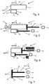
- FIG 1 to 7 A preferred embodiment of an extrusion system 1 according to the invention is shown in FIG 1 to 7 shown, wherein in 1 and 2 a pressing device 10 of the pressing system 1 and in Fig. 2 a cartridge device 40 of the extrusion system 1 is shown.
- the pressing-out device 10 is designed for pressing out multicomponent masses, the masses being able to be provided, for example, for filling, gluing or sealing or similar applications in the construction sector.
- the squeezing device 10 is for interaction with an in Fig. 3 shown cartridge device 40, which has two containers designed as cartridges 41 and 42.
- the cartridge device 40 can be arranged in a receiving space 11 of a housing 12 of the extrusion device 10 and can contain, for example, a two-component mortar composition.
- a curable resin component can be arranged in a chamber or cartridge 41 of the cartridge device 40 and a hardener component can be arranged in the further chamber or cartridge 42 of the cartridge device 40, which is arranged separately from the latter to inhibit the reaction.
- the mass formed after mixing the hardenable resin component and the hardener component is used, for example, as injection mortar for the chemical anchoring of, for example, metal elements in mineral substrates, such as, in particular, structures made of brickwork, concrete or natural stone.
- injection mortar for the chemical anchoring of, for example, metal elements in mineral substrates, such as, in particular, structures made of brickwork, concrete or natural stone.
- the boreholes required for fastening the anchoring means are made in the mineral substrate, after which the hardenable resin component is mixed with the hardening component of the two-component mortar composition and introduced into the borehole, whereupon the anchoring agent to be fastened is inserted and adjusted and the mortar composition then hardens.
- the housing 12 of the pressing device 10 extends essentially along an axial direction A and has a functional section 14 and a handling section 16.
- the functional section 14 essentially has the receiving space 11 and a machining head 19 on a distal end 18 of the functional section 14 on the machining side, into which a squeeze opening of the cartridges 41, 42, not shown, extends. Masses dispensed from the cartridges 41, 42 are mixed in particular in a mixing area 49 of the cartridge device 40 and are dispensed at the processing-side distal end 18 of the functional section 14 to a location to be processed.
- the handling section 16 of the housing 12 has, in addition to a handle 21, an actuating switch 22 which is arranged in the region of the handle 21 and which can be embodied, for example, as a so-called MOSFET switch.
- a pressing-out device 24 is provided for pressing out the cartridges 41, 42, which in the present case has two pressing-out pistons 25, 26, which in the present case are each firmly connected to a push rod 29A or 29B.
- Each ejection piston 25, 26 has a punch 27 or 28 at its end facing the respective cartridge 41 or 42.
- the electric motor 30 for displacing the squeezing piston 25 by means of the push rod 29A in the axial direction A and the electric motor 32 for displacing the squeezing piston 26 by means of the push rod 29B in the axial direction A.
- the squeeze pistons 25, 26 can be individually controlled in the direction of the distal via the push rods 29A and 29B which can be driven in a feed direction V by the electric motors 30, 32 End 18 movable.
- the electric motors 30 and 32 are supplied with energy by an energy supply designed as an accumulator 31.
- the squeezing device 10 can also be network-operated, it being possible to provide a plug which can be coupled to a power network.
- the squeezing device 10 furthermore has a control device 33, which is designed to actuate the electric motors 30 and 32 according to a user request by means of the actuation switch 22.
- the electric motors 30, 32 can be put into different operating modes by the control device 33, a deactivation mode being provided in which no current is fed from the accumulator 31 to the electric motors 30, 32 and actuation of the actuation switch 22 does not result in a displacement of the push rods 29A and 29B leads.
- the electric motors 30, 32 can also be put into an operating mode in which an actuation of the actuation switch 22 by the user leads to a displacement of the squeeze-out pistons 25 and 26 in the feed direction V at a respectively adapted speed.
- the cartridges 41, 42 of the cartridge device 40 each have an essentially cylindrical base body 43 or 44 with a first end wall 45 or 46 and an opposite second end wall 47 or 48.
- a dispensing opening is provided on the first end wall 45 and 46, respectively, which are connected to one another via the mixing region 49.
- an output device in the form of a spout can be connected to the mixing area 49.
- the second end wall 47 or 48 is designed to cooperate with the plunger 27 or 28 of the respective ejection piston 25 or 26, with a volume when the ejection piston 25 or 26 is displaced in the feed direction V in the direction of the first end wall 45 or 46 of the base body 43 or 44 of the respective cartridge 41 or 42 is reduced, so that the respective mass in the cartridges 41 and 42 is carried out through the dispensing opening, is mixed with one another in the mixing region 49 and is pressed out via the dispensing device.
- the squeezing system 1 also has a transmission device 60 which has at least one sensor 61 arranged on the squeezing device 10 and a signal transmitter 62 arranged on the cartridge device 40.
- the transmission device 60 is designed wirelessly and can operate using a variety of transmission principles. In particular, it is an RFID transmission device, but it can alternatively also be, for example, a Bluetooth transmission device, an NFC transmission device, a WiFi transmission device, a QR transmission device, a DMC transmission device, a WLAN transmission device, a ZigBee transmission device, a Wibree transmission device, a WiMAX transmission device, an IrDA transmission device or a transmission device operating according to optical directional radio.
- the signal transmitter 62 is arranged on an end face 50 of the mixing region 49 of the cartridge device 40
- the sensor 61 is arranged on the housing 12 of the dispenser 10 in such a way that the signal transmitter 62 of the cartridge device 40 with the cartridge device 40 arranged in the receiving space 11 in a prescribed manner interacts with the sensor 61 and signals can be transmitted from the signal generator 62 to the sensor 61.
- the sensor 61 is arranged, for example, in the region of a wall of the housing 12 which delimits a distal end region of the receiving region 11.
- the sensor 61 is coupled to the control device 33 by means of a further transmission device 65, it being possible for the further transmission device 65 to be implemented wirelessly or by wire.
- the further transmission device 65 can be designed on the basis of the same transmission mechanisms as the transmission device 60.
- the cartridges 41 and 42 of the cartridge device 40 according to Fig. 2 each have an essentially identical length in the axial direction A.
- a desired mixing ratio between the masses in the cartridges 41 and 42 is achieved here by actuating the squeezing pistons 25 and 26 by the respective electric motor 30 or 32 at an essentially identical speed.
- the cartridges 41 and 42 of the cartridge device 40 according to 4 to 7 have a different length in the axial direction A, the first cartridge 41 according to FIG Fig. 4 in the present case in the axial direction A is longer than the second cartridge 42.
- the first cartridge 41 is, for example, three times as long as the second cartridge 42 in the axial direction A.
- the first cartridge 41 is to be actuated in the present case at a feed rate of the first ejection piston 25 that is three times as high as the ejection piston 26 of the second cartridge 42.
- Fig. 5 are the ejection pistons 25, 26 each moved into a starting position, the plunger 27 of the first ejection plunger 25 essentially in contact with the first cartridge 41 of the cartridge device 40 and the plunger 28 of the second ejection piston 26 essentially in contact with the second cartridge 42 of the Cartridge device 40 is.
- Fig. 6 shows schematically a state of the ejection system 1 during an application-side actuation of the actuation switch 22, in which the ejection piston 25 acts on the first cartridge 41 at a feed rate that is three times the feed rate at which the ejection piston 26 acts on the second cartridge 42.
- the ratio of the feed speeds of the squeezing pistons 25 and 26 corresponds to a ratio of the lengths of the cartridges 41 and 42.
- Fig. 7 shows the squeezing pistons 25 and 26 in each case in a completely extended position, in which both the first cartridge 41 and the second cartridge 42 are essentially completely squeezed out.
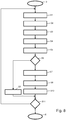
- FIG. 8 An embodiment of a method according to the invention for operating the squeezing system 1 is shown, the actuation of the squeezing pistons 25 and 26 being particularly adjustable by means of the method using the cartridge device 40 currently used. In this case, an incorrect setting with possible damage to both the dispensing device 10 and the cartridge device 40 can be reliably prevented.
- step S1 the cartridge device 40 is inserted into the receiving space 11.
- step S2 the signal transmitter 62 sends the cartridge device 40 a first signal, which specifies the cartridge device 40 in particular with regard to the length of the individual cartridges 41 and 42.
- the cartridge device 40 also additionally sends out a third signal and a fourth signal, the third signal specifying a starting position of the respective squeezing pistons 25 and 26.
- the fourth signal includes, for example, a date of expiration of the cartridge device 40, a permissible temperature range in the surrounding area for processing, or the like.
- the signals emitted by the cartridge device 40 are received by the sensor 61 of the extrusion device 10 in step S3 with the cartridge device 40 arranged in the receiving space 11 in a prescribed manner.
- step S4 the first signal, the third signal and the fourth signal are generated or generated from the first signal, the third signal and the fourth signal second signals sent from the sensor 61 to the control device 33.
- step S5 a ratio of feed speeds for the squeezing pistons 25 and 26 transmitted in the first signal is stored in a memory device 34 of the control device 33.
- the starting positions for the squeezing pistons 25 and 26 transmitted with the third signal are stored in the storage device 34.
- the second signal correlating with the fourth signal is compared, for example, with a current ambient temperature determined by a temperature sensor and, in the event that the current ambient temperature is within a permissible temperature range for the cartridge device 40, continue with step S7.
- it can be compared in query step S5 whether the current date lies before the permissible expiration date of the cartridge device 40. If the result is positive, continue with query step S7.
- step S6 If the query result in query step S6 is negative, the electric motors 30 and 32 are put into the deactivation mode by the control device 33 in step S8, so that actuation of the actuation switch 22 does not lead to a displacement of the push rods 29A and 29B and thus of the squeeze-out pistons 25 and 26.
- step S8 the control device 33 controls the electric motors 30, 32 in such a way that they are moved into the starting positions stored in the storage device 34, in which the punches 27 and 28 each essentially on the respective cartridge 41 and 42 concerns. Then, in step S9, the electric motors 30 and 32 are each transferred from the control device 33 into the operating mode. Subsequent actuation of the actuation switch 22 by the user leads in step S10 to the displacement of the squeeze-out pistons 25, 26 by the electric motors 30, 32.
- step S11 a query is made as to whether relevant framework conditions to be defined have changed to a predetermined extent. If the result of the query is positive, the method continues at step S1. If the query result is negative, the method is ended in step E.
- the cartridge device 40 used in each case is squeezed by the squeezing device 10 to the intended extent at the intended feed speeds of the squeezing pistons 25 and 26 and a desired mixing ratio of the cartridges 41 and 42 located in the cartridges Masses is achieved. Furthermore, damage to both the squeezing device 10 and the cartridge device 40 is prevented, which in conventional squeezing systems is caused, for example, by an incorrect setting of a Ratio of feed speeds of ejection pistons could occur.
- the transmission of corresponding data from the cartridge device 40 to the squeezing device 10 can easily prevent the cartridge device 40 from being used under definable impermissible general conditions which can lead to undesired processing results. It can also be prevented that damage to the cartridge device 40 and / or the squeezing device 10 occurs as a result of a cartridge device 40 incorrectly arranged in the receiving space if the signal transmitter 62 and the sensor 61 are designed and arranged such that a signal transmission between the signal transmitter 62 and the sensor 61 only takes place when the cartridge device 40 is arranged in the receiving space 11 to a prescribed extent.
- the squeezing device 10 has, in particular, an output device 70, which is designed, for example, to output a warning signal in an optical, acoustic and / or haptic manner when the electric motors 30 and 32 are transferred to the operating mode by the control device 33 in step S9.
- the control device 33 can also have a further memory device 72, which is designed to at least temporarily store the first signal, the second signal, the third signal and / or the fourth signal, and which can be read out via an output device. In this way, usage information of the pressing system 1 can be evaluated in a simple manner.
Landscapes
- Engineering & Computer Science (AREA)
- Mechanical Engineering (AREA)
- Computer Networks & Wireless Communication (AREA)
- Signal Processing (AREA)
- Coating Apparatus (AREA)
- Application Of Or Painting With Fluid Materials (AREA)
Abstract
Es wird ein Verfahren zum Betreiben eines Auspresssystems beschrieben, wobei die Kartuscheneinrichtung mit wenigstens zwei Kartuschen ausgebildet ist. Es ist eine Auspresseinrichtung mit wenigstens zwei mit unterschiedlichen Vorschubgeschwindigkeiten betreibbaren Auspresskolben vorgesehen. Das Verfahren umfasst folgende Schritte:- Hinterlegen eines Verhältnisses von Vorschubgeschwindigkeiten der Auspresskolben in einer Speichereinrichtung der Steuerungseinrichtung in Abhängigkeit des zweiten Signals (S5);- Ansteuerung der wenigstens einen Antriebseinrichtung von der Steuerungseinrichtung zur Verlagerung der beiden Auspresskolben in eine Startposition, in der ein Stempel des ersten Auspresskolbens im Wesentlichen in Anlage mit der ersten Kartusche der Kartuscheneinrichtung und in der ein Stempel des zweiten Auspresskolbens im Wesentlichen in Anlage mit der zweiten Kartusche der Kartuscheneinrichtung ist (S7)- Ansteuerung der wenigstens einen Antriebseinrichtung von der Steuerungseinrichtung mit einem in der Speichereinrichtung der Steuerungseinrichtung hinterlegten Verhältnis aus Vorschubgeschwindigkeiten für die Auspresskolben bei anwenderseitiger Anforderung (S10).Es wird weiterhin ein Auspresssystem zum Betreiben eines derartigen Verfahrens beschrieben.A method for operating a squeezing system is described, the cartridge device being designed with at least two cartridges. A squeezing device with at least two squeezing pistons that can be operated at different feed speeds is provided. The method comprises the following steps: - depositing a ratio of the feed speeds of the squeeze-out pistons in a memory device of the control device as a function of the second signal (S5); of the first squeezing piston essentially in contact with the first cartridge of the cartridge device and in which a plunger of the second squeezing piston is essentially in contact with the second cartridge of the cartridge device (S7) - control of the at least one drive device by the control device with one in the memory device of the Control device stored ratio of feed speeds for the squeezing pistons when requested by the user (S10). A squeezing system for operating such a method is also described.
Description
Die Erfindung betrifft ein Verfahren zum Betreiben eines ein Auspressgerät und eine Kartuscheneinrichtung umfassenden Auspresssystems gemäß dem Oberbegriff des Patentanspruches 1. Weiterhin betrifft die Erfindung ein Auspresssystem zur Durchführung eines derartigen Verfahrens gemäß dem Gegenstand des Patentanspruches 7.The invention relates to a method for operating a squeezing system comprising a squeezing device and a cartridge device according to the preamble of
Auspressgeräte werden beispielsweise im Baubereich zum Auspressen von Silikon oder anderen flüssigen bzw. zähflüssigen Baustoffen aus Kartuscheneinrichtungen verwendet. Dabei sind auch Auspressgeräte bekannt, die zum Aufnehmen von Kartuscheneinrichtungen ausgeführt sind, die zwei Kammern aufweisen. Derartige Kartuscheneinrichtungen können dabei beispielsweise eine Zwei- oder Mehrkomponenten-Mörtelmasse beinhalten, wobei in einer Kammer bzw. Kartusche der Kartuscheneinrichtung eine härtbare Harzkomponente und in einer weiteren davon reaktionsinhibierend getrennt angeordneten Kammer bzw. Kartusche der Kartuscheneinrichtung eine Härterkomponente angeordnet ist. Kartuscheneinrichtungen mit derartigen Zweikomponenten-Mörtelmassen werden beispielsweise als Injektionsmörtel für die chemische Verankerung beispielsweise von Metallelementen in mineralischen Untergründen, wie insbesondere Bauwerken aus Ziegelwerk, Beton oder Naturstein, eingesetzt. Dabei werden zunächst die entsprechend an die zur Befestigung der Verankerungsmittel erforderlichen Bohrlöcher in den mineralischen Untergrund eingebracht, wonach die härtbare Harzkomponente mit der Härterkomponente der Zweikomponenten-Mörtelmasse vermischt und in das Bohrloch eingebracht wird, worauf das zu befestigende Verankerungsmittel eingeführt und justiert wird, wonach die Mörtelmasse aushärtet.Squeezing devices are used, for example, in the construction sector for squeezing silicone or other liquid or viscous building materials from cartridge devices. In this case, squeezing devices are also known which are designed to hold cartridge devices which have two chambers. Cartridge devices of this type can contain, for example, a two- or multi-component mortar compound, a hardenable resin component being arranged in one chamber or cartridge of the cartridge device and a hardener component being arranged in another chamber or cartridge of the cartridge device which is arranged separately from the reaction inhibitor. Cartridge devices with such two-component mortar compositions are used, for example, as injection mortars for chemical anchoring, for example of metal elements in mineral substrates, such as, in particular, structures made of brickwork, concrete or natural stone. First of all, the drill holes required for fastening the anchoring means are made in the mineral subsurface, after which the hardenable resin component is mixed with the hardening component of the two-component mortar compound and introduced into the borehole, whereupon the anchoring agent to be fastened is inserted and adjusted, after which the Mortar hardens.
Der typische Aufbau eines solchen Auspressgeräts sieht an einer Schubstange angeordnete Auspresskolben vor, die jeweils einen Stempel in einer Vorschubrichtung in Richtung der Ausgabeöffnung der jeweiligen Kartusche bzw. Kammer der Kartuscheneinrichtung bewegen können. Der jeweilige Stempel wirkt dabei mit jeweils einer Kartusche zusammen und presst den Inhalt der jeweiligen Kartusche in Richtung der Ausgabeöffnung. Die Schubstange wird über einen gemeinsamen Antriebsmechanismus angetrieben.The typical structure of such an ejection device provides ejection pistons arranged on a push rod, each of which can move a plunger in a feed direction in the direction of the discharge opening of the respective cartridge or chamber of the cartridge device. The respective stamp cooperates with a cartridge and presses the contents of the respective cartridge in the direction of the dispensing opening. The push rod is driven by a common drive mechanism.
Für verschiedene Rezepturen von Zweikomponenten-Mörtelmassen sind verschiedene Mischverhältnisse der Komponenten in den einzelnen Kartuschen der Kartuscheneinrichtung erforderlich. Üblicherweise wird dies durch das Auspressen von Kartuschen mit identischer Antriebsgeschwindigkeit und unterschiedlichen Durchmessern erreicht.Different mixing ratios of the components in the individual cartridges of the cartridge device are required for different formulations of two-component mortar compositions. This is usually achieved by pressing cartridges with an identical drive speed and different diameters.
Um einen fehlerfreien Betrieb zu gewährleisten, ist es erforderlich, dass die jeweils verwendete Kartuscheneinrichtung auf das Auspressgerät abgestimmt ist und das Auspressgerät in einem auf die verwendete Kartuscheneinrichtung abgestimmten Betriebsmodus betrieben wird. Bei Verwendung von nicht aufeinander abgestimmten Kombinationen aus Kartuscheneinrichtung und Auspressgerät kann es einerseits zur Beschädigung der Kartuscheneinrichtung oder zur Beschädigung des Auspressgeräts kommen oder andererseits ein für die aktuell verwendete Kartuscheneinrichtung unerwünschtes Mischungsverhältnis zwischen den in den Kartuschen befindlichen Komponenten kommen.In order to ensure error-free operation, it is necessary for the cartridge device used in each case to be matched to the squeezing device and for the squeezing device to be operated in an operating mode matched to the cartridge device used. When using combinations of cartridge device and squeezing device that are not coordinated with one another, damage to the cartridge device or damage to the squeezing device can occur on the one hand or, on the other hand, an undesirable mixing ratio between the components located in the cartridges can occur for the currently used cartridge device.
Es ist Aufgabe der Erfindung ein Verfahren zum Betreiben eines Auspresssystems, das mit unterschiedlichen Vorschubgeschwindigkeiten von Auspresskolben betreibbar ist, und ein Auspresssystem zur Durchführung eines derartigen Verfahrens bereitzustellen, mit denen auf einfache und sichere Weise eine Beschädigung der eingesetzten Kartuscheneinrichtung und/oder des verwendeten Auspressgeräts zuverlässig verhinderbar ist und ein gewünschtes Mischungsverhältnis zwischen in den Kartuschen befindlichen Komponenten auf einfache Weise erzielbar ist.It is an object of the invention to provide a method for operating a squeezing system that can be operated by squeezing pistons at different feed speeds, and to provide a squeezing system for carrying out such a method with which damage to the cartridge device and / or the squeezing device used can be reliably and easily performed can be prevented and a desired mixing ratio between components located in the cartridges can be achieved in a simple manner.
Diese Aufgabe wird mit einem Verfahren zum Betreiben eines ein Auspressgerät und eine Kartuscheneinrichtung umfassenden Auspresssystems gelöst. Die Kartuscheneinrichtung ist mit wenigstens zwei Kartuschen bzw. zwei separaten Kammern ausgebildet und das Auspressgerät ist ausgeführt mit einem Aufnahmeraum zur Aufnahme der Kartuscheneinrichtung, einer Auspresseinrichtung mit wenigstens zwei mit unterschiedlichen Vorschubgeschwindigkeiten betreibbaren Auspresskolben, von denen jeder Auspresskolben zum Zusammenwirken mit einer Kartusche ausgeführt ist, einer Steuerungseinrichtung, wenigstens einer Antriebseinrichtung und einer Energieversorgung. Die Aufgabe wird dadurch gelöst, dass das Verfahren folgende Schritte umfasst:
- Einführen der Kartuscheneinrichtung in den Aufnahmeraum;
- Aussenden wenigstens eines ersten Signals von einem Signalgeber der Kartuscheneinrichtung;
- Empfangen des wenigstens einen Signals der Kartuscheneinrichtung mittels wenigstens eines Sensors des Auspressgeräts;
- Senden eines zweiten Signals von dem Sensor an die Steuerungseinrichtung;
- Hinterlegen eines Verhältnisses von Vorschubgeschwindigkeiten der Auspresskolben in einer Speichereinrichtung der Steuerungseinrichtung in Abhängigkeit von dem zweiten Signal;
- Ansteuerung der wenigstens einen Antriebseinrichtung von der Steuerungseinrichtung zur Verlagerung der beiden Auspresskolben in eine Startposition, in der ein Stempel des ersten Auspresskolbens im Wesentlichen in Anlage mit der ersten Kartusche der Kartuscheneinrichtung, und in der ein Stempel des zweiten Auspresskolbens im Wesentlichen in Anlage mit der zweiten Kartusche der Kartuscheneinrichtung ist; und
- Ansteuerung der wenigstens einen Antriebseinrichtung von der Steuerungseinrichtung mit einem in der Speichereinrichtung der Steuerungseinrichtung hinterlegten Verhältnis aus Vorschubgeschwindigkeiten für die Auspresskolben bei anwenderseitiger Anforderung.
- Inserting the cartridge device into the receiving space;
- Emitting at least a first signal from a signal generator of the cartridge device;
- Receiving the at least one signal of the cartridge device by means of at least one sensor of the squeezing device;
- Sending a second signal from the sensor to the controller;
- Depositing a ratio of feed speeds of the squeezing pistons in a storage device of the control device as a function of the second signal;
- Activation of the at least one drive device from the control device for displacing the two squeezing pistons into a starting position in which a plunger of the first squeezing piston essentially contacts the first cartridge of the cartridge device, and in which a plunger of the second squeezing piston is essentially in contact with the second cartridge of the cartridge device; and
- Control of the at least one drive device by the control device with a ratio of feed speeds for the squeezing pistons stored in the memory device of the control device when requested by the user.
Mit dem erfindungsgemäßen Verfahren ist auf einfache Weise sicherstellbar, dass bei einer anwenderseitigen Anforderung bzw. einer Betätigung eines hierfür vorgesehenen Schalters an dem Auspressgerät die Auspresskolben mit einem auf die verwendete Kartuscheneinrichtung abgestimmten Verhältnis aus Vorschubgeschwindigkeiten für die Auspresskolben betrieben wird und hierdurch ein gewünschtes Mischverhältnis zwischen den in den Kartuschen befindlichen Massen erzielt wird. Weiterhin ist mit dem erfindungsgemäßen Verfahren die Gefahr einer Beschädigung der Kartuscheneinrichtung und/oder des Auspressgeräts sicher verhindert, da mit dem erfindungsgemäßen Verfahren sichergestellt ist, dass die Positionierung der Auspresskolben in der Startposition und die Betätigung der Auspresskolben bei anwenderseitiger Anforderung auf die jeweils verwendete Kartuscheneinrichtung abgestimmt ist. Weiterhin können die Auswirkungen nutzerseitiges Fehlverhalten auf die Funktionsfähigkeit der Kartuscheneinrichtung und/oder des Auspressgeräts reduziert oder unterbunden werden. Zudem kann auf einfache Weise erkannt werden, ob ein kompatibles Auspresssystem vorliegt, d. h., ob die Kartuscheneinrichtung zur Verwendung in dem Auspressgerät geeignet ist. Auch dies reduziert die Gefahr einer Beschädigung der eingesetzten Kartuscheneinrichtung und/oder des Auspressgeräts.With the method according to the invention, it can be ensured in a simple manner that when a user requests or actuates a switch on the dispenser provided for this purpose, the dispensing pistons are operated with a ratio of feed speeds for the dispensing pistons that is matched to the cartridge device used, and thereby a desired mixing ratio between the dispensing pistons masses in the cartridges is achieved. Furthermore, the method according to the invention reliably prevents the risk of damage to the cartridge device and / or the squeezing device, since the method according to the invention ensures that the positioning of the squeeze-out pistons in the starting position and the actuation of the squeeze-out pistons are matched to the cartridge device used in each case when requested by the user is. Furthermore, the effects of user-side misconduct on the functionality of the cartridge device and / or the squeezing device can be reduced or prevented. In addition, it can be recognized in a simple manner whether a compatible squeezing system is present, i. i.e. whether the cartridge device is suitable for use in the squeezing device. This also reduces the risk of damage to the cartridge device and / or the squeezing device used.
Mit dem vorgeschlagenen Verfahren können verschiedene Mischverhältnisse der Komponenten in den einzelnen Kartuschen der Kartuscheneinrichtung durch unterschiedlichen Antriebsgeschwindigkeiten der zwei oder mehr Vorschubstangen realisiert werden. Hierdurch sind auch bei der Verwendung von identischen Kartuscheneinrichtungen, verschiedene Mischverhältbnisse von in den Kartuschen bzw. Kammern enthaltenen Komponenten erzielbar. Hierdurch werden sowohl die Kosten der Kartuscheneinrichtungen reduziert als auch die Anwendung vereinfacht.With the proposed method, different mixing ratios of the components in the individual cartridges of the cartridge device can be achieved by different drive speeds of the two or more feed rods. As a result, different mixing ratios of components contained in the cartridges or chambers can also be achieved when using identical cartridge devices. As a result, both the costs of the cartridge devices are reduced and the application is simplified.
Mittels des erfindungsgemäßen Verfahrens kann ein gewünschtes Mischverhältnis von sich in den Kartuschen bzw. Kammern der Kartuscheneinrichtung befindlichen Materialien auf einfache Weise eingestellt werden. Das erzielte Mischverhältnis ergibt sich in Abhängigkeit von Querschnitten, insbesondere Durchmessern der jeweiligen Kartuschen bzw. Kammern in Zusammenhang mit einem Verhältnis der jeweiligen Vorschubgeschwindigkeiten der Auspresskolben. Die Kartuschen können dabei einen voneinander abweichenden Querschnitt, insbesondere einen voneinander abweichenden Durchmesser aufweisen. Insbesondere kann es vorgesehen sein, dass die Kartuschen ein Längenverhältnis in Vorschubrichtung der Auspresskolben aufweisen, das im Wesentlichen dem Verhältnis der Vorschubgeschwindigkeiten der Auspresskolben entspricht. Hierdurch wird erreicht, dass beide Kartuschen im Wesentlichen gleichzeitig leer sind.Using the method according to the invention, a desired mixing ratio of materials located in the cartridges or chambers of the cartridge device can be set in a simple manner. The mixing ratio obtained is a function of cross sections, in particular diameters of the respective cartridges or chambers in connection with a ratio of the respective feed speeds of the squeezing pistons. The cartridges can have a different cross section, in particular a different diameter. In particular, it can be provided that the cartridges have an aspect ratio in the feed direction Have squeezing pistons, which essentially corresponds to the ratio of the feed speeds of the squeezing pistons. This ensures that both cartridges are essentially empty at the same time.
Zur Erzielung von voneinander abweichenden Mischverhältnissen der Komponenten in den Kartuschen einer Kartuscheneinrichtung sind verschiedene Bauarten von Kartuscheneinrichtungen in den Aufnahmeraum des Auspressgeräts einsetzbar. In den Aufnahmeraum des Auspressgeräts einsetzbare Kartuscheneinrichtungen weisen jeweils wenigstens zwei Kartuschen auf, die von denen eine Kartusche jeweils einen ersten Querschnitt und eine weitere Kartusche einen zweiten Querschnitt aufweisen. Verschiedene Kartuscheneinrichtungen unterscheiden sich insbesondere lediglich hinsichtlich der Länge der einzelnen Kartuschen in Vorschubrichtung der Auspresskolben. Durch eine entsprechende Wahl von Längenverhältnissen der Kartuschen ist auf einfache Weise bei einem gewünschten Mischverhältnis erzielbar, dass beide Kartuschen im Wesentlichen gleichzeitig aufgebraucht sind.To achieve different mixing ratios of the components in the cartridges of a cartridge device, different types of cartridge devices can be used in the receiving space of the dispenser. Cartridge devices that can be used in the receiving space of the dispenser each have at least two cartridges, one of which has a first cross-section and another has a second cross-section. Different cartridge devices differ in particular only with regard to the length of the individual cartridges in the feed direction of the squeezing pistons. With a corresponding choice of aspect ratios of the cartridges, it can be easily achieved with a desired mixing ratio that both cartridges are used up essentially simultaneously.
Wenn eine Kartusche sämtlicher eingesetzter Kartuscheneinrichtungen eine feste Länge in Vorschubrichtung des Auspresskolbens aufweist, kann bei einer vorteilhaften Ausführungsform des erfindungsgemäßen Verfahrens die Steuerungseinrichtung auf einfache Weise die Startposition der jeweiligen Auspresskolben aus dem in der Speichereinrichtung hinterlegten Verhältnis von Vorschubgeschwindigkeiten der Auspresskolben ermitteln.If a cartridge of all of the cartridge devices used has a fixed length in the feed direction of the ejection piston, in an advantageous embodiment of the method according to the invention the control device can easily determine the starting position of the respective ejection piston from the ratio of feed speeds of the ejection piston stored in the storage device.
Eine vorteilhafte Ausführungsform ist durch das Aussenden wenigstens eines dritten Signals von dem Signalgeber der Kartuscheneinrichtung gekennzeichnet, welches eine Startposition der jeweiligen Auspresskolben in der Speichereinrichtung hinterlegt. Hierdurch können die Stempel der Auspresskolben durch eine entsprechende Ansteuerung der wenigstens einen Antriebseinrichtung automatisiert in die jeweilige Startposition gebracht werden.An advantageous embodiment is characterized by the transmission of at least a third signal from the signal transmitter of the cartridge device, which stores a starting position of the respective squeezing pistons in the storage device. As a result, the stamps of the squeeze-out pistons can be brought automatically into the respective starting position by appropriate control of the at least one drive device.
Es kann vorgesehen sein, dass von dem Signalgeber der Kartuscheneinrichtung wenigstens ein viertes Signal ausgesendet wird, welches die Antriebseinrichtung in einen Deaktivierungzustand einstellt, d. h., die Antriebseinrichtung in diesen Zustand versetzt wird oder in diesem verbleibt, wenn das vierte Signal einen in der Steuereinrichtung hinterlegten Schwellwert überschreitet oder außerhalb eines festgelegten Bereichs liegt. Hierdurch kann beispielsweise auf einfache Weise eine Verlagerung der Auspresskolben bei anwenderseitiger Anforderung verhindert werden, wenn ein Ablaufdatum der Kartuscheneinrichtung überschritten ist oder ein auf der Kartuscheneinrichtung hinterlegter zulässiger Temperaturbereich nicht vorliegt.It can be provided that the signal transmitter of the cartridge device emits at least a fourth signal, which sets the drive device into a deactivation state, i. that is, the drive device is placed in this state or remains in this state if the fourth signal exceeds a threshold value stored in the control device or lies outside a defined range. In this way, for example, displacement of the squeeze-out pistons can be prevented in a simple manner when the user requests it, if an expiry date of the cartridge device has been exceeded or an admissible temperature range stored on the cartridge device does not exist.
Bei einer bevorzugten Ausführungsform wird durch einen Warnsignalgeber ein Warnsignal ausgesendet, wenn das zweite Signal keinem in der Steuerungseinrichtung hinterlegten Wert entspricht. Dem Anwender kann hierdurch beispielsweise auf akustische, visuelle oder haptische Weise mitgeteilt werden, wenn eine nicht mit dem Auspressgerät kompatible Kartuscheneinrichtung vorliegt oder ein für die Kartuscheneinrichtung erforderliches Mischverhältnis von dem Auspressgerät nicht umsetzbar ist.In a preferred embodiment, a warning signal is emitted by a warning signal generator if the second signal does not correspond to a value stored in the control device. The user can hereby be informed acoustically, visually or haptically, for example, if a cartridge device that is not compatible with the extrusion device is present or a mixing ratio required for the cartridge device cannot be implemented by the dispenser.
Ein derartiges Warnsignal durch einen Warnsignalgeber kann auch oder zusätzlich hierzu ausgesendet werden, wenn die Antriebseinrichtung durch das vierte Signal in den Deaktivierungszustand eingestellt wird und/oder das vierte Signal einen in der Steuerungseinrichtung hinterlegten Schwellwert überschreitet.Such a warning signal by a warning signal generator can also or additionally be emitted if the drive device is set to the deactivation state by the fourth signal and / or the fourth signal exceeds a threshold value stored in the control device.
Es wird weiterhin ein Auspresssystem zur Durchführung eines derartigen Verfahrens vorgeschlagen, wobei das Auspresssystem mit einem Auspressgerät und einer Kartuscheneinrichtung ausgeführt ist, die mit wenigstens zwei Kartuschen ausgebildet ist und das Auspressgerät ausgeführt ist mit einem Aufnahmeraum zur Aufnahme der Kartuscheneinrichtung, einer Auspresseinrichtung mit wenigstens zwei mit unterschiedlichen Vorschubgeschwindigkeiten betreibbaren Auspresskolben, von denen jeder Auspresskolben zum Zusammenwirken mit einer Kartusche ausgebildet ist, einer Steuerungseinrichtung, wenigstens einer Antriebseinrichtung und einer Energieversorgung.A squeezing system for carrying out such a method is also proposed, the squeezing system being designed with a squeezing device and a cartridge device which is designed with at least two cartridges and the squeezing device being designed with a receiving space for receiving the cartridge device, a squeezing device with at least two Ejection pistons that can be operated at different feed speeds, of which each ejection piston is designed to interact with a cartridge, a control device, at least one drive device, and an energy supply.
Mit dem erfindungsgemäßen Auspresssystem ist auf einfache Weise sicherstellbar, dass bei einer anwenderseitigen Anforderung bzw. einer Betätigung eines hierfür vorgesehenen Betätigungsschalters an dem Auspressgerät durch einen Anwender die Auspresskolben mit einem auf die verwendete Kartuscheneinrichtung abgestimmten Verhältnis aus Vorschubgeschwindigkeiten für die Auspresskolben betrieben werden. Hierdurch ist die Gefahr einer Beschädigung der Kartuscheneinrichtung und/oder des Auspressgeräts sicher verhindert. Weiterhin können gegebenenfalls die Auswirkungen nutzerseitiges Fehlverhalten auf die Funktionsfähigkeit der Kartuscheneinrichtung und/oder des Auspressgeräts reduziert oder unterbunden werden. Zudem kann auf einfache Weise erkannt werden, ob ein kompatibles Auspresssystem vorliegt, d. h., ob die Kartuscheneinrichtung zur Verwendung in dem Auspressgerät geeignet ist. Auch dies reduziert die Gefahr einer Beschädigung der eingesetzten Kartuscheneinrichtung und/oder des Auspressgeräts.With the squeezing system according to the invention, it can be ensured in a simple manner that when a user requests or an actuation switch on the squeezing device is actuated by a user, the squeezing pistons are operated with a ratio of feed speeds for the squeezing pistons that is matched to the cartridge device used. This reliably prevents the risk of damage to the cartridge device and / or the dispenser. Furthermore, the effects of user-side misconduct on the functionality of the cartridge device and / or the squeezing device can be reduced or prevented. In addition, it can be easily recognized whether a compatible squeezing system is available, i.e. i.e. whether the cartridge device is suitable for use in the squeezing device. This also reduces the risk of damage to the cartridge device and / or the squeezing device used.
Um eine Signalübertragung zwischen der Kartuscheneinrichtung und dem Auspressgerät auf konstruktiv einfache Weise umzusetzen, kann eine drahtlose Übertragungseinrichtung mit einem der Kartuscheneinrichtung zugeordneten Signalgeber und wenigstens einem dem Auspressgerät zugeordneten Sensor vorgesehen sein. Mittels der Übertragungseinrichtung ist eine Signalübertragung von der Kartuscheneinrichtung auf das Auspressgerät möglich und ein Auspressvorgang hierdurch hinsichtlich der jeweils verwendeten Kartuscheneinrichtung optimierbar.In order to implement a signal transmission between the cartridge device and the squeezing device in a structurally simple manner, a wireless transmission device can be provided with a signal transmitter assigned to the cartridge device and at least one sensor assigned to the squeezing device. A signal transmission from the cartridge device to the squeezing device is possible by means of the transmission device and a squeezing process can thereby be optimized with regard to the cartridge device used in each case.
Bei einer bevorzugten Ausführung ist die drahtlose Übertragungseinrichtung eine optische Übertragungseinrichtung oder eine Funkübertragungseinrichtung. Die Übertragungseinrichtung kann dabei auf verschieden Funktionsprinzipien und/oder Standards basieren. Die Funktionsweise der Übertragungseinrichtung kann sowohl auf einer Signalübertragung im Radiofrequenzbereich beispielsweise mittels Ultrakurzwelle, Kurzwelle oder Mittelwelle als auch auf einer Signalübertragung im infraroten oder optischen Frequenzbereich basieren. Insbesondere ist die Übertragungseinrichtung als RFID-Übertragungseinrichtung, als Bluetooth-Übertragungseinrichtung, als NFC-Übertragungseinrichtung, als WiFi-Übertragungseinrichtung, als QR-Übertragungseinrichtung oder als DMC-Übertragungseinrichtung ausgeführt. Weiterhin kann die Übertragungseinrichtung als WLAN-Übertragungseinrichtung, als ZigBee-Übertragungseinrichtung, als Wibree-Übertragungseinrichtung, WiMAX-Übertragungseinrichtung, als IrDA-Übertragungseinrichtung oder als nach optischem Richtfunk arbeitende Übertragungseinrichtung ausgeführt sein.In a preferred embodiment, the wireless transmission device is an optical transmission device or a radio transmission device. The transmission device can be based on different functional principles and / or standards. The Operation of the transmission device can be based both on a signal transmission in the radio frequency range, for example by means of ultra-short wave, short wave or medium wave, and on a signal transmission in the infrared or optical frequency range. In particular, the transmission device is designed as an RFID transmission device, as a Bluetooth transmission device, as an NFC transmission device, as a WiFi transmission device, as a QR transmission device or as a DMC transmission device. Furthermore, the transmission device can be designed as a WLAN transmission device, as a ZigBee transmission device, as a Wibree transmission device, WiMAX transmission device, as an IrDA transmission device or as a transmission device operating according to optical directional radio.
Eine Übertragung des von der Kartuscheneinrichtung ausgesendeten und von dem wenigstens einen Sensor empfangenen Signals an die Steuerungseinrichtung wird bei einer einfach umzusetzenden Weiterbildung dadurch erreicht, dass eine weitere Übertragungseinrichtung zwischen dem wenigstens einen Sensor und der Steuerungseinrichtung vorgesehen ist, die drahtgebunden oder drahtlos ausgeführt ist.A transmission of the signal emitted by the cartridge device and received by the at least one sensor to the control device is achieved in a development that is easy to implement in that a further transmission device is provided between the at least one sensor and the control device, which is wired or wireless.
Die weitere Übertragungseinrichtung kann prinzipiell vergleichbar zur der Übertragungseinrichtung ausgeführt sein und beispielsweise als RFID-Übertragungseinrichtung, als Bluetooth-Übertragungseinrichtung, als NFC-Übertragungseinrichtung, als WiFi-Übertragungseinrichtung, als QR-Übertragungseinrichtung oder als DMC-Übertragungseinrichtung ausgeführt sein. Weiterhin kann die Übertragungseinrichtung als WLAN-Übertragungseinrichtung, als ZigBee-Übertragungseinrichtung, als Wibree-Übertragungseinrichtung, WiMAX-Übertragungseinrichtung, als IrDA-Übertragungseinrichtung oder als nach optischem Richtfunk arbeitende Übertragungseinrichtung ausgeführt sein.The further transmission device can in principle be designed to be comparable to the transmission device and can be designed, for example, as an RFID transmission device, as a Bluetooth transmission device, as an NFC transmission device, as a WiFi transmission device, as a QR transmission device or as a DMC transmission device. Furthermore, the transmission device can be designed as a WLAN transmission device, as a ZigBee transmission device, as a Wibree transmission device, WiMAX transmission device, as an IrDA transmission device or as a transmission device operating according to optical directional radio.
Um eine Interaktion mit einem Anwender auf konstruktiv einfache Weise erzielen zu können, ist bei einer vorteilhaften Ausführung eine Ausgabeeinrichtung an einem Gehäuse des Auspressgeräts vorgesehen. Die Ausgabeeinrichtung kann beispielsweise als Warneinrichtung ausgeführt sein, die zur Ausgabe von optischen, akustischen und/oder haptischen Signalen ausgeführt ist. Die Ausgabeeinrichtung kann hierbei beispielsweise eine an dem Auspressgerät angeordnete Anzeigeeinrichtung vorzugsweise in Form eines Displays umfassen. Alternativ oder zusätzlich hierzu kann es vorgesehen sein, dass die Ausgabeeinrichtung Teil einer Übertragungseinrichtung ist, die beispielsweise zur drahtlosen Verbindung mit einer separaten Anzeigeeinrichtung, beispielsweise einem Mobilfunkgerät bzw. einem Smartphone, ausgeführt ist.In order to be able to achieve an interaction with a user in a structurally simple manner, in an advantageous embodiment an output device is provided on a housing of the dispenser. The output device can be designed, for example, as a warning device that is designed to output optical, acoustic and / or haptic signals. The output device can, for example, comprise a display device arranged on the squeezing device, preferably in the form of a display. As an alternative or in addition to this, it can be provided that the output device is part of a transmission device which is designed, for example, for the wireless connection to a separate display device, for example a mobile radio device or a smartphone.
Bei einer vorteilhaften Ausführung weist das Auspressgerät wenigstens eine zum wenigstens temporären Speichern des ersten Signals, des zweiten Signals, des dritten Signals und/oder des vierten Signals ausgeführte auslesbare Speichereinrichtung auf. Die Speichereinrichtung ist vorzugsweise über eine Ausgabeeinrichtung auslesbar, so dass auf der Speichereinrichtung hinterlegte Daten auswertbar sind.In an advantageous embodiment, the squeezing device has at least one readable memory device designed for at least temporarily storing the first signal, the second signal, the third signal and / or the fourth signal. The storage device can preferably be read out via an output device, so that data stored on the storage device can be evaluated.
Um verschiedene Verhältnisse von Vorschubgeschwindigkeiten der beiden Auspresskolben auf einfache Weise erzielen zu können, ist bei einer konstruktiv einfachen Ausführung eine Getriebeeinrichtung vorgesehen, die zur Einstellung von verschiedenen Verhältnissen von Vorschubgeschwindigkeiten des ersten Auspresskolbens zu dem zweiten Auspresskolben ausgeführt ist, wobei die Auspresskolben von einer gemeinsamen Antriebseinrichtung betätigbar sind. Dadurch, dass die verschiedenen Verhältnisse von Vorschubgeschwindigkeiten mittels einer einzigen Antriebseinrichtung umsetzbar sind, ist hierbei ein kostengünstig umsetzbares Auspresssystem geschaffen.In order to be able to achieve different ratios of feed speeds of the two squeezing pistons in a simple manner, in a structurally simple embodiment a gear device is provided which is designed to set different ratios of feed rates of the first squeezing piston to the second squeezing piston, the squeezing pistons being provided by a common drive device can be operated. Because the different ratios of feed speeds can be implemented by means of a single drive device, a squeezing system that can be implemented cost-effectively is created.
Bei einer hierzu alternativen Ausführung sind zwei Antriebseinrichtungen vorgesehen, wobei eine erste Antriebseinrichtung zur Betätigung des ersten Auspresskolbens und eine zweite Antriebseinrichtung zur Betätigung des zweiten Auspresskolbens ausgeführt ist. Hierdurch ist eine besonders genaue und stufenlose Einstellung eines Verhältnisses von Vorschubgeschwindigkeiten zwischen dem ersten Auspresskolben und dem zweiten Auspresskolben erzielt.In an alternative embodiment, two drive devices are provided, a first drive device for actuating the first squeezing piston and a second drive device for actuating the second squeezing piston. This achieves a particularly precise and infinitely variable setting of a ratio of feed speeds between the first squeezing piston and the second squeezing piston.
Weitere Vorteile ergeben sich aus der folgenden Figurenbeschreibung. In den Figuren ist ein Ausführungsbeispiel der vorliegenden Erfindung dargestellt. Die Figuren, die Beschreibung und die Ansprüche enthalten zahlreiche Merkmale in Kombination. Der Fachmann wird die Merkmale zweckmäßigerweise auch einzeln betrachten und sinnvollen weiteren Kombinationen zusammenfassen.Further advantages result from the following description of the figures. An exemplary embodiment of the present invention is shown in the figures. The figures, the description and the claims contain numerous features in combination. The person skilled in the art will expediently also consider the features individually and summarize useful further combinations.
In den Figuren sind gleiche und gleichartige Komponenten mit gleichen Bezugszeichen beziffert.In the figures, the same and similar components are numbered with the same reference numerals.
Es zeigen:
- Fig. 1
- eine vereinfachte dreidimensionale Darstellung eines Auspressgerätes eines Auspresssystems;
- Fig. 2
- eine vereinfachte Seitenansicht des Auspressgerätes des Auspresssystems gemäß
Fig. 1 - Fig. 3
- eine dreidimensionale Darstellung einer zum Zusammenwirken mit dem Auspressgerät gemäß
Fig. 1 und Fig. 2 ausgeführten Kartuscheneinrichtung des Auspresssystems, wobei die Kartuscheneinrichtung mit zwei Kartuschen ausgeführt ist; - Fig. 4
- eine schematische Darstellung des Auspressgeräts gemäß
Fig. 1 und Fig. 2 mit in einem Aufnahmeraum des Auspressgeräts angeordneter Kartuscheneinrichtung; - Fig. 5
- eine
Fig. 4 entsprechende Ansicht des Auspresssystems, wobei die Auspresskolben der Auspresseinrichtung in eine Startposition verlagert sind; - Fig. 6
- eine
Fig. 4 und Fig. 5 entsprechende Ansicht des Auspresssystems, während einer anwenderseitigen Betätigung des Auspressgeräts; - Fig. 7
- eine
Fig. 4 bis Fig. 6 entsprechende Ansicht des Auspresssystems nach einer im Wesentlichen vollständigen Entleerung von Kartuschen der Kartuscheneinrichtung; und - Fig. 8
- eine vereinfachte Darstellung eines Ablaufdiagramms einer Ausführungsform eines erfindungsgemäßen Verfahrens zum Betreiben des Auspresssystems gemäß
Fig. 1 bis Fig. 7 .
- Fig. 1
- a simplified three-dimensional representation of a pressing device of a pressing system;
- Fig. 2
- a simplified side view of the pressing device of the pressing system according to
Fig. 1 - Fig. 3
- a three-dimensional representation of a to interact with the squeezer according to
1 and 2 executed cartridge device of the squeezing system, the cartridge device being designed with two cartridges; - Fig. 4
- a schematic representation of the squeezer according to
1 and 2 with a cartridge device arranged in a receiving space of the dispenser; - Fig. 5
- a
Fig. 4 corresponding view of the squeezing system, the squeezing pistons of the squeezing device being displaced into a starting position; - Fig. 6
- a
4 and 5 corresponding view of the squeezing system, during a user actuation of the squeezing device; - Fig. 7
- a
4 to 6 corresponding view of the squeezing system after substantially complete emptying of cartridges from the cartridge device; and - Fig. 8
- a simplified representation of a flow chart of an embodiment of a method according to the invention for operating the squeeze system according to
1 to 7 .
Ein bevorzugtes Ausführungsbeispiel eines erfindungsgemäßen Auspresssystems 1 ist in
Das Auspressgerät 10 ist vorliegend zur Auspressen von mehrkomponentigen Massen ausgeführt, wobei die Massen beispielsweise zum Verfüllen, Kleben oder Abdichten oder dergleichen Anwendungen im Baubereich vorgesehen sein können.In the present case, the pressing-out
Vorliegend ist das Auspressgerät 10 zum Zusammenwirken mit einer in
Das Gehäuse 12 des Auspressgeräts 10 erstreckt sich vorliegend im Wesentlichen entlang einer axialen Richtung A und hat einen Funktionsabschnitt 14 und einen Handhabungsabschnitt 16. Der Funktionsabschnitt 14 weist im Wesentlichen den Aufnahmeraum 11 und an einem bearbeitungsseitigen distalen Ende 18 des Funktionsabschnitts 14 einen Bearbeitungskopf 19 auf, in den hinein sich eine nicht näher dargestellte Auspressöffnung der Kartuschen 41, 42 erstreckt. Aus den Kartuschen 41, 42 abgegebene Massen werden insbesondere in einem Mischbereich 49 der Kartuscheneinrichtung 40 gemischt und am bearbeitungsseitigen distalen Ende 18 des Funktionsabschnitts 14 an eine zu bearbeitende Stelle abgegeben.In the present case, the
Der Handhabungsabschnitt 16 des Gehäuses 12 weist neben einem Haltegriff 21 einen im Bereich des Haltegriffs 21 angeordneten Betätigungsschalter 22 auf, der beispielsweise als sogenannter MOSFET-Schalter ausgeführt sein kann. Zum Auspressen der Kartuschen 41, 42 ist eine Auspresseinrichtung 24 vorgesehen, die vorliegend mit zwei Auspresskolben 25, 26 ausgeführt ist, die vorliegend jeweils mit einer Schubstange 29A bzw. 29B fest verbunden sind. Jeder Auspresskolben 25, 26 weist an seinem der jeweiligen Kartusche 41 bzw. 42 zugewandten Ende einen Stempel 27 bzw. 28 auf.The
Es sind weiterhin zwei insbesondere als Elektromotor 30 bzw. 32 ausgeführte und in
Die Elektromotoren 30 und 32 werden vorliegend von einer als Akkumulator 31 ausgeführten Energieversorgung mit Energie versorgt. Alternativ hierzu kann das Auspressgerät 10 auch netzbetrieben sein, wobei ein mit einem Stromnetz koppelbarer Stecker vorgesehen sein kann. Das Auspressgerät 10 weist weiterhin eine Steuerungseinrichtung 33 auf, welche zur Betätigung der Elektromotoren 30 und 32 nach einer anwenderseitigen Anforderung mittels des Betätigungsschalters 22 ausgeführt ist.In the present case, the
Die Elektromotoren 30, 32 können von der Steuerungseinrichtung 33 in verschiedene Betriebsmodi versetzt werden, wobei ein Deaktivierungsmodus vorgesehen ist, in dem kein Strom von dem Akkumulator 31 zu den Elektromotoren 30, 32 geführt wird und eine Betätigung des Betätigungsschalters 22 nicht zu einer Verlagerung der Schubstangen 29A und 29B führt. Die Elektromotoren 30, 32 sind weiterhin in einen Betriebsmodus versetzbar, in dem eine anwenderseitige Betätigung des Betätigungsschalters 22 zu einer Verlagerung der Auspresskolben 25 und 26 in Vorschubrichtung V mit einer jeweils angepassten Geschwindigkeit führt.The
Die Kartuschen 41, 42 der Kartuscheneinrichtung 40 weisen vorliegend jeweils einen im Wesentlichen zylindrischen Grundkörper 43 bzw. 44 mit einer ersten Stirnwand 45 bzw. 46 und einer gegenüberliegenden zweiten Stirnwand 47 bzw. 48 auf. An der ersten Stirnwand 45 bzw. 46 ist jeweils eine Ausgabeöffnung vorgesehen, die über den Mischbereich 49 miteinander verbunden sind. An den Mischbereich 49 ist beispielsweise eine Ausgabeeinrichtung in Form einer Tülle anbindbar. Die zweite Stirnwand 47 bzw. 48 ist zum Zusammenwirken mit dem Stempel 27 bzw. 28 des jeweiligen Auspresskolbens 25 bzw. 26 ausgeführt, wobei bei einer Verlagerung des Auspresskolbens 25 bzw. 26 in Vorschubrichtung V in Richtung der ersten Stirnwand 45 bzw. 46 ein Volumen des Grundkörpers 43 bzw. 44 der jeweiligen Kartusche 41 bzw. 42 verringert wird, sodass die jeweilige Masse in den Kartuschen 41 und 42 durch die Ausgabeöffnung ausgeführt, in dem Mischbereich 49 miteinander vermischt und über die Ausgabeeinrichtung herausgepresst wird.The
Das Auspresssystem 1 weist weiterhin eine Übertragungseinrichtung 60 auf, die wenigstens einen an dem Auspressgerät 10 angeordneten Sensor 61 und einen an der Kartuscheneinrichtung 40 angeordneten Signalgeber 62 aufweist. Die Übertragungseinrichtung 60 ist drahtlos ausgeführt und kann mittels vielfältiger Übertragungsprinzipien arbeiten. Insbesondere handelt es sich um eine RFID-Übertragungseinrichtung, allerdings kann es sich alternativ hierzu beispielsweise auch um eine Bluetooth-Übertragungseinrichtung, eine NFC-Übertragungseinrichtung, eine WiFi-Übertragungseinrichtung, eine QR-Übertragungseinrichtung, eine DMC-Übertragungseinrichtung, eine WLAN-Übertragungseinrichtung, eine ZigBee-Übertragungseinrichtung, eine Wibree-Übertragungseinrichtung, eine WiMAX-Übertragungseinrichtung, eine IrDA-Übertragungseinrichtung oder eine nach optischem Richtfunk arbeitende Übertragungseinrichtung handeln.The squeezing
Der Signalgeber 62 ist vorliegend an einer Stirnseite 50 des Mischbereichs 49 der Kartuscheneinrichtung 40 angeordnet, wohingegen der Sensor 61 derart an dem Gehäuse 12 des Auspressgeräts 10 angeordnet ist, dass der Signalgeber 62 der Kartuscheneinrichtung 40 bei in vorgeschriebener Weise in dem Aufnahmeraum 11 angeordneter Kartuscheneinrichtung 40 in Wechselwirkung mit dem Sensor 61 tritt und Signale von dem Signalgeber 62 an den Sensor 61 übertragbar sind. Der Sensor 61 ist hierzu beispielsweise im Bereich einer einen distalen Endbereich des Aufnahmebereichs 11 begrenzenden Wand des Gehäuses 12 angeordnet.In the present case, the
Der Sensor 61 ist mittels einer weiteren Übertragungseinrichtung 65 mit der Steuerungseinrichtung 33 gekoppelt, wobei die weitere Übertragungseinrichtung 65 drahtlos oder drahtgebunden ausgeführt sein kann. Die weitere Übertragungseinrichtung 65 kann auf Basis der gleichen Übertragungsmechanismen wie die Übertragungseinrichtung 60 ausgeführt sein.The
Die Kartuschen 41 und 42 der Kartuscheneinrichtung 40 gemäß
Die Kartuschen 41 und 42 der Kartuscheneinrichtung 40 gemäß
In
In
Das Verfahren beginnt mit dem Start S. Im Schritt S1 wird die Kartuscheneinrichtung 40 in den Aufnahmeraum 11 eingelegt. In Schritt S2 sendet der Signalgeber 62 der Kartuscheneinrichtung 40 ein erstes Signal aus, welches die Kartuscheneinrichtung 40 insbesondere hinsichtlich der Länge der einzelnen Kartuschen 41 und 42 näher spezifiziert. Weiterhin sendet die Kartuscheneinrichtung 40 vorliegend zusätzlich ein drittes Signal und ein viertes Signal aus, wobei das dritte Signal eine Startposition der jeweiligen Auspresskolben 25 und 26 spezifiziert. Das vierte Signal beinhaltet beispielsweise ein Haltbarkeitsdatum der Kartuscheneinrichtung 40, einen zulässigen Temperaturbereich an Umgebungsbereich für die Verarbeitung oder dergleichen. Die von der Kartuscheneinrichtung 40 ausgesendeten Signale werden von dem Sensor 61 des Auspressgeräts 10 in Schritt S3 bei in vorgeschriebener Weise in dem Aufnahmeraum 11 angeordneter Kartuscheneinrichtung 40 empfangen.The method begins with the start S. In step S1, the
Daraufhin werden in Schritt S4 dem ersten Signal, dem dritten Signal und dem vierten Signal entsprechende bzw. aus dem ersten Signal, dem dritten Signal und dem vierten Signal generierte zweite Signale von dem Sensor 61 an die Steuerungseinrichtung 33 gesendet. Im darauffolgenden Schritt S5 wird ein in dem ersten Signal übermitteltes Verhältnis von Vorschubgeschwindigkeiten für die Auspresskolben 25 und 26 in einer Speichereinrichtung 34 der Steuerungseinrichtung 33 hinterlegt. Ebenso werden in der Speichereinrichtung 34 vorliegend die mit dem dritten Signal übermittelten Startpositionen für die Auspresskolben 25 und 26 hinterlegt.Then, in step S4, the first signal, the third signal and the fourth signal are generated or generated from the first signal, the third signal and the fourth signal second signals sent from the
Im Abfrageschritt S6 wird das mit dem vierten Signal korrelierende zweite Signal beispielsweise mit einer durch einen Temperatursensor ermittelten, aktuell vorliegenden Umgebungstemperatur verglichen und für den Fall, dass die aktuell vorliegende Umgebungstemperatur innerhalb eines zulässigen Temperaturbereichs für die Kartuscheneinrichtung 40 liegt, mit Schritt S7 fortgefahren. Alternativ oder zusätzlich hierzu kann im Abfrageschritt S5 verglichen werden, ob das aktuelle Datum vor dem zulässigen Haltbarkeitsdatum der Kartuscheneinrichtung 40 liegt. Bei positivem Ergebnis wird mit Abfrageschritt S7 fortgefahren.In query step S6, the second signal correlating with the fourth signal is compared, for example, with a current ambient temperature determined by a temperature sensor and, in the event that the current ambient temperature is within a permissible temperature range for the
Bei negativem Abfrageergebnis im Abfrageschritt S6 werden die Elektromotoren 30 und 32 von der Steuerungseinrichtung 33 in Schritt S8 in den Deaktivierungsmodus versetzt, so dass eine Betätigung des Betätigungsschalters 22 nicht zu einer Verlagerung der Schubstangen 29A und 29B und somit der Auspresskolben 25 und 26 führt.If the query result in query step S6 is negative, the
Nach positivem Abfrageergebnis im Abfrageschritt S6 steuert im Schritt S8 die Steuerungseinrichtung 33 die Elektromotoren 30, 32 derart an, dass diese in die in der Speichereinrichtung 34 hinterlegten Startpositionen verfahren werden, in denen die Stempel 27 und 28 jeweils im Wesentlichen an der jeweiligen Kartusche 41 und 42 anliegen. Anschließend werden die Elektromotoren 30 und 32 im Schritt S9 von der Steuerungseinrichtung 33 jeweils in den Betriebsmodus überführt. Eine anschließende anwenderseitige Betätigung des Betätigungsschalters 22 führt im Schritt S10 zur Verlagerung der Auspresskolben 25, 26 durch die Elektromotoren 30, 32.After a positive query result in query step S6, in step S8 the
Im an die Schritte S8 und S10 anschließenden Abfrageschritt S11 wird abgefragt, ob sich zu definierende relevante Rahmenbedingungen in vorgegebenem Umfang geändert haben. Bei positivem Abfrageergebnis wird das Verfahren bei Schritt S1 fortgesetzt. Bei negativem Abfrageergebnis wird das Verfahren bei Schritt E beendet.In the query step S11 following the steps S8 and S10, a query is made as to whether relevant framework conditions to be defined have changed to a predetermined extent. If the result of the query is positive, the method continues at step S1. If the query result is negative, the method is ended in step E.
Mittels des Verfahrens zum Betreiben des Auspresssystems 1 ist auf einfache Weise sicherstellbar, dass die jeweils verwendete Kartuscheneinrichtung 40 im vorgesehenen Umfang von dem Auspressgerät 10 mit den vorgesehenen Vorschubgeschwindigkeiten der Auspresskolben 25 und 26 ausgepresst und ein gewünschtes Mischverhältnis der sich in den Kartuschen 41 und 42 befindlichen Massen erzielt wird. Weiterhin wird eine Beschädigung sowohl des Auspressgeräts 10 als auch der Kartuscheneinrichtung 40 verhindert, die bei herkömmlichen Auspresssystemen beispielsweise durch eine fehlerhafte Einstellung eines Verhältnisses von Vorschubgeschwindigkeiten von Auspresskolben auftreten könnte. Zudem ist durch die Übermittlung entsprechender Daten von der Kartuscheneinrichtung 40 auf das Auspressgerät 10 auf einfache Weise verhinderbar, dass die Kartuscheneinrichtung 40 bei definierbaren unzulässigen Rahmenbedingungen verwendet wird, die zu unerwünschten Bearbeitungsergebnissen führen können. Es kann zudem verhindert werden, dass durch eine fehlerhaft in dem Aufnahmeraum angeordnete Kartuscheneinrichtung 40 eine Beschädigung an der Kartuscheneinrichtung 40 und/oder dem Auspressgerät 10 auftritt, wenn der Signalgeber 62 und der Sensor 61 derart ausgeführt und angeordnet sind, dass eine Signalübertragung zwischen dem Signalgeber 62 und dem Sensor 61 nur stattfindet, wenn die Kartuscheneinrichtung 40 in vorgeschriebenem Umfang in dem Aufnahmeraum 11 angeordnet ist.By means of the method for operating the squeezing
Das Auspressgerät 10 weist insbesondere eine Ausgabeeinrichtung 70 auf, die beispielsweise zur Ausgabe eines Warnsignals in optischer, akustischer und/oder haptischer Weise ausgeführt ist, wenn die Elektromotoren 30 und 32 von der Steuerungseinrichtung 33 in Schritt S9 in den Betriebsmodus überführt werden. Die Steuerungseinrichtung 33 kann auch eine weitere Speichereinrichtung 72 aufweisen, welche zum wenigstens temporären Speichern des ersten Signals, des zweiten Signals, des dritten Signals und/oder des vierten Signals ausgeführt ist, und welche über eine Ausgabeeinrichtung auslesbar ist. Hierdurch können auf einfache Weise Nutzungsinformationen des Auspresssystems 1 ausgewertet werden.The squeezing
- 11
- AuspresssystemSqueeze system
- 1010th
- AuspressgerätSqueezer
- 1111
- AufnahmeraumRecording room
- 1212
- Gehäusecasing
- 1414
- FunktionsabschnittFunctional section
- 1616
- HandhabungsabschnittHandling section
- 1818th
- distales Endedistal end
- 1919th
- BearbeitungskopfMachining head
- 2121st
- HaltegriffGrab handle
- 2222
- BetätigungsschalterActuation switch
- 2424th
- AuspresseinrichtungSqueezing device
- 2525th
- AuspresskolbenEjection piston
- 2626
- AuspresskolbenEjection piston
- 2727th
- Stempelstamp
- 2828
- Stempelstamp
- 29A29A
- SchubstangePush rod
- 29B29B
- SchubstangePush rod
- 3030th
- Antriebseinrichtung; ElektromotorDrive device; Electric motor
- 3131
- Energieversorgung; AkkumulatorPower supply; accumulator
- 3232
- Antriebseinrichtung; ElektromotorDrive device; Electric motor
- 3333
- SteuerungseinrichtungControl device
- 3434
- SpeichereinrichtungStorage device
- 4040
- KartuscheneinrichtungCartridge device
- 4141
- erste Kartuschefirst cartridge
- 4242
- zweite Kartuschesecond cartridge
- 4343
- GrundkörperBasic body
- 4444
- GrundkörperBasic body
- 4545
- erste Stirnwandfirst end wall
- 4646
- erste Stirnwandfirst end wall
- 4747
- zweite Stirnwandsecond bulkhead
- 4848
- zweite Stirnwandsecond bulkhead
- 4949
- MischbereichMixing area
- 5050
- StirnseiteFace
- 6060
- ÜbertragungseinrichtungTransmission device
- 6161
- Sensorsensor
- 6262
- SignalgeberSignal generator
- 6565
- weitere Übertragungseinrichtungfurther transmission device
- 7070
- AusgabeeinrichtungDispenser
- 7272
- weitere Speichereinrichtungfurther storage device
- AA
- axiale Richtungaxial direction
- VV
- VorschubrichtungFeed direction
Claims (14)
dadurch gekennzeichnet, dass das Verfahren folgende Schritte umfasst:
characterized in that the method comprises the following steps:
dadurch gekennzeichnet, dass die Steuerungseinrichtung (33) die Startposition der jeweiligen Auspresskolben (25, 26) aus dem in der Speichereinrichtung (34) hinterlegten Verhältnis von Vorschubgeschwindigkeiten der Auspresskolben (25, 26) ermittelt.Method according to claim 1,
characterized in that the control device (33) determines the starting position of the respective squeezing pistons (25, 26) from that stored in the storage device (34) Ratio of feed speeds of the ejection pistons (25, 26) determined.
gekennzeichnet, durch das Aussenden wenigstens eines dritten Signals von dem Signalgeber (62) der Kartuscheneinrichtung (40), welches eine Startposition der jeweiligen Auspresskolben (25, 26) in der Speichereinrichtung (34) hinterlegt.Method according to one of claims 1 or 2,
characterized by the transmission of at least a third signal from the signal transmitter (62) of the cartridge device (40), which stores a starting position of the respective squeezing pistons (25, 26) in the storage device (34).
gekennzeichnet, durch das Aussenden wenigstens eines vierten Signals von dem Signalgeber (62) der Kartuscheneinrichtung (40), welches die wenigstens eine Antriebseinrichtung (30, 32) in einen Deaktivierungszustand einstellt (S8), wenn das vierte Signal größer als ein in der Steuereinrichtung (33) hinterlegter Schwellwert ist (S6).Method according to one of claims 1 to 3,
characterized by the transmission of at least a fourth signal from the signal transmitter (62) of the cartridge device (40), which sets the at least one drive device (30, 32) into a deactivation state (S8) if the fourth signal is greater than one in the control device ( 33) stored threshold is (S6).
gekennzeichnet, durch Aussenden eines Warnsignals durch einen Warnsignalgeber (70), wenn das zweite Signal keinem in der Steuerungseinrichtung (33) hinterlegten Wert entspricht.Method according to one of claims 1 to 4,
characterized by sending a warning signal through a warning signal generator (70) if the second signal does not correspond to a value stored in the control device (33).
gekennzeichnet, durch Aussenden eines Warnsignals durch einen Warnsignalgeber (70) wenn die Antriebseinrichtung (30, 32) durch das vierte Signal in den Deaktivierungszustand eingestellt wird.Method according to one of claims 4 or 5,
characterized by sending a warning signal by a warning signal generator (70) when the drive device (30, 32) is set in the deactivation state by the fourth signal.
dadurch gekennzeichnet, dass eine drahtlose Übertragungseinrichtung (60) mit einem der Kartuscheneinrichtung (40) zugeordneten Signalgeber (62) und wenigstens einem dem Auspressgerät (10) zugeordneten Sensor (61) vorgesehen ist.Squeezing system according to claim 7,
characterized in that a wireless transmission device (60) with a signal transmitter (62) assigned to the cartridge device (40) and at least one sensor (61) assigned to the pressing device (10).
dadurch gekennzeichnet, dass die drahtlose Übertragungseinrichtung (60) eine optische Übertragungseinrichtung oder eine Funkübertragungseinrichtung ist und insbesondere als RFID-Übertragungseinrichtung, als Bluetooth-Übertragungseinrichtung, als NFC-Übertragungseinrichtung, als WiFi-Übertragungseinrichtung, als QR-Übertragungseinrichtung, als DMC-Übertragungseinrichtung, als WLAN-Übertragungseinrichtung, als ZigBee-Übertragungseinrichtung, als Wibree-Übertragungseinrichtung, WiMAX-Übertragungseinrichtung, als IrDA-Übertragungseinrichtung oder als nach optischem Richtfunk arbeitende Übertragungseinrichtung ausgeführt ist.Squeezing system according to claim 8,
characterized in that the wireless transmission device (60) is an optical transmission device or a radio transmission device and in particular as an RFID transmission device, as a Bluetooth transmission device, as an NFC transmission device, as a WiFi transmission device, as a QR transmission device, as a DMC transmission device, as WLAN transmission device, as a ZigBee transmission device, as a Wibree transmission device, WiMAX transmission device, as an IrDA transmission device or as a transmission device operating according to optical directional radio.
dadurch gekennzeichnet, dass der wenigstens eine Sensor (61) mittels einer weiteren Übertragungseinrichtung (65) mit der Steuerungseinrichtung (33) verbunden ist, wobei die weitere Übertragungseinrichtung (65) drahtgebunden oder drahtlos ausgeführt istSqueezing system according to one of claims 8 or 9,
characterized in that the at least one sensor (61) is connected to the control device (33) by means of a further transmission device (65), the further transmission device (65) being wired or wireless
dadurch gekennzeichnet, dass die weitere Übertragungseinrichtung (65) als RFID-Übertragungseinrichtung, als Bluetooth-Übertragungseinrichtung, als NFC-Übertragungseinrichtung, als WiFi-Übertragungseinrichtung, als QR-Übertragungseinrichtung, als DMC-Übertragungseinrichtung, als WLAN-Übertragungseinrichtung, als ZigBee-Übertragungseinrichtung, als Wibree-Übertragungseinrichtung, WiMAX-Übertragungseinrichtung, als IrDA-Übertragungseinrichtung oder als nach optischem Richtfunk arbeitende Übertragungseinrichtung ausgeführt ist.Squeezing system according to claim 10,
characterized in that the further transmission device (65) as an RFID transmission device, as a Bluetooth transmission device, as an NFC transmission device, as a WiFi transmission device, as a QR transmission device, as a DMC transmission device, as a WLAN transmission device, as a ZigBee transmission device, is designed as a Wibree transmission device, WiMAX transmission device, as an IrDA transmission device or as a transmission device operating according to optical directional radio.
dadurch gekennzeichnet, dass eine Ausgabeeinrichtung (70) an einem Gehäuse (12) des Auspressgeräts (10) vorgesehen ist.Squeezing system according to one of claims 7 to 11,
characterized in that an output device (70) is provided on a housing (12) of the extrusion device (10).
dadurch gekennzeichnet, dass eine Getriebeeinrichtung vorgesehen ist, die zur Einstellung von verschiedenen Verhältnissen von Vorschubgeschwindigkeiten des ersten Auspresskolbens (25) zu dem zweiten Auspresskolben (26) ausgeführt ist, wobei die Auspresskolben (25, 26) von einer gemeinsamen Antriebseinrichtung betätigbar sind.Squeezing system according to one of claims 7 to 12,
characterized in that a gear device is provided which is designed to set different ratios of feed speeds of the first squeezing piston (25) to the second squeezing piston (26), the Squeeze-out pistons (25, 26) can be actuated by a common drive device.
dadurch gekennzeichnet, dass zwei Antriebseinrichtungen (30, 32) vorgesehen sind, wobei eine erste Antriebseinrichtung (30) zur Betätigung des ersten Auspresskolbens (25) und eine zweite Antriebseinrichtung (32) zur Betätigung des zweiten Auspresskolbens (26) ausgeführt ist.Squeezing system according to one of claims 7 to 12,
characterized in that two drive devices (30, 32) are provided, a first drive device (30) for actuating the first squeeze piston (25) and a second drive device (32) for actuating the second squeeze piston (26).
Priority Applications (7)
| Application Number | Priority Date | Filing Date | Title |
|---|---|---|---|
| EP18212582.3A EP3666401A1 (en) | 2018-12-14 | 2018-12-14 | Pressing system and method for operating a pressing system |
| EP19805707.7A EP3894095A1 (en) | 2018-12-14 | 2019-11-25 | Method for operating a press system, and press system |
| CA3118181A CA3118181A1 (en) | 2018-12-14 | 2019-11-25 | Method for operating an extrusion system and extrusion system |
| AU2019395691A AU2019395691B2 (en) | 2018-12-14 | 2019-11-25 | Method for operating a press system, and press system |
| US17/298,770 US11458503B2 (en) | 2018-12-14 | 2019-11-25 | Method for operating an extrusion system and extrusion system |
| PCT/EP2019/082376 WO2020120113A1 (en) | 2018-12-14 | 2019-11-25 | Method for operating a press system, and press system |
| JP2021530058A JP2022510197A (en) | 2018-12-14 | 2019-11-25 | Methods and Discharge Systems for Activating Discharge Systems |
Applications Claiming Priority (1)
| Application Number | Priority Date | Filing Date | Title |
|---|---|---|---|
| EP18212582.3A EP3666401A1 (en) | 2018-12-14 | 2018-12-14 | Pressing system and method for operating a pressing system |
Publications (1)
| Publication Number | Publication Date |
|---|---|
| EP3666401A1 true EP3666401A1 (en) | 2020-06-17 |
Family
ID=64899199
Family Applications (2)
| Application Number | Title | Priority Date | Filing Date |
|---|---|---|---|
| EP18212582.3A Withdrawn EP3666401A1 (en) | 2018-12-14 | 2018-12-14 | Pressing system and method for operating a pressing system |
| EP19805707.7A Withdrawn EP3894095A1 (en) | 2018-12-14 | 2019-11-25 | Method for operating a press system, and press system |
Family Applications After (1)
| Application Number | Title | Priority Date | Filing Date |
|---|---|---|---|
| EP19805707.7A Withdrawn EP3894095A1 (en) | 2018-12-14 | 2019-11-25 | Method for operating a press system, and press system |
Country Status (6)
| Country | Link |
|---|---|
| US (1) | US11458503B2 (en) |
| EP (2) | EP3666401A1 (en) |
| JP (1) | JP2022510197A (en) |
| AU (1) | AU2019395691B2 (en) |
| CA (1) | CA3118181A1 (en) |
| WO (1) | WO2020120113A1 (en) |
Families Citing this family (4)
| Publication number | Priority date | Publication date | Assignee | Title |
|---|---|---|---|---|
| EP3666401A1 (en) * | 2018-12-14 | 2020-06-17 | Hilti Aktiengesellschaft | Pressing system and method for operating a pressing system |
| EP4011505A1 (en) | 2020-12-10 | 2022-06-15 | Hilti Aktiengesellschaft | A dispenser and a control method of the dispenser |
| EP4011507A1 (en) | 2020-12-10 | 2022-06-15 | Hilti Aktiengesellschaft | A dispenser and a control method of the dispenser |
| EP4011506A1 (en) | 2020-12-10 | 2022-06-15 | Hilti Aktiengesellschaft | A dispenser and a control method of the dispenser |
Citations (6)
| Publication number | Priority date | Publication date | Assignee | Title |
|---|---|---|---|---|
| US20030022128A1 (en) * | 2001-07-26 | 2003-01-30 | Ernst Muhlbauer Gmbh & Co.Kg | Method and device for generating a multi-component compound |
| DE102011075873A1 (en) * | 2011-05-16 | 2012-11-22 | Hilti Aktiengesellschaft | Squeeze gun for pressing container by using two separate film cartridges, has pistons, which are connected to drive of feed device via transmission unit, where speed of respective piston is set by transmission units |
| US20130075427A1 (en) * | 2011-09-28 | 2013-03-28 | Ksaria Corporation | Epoxy dispensing system and dispensing tip used therewith |
| US20140209630A1 (en) * | 2013-01-31 | 2014-07-31 | Owens Corning Intellectual Capital, Llc | Method and apparatus for mixing and applying material |
| DE102016213882A1 (en) * | 2016-07-28 | 2018-02-01 | Robert Bosch Gmbh | Mobile dosing device |
| US20180185117A1 (en) * | 2015-07-02 | 2018-07-05 | Ivoclar Vivadent Ag | Injection Device |
Family Cites Families (8)
| Publication number | Priority date | Publication date | Assignee | Title |
|---|---|---|---|---|
| EP1834603A1 (en) * | 2006-03-10 | 2007-09-19 | 3M Innovative Properties Company | Dispenser and method for dispensing dental material |
| EP2470932A2 (en) * | 2009-08-28 | 2012-07-04 | 3M Innovative Properties Company | Bladeless optical fiber cleaver |
| EP2606984A1 (en) * | 2011-12-21 | 2013-06-26 | Sika Technology AG | Driving device for dosing and mixing apparatus |
| EP2606985A1 (en) * | 2011-12-21 | 2013-06-26 | Sika Technology AG | Driving equipment for dosing and mixing apparatus |
| EP2606986A1 (en) * | 2011-12-21 | 2013-06-26 | Sika Technology AG | Driving equipment for dosing and mixing apparatus |
| EP3666401A1 (en) * | 2018-12-14 | 2020-06-17 | Hilti Aktiengesellschaft | Pressing system and method for operating a pressing system |
| EP3666400A1 (en) * | 2018-12-14 | 2020-06-17 | Hilti Aktiengesellschaft | Pressing system and method for operating a pressing system |
| EP3756756A1 (en) * | 2019-06-28 | 2020-12-30 | Sulzer Mixpac AG | Mixer, method of manufacture of a mixer, dispensing assembly and method of dispensing materials |
-
2018
- 2018-12-14 EP EP18212582.3A patent/EP3666401A1/en not_active Withdrawn
-
2019
- 2019-11-25 EP EP19805707.7A patent/EP3894095A1/en not_active Withdrawn
- 2019-11-25 WO PCT/EP2019/082376 patent/WO2020120113A1/en not_active Ceased
- 2019-11-25 AU AU2019395691A patent/AU2019395691B2/en active Active
- 2019-11-25 US US17/298,770 patent/US11458503B2/en active Active
- 2019-11-25 JP JP2021530058A patent/JP2022510197A/en active Pending
- 2019-11-25 CA CA3118181A patent/CA3118181A1/en active Pending
Patent Citations (6)
| Publication number | Priority date | Publication date | Assignee | Title |
|---|---|---|---|---|
| US20030022128A1 (en) * | 2001-07-26 | 2003-01-30 | Ernst Muhlbauer Gmbh & Co.Kg | Method and device for generating a multi-component compound |
| DE102011075873A1 (en) * | 2011-05-16 | 2012-11-22 | Hilti Aktiengesellschaft | Squeeze gun for pressing container by using two separate film cartridges, has pistons, which are connected to drive of feed device via transmission unit, where speed of respective piston is set by transmission units |
| US20130075427A1 (en) * | 2011-09-28 | 2013-03-28 | Ksaria Corporation | Epoxy dispensing system and dispensing tip used therewith |
| US20140209630A1 (en) * | 2013-01-31 | 2014-07-31 | Owens Corning Intellectual Capital, Llc | Method and apparatus for mixing and applying material |
| US20180185117A1 (en) * | 2015-07-02 | 2018-07-05 | Ivoclar Vivadent Ag | Injection Device |
| DE102016213882A1 (en) * | 2016-07-28 | 2018-02-01 | Robert Bosch Gmbh | Mobile dosing device |
Also Published As
| Publication number | Publication date |
|---|---|
| CA3118181A1 (en) | 2020-06-18 |
| WO2020120113A1 (en) | 2020-06-18 |
| AU2019395691A1 (en) | 2021-05-27 |
| JP2022510197A (en) | 2022-01-26 |
| AU2019395691B2 (en) | 2025-01-23 |
| EP3894095A1 (en) | 2021-10-20 |
| US20220032337A1 (en) | 2022-02-03 |
| US11458503B2 (en) | 2022-10-04 |
Similar Documents
| Publication | Publication Date | Title |
|---|---|---|
| EP3894096B1 (en) | Pressing system and method for operating a pressing system | |
| EP3666401A1 (en) | Pressing system and method for operating a pressing system | |
| EP2794121B1 (en) | Driving device for dosing and mixing apparatus | |
| DE3128611C2 (en) | Dosing device for multi-component masses | |
| EP2794122B1 (en) | Driving equipment for dosing and mixing apparatus | |
| EP3632567B1 (en) | Pipetting device for pipetting small liquid volumes | |
| EP2314384B1 (en) | Extruder | |
| EP1279379B9 (en) | Method and device for obtaining a multicomponent mass, especially for dental purposes | |
| EP2794120B1 (en) | Driving equipment for dosing and mixing apparatus | |
| DE202007002792U1 (en) | Device for producing filler for joint surfaces of motor vehicle chasses comprises assembly element for placing and arranging container on support element | |
| DE10020591B4 (en) | Dispensing device for viscous dental material | |
| EP1595602B1 (en) | Extrusion device | |
| DE102011075873A1 (en) | Squeeze gun for pressing container by using two separate film cartridges, has pistons, which are connected to drive of feed device via transmission unit, where speed of respective piston is set by transmission units | |
| EP3718501B1 (en) | Dispenser for dental materials | |
| EP4484020A1 (en) | Method for operating a pressing device and pressing device | |
| DE102004025752A1 (en) | Magazine attachment for hand operated screw device, has intake device for intake of fastening units and extension bit axially and radially fixed in carrier unit and rotatably coupled to screw bit that is held at screw device | |
| DE102007000118A1 (en) | dispenser to | |
| EP4379250A1 (en) | Compact multi-chamber magazine with integrated squeezing and mixing device | |
| EP3664416A1 (en) | System and method for operating a system | |
| EP3664059A1 (en) | System and method for operating a system | |
| WO2007009538A1 (en) | Method and device for producing a multicomponent compound | |
| EP3663876A1 (en) | System and method for operating a system | |
| DE20109098U1 (en) | Gun for ejecting pasty masses |
Legal Events
| Date | Code | Title | Description |
|---|---|---|---|
| PUAI | Public reference made under article 153(3) epc to a published international application that has entered the european phase |
Free format text: ORIGINAL CODE: 0009012 |
|
| STAA | Information on the status of an ep patent application or granted ep patent |
Free format text: STATUS: THE APPLICATION HAS BEEN PUBLISHED |
|
| AK | Designated contracting states |
Kind code of ref document: A1 Designated state(s): AL AT BE BG CH CY CZ DE DK EE ES FI FR GB GR HR HU IE IS IT LI LT LU LV MC MK MT NL NO PL PT RO RS SE SI SK SM TR |
|
| AX | Request for extension of the european patent |
Extension state: BA ME |
|
| STAA | Information on the status of an ep patent application or granted ep patent |
Free format text: STATUS: THE APPLICATION IS DEEMED TO BE WITHDRAWN |
|
| 18D | Application deemed to be withdrawn |
Effective date: 20201218 |