EP3666401A1 - Procédé de fonctionnement d'un système de pression et système de pression - Google Patents
Procédé de fonctionnement d'un système de pression et système de pression Download PDFInfo
- Publication number
- EP3666401A1 EP3666401A1 EP18212582.3A EP18212582A EP3666401A1 EP 3666401 A1 EP3666401 A1 EP 3666401A1 EP 18212582 A EP18212582 A EP 18212582A EP 3666401 A1 EP3666401 A1 EP 3666401A1
- Authority
- EP
- European Patent Office
- Prior art keywords
- squeezing
- cartridge
- transmission device
- signal
- transmission
- Prior art date
- Legal status (The legal status is an assumption and is not a legal conclusion. Google has not performed a legal analysis and makes no representation as to the accuracy of the status listed.)
- Withdrawn
Links
- 238000000034 method Methods 0.000 title claims abstract description 33
- 238000003825 pressing Methods 0.000 title claims description 14
- 238000000151 deposition Methods 0.000 claims abstract description 3
- 230000005540 biological transmission Effects 0.000 claims description 96
- 238000003860 storage Methods 0.000 claims description 12
- 230000003287 optical effect Effects 0.000 claims description 10
- 230000009849 deactivation Effects 0.000 claims description 6
- 238000001125 extrusion Methods 0.000 claims description 6
- 230000004913 activation Effects 0.000 claims description 2
- 238000002156 mixing Methods 0.000 description 21
- 239000004570 mortar (masonry) Substances 0.000 description 10
- 238000004873 anchoring Methods 0.000 description 6
- 239000000203 mixture Substances 0.000 description 6
- 238000006073 displacement reaction Methods 0.000 description 5
- 239000011347 resin Substances 0.000 description 5
- 229920005989 resin Polymers 0.000 description 5
- 230000008054 signal transmission Effects 0.000 description 5
- 229910052500 inorganic mineral Inorganic materials 0.000 description 4
- 239000011707 mineral Substances 0.000 description 4
- 238000003754 machining Methods 0.000 description 3
- 239000004848 polyfunctional curative Substances 0.000 description 3
- 239000000758 substrate Substances 0.000 description 3
- 239000003795 chemical substances by application Substances 0.000 description 2
- 150000001875 compounds Chemical class 0.000 description 2
- 239000004567 concrete Substances 0.000 description 2
- 238000010276 construction Methods 0.000 description 2
- 230000000694 effects Effects 0.000 description 2
- 238000002347 injection Methods 0.000 description 2
- 239000007924 injection Substances 0.000 description 2
- 230000003993 interaction Effects 0.000 description 2
- 230000007246 mechanism Effects 0.000 description 2
- 229910052751 metal Inorganic materials 0.000 description 2
- 239000004575 stone Substances 0.000 description 2
- 239000000126 substance Substances 0.000 description 2
- 238000004026 adhesive bonding Methods 0.000 description 1
- 239000004566 building material Substances 0.000 description 1
- 238000006243 chemical reaction Methods 0.000 description 1
- 238000011049 filling Methods 0.000 description 1
- 238000009472 formulation Methods 0.000 description 1
- 239000007788 liquid Substances 0.000 description 1
- 239000000463 material Substances 0.000 description 1
- 229920001296 polysiloxane Polymers 0.000 description 1
- 230000008569 process Effects 0.000 description 1
- 239000002683 reaction inhibitor Substances 0.000 description 1
- 238000007789 sealing Methods 0.000 description 1
Images


Classifications
-
- B—PERFORMING OPERATIONS; TRANSPORTING
- B05—SPRAYING OR ATOMISING IN GENERAL; APPLYING FLUENT MATERIALS TO SURFACES, IN GENERAL
- B05C—APPARATUS FOR APPLYING FLUENT MATERIALS TO SURFACES, IN GENERAL
- B05C17/00—Hand tools or apparatus using hand held tools, for applying liquids or other fluent materials to, for spreading applied liquids or other fluent materials on, or for partially removing applied liquids or other fluent materials from, surfaces
- B05C17/005—Hand tools or apparatus using hand held tools, for applying liquids or other fluent materials to, for spreading applied liquids or other fluent materials on, or for partially removing applied liquids or other fluent materials from, surfaces for discharging material from a reservoir or container located in or on the hand tool through an outlet orifice by pressure without using surface contacting members like pads or brushes
- B05C17/00553—Hand tools or apparatus using hand held tools, for applying liquids or other fluent materials to, for spreading applied liquids or other fluent materials on, or for partially removing applied liquids or other fluent materials from, surfaces for discharging material from a reservoir or container located in or on the hand tool through an outlet orifice by pressure without using surface contacting members like pads or brushes with means allowing the stock of material to consist of at least two different components
- B05C17/00556—Hand tools or apparatus using hand held tools, for applying liquids or other fluent materials to, for spreading applied liquids or other fluent materials on, or for partially removing applied liquids or other fluent materials from, surfaces for discharging material from a reservoir or container located in or on the hand tool through an outlet orifice by pressure without using surface contacting members like pads or brushes with means allowing the stock of material to consist of at least two different components with means for adjusting the proportions of the components
-
- B—PERFORMING OPERATIONS; TRANSPORTING
- B05—SPRAYING OR ATOMISING IN GENERAL; APPLYING FLUENT MATERIALS TO SURFACES, IN GENERAL
- B05C—APPARATUS FOR APPLYING FLUENT MATERIALS TO SURFACES, IN GENERAL
- B05C17/00—Hand tools or apparatus using hand held tools, for applying liquids or other fluent materials to, for spreading applied liquids or other fluent materials on, or for partially removing applied liquids or other fluent materials from, surfaces
- B05C17/005—Hand tools or apparatus using hand held tools, for applying liquids or other fluent materials to, for spreading applied liquids or other fluent materials on, or for partially removing applied liquids or other fluent materials from, surfaces for discharging material from a reservoir or container located in or on the hand tool through an outlet orifice by pressure without using surface contacting members like pads or brushes
- B05C17/01—Hand tools or apparatus using hand held tools, for applying liquids or other fluent materials to, for spreading applied liquids or other fluent materials on, or for partially removing applied liquids or other fluent materials from, surfaces for discharging material from a reservoir or container located in or on the hand tool through an outlet orifice by pressure without using surface contacting members like pads or brushes with manually mechanically or electrically actuated piston or the like
- B05C17/0103—Hand tools or apparatus using hand held tools, for applying liquids or other fluent materials to, for spreading applied liquids or other fluent materials on, or for partially removing applied liquids or other fluent materials from, surfaces for discharging material from a reservoir or container located in or on the hand tool through an outlet orifice by pressure without using surface contacting members like pads or brushes with manually mechanically or electrically actuated piston or the like with electrically actuated piston or the like
-
- H—ELECTRICITY
- H04—ELECTRIC COMMUNICATION TECHNIQUE
- H04W—WIRELESS COMMUNICATION NETWORKS
- H04W4/00—Services specially adapted for wireless communication networks; Facilities therefor
- H04W4/80—Services using short range communication, e.g. near-field communication [NFC], radio-frequency identification [RFID] or low energy communication
Definitions
- the invention relates to a method for operating a squeezing system comprising a squeezing device and a cartridge device according to the preamble of patent claim 1. Furthermore, the invention relates to a squeezing system for performing such a method according to the subject matter of patent claim 7.
- Squeezing devices are used, for example, in the construction sector for squeezing silicone or other liquid or viscous building materials from cartridge devices.
- squeezing devices are also known which are designed to hold cartridge devices which have two chambers.
- Cartridge devices of this type can contain, for example, a two- or multi-component mortar compound, a hardenable resin component being arranged in one chamber or cartridge of the cartridge device and a hardener component being arranged in another chamber or cartridge of the cartridge device which is arranged separately from the reaction inhibitor.
- Cartridge devices with such two-component mortar compositions are used, for example, as injection mortars for chemical anchoring, for example of metal elements in mineral substrates, such as, in particular, structures made of brickwork, concrete or natural stone.
- the drill holes required for fastening the anchoring means are made in the mineral subsurface, after which the hardenable resin component is mixed with the hardening component of the two-component mortar compound and introduced into the borehole, whereupon the anchoring agent to be fastened is inserted and adjusted, after which the Mortar hardens.
- the typical structure of such an ejection device provides ejection pistons arranged on a push rod, each of which can move a plunger in a feed direction in the direction of the discharge opening of the respective cartridge or chamber of the cartridge device.
- the respective stamp cooperates with a cartridge and presses the contents of the respective cartridge in the direction of the dispensing opening.
- the push rod is driven by a common drive mechanism.
- Different mixing ratios of the components in the individual cartridges of the cartridge device are required for different formulations of two-component mortar compositions. This is usually achieved by pressing cartridges with an identical drive speed and different diameters.
- the cartridge device used in each case In order to ensure error-free operation, it is necessary for the cartridge device used in each case to be matched to the squeezing device and for the squeezing device to be operated in an operating mode matched to the cartridge device used.
- damage to the cartridge device or damage to the squeezing device can occur on the one hand or, on the other hand, an undesirable mixing ratio between the components located in the cartridges can occur for the currently used cartridge device.
- the method according to the invention can be ensured in a simple manner that when a user requests or actuates a switch on the dispenser provided for this purpose, the dispensing pistons are operated with a ratio of feed speeds for the dispensing pistons that is matched to the cartridge device used, and thereby a desired mixing ratio between the dispensing pistons masses in the cartridges is achieved. Furthermore, the method according to the invention reliably prevents the risk of damage to the cartridge device and / or the squeezing device, since the method according to the invention ensures that the positioning of the squeeze-out pistons in the starting position and the actuation of the squeeze-out pistons are matched to the cartridge device used in each case when requested by the user is.
- the effects of user-side misconduct on the functionality of the cartridge device and / or the squeezing device can be reduced or prevented.
- it can be recognized in a simple manner whether a compatible squeezing system is present, i. i.e. whether the cartridge device is suitable for use in the squeezing device. This also reduces the risk of damage to the cartridge device and / or the squeezing device used.
- a desired mixing ratio of materials located in the cartridges or chambers of the cartridge device can be set in a simple manner.
- the mixing ratio obtained is a function of cross sections, in particular diameters of the respective cartridges or chambers in connection with a ratio of the respective feed speeds of the squeezing pistons.
- the cartridges can have a different cross section, in particular a different diameter.
- the cartridges have an aspect ratio in the feed direction Have squeezing pistons, which essentially corresponds to the ratio of the feed speeds of the squeezing pistons. This ensures that both cartridges are essentially empty at the same time.
- Cartridge devices that can be used in the receiving space of the dispenser each have at least two cartridges, one of which has a first cross-section and another has a second cross-section.
- Different cartridge devices differ in particular only with regard to the length of the individual cartridges in the feed direction of the squeezing pistons. With a corresponding choice of aspect ratios of the cartridges, it can be easily achieved with a desired mixing ratio that both cartridges are used up essentially simultaneously.
- control device can easily determine the starting position of the respective ejection piston from the ratio of feed speeds of the ejection piston stored in the storage device.
- An advantageous embodiment is characterized by the transmission of at least a third signal from the signal transmitter of the cartridge device, which stores a starting position of the respective squeezing pistons in the storage device.
- the signal transmitter of the cartridge device emits at least a fourth signal, which sets the drive device into a deactivation state, i. that is, the drive device is placed in this state or remains in this state if the fourth signal exceeds a threshold value stored in the control device or lies outside a defined range.
- a deactivation state i. that is, the drive device is placed in this state or remains in this state if the fourth signal exceeds a threshold value stored in the control device or lies outside a defined range.
- a warning signal is emitted by a warning signal generator if the second signal does not correspond to a value stored in the control device.
- the user can hereby be informed acoustically, visually or haptically, for example, if a cartridge device that is not compatible with the extrusion device is present or a mixing ratio required for the cartridge device cannot be implemented by the dispenser.
- Such a warning signal by a warning signal generator can also or additionally be emitted if the drive device is set to the deactivation state by the fourth signal and / or the fourth signal exceeds a threshold value stored in the control device.
- a squeezing system for carrying out such a method is also proposed, the squeezing system being designed with a squeezing device and a cartridge device which is designed with at least two cartridges and the squeezing device being designed with a receiving space for receiving the cartridge device, a squeezing device with at least two Ejection pistons that can be operated at different feed speeds, of which each ejection piston is designed to interact with a cartridge, a control device, at least one drive device, and an energy supply.
- the squeezing pistons are operated with a ratio of feed speeds for the squeezing pistons that is matched to the cartridge device used. This reliably prevents the risk of damage to the cartridge device and / or the dispenser. Furthermore, the effects of user-side misconduct on the functionality of the cartridge device and / or the squeezing device can be reduced or prevented. In addition, it can be easily recognized whether a compatible squeezing system is available, i.e. i.e. whether the cartridge device is suitable for use in the squeezing device. This also reduces the risk of damage to the cartridge device and / or the squeezing device used.
- a wireless transmission device can be provided with a signal transmitter assigned to the cartridge device and at least one sensor assigned to the squeezing device.
- a signal transmission from the cartridge device to the squeezing device is possible by means of the transmission device and a squeezing process can thereby be optimized with regard to the cartridge device used in each case.
- the wireless transmission device is an optical transmission device or a radio transmission device.
- the transmission device can be based on different functional principles and / or standards.
- the Operation of the transmission device can be based both on a signal transmission in the radio frequency range, for example by means of ultra-short wave, short wave or medium wave, and on a signal transmission in the infrared or optical frequency range.
- the transmission device is designed as an RFID transmission device, as a Bluetooth transmission device, as an NFC transmission device, as a WiFi transmission device, as a QR transmission device or as a DMC transmission device.
- the transmission device can be designed as a WLAN transmission device, as a ZigBee transmission device, as a Wibree transmission device, WiMAX transmission device, as an IrDA transmission device or as a transmission device operating according to optical directional radio.
- a transmission of the signal emitted by the cartridge device and received by the at least one sensor to the control device is achieved in a development that is easy to implement in that a further transmission device is provided between the at least one sensor and the control device, which is wired or wireless.
- the further transmission device can in principle be designed to be comparable to the transmission device and can be designed, for example, as an RFID transmission device, as a Bluetooth transmission device, as an NFC transmission device, as a WiFi transmission device, as a QR transmission device or as a DMC transmission device. Furthermore, the transmission device can be designed as a WLAN transmission device, as a ZigBee transmission device, as a Wibree transmission device, WiMAX transmission device, as an IrDA transmission device or as a transmission device operating according to optical directional radio.
- an output device is provided on a housing of the dispenser.
- the output device can be designed, for example, as a warning device that is designed to output optical, acoustic and / or haptic signals.
- the output device can, for example, comprise a display device arranged on the squeezing device, preferably in the form of a display.
- the output device is part of a transmission device which is designed, for example, for the wireless connection to a separate display device, for example a mobile radio device or a smartphone.
- the squeezing device has at least one readable memory device designed for at least temporarily storing the first signal, the second signal, the third signal and / or the fourth signal.
- the storage device can preferably be read out via an output device, so that data stored on the storage device can be evaluated.
- a gear device which is designed to set different ratios of feed rates of the first squeezing piston to the second squeezing piston, the squeezing pistons being provided by a common drive device can be operated. Because the different ratios of feed speeds can be implemented by means of a single drive device, a squeezing system that can be implemented cost-effectively is created.
- two drive devices are provided, a first drive device for actuating the first squeezing piston and a second drive device for actuating the second squeezing piston. This achieves a particularly precise and infinitely variable setting of a ratio of feed speeds between the first squeezing piston and the second squeezing piston.
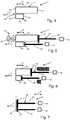
- FIG 1 to 7 A preferred embodiment of an extrusion system 1 according to the invention is shown in FIG 1 to 7 shown, wherein in 1 and 2 a pressing device 10 of the pressing system 1 and in Fig. 2 a cartridge device 40 of the extrusion system 1 is shown.
- the pressing-out device 10 is designed for pressing out multicomponent masses, the masses being able to be provided, for example, for filling, gluing or sealing or similar applications in the construction sector.
- the squeezing device 10 is for interaction with an in Fig. 3 shown cartridge device 40, which has two containers designed as cartridges 41 and 42.
- the cartridge device 40 can be arranged in a receiving space 11 of a housing 12 of the extrusion device 10 and can contain, for example, a two-component mortar composition.
- a curable resin component can be arranged in a chamber or cartridge 41 of the cartridge device 40 and a hardener component can be arranged in the further chamber or cartridge 42 of the cartridge device 40, which is arranged separately from the latter to inhibit the reaction.
- the mass formed after mixing the hardenable resin component and the hardener component is used, for example, as injection mortar for the chemical anchoring of, for example, metal elements in mineral substrates, such as, in particular, structures made of brickwork, concrete or natural stone.
- injection mortar for the chemical anchoring of, for example, metal elements in mineral substrates, such as, in particular, structures made of brickwork, concrete or natural stone.
- the boreholes required for fastening the anchoring means are made in the mineral substrate, after which the hardenable resin component is mixed with the hardening component of the two-component mortar composition and introduced into the borehole, whereupon the anchoring agent to be fastened is inserted and adjusted and the mortar composition then hardens.
- the housing 12 of the pressing device 10 extends essentially along an axial direction A and has a functional section 14 and a handling section 16.
- the functional section 14 essentially has the receiving space 11 and a machining head 19 on a distal end 18 of the functional section 14 on the machining side, into which a squeeze opening of the cartridges 41, 42, not shown, extends. Masses dispensed from the cartridges 41, 42 are mixed in particular in a mixing area 49 of the cartridge device 40 and are dispensed at the processing-side distal end 18 of the functional section 14 to a location to be processed.
- the handling section 16 of the housing 12 has, in addition to a handle 21, an actuating switch 22 which is arranged in the region of the handle 21 and which can be embodied, for example, as a so-called MOSFET switch.
- a pressing-out device 24 is provided for pressing out the cartridges 41, 42, which in the present case has two pressing-out pistons 25, 26, which in the present case are each firmly connected to a push rod 29A or 29B.
- Each ejection piston 25, 26 has a punch 27 or 28 at its end facing the respective cartridge 41 or 42.
- the electric motor 30 for displacing the squeezing piston 25 by means of the push rod 29A in the axial direction A and the electric motor 32 for displacing the squeezing piston 26 by means of the push rod 29B in the axial direction A.
- the squeeze pistons 25, 26 can be individually controlled in the direction of the distal via the push rods 29A and 29B which can be driven in a feed direction V by the electric motors 30, 32 End 18 movable.
- the electric motors 30 and 32 are supplied with energy by an energy supply designed as an accumulator 31.
- the squeezing device 10 can also be network-operated, it being possible to provide a plug which can be coupled to a power network.
- the squeezing device 10 furthermore has a control device 33, which is designed to actuate the electric motors 30 and 32 according to a user request by means of the actuation switch 22.
- the electric motors 30, 32 can be put into different operating modes by the control device 33, a deactivation mode being provided in which no current is fed from the accumulator 31 to the electric motors 30, 32 and actuation of the actuation switch 22 does not result in a displacement of the push rods 29A and 29B leads.
- the electric motors 30, 32 can also be put into an operating mode in which an actuation of the actuation switch 22 by the user leads to a displacement of the squeeze-out pistons 25 and 26 in the feed direction V at a respectively adapted speed.
- the cartridges 41, 42 of the cartridge device 40 each have an essentially cylindrical base body 43 or 44 with a first end wall 45 or 46 and an opposite second end wall 47 or 48.
- a dispensing opening is provided on the first end wall 45 and 46, respectively, which are connected to one another via the mixing region 49.
- an output device in the form of a spout can be connected to the mixing area 49.
- the second end wall 47 or 48 is designed to cooperate with the plunger 27 or 28 of the respective ejection piston 25 or 26, with a volume when the ejection piston 25 or 26 is displaced in the feed direction V in the direction of the first end wall 45 or 46 of the base body 43 or 44 of the respective cartridge 41 or 42 is reduced, so that the respective mass in the cartridges 41 and 42 is carried out through the dispensing opening, is mixed with one another in the mixing region 49 and is pressed out via the dispensing device.
- the squeezing system 1 also has a transmission device 60 which has at least one sensor 61 arranged on the squeezing device 10 and a signal transmitter 62 arranged on the cartridge device 40.
- the transmission device 60 is designed wirelessly and can operate using a variety of transmission principles. In particular, it is an RFID transmission device, but it can alternatively also be, for example, a Bluetooth transmission device, an NFC transmission device, a WiFi transmission device, a QR transmission device, a DMC transmission device, a WLAN transmission device, a ZigBee transmission device, a Wibree transmission device, a WiMAX transmission device, an IrDA transmission device or a transmission device operating according to optical directional radio.
- the signal transmitter 62 is arranged on an end face 50 of the mixing region 49 of the cartridge device 40
- the sensor 61 is arranged on the housing 12 of the dispenser 10 in such a way that the signal transmitter 62 of the cartridge device 40 with the cartridge device 40 arranged in the receiving space 11 in a prescribed manner interacts with the sensor 61 and signals can be transmitted from the signal generator 62 to the sensor 61.
- the sensor 61 is arranged, for example, in the region of a wall of the housing 12 which delimits a distal end region of the receiving region 11.
- the sensor 61 is coupled to the control device 33 by means of a further transmission device 65, it being possible for the further transmission device 65 to be implemented wirelessly or by wire.
- the further transmission device 65 can be designed on the basis of the same transmission mechanisms as the transmission device 60.
- the cartridges 41 and 42 of the cartridge device 40 according to Fig. 2 each have an essentially identical length in the axial direction A.
- a desired mixing ratio between the masses in the cartridges 41 and 42 is achieved here by actuating the squeezing pistons 25 and 26 by the respective electric motor 30 or 32 at an essentially identical speed.
- the cartridges 41 and 42 of the cartridge device 40 according to 4 to 7 have a different length in the axial direction A, the first cartridge 41 according to FIG Fig. 4 in the present case in the axial direction A is longer than the second cartridge 42.
- the first cartridge 41 is, for example, three times as long as the second cartridge 42 in the axial direction A.
- the first cartridge 41 is to be actuated in the present case at a feed rate of the first ejection piston 25 that is three times as high as the ejection piston 26 of the second cartridge 42.
- Fig. 5 are the ejection pistons 25, 26 each moved into a starting position, the plunger 27 of the first ejection plunger 25 essentially in contact with the first cartridge 41 of the cartridge device 40 and the plunger 28 of the second ejection piston 26 essentially in contact with the second cartridge 42 of the Cartridge device 40 is.
- Fig. 6 shows schematically a state of the ejection system 1 during an application-side actuation of the actuation switch 22, in which the ejection piston 25 acts on the first cartridge 41 at a feed rate that is three times the feed rate at which the ejection piston 26 acts on the second cartridge 42.
- the ratio of the feed speeds of the squeezing pistons 25 and 26 corresponds to a ratio of the lengths of the cartridges 41 and 42.
- Fig. 7 shows the squeezing pistons 25 and 26 in each case in a completely extended position, in which both the first cartridge 41 and the second cartridge 42 are essentially completely squeezed out.
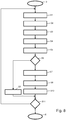
- FIG. 8 An embodiment of a method according to the invention for operating the squeezing system 1 is shown, the actuation of the squeezing pistons 25 and 26 being particularly adjustable by means of the method using the cartridge device 40 currently used. In this case, an incorrect setting with possible damage to both the dispensing device 10 and the cartridge device 40 can be reliably prevented.
- step S1 the cartridge device 40 is inserted into the receiving space 11.
- step S2 the signal transmitter 62 sends the cartridge device 40 a first signal, which specifies the cartridge device 40 in particular with regard to the length of the individual cartridges 41 and 42.
- the cartridge device 40 also additionally sends out a third signal and a fourth signal, the third signal specifying a starting position of the respective squeezing pistons 25 and 26.
- the fourth signal includes, for example, a date of expiration of the cartridge device 40, a permissible temperature range in the surrounding area for processing, or the like.
- the signals emitted by the cartridge device 40 are received by the sensor 61 of the extrusion device 10 in step S3 with the cartridge device 40 arranged in the receiving space 11 in a prescribed manner.
- step S4 the first signal, the third signal and the fourth signal are generated or generated from the first signal, the third signal and the fourth signal second signals sent from the sensor 61 to the control device 33.
- step S5 a ratio of feed speeds for the squeezing pistons 25 and 26 transmitted in the first signal is stored in a memory device 34 of the control device 33.
- the starting positions for the squeezing pistons 25 and 26 transmitted with the third signal are stored in the storage device 34.
- the second signal correlating with the fourth signal is compared, for example, with a current ambient temperature determined by a temperature sensor and, in the event that the current ambient temperature is within a permissible temperature range for the cartridge device 40, continue with step S7.
- it can be compared in query step S5 whether the current date lies before the permissible expiration date of the cartridge device 40. If the result is positive, continue with query step S7.
- step S6 If the query result in query step S6 is negative, the electric motors 30 and 32 are put into the deactivation mode by the control device 33 in step S8, so that actuation of the actuation switch 22 does not lead to a displacement of the push rods 29A and 29B and thus of the squeeze-out pistons 25 and 26.
- step S8 the control device 33 controls the electric motors 30, 32 in such a way that they are moved into the starting positions stored in the storage device 34, in which the punches 27 and 28 each essentially on the respective cartridge 41 and 42 concerns. Then, in step S9, the electric motors 30 and 32 are each transferred from the control device 33 into the operating mode. Subsequent actuation of the actuation switch 22 by the user leads in step S10 to the displacement of the squeeze-out pistons 25, 26 by the electric motors 30, 32.
- step S11 a query is made as to whether relevant framework conditions to be defined have changed to a predetermined extent. If the result of the query is positive, the method continues at step S1. If the query result is negative, the method is ended in step E.
- the cartridge device 40 used in each case is squeezed by the squeezing device 10 to the intended extent at the intended feed speeds of the squeezing pistons 25 and 26 and a desired mixing ratio of the cartridges 41 and 42 located in the cartridges Masses is achieved. Furthermore, damage to both the squeezing device 10 and the cartridge device 40 is prevented, which in conventional squeezing systems is caused, for example, by an incorrect setting of a Ratio of feed speeds of ejection pistons could occur.
- the transmission of corresponding data from the cartridge device 40 to the squeezing device 10 can easily prevent the cartridge device 40 from being used under definable impermissible general conditions which can lead to undesired processing results. It can also be prevented that damage to the cartridge device 40 and / or the squeezing device 10 occurs as a result of a cartridge device 40 incorrectly arranged in the receiving space if the signal transmitter 62 and the sensor 61 are designed and arranged such that a signal transmission between the signal transmitter 62 and the sensor 61 only takes place when the cartridge device 40 is arranged in the receiving space 11 to a prescribed extent.
- the squeezing device 10 has, in particular, an output device 70, which is designed, for example, to output a warning signal in an optical, acoustic and / or haptic manner when the electric motors 30 and 32 are transferred to the operating mode by the control device 33 in step S9.
- the control device 33 can also have a further memory device 72, which is designed to at least temporarily store the first signal, the second signal, the third signal and / or the fourth signal, and which can be read out via an output device. In this way, usage information of the pressing system 1 can be evaluated in a simple manner.
Landscapes
- Engineering & Computer Science (AREA)
- Mechanical Engineering (AREA)
- Computer Networks & Wireless Communication (AREA)
- Signal Processing (AREA)
- Coating Apparatus (AREA)
- Application Of Or Painting With Fluid Materials (AREA)
Priority Applications (7)
| Application Number | Priority Date | Filing Date | Title |
|---|---|---|---|
| EP18212582.3A EP3666401A1 (fr) | 2018-12-14 | 2018-12-14 | Procédé de fonctionnement d'un système de pression et système de pression |
| JP2021530058A JP2022510197A (ja) | 2018-12-14 | 2019-11-25 | 吐出システムを作動させるための方法および吐出システム |
| AU2019395691A AU2019395691B2 (en) | 2018-12-14 | 2019-11-25 | Method for operating a press system, and press system |
| PCT/EP2019/082376 WO2020120113A1 (fr) | 2018-12-14 | 2019-11-25 | Procédé pour faire fonctionner un système de distribution par pression et système de distribution par pression |
| EP19805707.7A EP3894095A1 (fr) | 2018-12-14 | 2019-11-25 | Procédé pour faire fonctionner un système de distribution par pression et système de distribution par pression |
| CA3118181A CA3118181A1 (fr) | 2018-12-14 | 2019-11-25 | Procede pour faire fonctionner un systeme de distribution par pression et systeme de distribution par pression |
| US17/298,770 US11458503B2 (en) | 2018-12-14 | 2019-11-25 | Method for operating an extrusion system and extrusion system |
Applications Claiming Priority (1)
| Application Number | Priority Date | Filing Date | Title |
|---|---|---|---|
| EP18212582.3A EP3666401A1 (fr) | 2018-12-14 | 2018-12-14 | Procédé de fonctionnement d'un système de pression et système de pression |
Publications (1)
| Publication Number | Publication Date |
|---|---|
| EP3666401A1 true EP3666401A1 (fr) | 2020-06-17 |
Family
ID=64899199
Family Applications (2)
| Application Number | Title | Priority Date | Filing Date |
|---|---|---|---|
| EP18212582.3A Withdrawn EP3666401A1 (fr) | 2018-12-14 | 2018-12-14 | Procédé de fonctionnement d'un système de pression et système de pression |
| EP19805707.7A Withdrawn EP3894095A1 (fr) | 2018-12-14 | 2019-11-25 | Procédé pour faire fonctionner un système de distribution par pression et système de distribution par pression |
Family Applications After (1)
| Application Number | Title | Priority Date | Filing Date |
|---|---|---|---|
| EP19805707.7A Withdrawn EP3894095A1 (fr) | 2018-12-14 | 2019-11-25 | Procédé pour faire fonctionner un système de distribution par pression et système de distribution par pression |
Country Status (6)
| Country | Link |
|---|---|
| US (1) | US11458503B2 (fr) |
| EP (2) | EP3666401A1 (fr) |
| JP (1) | JP2022510197A (fr) |
| AU (1) | AU2019395691B2 (fr) |
| CA (1) | CA3118181A1 (fr) |
| WO (1) | WO2020120113A1 (fr) |
Families Citing this family (4)
| Publication number | Priority date | Publication date | Assignee | Title |
|---|---|---|---|---|
| EP3666401A1 (fr) * | 2018-12-14 | 2020-06-17 | Hilti Aktiengesellschaft | Procédé de fonctionnement d'un système de pression et système de pression |
| EP4011506A1 (fr) | 2020-12-10 | 2022-06-15 | Hilti Aktiengesellschaft | Distributeur et procédé de commande du distributeur |
| EP4011507A1 (fr) | 2020-12-10 | 2022-06-15 | Hilti Aktiengesellschaft | Distributeur et procédé de commande du distributeur |
| EP4011505A1 (fr) | 2020-12-10 | 2022-06-15 | Hilti Aktiengesellschaft | Distributeur et procédé de commande du distributeur |
Citations (6)
| Publication number | Priority date | Publication date | Assignee | Title |
|---|---|---|---|---|
| US20030022128A1 (en) * | 2001-07-26 | 2003-01-30 | Ernst Muhlbauer Gmbh & Co.Kg | Method and device for generating a multi-component compound |
| DE102011075873A1 (de) * | 2011-05-16 | 2012-11-22 | Hilti Aktiengesellschaft | Auspressgerät und Gebinde für ein Auspressgerät |
| US20130075427A1 (en) * | 2011-09-28 | 2013-03-28 | Ksaria Corporation | Epoxy dispensing system and dispensing tip used therewith |
| US20140209630A1 (en) * | 2013-01-31 | 2014-07-31 | Owens Corning Intellectual Capital, Llc | Method and apparatus for mixing and applying material |
| DE102016213882A1 (de) * | 2016-07-28 | 2018-02-01 | Robert Bosch Gmbh | Mobile Dosiervorrichtung |
| US20180185117A1 (en) * | 2015-07-02 | 2018-07-05 | Ivoclar Vivadent Ag | Injection Device |
Family Cites Families (8)
| Publication number | Priority date | Publication date | Assignee | Title |
|---|---|---|---|---|
| EP1834603A1 (fr) * | 2006-03-10 | 2007-09-19 | 3M Innovative Properties Company | Appareil et méthode de distribution d'un matériau dentaire |
| EP2470932A2 (fr) * | 2009-08-28 | 2012-07-04 | 3M Innovative Properties Company | Coupe-fibre optique sans lame |
| EP2606986A1 (fr) * | 2011-12-21 | 2013-06-26 | Sika Technology AG | Système d'entraînement d'un dispositif de dosage et de mélange pour matières à plusieurs composants |
| EP2606985A1 (fr) * | 2011-12-21 | 2013-06-26 | Sika Technology AG | Système d'entraînement d'un dispositif de dosage et de mélange |
| EP2606984A1 (fr) * | 2011-12-21 | 2013-06-26 | Sika Technology AG | Dispositif d'entraînement d'un dispositif de dosage et de mélange |
| EP3666401A1 (fr) * | 2018-12-14 | 2020-06-17 | Hilti Aktiengesellschaft | Procédé de fonctionnement d'un système de pression et système de pression |
| EP3666400A1 (fr) * | 2018-12-14 | 2020-06-17 | Hilti Aktiengesellschaft | Procédé de fonctionnement d'un système de pression et système de pression |
| EP3756756A1 (fr) * | 2019-06-28 | 2020-12-30 | Sulzer Mixpac AG | Mélangeur, procédé de fabrication d'un mélangeur, ensemble de distribution et procédé de distribution de matériaux |
-
2018
- 2018-12-14 EP EP18212582.3A patent/EP3666401A1/fr not_active Withdrawn
-
2019
- 2019-11-25 JP JP2021530058A patent/JP2022510197A/ja active Pending
- 2019-11-25 WO PCT/EP2019/082376 patent/WO2020120113A1/fr not_active Ceased
- 2019-11-25 US US17/298,770 patent/US11458503B2/en active Active
- 2019-11-25 AU AU2019395691A patent/AU2019395691B2/en active Active
- 2019-11-25 EP EP19805707.7A patent/EP3894095A1/fr not_active Withdrawn
- 2019-11-25 CA CA3118181A patent/CA3118181A1/fr active Pending
Patent Citations (6)
| Publication number | Priority date | Publication date | Assignee | Title |
|---|---|---|---|---|
| US20030022128A1 (en) * | 2001-07-26 | 2003-01-30 | Ernst Muhlbauer Gmbh & Co.Kg | Method and device for generating a multi-component compound |
| DE102011075873A1 (de) * | 2011-05-16 | 2012-11-22 | Hilti Aktiengesellschaft | Auspressgerät und Gebinde für ein Auspressgerät |
| US20130075427A1 (en) * | 2011-09-28 | 2013-03-28 | Ksaria Corporation | Epoxy dispensing system and dispensing tip used therewith |
| US20140209630A1 (en) * | 2013-01-31 | 2014-07-31 | Owens Corning Intellectual Capital, Llc | Method and apparatus for mixing and applying material |
| US20180185117A1 (en) * | 2015-07-02 | 2018-07-05 | Ivoclar Vivadent Ag | Injection Device |
| DE102016213882A1 (de) * | 2016-07-28 | 2018-02-01 | Robert Bosch Gmbh | Mobile Dosiervorrichtung |
Also Published As
| Publication number | Publication date |
|---|---|
| AU2019395691A1 (en) | 2021-05-27 |
| US20220032337A1 (en) | 2022-02-03 |
| WO2020120113A1 (fr) | 2020-06-18 |
| CA3118181A1 (fr) | 2020-06-18 |
| EP3894095A1 (fr) | 2021-10-20 |
| JP2022510197A (ja) | 2022-01-26 |
| US11458503B2 (en) | 2022-10-04 |
| AU2019395691B2 (en) | 2025-01-23 |
Similar Documents
| Publication | Publication Date | Title |
|---|---|---|
| EP3894096B1 (fr) | Procédé de fonctionnement d'un système de pression et système de pression | |
| EP3666401A1 (fr) | Procédé de fonctionnement d'un système de pression et système de pression | |
| EP2794121B1 (fr) | Dispositif d'entraînement d'un dispositif de dosage et de mélange | |
| DE3128611C2 (de) | Dosiergerät für Mehrkomponenten-Massen | |
| EP2794122B1 (fr) | Système d'entraînement d'un dispositif de dosage et de mélange pour matières à plusieurs composants | |
| EP2314384B1 (fr) | Dispositif de compression | |
| EP3632567B1 (fr) | Dispositif de pipetage pour pipeter de petits volumes liquides | |
| EP2794120B1 (fr) | Système d'entraînement d'un dispositif de dosage et de mélange | |
| EP1279379A1 (fr) | Méthode et dispositif destinés à l'obtention d'une masse à plusieurs composantes, en particulier pour des applications dentaires | |
| WO2020011787A1 (fr) | Dispositif de pipetage pour pipetage par impulsions par déplacement du piston de pipetage régulé sur la base d'une détection de la position de piston | |
| DE10020591B4 (de) | Ausgabevorrichtung für viskoses Dentalmaterial | |
| EP1595602B1 (fr) | Dispositif d'extrusion | |
| DE102011075873A1 (de) | Auspressgerät und Gebinde für ein Auspressgerät | |
| EP3718501B1 (fr) | Dispositif d'extrusion pour matières dentaires | |
| EP4484020A1 (fr) | Procédé de fonctionnement d'un appareil d'extrusion et appareil d'extrusion | |
| DE102021121588A1 (de) | Vorrichtung zum exakten Dosieren eines Fluides, Dosiersystem sowie Verfahren zum exakten Dosieren eines Fluides | |
| DE102004025752A1 (de) | Magazinieraufsatz | |
| EP3891963B1 (fr) | Procédé de fonctionnement d'un système et système correspondant | |
| DE102007000118A1 (de) | Auspressgerät | |
| EP4379250A1 (fr) | Magasin compact à chambres multiples avec dispositif d'extraction et de mélange intégré | |
| EP1287966B1 (fr) | Positionnement d'une cassette de verrouillage | |
| EP3664059A1 (fr) | Procédé de fonctionnement d'un système et système | |
| WO2007009538A1 (fr) | Procede et dispositif permettant de realiser une masse a plusieurs constituants | |
| DE20109098U1 (de) | Pistole zum Ausstoßen von pastösen Massen |
Legal Events
| Date | Code | Title | Description |
|---|---|---|---|
| PUAI | Public reference made under article 153(3) epc to a published international application that has entered the european phase |
Free format text: ORIGINAL CODE: 0009012 |
|
| STAA | Information on the status of an ep patent application or granted ep patent |
Free format text: STATUS: THE APPLICATION HAS BEEN PUBLISHED |
|
| AK | Designated contracting states |
Kind code of ref document: A1 Designated state(s): AL AT BE BG CH CY CZ DE DK EE ES FI FR GB GR HR HU IE IS IT LI LT LU LV MC MK MT NL NO PL PT RO RS SE SI SK SM TR |
|
| AX | Request for extension of the european patent |
Extension state: BA ME |
|
| STAA | Information on the status of an ep patent application or granted ep patent |
Free format text: STATUS: THE APPLICATION IS DEEMED TO BE WITHDRAWN |
|
| 18D | Application deemed to be withdrawn |
Effective date: 20201218 |